Download - Mold Design & Manufacturing Process(Catia)

© 1
997
– 20
04 D
ASS
AU
LT S
YSTE
MES
Page 1IBM PLM / IBM Business Partners / Dassault Systemes Internal Use Only
V5R13 Generative Mold - Design & Manufacturing
Mold Design & Manufacturing Process
CATIA Demonstration Script
Version 5 Release 13February 2004C513_demMold_Script_DesignManufacturing
The demonstration Image Medium size 400X300
© 1
997
– 20
04 D
ASS
AU
LT S
YSTE
MES
IBM PLM / IBM Business Partners / Dassault Systemes Internal Use Only Page 2
V5R13 Generative Mold - Design & Manufacturing Setting up CATIA Environment
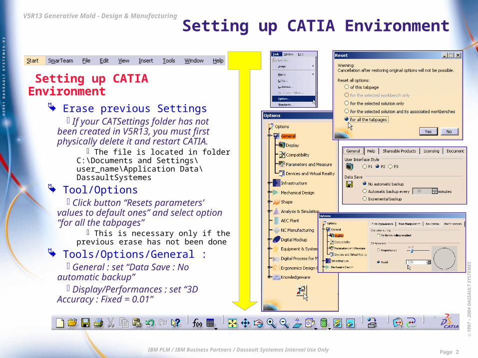
Setting up CATIA Environment Erase previous Settings
If your CATSettings folder has not been created in V5R13, you must first physically delete it and restart CATIA.
The file is located in folder C:\Documents and Settings\user_name\Application Data\DassaultSystemes
Tool/Options Click button “Resets parameters’
values to default ones” and select option “for all the tabpages”
This is necessary only if the previous erase has not been done
Tools/Options/General : General : set “Data Save : No
automatic backup” Display/Performances : set “3D
Accuracy : Fixed = 0.01”

© 1
997
– 20
04 D
ASS
AU
LT S
YSTE
MES
IBM PLM / IBM Business Partners / Dassault Systemes Internal Use Only Page 3
V5R13 Generative Mold - Design & Manufacturing Setting up CATIA Environment
Setting up CATIA Environment
Tools/Options/General : Parameters and
Measures/Knowledge : activate “Parameter Tree View : With value & With formula”
Tools/Options/Infrastructure : Product Structure/Tree Customization
: activate Specification Tree Order : Parameters, Relations, Constraints
Part Infrastructure/Display : activate “Display In Specification Tree : Constraints, Parameters, Relations”

© 1
997
– 20
04 D
ASS
AU
LT S
YSTE
MES
IBM PLM / IBM Business Partners / Dassault Systemes Internal Use Only Page 4
V5R13 Generative Mold - Design & Manufacturing Setting up CATIA Environment
Setting up CATIA Environment
Tools/Options/Mechanical Design : Assembly Design/General : set
“Update : Automatic” Sketcher : deactivate “Grid : Snap to
point” Tools/Options/NC Manufacturing :
Photo/Video : set “Simulation at : Part operation level”

© 1
997
– 20
04 D
ASS
AU
LT S
YSTE
MES
IBM PLM / IBM Business Partners / Dassault Systemes Internal Use Only Page 5
V5R13 Generative Mold - Design & Manufacturing Demo Steps
Step 1 Data Check and Repair
Step 2 Applying local Deformation
Step 3 Core & Cavity Separation
Step 4 Parting Surface Definition
Step 5 Mold Tool Design
Step 6 Mold Tool Drawings
Step 7 2.5- and 3-Axis Manufacturing
11 22
44
55
6677
33
© 1
997
– 20
04 D
ASS
AU
LT S
YSTE
MES
IBM PLM / IBM Business Partners / Dassault Systemes Internal Use Only Page 6
V5R13 Generative Mold - Design & Manufacturing Step 1 : Data Check and Repair
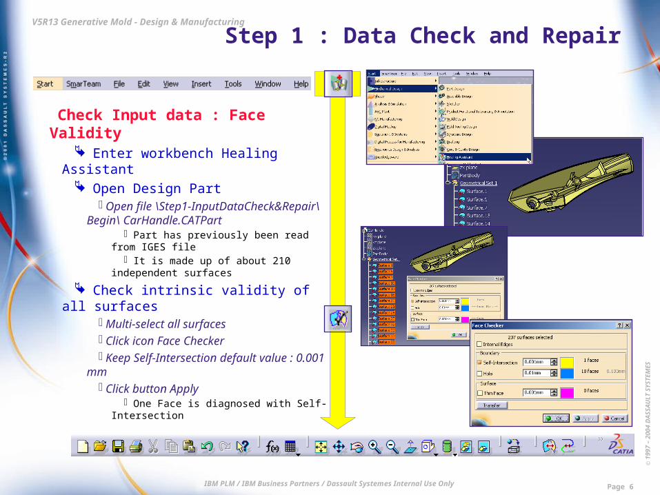
Check Input data : Face Validity Enter workbench Healing Assistant Open Design Part
Open file \Step1-InputDataCheck&Repair\Begin\ CarHandle.CATPart
Part has previously been read from IGES file
It is made up of about 210 independent surfaces
Check intrinsic validity of all surfaces Multi-select all surfaces Click icon Face Checker Keep Self-Intersection default value :
0.001 mm Click button Apply
One Face is diagnosed with Self-Intersection
© 1
997
– 20
04 D
ASS
AU
LT S
YSTE
MES
IBM PLM / IBM Business Partners / Dassault Systemes Internal Use Only Page 7
V5R13 Generative Mold - Design & Manufacturing Step 1 : Data Check and Repair
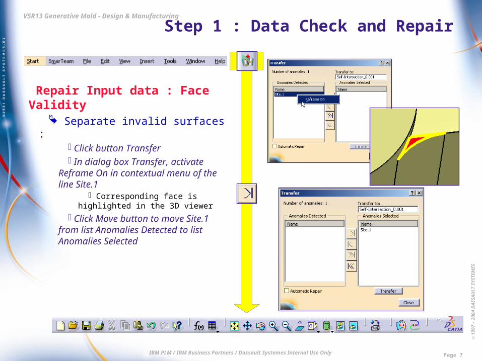
Repair Input data : Face Validity Separate invalid surfaces :
Click button Transfer In dialog box Transfer, activate
Reframe On in contextual menu of the line Site.1
Corresponding face is highlighted in the 3D viewer
Click Move button to move Site.1 from list Anomalies Detected to list Anomalies Selected

© 1
997
– 20
04 D
ASS
AU
LT S
YSTE
MES
IBM PLM / IBM Business Partners / Dassault Systemes Internal Use Only Page 8
V5R13 Generative Mold - Design & Manufacturing Step 1 : Data Check and Repair
Repair Input data : Face Validity Repair invalid surfaces :
Activate option Automatic Repair Click button Close
Surface.92 has been identified as invalid and a new repaired Surface has automatically been created and put in a dedicated separate Geometrical Set
The initial invalid surface is automatically put in NoShow in a dedicated separate Geometrical Set
In dialog box Face Checker, click OK to validate the operation
Hide all elements except the faulty surface and zoom :
The extremities are very sharp : the boundary of the face is probably not clean enough and some of its edges are crisscrossing.
Delete Geometrical Set containing original invalid surface Surface.92
Put back the remaining elements in Show
© 1
997
– 20
04 D
ASS
AU
LT S
YSTE
MES
IBM PLM / IBM Business Partners / Dassault Systemes Internal Use Only Page 9
V5R13 Generative Mold - Design & Manufacturing Step 1 : Data Check and Repair
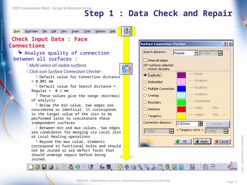
Check Input Data : Face Connections Analyze quality of connection between
all surfaces : Multi-select all visible surfaces Click icon Surface Connection Checker :
Default value for Connection distance = 0.001 mm
Default value for Search distance = Regular = 0.1 mm
These values give the range (min/max) of analysis
Below the min value, two edges are considered as identical. It corresponds to the target value of the Join to be performed later to concatenate these independent surfaces.
Between min and max values, two edges are candidates for merging via Local Join or Local Healing operations
Beyond the max value, elements correspond to functional holes and should not be Joined or are defect faces that should undergo repair before being Joined.
© 1
997
– 20
04 D
ASS
AU
LT S
YSTE
MES
IBM PLM / IBM Business Partners / Dassault Systemes Internal Use Only Page 10
V5R13 Generative Mold - Design & Manufacturing Step 1 : Data Check and Repair
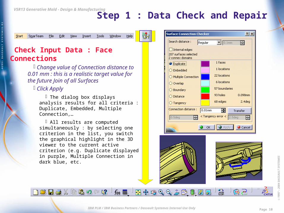
Check Input Data : Face Connections Change value of Connection distance to
0.01 mm : this is a realistic target value for the future Join of all Surfaces
Click Apply The dialog box displays analysis results for
all criteria : Duplicate, Embedded, Multiple Connection,…
All results are computed simultaneously : by selecting one criterion in the list, you switch the graphical highlight in the 3D viewer to the current active criterion (e.g. Duplicate displayed in purple, Multiple Connection in dark blue, etc.

© 1
997
– 20
04 D
ASS
AU
LT S
YSTE
MES
IBM PLM / IBM Business Partners / Dassault Systemes Internal Use Only Page 11
V5R13 Generative Mold - Design & Manufacturing Step 1 : Data Check and Repair
Check Input Data: Duplicate Faces Focus first on duplicate surfaces :
Make sure that the current selected option in the dialog box is Duplicate : 1 duplicate face has been detected
Separate duplicate surfaces : Click button Transfer In dialog box Transfer, click Move
button to move Site.1 from list Anomalies Detected to list Anomalies Selected
Click button Close A new Geometrical Set has
automatically been created to group together the two surfaces detected as identical
In dialog box Surface Connection Checker, click button OK to validate the operation
Delete redundant surfaces : Delete Geometrical Set called Surplus
to eliminate one of the identical surfaces

© 1
997
– 20
04 D
ASS
AU
LT S
YSTE
MES
IBM PLM / IBM Business Partners / Dassault Systemes Internal Use Only Page 12
V5R13 Generative Mold - Design & Manufacturing Step 1 : Data Check and Repair
Check Input Data : Embedded Faces Focus now on embedded surfaces :
Multi-select all visible surfaces Click icon Surface Connection Checker Keep values : Search distance = Regular
= 0.1 mm and Connection distance = 0.01 mm
Click Apply to perform analysis for all criteria
Select criterion Embedded One location has been detected
Separate embedded surfaces : Click button Transfer In dialog box Transfer, click Move button
to move Site.1 from list Anomalies Detected to list Anomalies Selected
Click button Close A new Geometrical Set has been created
In dialog box Surface Connection Checker, click button OK to validate the operation

© 1
997
– 20
04 D
ASS
AU
LT S
YSTE
MES
IBM PLM / IBM Business Partners / Dassault Systemes Internal Use Only Page 13
V5R13 Generative Mold - Design & Manufacturing Step 1 : Data Check and Repair
Repair Input Data : Embedded Faces Delete unnecessary surfaces :
Put the new Geometrical Set in Show mode
Hide Surface.130 : you can see that Surface.129 is embedded in Surface.130
Delete Surface.129

© 1
997
– 20
04 D
ASS
AU
LT S
YSTE
MES
IBM PLM / IBM Business Partners / Dassault Systemes Internal Use Only Page 14
V5R13 Generative Mold - Design & Manufacturing Step 1 : Data Check and Repair
Check Input Data : Overlaps Focus now on overlapping surfaces :
Multi-select all visible surfaces Click icon Surface Connection
Checker Keep previous values : Search
distance = Regular = 0.1 mm and Connection distance = 0.01 mm
Click Apply to perform the analysis for all criteria
Select criterion Overlap 4 locations have been detected Note that solving the duplicate and
embedded cases first has helped reduce the number of overlaps, which was equal to 6 after the first Surface Connection Checker analysis.

© 1
997
– 20
04 D
ASS
AU
LT S
YSTE
MES
IBM PLM / IBM Business Partners / Dassault Systemes Internal Use Only Page 15
V5R13 Generative Mold - Design & Manufacturing Step 1 : Data Check and Repair
Repair Input Data : Overlaps Separate overlapping surfaces :
Click button Transfer In dialog box Transfer, click Move All
button to move Site.1 from list Anomalies Detected to list Anomalies Selected
Click button Close A new Geometrical Set has automatically
been created to group together the surfaces causing the problem
Click button Transfer
© 1
997
– 20
04 D
ASS
AU
LT S
YSTE
MES
IBM PLM / IBM Business Partners / Dassault Systemes Internal Use Only Page 16
V5R13 Generative Mold - Design & Manufacturing Step 1 : Data Check and Repair
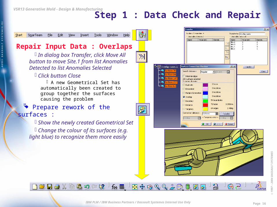
Repair Input Data : Overlaps In dialog box Transfer, click Move All
button to move Site.1 from list Anomalies Detected to list Anomalies Selected
Click button Close A new Geometrical Set has automatically
been created to group together the surfaces causing the problem
Prepare rework of the surfaces : Show the newly created Geometrical Set Change the colour of its surfaces (e.g.
light blue) to recognize them more easily

© 1
997
– 20
04 D
ASS
AU
LT S
YSTE
MES
IBM PLM / IBM Business Partners / Dassault Systemes Internal Use Only Page 17
V5R13 Generative Mold - Design & Manufacturing Step 1 : Data Check and Repair
Repair Input Data : Overlaps First rework action : delete
unnecessary surface : Delete Surface.147 which is
superimposed on Surface.257 Second rework action : replace
surface causing overlap : Focus on connection between
Surface.78 and Surface.84 Zoom in to check the overlap visually Delete Surface.84 Create a new Geometrical Set and make
it current
© 1
997
– 20
04 D
ASS
AU
LT S
YSTE
MES
IBM PLM / IBM Business Partners / Dassault Systemes Internal Use Only Page 18
V5R13 Generative Mold - Design & Manufacturing Step 1 : Data Check and Repair
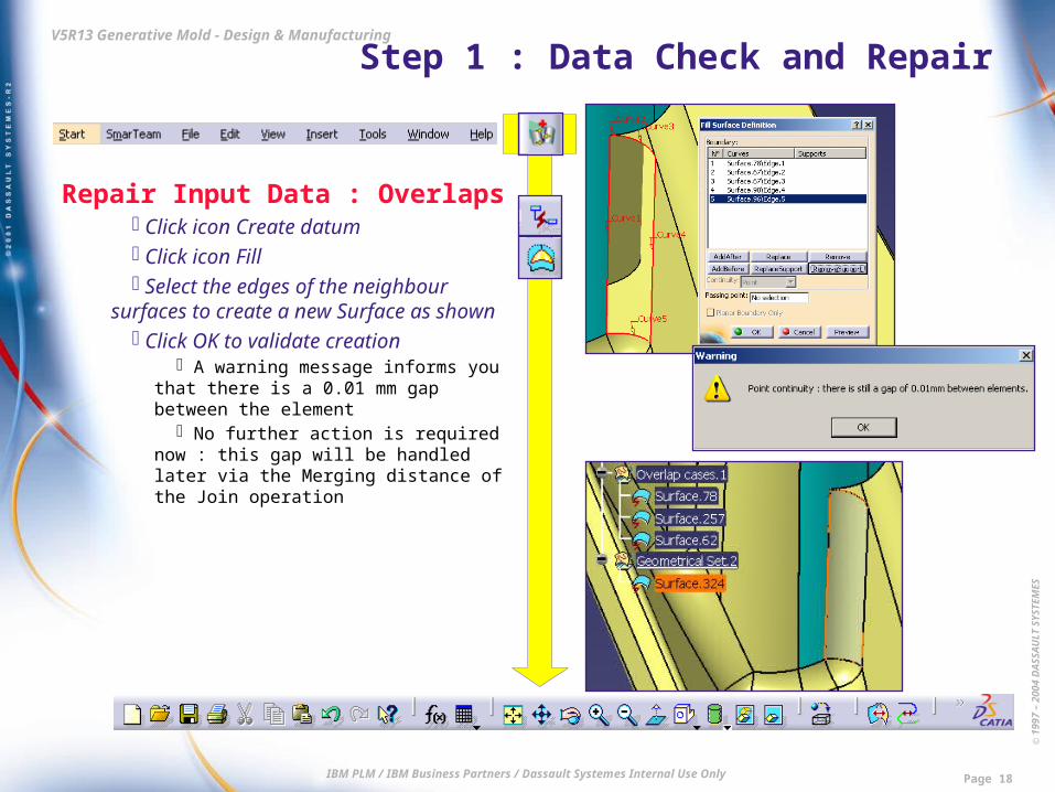
Repair Input Data : Overlaps Click icon Create datum Click icon Fill Select the edges of the neighbour
surfaces to create a new Surface as shown Click OK to validate creation
A warning message informs you that there is a 0.01 mm gap between the element
No further action is required now : this gap will be handled later via the Merging distance of the Join operation
© 1
997
– 20
04 D
ASS
AU
LT S
YSTE
MES
IBM PLM / IBM Business Partners / Dassault Systemes Internal Use Only Page 19
V5R13 Generative Mold - Design & Manufacturing Step 1 : Data Check and Repair
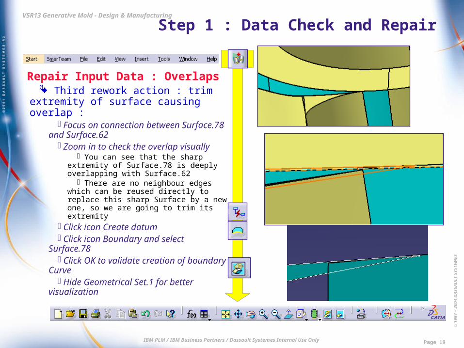
Repair Input Data : Overlaps Third rework action : trim extremity of
surface causing overlap : Focus on connection between
Surface.78 and Surface.62 Zoom in to check the overlap visually
You can see that the sharp extremity of Surface.78 is deeply overlapping with Surface.62
There are no neighbour edges which can be reused directly to replace this sharp Surface by a new one, so we are going to trim its extremity
Click icon Create datum Click icon Boundary and select
Surface.78 Click OK to validate creation of boundary
Curve Hide Geometrical Set.1 for better
visualization

© 1
997
– 20
04 D
ASS
AU
LT S
YSTE
MES
IBM PLM / IBM Business Partners / Dassault Systemes Internal Use Only Page 20
V5R13 Generative Mold - Design & Manufacturing Step 1 : Data Check and Repair
Repair Input Data : Overlaps Click icon Create datum Click icon Projection Select Projected = boundary Curve Select Support = Surface.62 Click OK to validate operation Hide original boundary Curve Click icon Create datum Click icon Line and select User type =
Point-Point Pick successively the two vertices of
the projection Curve Select Support = Surface.62 Click OK to validate creation Click icon Create datum Click icon Projection Select Projected = line Curve Select Support = Surface.78 Click OK to validate operation

© 1
997
– 20
04 D
ASS
AU
LT S
YSTE
MES
IBM PLM / IBM Business Partners / Dassault Systemes Internal Use Only Page 21
V5R13 Generative Mold - Design & Manufacturing Step 1 : Data Check and Repair
Repair Input Data : Overlaps Click icon Create datum Click icon Split Select Element to cut = Surface.78 Select Cutting element = projected
Curve Make sure the appropriate side of
Surface.78 is pre-visualized Click OK to validate operation Delete the wireframe construction
elements previously created Delete Surface.78

© 1
997
– 20
04 D
ASS
AU
LT S
YSTE
MES
IBM PLM / IBM Business Partners / Dassault Systemes Internal Use Only Page 22
V5R13 Generative Mold - Design & Manufacturing Step 1 : Data Check and Repair
Repair Input Data Create Join with all Surfaces
Show Geometrical Set.1 Create a new Geometric Set Multi-select all visible surfaces Click icon Join Deselect option Check Connexity Set merging distance = 0.01 mm Click OK to validate
Compute remaining free edges Select Join Click icon Boundary Click OK Click No in dialog box Multi-result
management in order to keep all sub-elements
The Boundary is created
© 1
997
– 20
04 D
ASS
AU
LT S
YSTE
MES
IBM PLM / IBM Business Partners / Dassault Systemes Internal Use Only Page 23
V5R13 Generative Mold - Design & Manufacturing Step 1 : Data Check and Repair
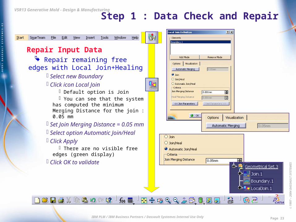
Repair Input Data Repair remaining free edges with
Local Join+Healing Select new Boundary Click icon Local Join
Default option is Join You can see that the system has
computed the minimum Merging Distance for the join : 0.05 mm
Set Join Merging Distance = 0.05 mm
Select option Automatic Join/Heal Click Apply
There are no visible free edges (green display)
Click OK to validate

© 1
997
– 20
04 D
ASS
AU
LT S
YSTE
MES
IBM PLM / IBM Business Partners / Dassault Systemes Internal Use Only Page 24
V5R13 Generative Mold - Design & Manufacturing Step 1 : Data Check and Repair
Repair Input Data Check Join closure
Select Local Join Click icon Boundary
A message informs that the Join is closed
Click Cancel to cancel Boundary creation
Close without Save
End of Step 1. Result data is : \Step1-InputDataCheck&Repair\End\
CarHandle.CATPart

© 1
997
– 20
04 D
ASS
AU
LT S
YSTE
MES
IBM PLM / IBM Business Partners / Dassault Systemes Internal Use Only Page 25
V5R13 Generative Mold - Design & Manufacturing Step 2 : Applying local Deformation
Local Part Deformation Dedicated analysis or previous
experience show that the inner hole is subject to deformation when hot plastic injection is done.
To offset this effect, the opposite deformation can be applied to the original shape to ensure that the final result is really a round hole.
This deformation will be applied thanks to function Shape Morphing (workbench Generative Shape Optimizer is necessary).
Applying the deformation will be applied in a quick and convenient way thanks to Powercopy capability.
© 1
997
– 20
04 D
ASS
AU
LT S
YSTE
MES
IBM PLM / IBM Business Partners / Dassault Systemes Internal Use Only Page 26
V5R13 Generative Mold - Design & Manufacturing Step 2 : Applying local Deformation
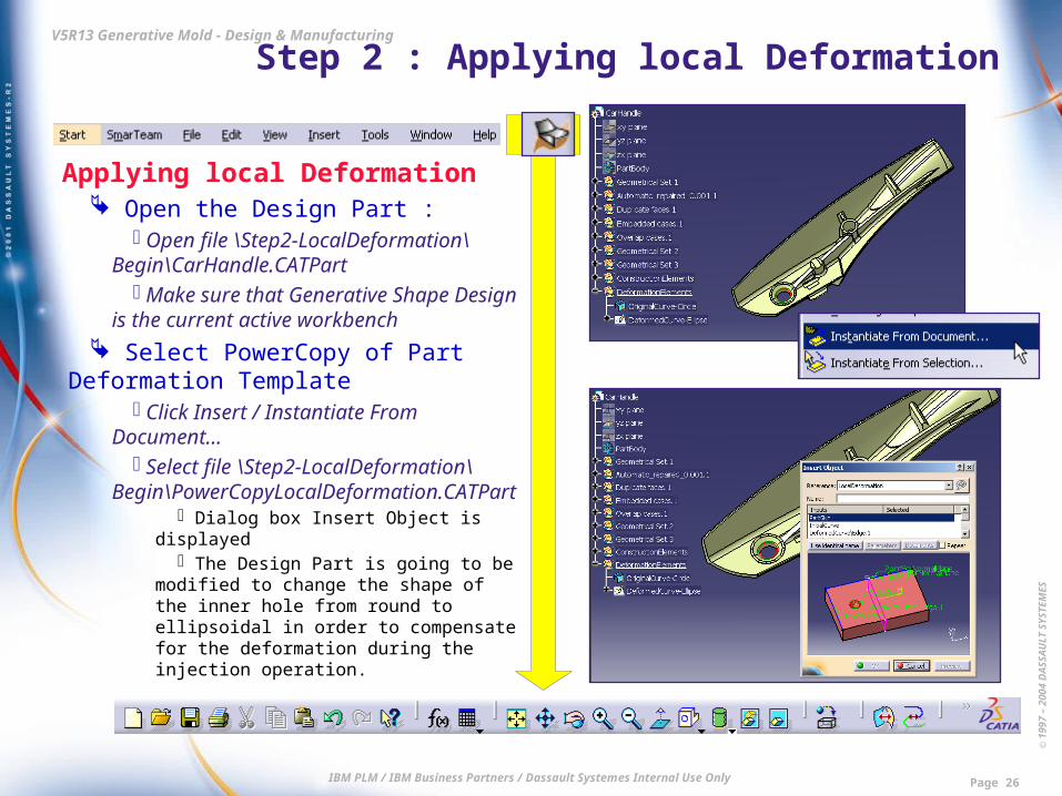
Applying local Deformation Open the Design Part :
Open file \Step2-LocalDeformation\Begin\CarHandle.CATPart
Make sure that Generative Shape Design is the current active workbench
Select PowerCopy of Part Deformation Template
Click Insert / Instantiate From Document…
Select file \Step2-LocalDeformation\Begin\PowerCopyLocalDeformation.CATPart
Dialog box Insert Object is displayed The Design Part is going to be modified to
change the shape of the inner hole from round to ellipsoidal in order to compensate for the deformation during the injection operation.

© 1
997
– 20
04 D
ASS
AU
LT S
YSTE
MES
IBM PLM / IBM Business Partners / Dassault Systemes Internal Use Only Page 27
V5R13 Generative Mold - Design & Manufacturing Step 2 : Applying local Deformation
Applying local Deformation Select the Part to be deformed
Pick the Local Join feature This corresponds to expected
PowerCopy input named PartSkin
Select the original round hole curve Pick prepared red curve called
OriginalCurve-Circle This corresponds to expected
PowerCopy input named InitialCurve
Select the target ellipse curve Pick prepared green curve called
TargetCurve-Ellipse This corresponds to expected
PowerCopy input named DeformedCurve
© 1
997
– 20
04 D
ASS
AU
LT S
YSTE
MES
IBM PLM / IBM Business Partners / Dassault Systemes Internal Use Only Page 28
V5R13 Generative Mold - Design & Manufacturing Step 2 : Applying local Deformation
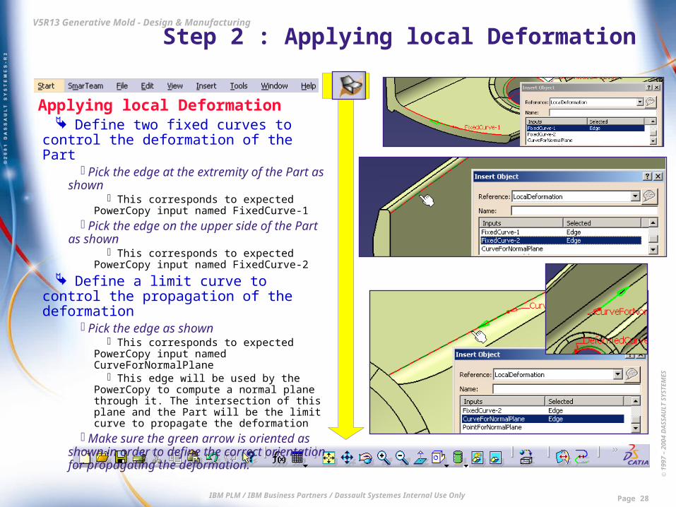
Applying local Deformation Define two fixed curves to control the
deformation of the Part Pick the edge at the extremity of the Part
as shown This corresponds to expected PowerCopy
input named FixedCurve-1 Pick the edge on the upper side of the
Part as shown This corresponds to expected PowerCopy
input named FixedCurve-2 Define a limit curve to control the
propagation of the deformation Pick the edge as shown
This corresponds to expected PowerCopy input named CurveForNormalPlane
This edge will be used by the PowerCopy to compute a normal plane through it. The intersection of this plane and the Part will be the limit curve to propagate the deformation
Make sure the green arrow is oriented as shown in order to define the correct orientation for propagating the deformation.

© 1
997
– 20
04 D
ASS
AU
LT S
YSTE
MES
IBM PLM / IBM Business Partners / Dassault Systemes Internal Use Only Page 29
V5R13 Generative Mold - Design & Manufacturing Step 2 : Applying local Deformation
Applying local Deformation Pick the vertex as shown
This corresponds to expected PowerCopy input named PointForNormalPlane
This point will be used by the PowerCopy to compute the normal plane, then the limit curve mentioned before.
Create the deformation Click button Preview to check the
computed result Click OK to validate the creation of
the Shape Morphing feature Hide Local Join to better visualize
the final result Close without Save
End of Step 2. Result data is : \Step2-LocalDeformation\End\
CarHandle.CATPart

© 1
997
– 20
04 D
ASS
AU
LT S
YSTE
MES
IBM PLM / IBM Business Partners / Dassault Systemes Internal Use Only Page 30
V5R13 Generative Mold - Design & Manufacturing Step 3 : Core & Cavity Separation
Create Molded Part Import Part to mold
Create new empty Product and make it active (highlighted in orange)
Enter workbench Core & Cavity Design Click icon Import model Select Reference = \Step3-
CoreCavitySeparation\Begin\CarHandle.CATPart
Select Body = DeformationElements Surface Shape Morphing.1 is automatically
selected Select Axis System = Local axis system Select shrinkage : Scaling Ratio = 1.01 Click OK to validate Reframe on the Part
A solid element (ClosedSurface) has been created and the corresponding scaling value has automatically been applied

© 1
997
– 20
04 D
ASS
AU
LT S
YSTE
MES
IBM PLM / IBM Business Partners / Dassault Systemes Internal Use Only Page 31
V5R13 Generative Mold - Design & Manufacturing Step 3 : Core & Cavity Separation
Define Main Pulling Direction Define Mold areas
Click icon Define pulling direction Drag and drop compass origin (red
square point) onto the bottom of the inner hole of the part
Click anywhere on the part A coloured display shows the mold areas
of the part : Core in Red, Cavity in Green, Other (to be reworked) in blue, and No Draft (vertical faces, according to value of Draft angle) in pink
Click button Reverse if necessary This is to ensure that Z+ axis of the
pulling direction is oriented towards the outer side of the Part and that Core side (red) corresponds to the inner side of the Part
Activate option Locked This will prevent any erroneous
displacement during further operations

© 1
997
– 20
04 D
ASS
AU
LT S
YSTE
MES
IBM PLM / IBM Business Partners / Dassault Systemes Internal Use Only Page 32
V5R13 Generative Mold - Design & Manufacturing Step 3 : Core & Cavity Separation
Define Main Pulling Direction Refine mold areas : Facets to ignore
Zoom in onto one of the blue faces located among the Core side
Select option Visualization = Facet display to check the defects
You can see that these faces are not quite moldable because of insufficient quality of design.
However, the defects are not too big, so we will reassign these faces to Core side.
A similar analysis could be done for other blue faces
Select option Visualization = Face display
Activate option Facets to ignore Keep default maximum ratio value (15 %) You can see that many blue faces have
been automatically transferred to Core side or Cavity side

© 1
997
– 20
04 D
ASS
AU
LT S
YSTE
MES
IBM PLM / IBM Business Partners / Dassault Systemes Internal Use Only Page 33
V5R13 Generative Mold - Design & Manufacturing Step 3 : Core & Cavity Separation
Define Main Pulling Direction Refine mold areas : Explode mode
Activate option Visualization = Explode Set the translation value to 50mm
Core side (red faces) and Cavity side (green faces) are moved apart accordingly, thus enabling to see more clearly which remaining blue faces could be redistributed to Core or Cavity areas.
Refine mold areas : Local Transfer to Core
Activate option Local Transfer Keep default destination = Core Select propagation type = No
propagation Click the two blue faces as shown

© 1
997
– 20
04 D
ASS
AU
LT S
YSTE
MES
IBM PLM / IBM Business Partners / Dassault Systemes Internal Use Only Page 34
V5R13 Generative Mold - Design & Manufacturing Step 3 : Core & Cavity Separation
Define Main Pulling Direction Refine mold areas : Local Transfer
to Cavity Select default destination = Cavity Keep propagation type = No
propagation Click the blue faces as shown Click OK to validate the creation of the
Mold areas. Further rework has still to be done Four Geometrical Sets have
automatically been created : Core, Cavity, Other, NoDraft
An Axis System has automatically been created (Main Pulling Direction.1)

© 1
997
– 20
04 D
ASS
AU
LT S
YSTE
MES
IBM PLM / IBM Business Partners / Dassault Systemes Internal Use Only Page 35
V5R13 Generative Mold - Design & Manufacturing Step 3 : Core & Cavity Separation
Define Slider area Define Slider area
Click icon Defines slider lifter direction Drag and drop the compass onto the
inner face of the undercut area Note that the corresponding face has
switched from pink to yellow, which is the typical colour of a Slider/lifter area
Activate option Locked Activate option Local Transfer Keep default destination = Slider/Lifter Select propagation type = Point
continuity Pick successively pink, blue, green and
red faces of the undercut area Click OK to validate
A new Geometrical Set has automatically been created : Slider/Lifter.1
An Axis System has automatically been created (Main Pulling Direction.1)
© 1
997
– 20
04 D
ASS
AU
LT S
YSTE
MES
IBM PLM / IBM Business Partners / Dassault Systemes Internal Use Only Page 36
V5R13 Generative Mold - Design & Manufacturing Step 3 : Core & Cavity Separation
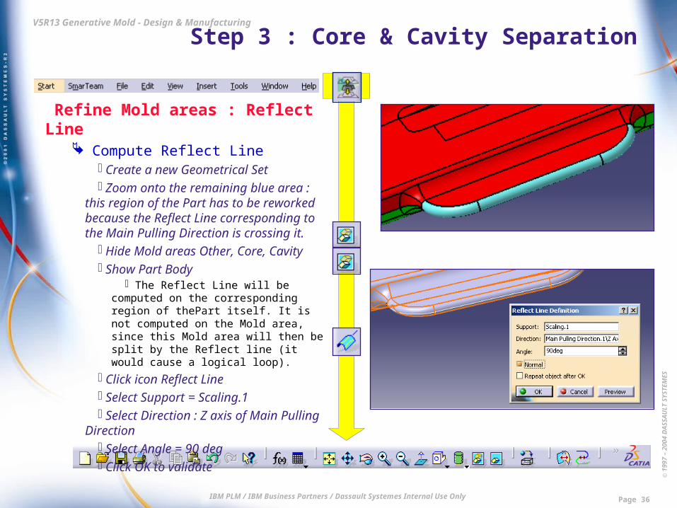
Refine Mold areas : Reflect Line Compute Reflect Line
Create a new Geometrical Set Zoom onto the remaining blue area :
this region of the Part has to be reworked because the Reflect Line corresponding to the Main Pulling Direction is crossing it.
Hide Mold areas Other, Core, Cavity Show Part Body
The Reflect Line will be computed on the corresponding region of thePart itself. It is not computed on the Mold area, since this Mold area will then be split by the Reflect line (it would cause a logical loop).
Click icon Reflect Line Select Support = Scaling.1 Select Direction : Z axis of Main
Pulling Direction Select Angle = 90 deg Click OK to validate

© 1
997
– 20
04 D
ASS
AU
LT S
YSTE
MES
IBM PLM / IBM Business Partners / Dassault Systemes Internal Use Only Page 37
V5R13 Generative Mold - Design & Manufacturing Step 3 : Core & Cavity Separation
Refine Mold areas : Reflect Line Restrict Reflect Line
Click Yes in dialog box Multi-Result Management
The Reflect Line is made up of several discontinuous pieces : we will keep only the relevant piece
Pick one face or edge near the desired piece of the Reflect Line
Click OK to validate
© 1
997
– 20
04 D
ASS
AU
LT S
YSTE
MES
IBM PLM / IBM Business Partners / Dassault Systemes Internal Use Only Page 38
V5R13 Generative Mold - Design & Manufacturing Step 3 : Core & Cavity Separation
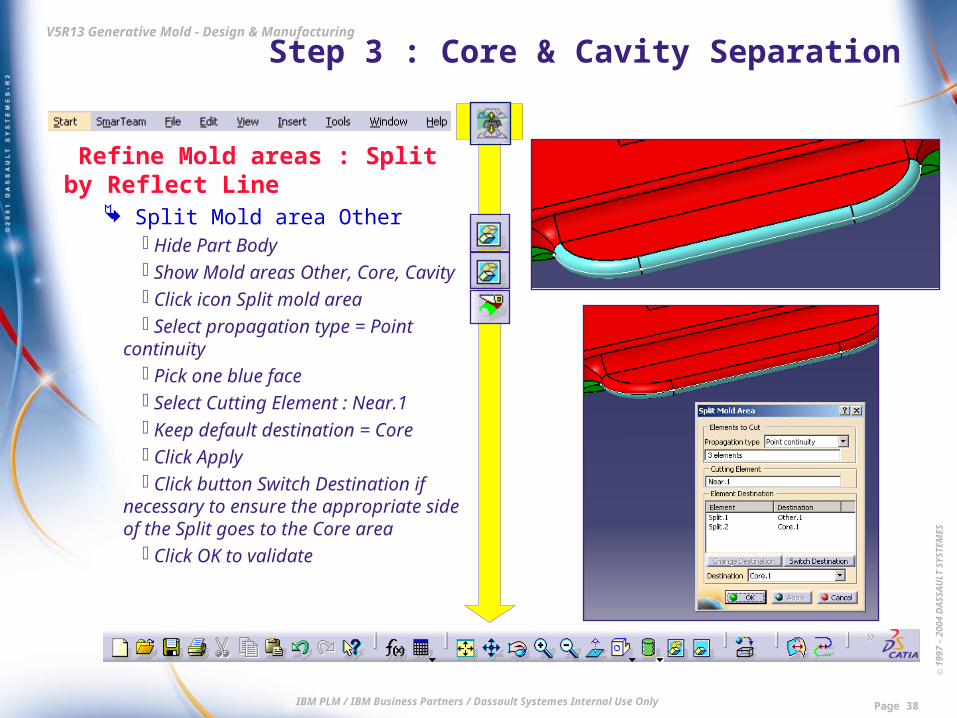
Refine Mold areas : Split by Reflect Line
Split Mold area Other Hide Part Body Show Mold areas Other, Core, Cavity Click icon Split mold area Select propagation type = Point
continuity Pick one blue face Select Cutting Element : Near.1 Keep default destination = Core Click Apply Click button Switch Destination if
necessary to ensure the appropriate side of the Split goes to the Core area
Click OK to validate

© 1
997
– 20
04 D
ASS
AU
LT S
YSTE
MES
IBM PLM / IBM Business Partners / Dassault Systemes Internal Use Only Page 39
V5R13 Generative Mold - Design & Manufacturing Step 3 : Core & Cavity Separation
Refine Mold areas : Transfer Faces Transfer remaining blue faces to
Cavity area Click icon Transfer an element Select Propagation type = Point
continuity Select Destination = Cavity Pick one blue face Click OK to validate
Final check Click icon Explode View Set Explode Value = 50 mm Click Cancel to close Exploded View
Close without Save End of Step 3. Result data is : \Step3-CoreCavitySeparation\End\
Product1.CATProduct
© 1
997
– 20
04 D
ASS
AU
LT S
YSTE
MES
IBM PLM / IBM Business Partners / Dassault Systemes Internal Use Only Page 40
V5R13 Generative Mold - Design & Manufacturing Step 4 : Parting Surface Creation
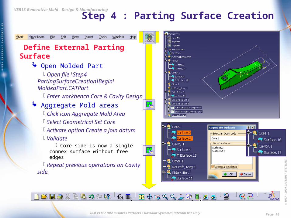
Define External Parting Surface Open Molded Part
Open file \Step4-PartingSurfaceCreation\Begin\MoldedPart.CATPart
Enter workbench Core & Cavity Design
Aggregate Mold areas Click icon Aggregate Mold Area Select Geometrical Set Core Activate option Create a join datum Validate
Core side is now a single connex surface without free edges
Repeat previous operations on Cavity side.
© 1
997
– 20
04 D
ASS
AU
LT S
YSTE
MES
IBM PLM / IBM Business Partners / Dassault Systemes Internal Use Only Page 41
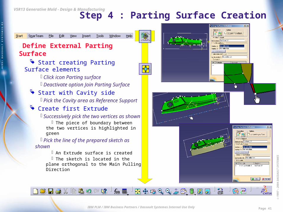
V5R13 Generative Mold - Design & Manufacturing Step 4 : Parting Surface Creation
Define External Parting Surface Start creating Parting Surface
elements Click icon Parting surface Deactivate option Join Parting Surface
Start with Cavity side Pick the Cavity area as Reference
Support Create first Extrude
Successively pick the two vertices as shown
The piece of boundary between the two vertices is highlighted in green
Pick the line of the prepared sketch as shown
An Extrude surface is created The sketch is located in the plane
orthogonal to the Main Pulling Direction

© 1
997
– 20
04 D
ASS
AU
LT S
YSTE
MES
IBM PLM / IBM Business Partners / Dassault Systemes Internal Use Only Page 42
V5R13 Generative Mold - Design & Manufacturing Step 4 : Parting Surface Creation
Define External Parting Surface Create second Extrude
Successively pick the two vertices as shown
Pick the line of the prepared sketch as shown
An Extrude surface is created
Create third Extrude Successively pick the two vertices
as shown Pick the line of the prepared sketch
as shown An Extrude surface is created

© 1
997
– 20
04 D
ASS
AU
LT S
YSTE
MES
IBM PLM / IBM Business Partners / Dassault Systemes Internal Use Only Page 43
V5R13 Generative Mold - Design & Manufacturing Step 4 : Parting Surface Creation
Define External Parting Surface Create fourth Extrude
Successively pick the two vertices as shown
Pick the side of the prepared sketch as shown
An Extrude surface is created The sketch is located in the plane
orthogonal to the Slider Pulling Direction
Create first Loft Click icon Multi-section Surface in
the dialog box Successively pick the two vertices
as shown Successively pick the two sections
as shown (reverse orientation of first section with red arrow)
A Multi-section surface is created
© 1
997
– 20
04 D
ASS
AU
LT S
YSTE
MES
IBM PLM / IBM Business Partners / Dassault Systemes Internal Use Only Page 44
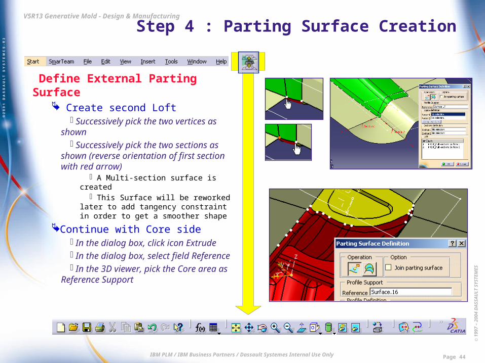
V5R13 Generative Mold - Design & Manufacturing Step 4 : Parting Surface Creation
Define External Parting Surface Create second Loft
Successively pick the two vertices as shown
Successively pick the two sections as shown (reverse orientation of first section with red arrow)
A Multi-section surface is created This Surface will be reworked later
to add tangency constraint in order to get a smoother shape
Continue with Core side In the dialog box, click icon Extrude In the dialog box, select field
Reference In the 3D viewer, pick the Core area
as Reference Support

© 1
997
– 20
04 D
ASS
AU
LT S
YSTE
MES
IBM PLM / IBM Business Partners / Dassault Systemes Internal Use Only Page 45
V5R13 Generative Mold - Design & Manufacturing Step 4 : Parting Surface Creation
Define External Parting Surface Create Extrude
Successively pick the two vertices as shown
The piece of boundary between the two vertices is highlighted in green
Pick the line of the prepared sketch as shown
An Extrude surface is created The sketch is located in the plane
orthogonal to the Main Pulling Direction
Validate creation of all surfaces Click OK in dialog box Parting
Surface Creation You can see that the corresponding
surfaces have been created as Extrude and Multi-sections Surface features

© 1
997
– 20
04 D
ASS
AU
LT S
YSTE
MES
IBM PLM / IBM Business Partners / Dassault Systemes Internal Use Only Page 46
V5R13 Generative Mold - Design & Manufacturing Step 4 : Parting Surface Creation
Define External Parting Surface Rework a previous surface to add
tangency Double-click the Multi-section surface
as shown In the dialog box, select line of
Section no.1 In the 3D viewer, pick the neighbour
Extrude Surface as shown Tangency constraint is added
Click OK to validate the modification
© 1
997
– 20
04 D
ASS
AU
LT S
YSTE
MES
IBM PLM / IBM Business Partners / Dassault Systemes Internal Use Only Page 47
V5R13 Generative Mold - Design & Manufacturing Step 4 : Parting Surface Creation
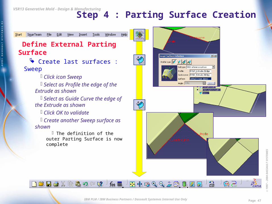
Define External Parting Surface Create last surfaces : Sweep
Click icon Sweep Select as Profile the edge of the
Extrude as shown Select as Guide Curve the edge of
the Extrude as shown Click OK to validate Create another Sweep surface as
shown The definition of the outer Parting
Surface is now complete
© 1
997
– 20
04 D
ASS
AU
LT S
YSTE
MES
IBM PLM / IBM Business Partners / Dassault Systemes Internal Use Only Page 48
V5R13 Generative Mold - Design & Manufacturing Step 4 : Parting Surface Creation
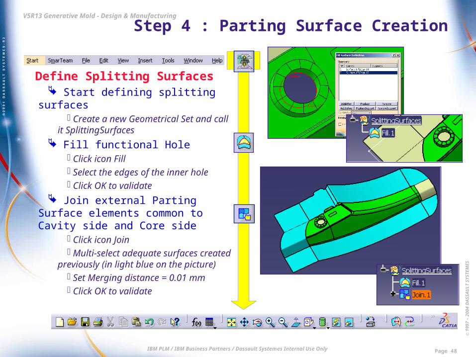
Define Splitting Surfaces Start defining splitting surfaces
Create a new Geometrical Set and call it SplittingSurfaces
Fill functional Hole Click icon Fill Select the edges of the inner hole Click OK to validate
Join external Parting Surface elements common to Cavity side and Core side
Click icon Join Multi-select adequate surfaces created
previously (in light blue on the picture) Set Merging distance = 0.01 mm Click OK to validate
© 1
997
– 20
04 D
ASS
AU
LT S
YSTE
MES
IBM PLM / IBM Business Partners / Dassault Systemes Internal Use Only Page 49
V5R13 Generative Mold - Design & Manufacturing Step 4 : Parting Surface Creation
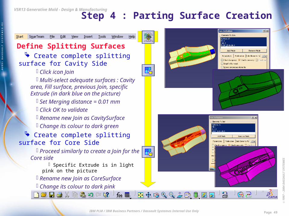
Define Splitting Surfaces Create complete splitting surface for
Cavity Side Click icon Join Multi-select adequate surfaces : Cavity
area, Fill surface, previous Join, specific Extrude (in dark blue on the picture)
Set Merging distance = 0.01 mm Click OK to validate Rename new Join as CavitySurface Change its colour to dark green
Create complete splitting surface for Core Side
Proceed similarly to create a Join for the Core side
Specific Extrude is in light pink on the picture
Rename new Join as CoreSurface Change its colour to dark pink

© 1
997
– 20
04 D
ASS
AU
LT S
YSTE
MES
IBM PLM / IBM Business Partners / Dassault Systemes Internal Use Only Page 50
V5R13 Generative Mold - Design & Manufacturing Step 4 : Parting Surface Creation
Define Splitting Surfaces Create complete splitting surface
for the Slider Click icon Join Multi-select adequate surfaces :
Slider area, specific Extrudes (in dark blue and light pink on the picture)
Set Merging distance = 0.01 mm Click OK to validate Rename new Join as SliderSurface Change its colour to bright yellow
Close without Save
End of Step 4. Result data is : \Step4-PartingSurfaceCreation\End\ MoldedPart.CATPart
© 1
997
– 20
04 D
ASS
AU
LT S
YSTE
MES
IBM PLM / IBM Business Partners / Dassault Systemes Internal Use Only Page 51
V5R13 Generative Mold - Design & Manufacturing Step 5 : Mold Tool Design
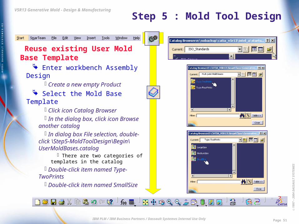
Reuse existing User Mold Base Template
Enter workbench Assembly Design Create a new empty Product
Select the Mold Base Template Click icon Catalog Browser In the dialog box, click icon Browse
another catalog In dialog box File selection, double-
click \Step5-MoldToolDesign\Begin\UserMoldBases.catalog
There are two categories of templates in the catalog
Double-click item named Type-TwoPrints
Double-click item named SmallSize

© 1
997
– 20
04 D
ASS
AU
LT S
YSTE
MES
IBM PLM / IBM Business Partners / Dassault Systemes Internal Use Only Page 52
V5R13 Generative Mold - Design & Manufacturing Step 5 : Mold Tool Design
Reuse existing User Mold Base Template
Create the Mold Base Double-click item named
TwoPrintsWithInserts Dialog box Insert Object is displayed,
showing the Product Template Click OK in dialog box Insert Object
A message informs you that the documents of the Template have been instantiated : the Mold Base Product, but also the prepared associated Drawing
Click OK to acknowledge the message Click Close in dialog box Catalog
Borowser The Mold Base Product is created Note that it already includes various
components : Leader Pins, Bushings, etc.

© 1
997
– 20
04 D
ASS
AU
LT S
YSTE
MES
IBM PLM / IBM Business Partners / Dassault Systemes Internal Use Only Page 53
V5R13 Generative Mold - Design & Manufacturing Step 5 : Mold Tool Design
Reuse existing User Mold Base Template
Close the Drawing Select Drawing document in the list of
open documents Do not update it and save it with a
meaningful name in a folder of your choice.
We will focus on the drawing in a next step
A message informs you that the corresponding Product is modified but not saved.
Click Yes in message dialog box. Another message lists the details of
unsaved Product and Parts files. Click Yes in message dialog box.
© 1
997
– 20
04 D
ASS
AU
LT S
YSTE
MES
IBM PLM / IBM Business Partners / Dassault Systemes Internal Use Only Page 54
V5R13 Generative Mold - Design & Manufacturing Step 5 : Mold Tool Design
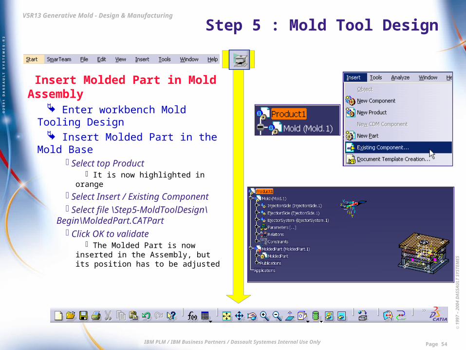
Insert Molded Part in Mold Assembly
Enter workbench Mold Tooling Design
Insert Molded Part in the Mold Base Select top Product
It is now highlighted in orange Select Insert / Existing Component Select file \Step5-MoldToolDesign\
Begin\MoldedPart.CATPart Click OK to validate
The Molded Part is now inserted in the Assembly, but its position has to be adjusted
© 1
997
– 20
04 D
ASS
AU
LT S
YSTE
MES
IBM PLM / IBM Business Partners / Dassault Systemes Internal Use Only Page 55
V5R13 Generative Mold - Design & Manufacturing Step 5 : Mold Tool Design
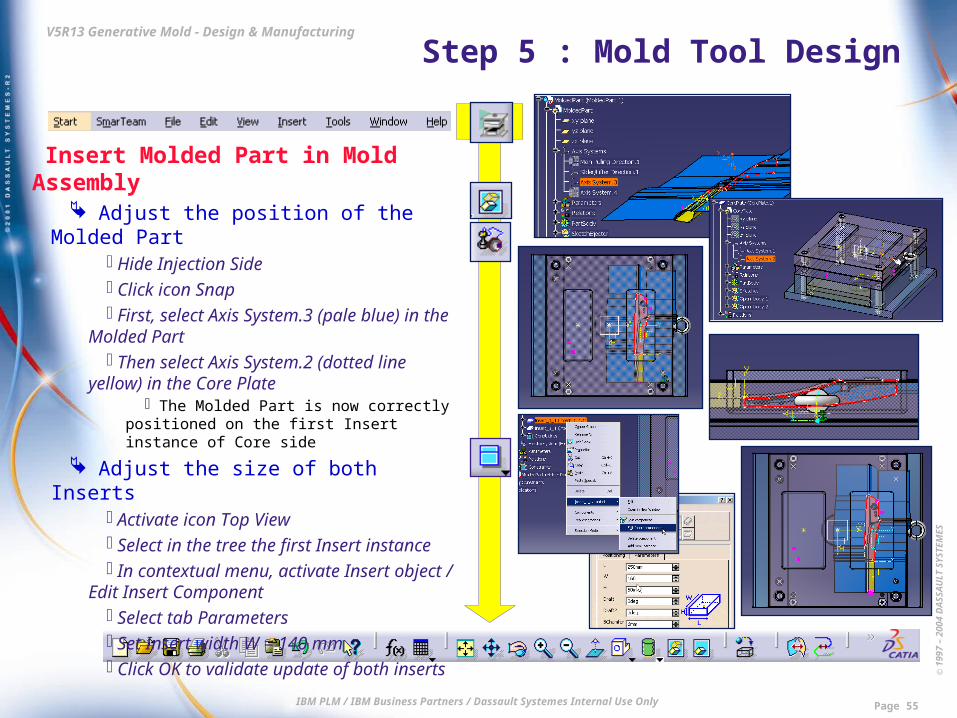
Insert Molded Part in Mold Assembly Adjust the position of the Molded Part
Hide Injection Side Click icon Snap First, select Axis System.3 (pale blue) in
the Molded Part Then select Axis System.2 (dotted line
yellow) in the Core Plate The Molded Part is now correctly
positioned on the first Insert instance of Core side
Adjust the size of both Inserts Activate icon Top View Select in the tree the first Insert instance In contextual menu, activate Insert
object / Edit Insert Component Select tab Parameters Set Insert width W = 140 mm Click OK to validate update of both
inserts
© 1
997
– 20
04 D
ASS
AU
LT S
YSTE
MES
IBM PLM / IBM Business Partners / Dassault Systemes Internal Use Only Page 56
V5R13 Generative Mold - Design & Manufacturing Step 5 : Mold Tool Design
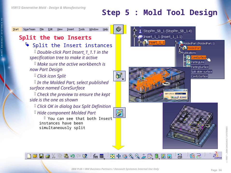
Split the two Inserts Split the Insert instances
Double-click Part Insert_1_1.1 in the specification tree to make it active
Make sure the active workbench is now Part Design
Click icon Split In the Molded Part, select published
surface named CoreSurface Check the preview to ensure the kept
side is the one as shown Click OK in dialog box Split Definition Hide component Molded Part
You can see that both Insert instances have been simultaneously split
© 1
997
– 20
04 D
ASS
AU
LT S
YSTE
MES
IBM PLM / IBM Business Partners / Dassault Systemes Internal Use Only Page 57
V5R13 Generative Mold - Design & Manufacturing Step 5 : Mold Tool Design
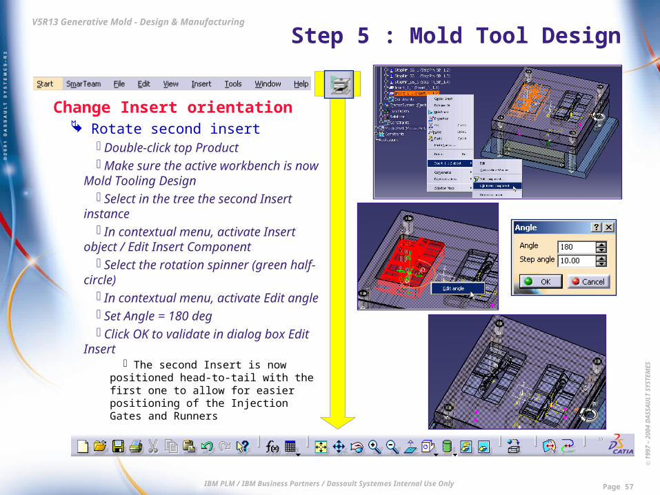
Change Insert orientation Rotate second insert
Double-click top Product Make sure the active workbench is
now Mold Tooling Design Select in the tree the second Insert
instance In contextual menu, activate Insert
object / Edit Insert Component Select the rotation spinner (green half-
circle) In contextual menu, activate Edit angle Set Angle = 180 deg Click OK to validate in dialog box Edit
Insert The second Insert is now positioned
head-to-tail with the first one to allow for easier positioning of the Injection Gates and Runners

© 1
997
– 20
04 D
ASS
AU
LT S
YSTE
MES
IBM PLM / IBM Business Partners / Dassault Systemes Internal Use Only Page 58
V5R13 Generative Mold - Design & Manufacturing Step 5 : Mold Tool Design
Create Ejectors Define Ejectors’ locations
Double-click any of the pink sketch points
The Sketcher is now active Zoom in onto one of the inserts Drag and drop the existing two points
to relocate them approximately as shown Zoom in onto the second insert to
check that the two other points of the sketch have automatically been adjusted
This is because these points have been created symmetrical to the first ones
Click icon Exit workbench Double-click top Product in the tree to
switch back to workbench Mold Tooling Design
© 1
997
– 20
04 D
ASS
AU
LT S
YSTE
MES
IBM PLM / IBM Business Partners / Dassault Systemes Internal Use Only Page 59
V5R13 Generative Mold - Design & Manufacturing Step 5 : Mold Tool Design
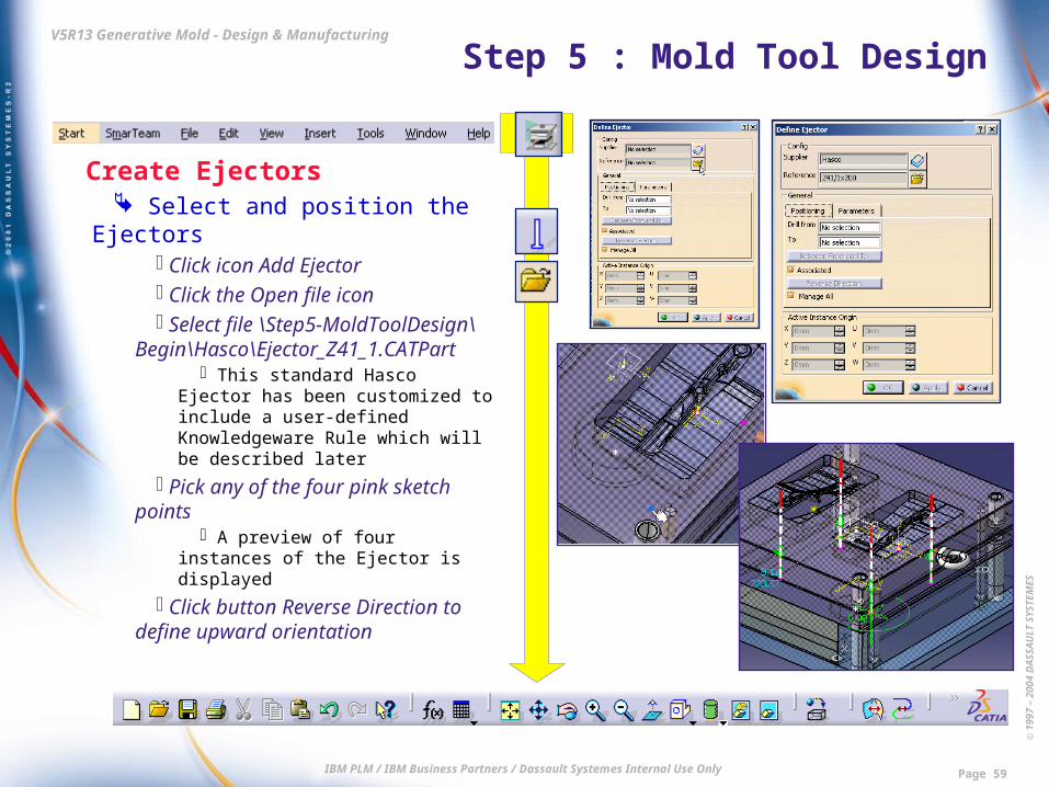
Create Ejectors Select and position the Ejectors
Click icon Add Ejector Click the Open file icon Select file \Step5-MoldToolDesign\
Begin\Hasco\Ejector_Z41_1.CATPart This standard Hasco Ejector has
been customized to include a user-defined Knowledgeware Rule which will be described later
Pick any of the four pink sketch points
A preview of four instances of the Ejector is displayed
Click button Reverse Direction to define upward orientation

© 1
997
– 20
04 D
ASS
AU
LT S
YSTE
MES
IBM PLM / IBM Business Partners / Dassault Systemes Internal Use Only Page 60
V5R13 Generative Mold - Design & Manufacturing Step 5 : Mold Tool Design
Create Ejectors Define Ejector drillings
In dialog box Define Ejector, check that field Drill From has automatically been set to EjectorPlateB (this is the plate containing the sketch)
Select field To in order to make it current
In the 3D viewer, pick the Insert Field To is automatically updated
Click button Between From and To In the 3D viewer, pick successively
CoreSupportPlate and CorePlate In dialog box Define All
Components to Cross, click OK to validate the list
© 1
997
– 20
04 D
ASS
AU
LT S
YSTE
MES
IBM PLM / IBM Business Partners / Dassault Systemes Internal Use Only Page 61
V5R13 Generative Mold - Design & Manufacturing Step 5 : Mold Tool Design
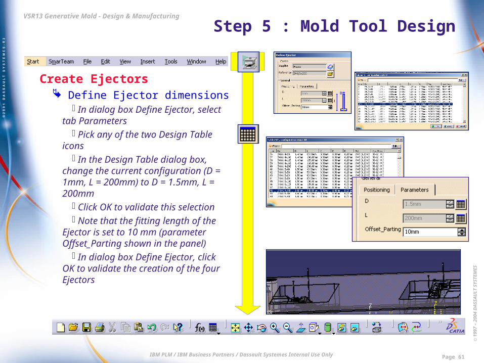
Create Ejectors Define Ejector dimensions
In dialog box Define Ejector, select tab Parameters
Pick any of the two Design Table icons
In the Design Table dialog box, change the current configuration (D = 1mm, L = 200mm) to D = 1.5mm, L = 200mm
Click OK to validate this selection Note that the fitting length of the
Ejector is set to 10 mm (parameter Offset_Parting shown in the panel)
In dialog box Define Ejector, click OK to validate the creation of the four Ejectors
© 1
997
– 20
04 D
ASS
AU
LT S
YSTE
MES
IBM PLM / IBM Business Partners / Dassault Systemes Internal Use Only Page 62
V5R13 Generative Mold - Design & Manufacturing Step 5 : Mold Tool Design
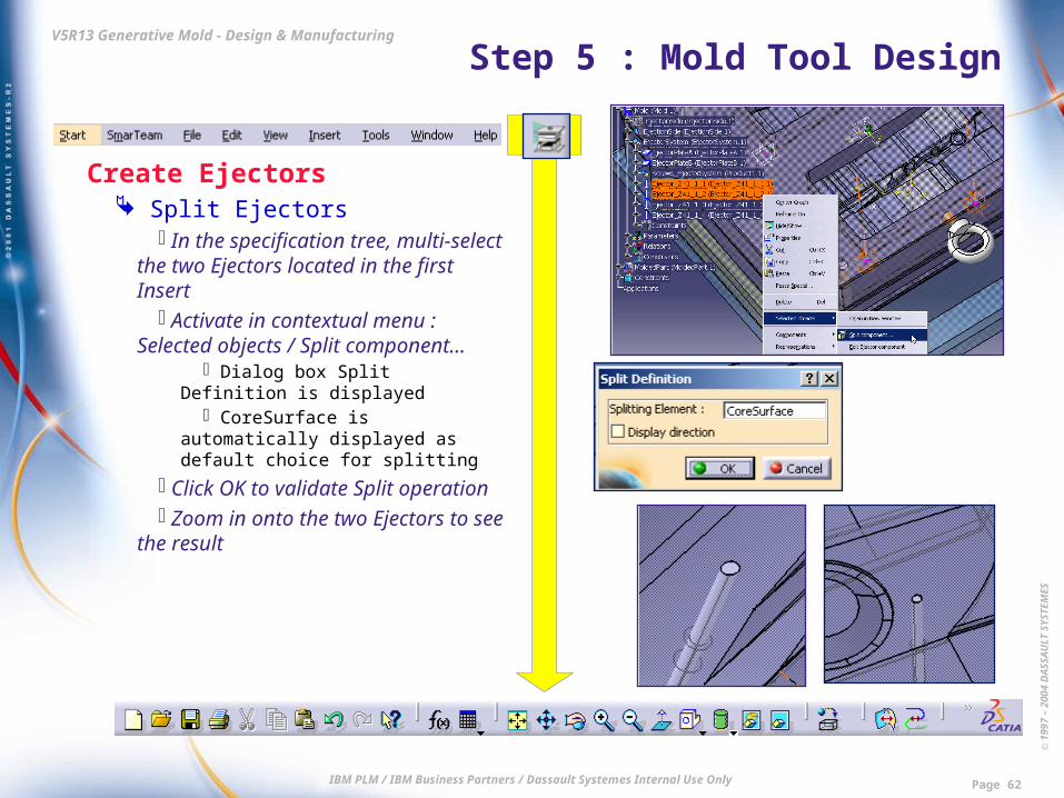
Create Ejectors Split Ejectors
In the specification tree, multi-select the two Ejectors located in the first Insert
Activate in contextual menu : Selected objects / Split component…
Dialog box Split Definition is displayed
CoreSurface is automatically displayed as default choice for splitting
Click OK to validate Split operation Zoom in onto the two Ejectors to
see the result
© 1
997
– 20
04 D
ASS
AU
LT S
YSTE
MES
IBM PLM / IBM Business Partners / Dassault Systemes Internal Use Only Page 63
V5R13 Generative Mold - Design & Manufacturing Step 5 : Mold Tool Design
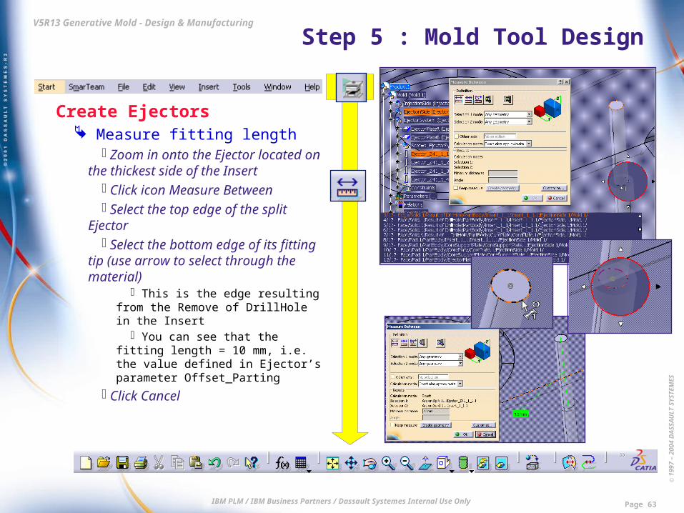
Create Ejectors Measure fitting length
Zoom in onto the Ejector located on the thickest side of the Insert
Click icon Measure Between Select the top edge of the split
Ejector Select the bottom edge of its fitting
tip (use arrow to select through the material)
This is the edge resulting from the Remove of DrillHole in the Insert
You can see that the fitting length = 10 mm, i.e. the value defined in Ejector’s parameter Offset_Parting
Click Cancel

© 1
997
– 20
04 D
ASS
AU
LT S
YSTE
MES
IBM PLM / IBM Business Partners / Dassault Systemes Internal Use Only Page 64
V5R13 Generative Mold - Design & Manufacturing Step 5 : Mold Tool Design
Create Ejectors Show Knowledgeware Rule to
adjust the fitting length In the specification tree, unfold node
Relations of the Ejector Part Highlight Knowledgeware Rule named
FittingLengthComputation Double-click it once to activate
workbench Knowledge Advisor Double-click it again to open the Rule
Editor dialog box and display the content of the Rule
This Rule enables to adjust the fitting length of the ejector to value Offset_Parting whatever the location of the Ejector
Click OK to close the Rule Editor dialog box
Double-click the top Product in the tree to switch back to workbench Mold Tooling Design

© 1
997
– 20
04 D
ASS
AU
LT S
YSTE
MES
IBM PLM / IBM Business Partners / Dassault Systemes Internal Use Only Page 65
V5R13 Generative Mold - Design & Manufacturing Step 5 : Mold Tool Design
Create Ejectors Change Ejector location
Select again the same Ejector in the tree
In contextual menu, activate Ejector object / Edit component
Click icon Top View Use the green arrow spinners to
drag the Ejector to the bottom of the pocket as shown
Click OK to validate the new location
Click icon Measure Between Select the top and bottom edges as
done previously You can see that the clearance hole
of the Ejector has been adjusted to keep the fitting tip length at 10 mm
© 1
997
– 20
04 D
ASS
AU
LT S
YSTE
MES
IBM PLM / IBM Business Partners / Dassault Systemes Internal Use Only Page 66
V5R13 Generative Mold - Design & Manufacturing Step 5 : Mold Tool Design
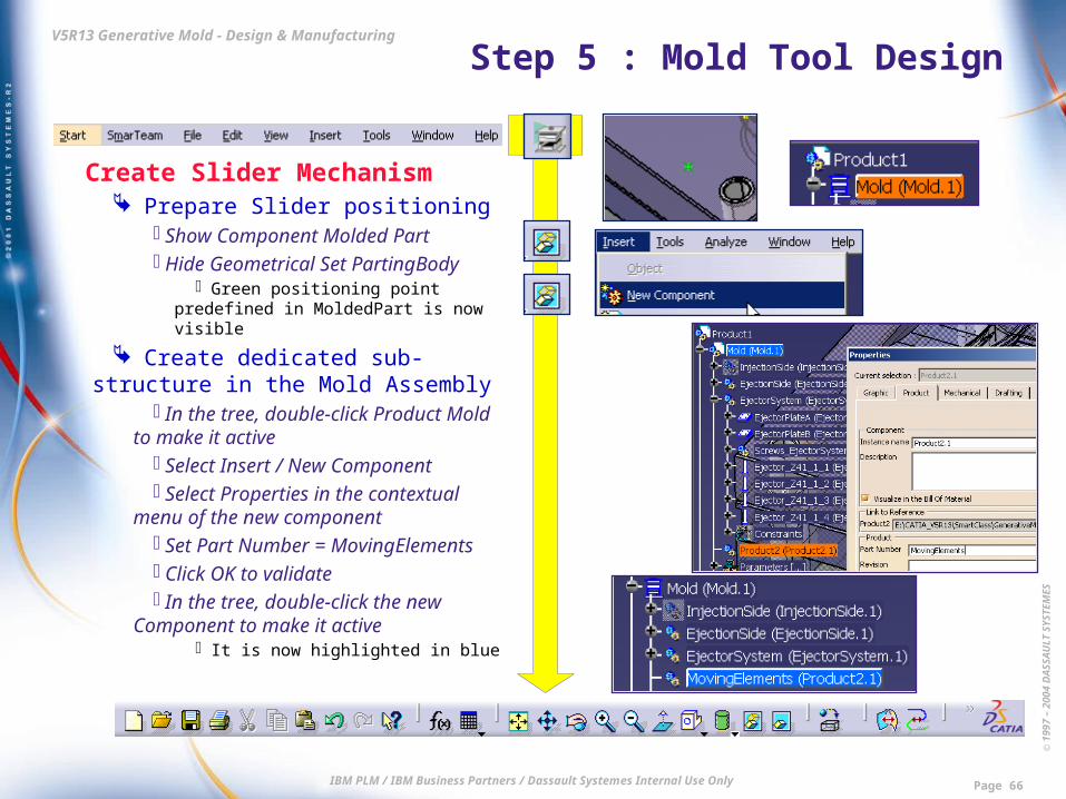
Create Slider Mechanism Prepare Slider positioning
Show Component Molded Part Hide Geometrical Set PartingBody
Green positioning point predefined in MoldedPart is now visible
Create dedicated sub-structure in the Mold Assembly
In the tree, double-click Product Mold to make it active
Select Insert / New Component Select Properties in the contextual
menu of the new component Set Part Number = MovingElements Click OK to validate In the tree, double-click the new
Component to make it active It is now highlighted in blue

© 1
997
– 20
04 D
ASS
AU
LT S
YSTE
MES
IBM PLM / IBM Business Partners / Dassault Systemes Internal Use Only Page 67
V5R13 Generative Mold - Design & Manufacturing Step 5 : Mold Tool Design
Create Slider Mechanism Select Slider Assembly
Click icon Add User Component Click the Open file icon Select file \Step5-MoldToolDesign\
Begin\SliderAssembly\DressedSlider.CATProduct
Define Slider position Pick green positioning point
predefined in MoldedPart A preview of the Slider Assembly is
displayed Use the green arc spinner to define
a 90-deg rotation The Slider assembly preview should
now look as shown
© 1
997
– 20
04 D
ASS
AU
LT S
YSTE
MES
IBM PLM / IBM Business Partners / Dassault Systemes Internal Use Only Page 68
V5R13 Generative Mold - Design & Manufacturing Step 5 : Mold Tool Design
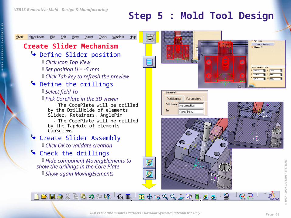
Create Slider Mechanism Define Slider position
Click icon Top View Set position U = -5 mm Click Tab key to refresh the preview
Define the drillings Select field To Pick CorePlate in the 3D viewer
The CorePlate will be drilled by the DrillHolde of elements Slider, Retainers, AnglePin
The CorePlate will be drilled by the TapHole of elements CapScrews
Create Slider Assembly Click OK to validate creation
Check the drillings Hide component MovingElements to
show the drillings in the Core Plate Show again MovingElements
© 1
997
– 20
04 D
ASS
AU
LT S
YSTE
MES
IBM PLM / IBM Business Partners / Dassault Systemes Internal Use Only Page 69
V5R13 Generative Mold - Design & Manufacturing Step 5 : Mold Tool Design
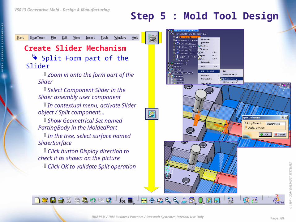
Create Slider Mechanism Split Form part of the Slider
Zoom in onto the form part of the Slider
Select Component Slider in the Slider assembly user component
In contextual menu, activate Slider object / Split component…
Show Geometrical Set named PartingBody in the MoldedPart
In the tree, select surface named SliderSurface
Click button Display direction to check it as shown on the picture
Click OK to validate Split operation

© 1
997
– 20
04 D
ASS
AU
LT S
YSTE
MES
IBM PLM / IBM Business Partners / Dassault Systemes Internal Use Only Page 70
V5R13 Generative Mold - Design & Manufacturing Step 5 : Mold Tool Design
Create Slider Mechanism Final check
Hide PartingBody The form part of the Slider now fits
the undercut area Close without Save
End of Step 5. Result data is : \Step5-MoldToolDesign\End\
Product1.CATProduct
© 1
997
– 20
04 D
ASS
AU
LT S
YSTE
MES
IBM PLM / IBM Business Partners / Dassault Systemes Internal Use Only Page 71
V5R13 Generative Mold - Design & Manufacturing Step 6 : Mold Tool Drawings
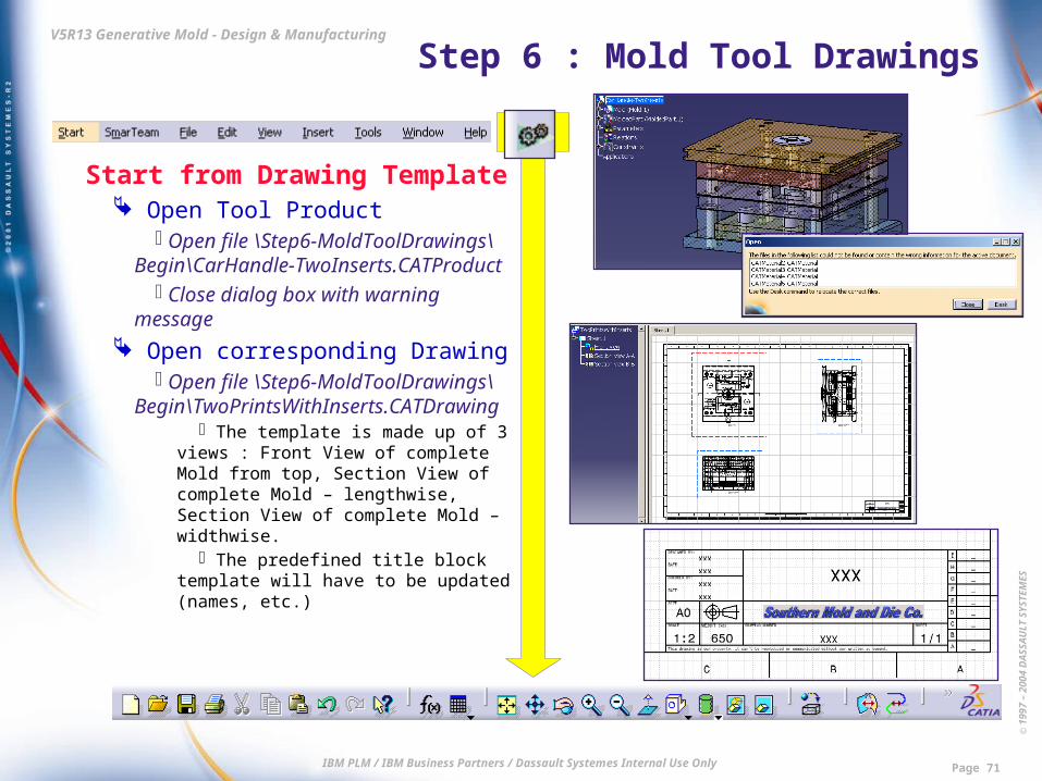
Start from Drawing Template Open Tool Product
Open file \Step6-MoldToolDrawings\Begin\CarHandle-TwoInserts.CATProduct
Close dialog box with warning message
Open corresponding Drawing Open file \Step6-MoldToolDrawings\
Begin\TwoPrintsWithInserts.CATDrawing The template is made up of 3 views :
Front View of complete Mold from top, Section View of complete Mold – lengthwise, Section View of complete Mold – widthwise.
The predefined title block template will have to be updated (names, etc.)

© 1
997
– 20
04 D
ASS
AU
LT S
YSTE
MES
IBM PLM / IBM Business Partners / Dassault Systemes Internal Use Only Page 72
V5R13 Generative Mold - Design & Manufacturing Step 6 : Mold Tool Drawings
Create the Bill of Material Automatic numbering of the Parts
Select the Product in the list of open documents
Switch to workbench Assembly Design
In the specification tree, double-click Product Mold
It is now highlighted in orange Click icon Generate Numbering Keep default values (Mode =
Integer) Click OK to validate numbering
operation Create the Bill of Material
Select Analyze / Bill Of Material
© 1
997
– 20
04 D
ASS
AU
LT S
YSTE
MES
IBM PLM / IBM Business Partners / Dassault Systemes Internal Use Only Page 73
V5R13 Generative Mold - Design & Manufacturing Step 6 : Mold Tool Drawings
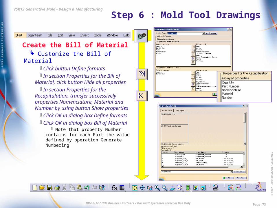
Create the Bill of Material Customize the Bill of Material
Click button Define formats In section Properties for the Bill of
Material, click button Hide all properties In section Properties for the
Recapitulation, transfer successively properties Nomenclature, Material and Number by using button Show properties
Click OK in dialog box Define formats
Click OK in dialog box Bill of Material
Note that property Number contains for each Part the value defined by operation Generate Numbering

© 1
997
– 20
04 D
ASS
AU
LT S
YSTE
MES
IBM PLM / IBM Business Partners / Dassault Systemes Internal Use Only Page 74
V5R13 Generative Mold - Design & Manufacturing Step 6 : Mold Tool Drawings
Create the Bill of Material Insert the Generative BOM in the
Drawing Select Window / Tile Horizontally Select the Drawing window Activate contextual menu of Sheet.1
and select Activate Sheet Select Insert / Generation / Bill of
Material Select node Mold in the
specification tree of the Product Pick in the Drawing Sheet the
location where you want to insert the BOM
Zoom in to check the content of the BOM

© 1
997
– 20
04 D
ASS
AU
LT S
YSTE
MES
IBM PLM / IBM Business Partners / Dassault Systemes Internal Use Only Page 75
V5R13 Generative Mold - Design & Manufacturing Step 6 : Mold Tool Drawings
Complete the Drawing Update the Title Block
Select Edit / Background Double-click the text frame of the
drawing title and change initial value xxx to Car Handle
Click OK in dialog box Text Editor Select Edit / Working Views
Global change in the definition of Section View
Select Section View B-B In its contextual menu, select Edit
Properties Uncheck option Hidden Lines Click OK to validate
The View is automatically updated

© 1
997
– 20
04 D
ASS
AU
LT S
YSTE
MES
IBM PLM / IBM Business Partners / Dassault Systemes Internal Use Only Page 76
V5R13 Generative Mold - Design & Manufacturing Step 6 : Mold Tool Drawings
Complete the Drawing Change Section View Profile
Double-click the profile defining Section B-B
Click icon Replace Profile Create a new profile approximately
as shown Click icon End Profile Edition
The Section View is automatically updated
© 1
997
– 20
04 D
ASS
AU
LT S
YSTE
MES
IBM PLM / IBM Business Partners / Dassault Systemes Internal Use Only Page 77
V5R13 Generative Mold - Design & Manufacturing Step 6 : Mold Tool Drawings
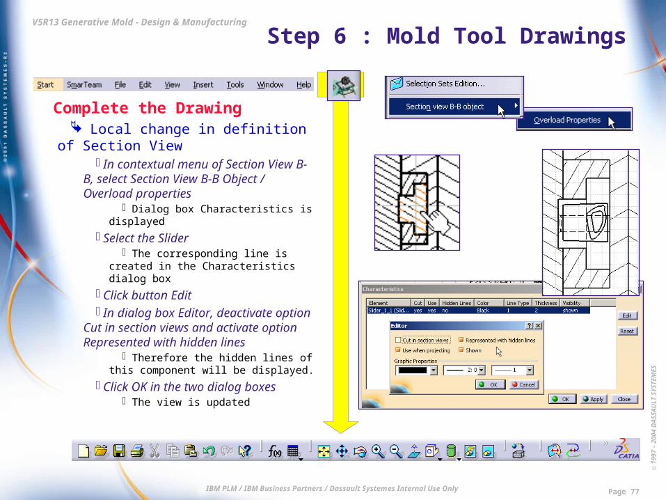
Complete the Drawing Local change in definition of
Section View In contextual menu of Section View
B-B, select Section View B-B Object / Overload properties
Dialog box Characteristics is displayed
Select the Slider The corresponding line is created in
the Characteristics dialog box Click button Edit In dialog box Editor, deactivate
option Cut in section views and activate option Represented with hidden lines
Therefore the hidden lines of this component will be displayed.
Click OK in the two dialog boxes The view is updated

© 1
997
– 20
04 D
ASS
AU
LT S
YSTE
MES
IBM PLM / IBM Business Partners / Dassault Systemes Internal Use Only Page 78
V5R13 Generative Mold - Design & Manufacturing Step 6 : Mold Tool Drawings
Complete the Drawing Create Balloons
Click icon Generate Balloons Arrange the position of some
overlapping balloons Close without Save
End of Step 6. Result data is : \Step6-MoldToolDrawings\End\
TwoPrintsWithInserts.CATDrawing

© 1
997
– 20
04 D
ASS
AU
LT S
YSTE
MES
IBM PLM / IBM Business Partners / Dassault Systemes Internal Use Only Page 79
V5R13 Generative Mold - Design & Manufacturing Step 7 : 2.5- & 3-Axis Manufacturing
Start Manufacturing of one Insert Start from existing Machining
Process Open file \Step7-Manufacturing\
Begin\Template_3X-roughing.CATProcess
Select Product to be machined In the PPR tree, double-click Part
Operation In dialog box Part Operation, click
icon Product or Part Select file \Step7-Manufacturing\
Begin\Product_for_demonstration.CATProduct

© 1
997
– 20
04 D
ASS
AU
LT S
YSTE
MES
IBM PLM / IBM Business Partners / Dassault Systemes Internal Use Only Page 80
V5R13 Generative Mold - Design & Manufacturing Step 7 : 2.5- & 3-Axis Manufacturing
Define Roughing Operations Select Part to be machined
In dialog box Part Operation, click icon Design part for simulation
Double-click the Insert in the 3D viewer
Define rough stock In dialog box Part Operation, click
icon Stock In PPR tree, double-click Part
Body of the Part named STOCK This is the rough Pad defining the
Insert, before the Insert is split with the form surfaces
© 1
997
– 20
04 D
ASS
AU
LT S
YSTE
MES
IBM PLM / IBM Business Partners / Dassault Systemes Internal Use Only Page 81
V5R13 Generative Mold - Design & Manufacturing Step 7 : 2.5- & 3-Axis Manufacturing
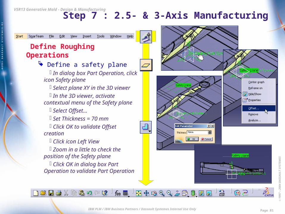
Define Roughing Operations Define a safety plane
In dialog box Part Operation, click icon Safety plane
Select plane XY in the 3D viewer In the 3D viewer, activate
contextual menu of the Safety plane Select Offset… Set Thickness = 70 mm Click OK to validate Offset
creation Click icon Left View Zoom in a little to check the
position of the Safety plane Click OK in dialog box Part
Operation to validate Part Operation

© 1
997
– 20
04 D
ASS
AU
LT S
YSTE
MES
IBM PLM / IBM Business Partners / Dassault Systemes Internal Use Only Page 82
V5R13 Generative Mold - Design & Manufacturing Step 7 : 2.5- & 3-Axis Manufacturing
Define Roughing Operations Define areas to be machined
Click icon Manufacturing View In dialog box Manufacturing View,
activate in contextual menu : Manufacturing View object / Sort by Machinable Features
Double-click item Part to be machined
In dialog box Zone : Areas, click the sensitive area
In the 3D viewer, first select the Insert (Part Body), then Filling Surfaces (Geometrical Set)
Double-click in the background to get dialog box Zone : Areas back
Click OK in dialog box Zone : Areas

© 1
997
– 20
04 D
ASS
AU
LT S
YSTE
MES
IBM PLM / IBM Business Partners / Dassault Systemes Internal Use Only Page 83
V5R13 Generative Mold - Design & Manufacturing Step 7 : 2.5- & 3-Axis Manufacturing
Define Roughing Operations Define limiting contour
In dialog box Manufacturing View, double-click item Limiting Contour Definition
In dialog box Zone : Lines, click the sensitive edge area
In toolbar Edge Selection, click icon Display option panel
In dialog box Options, make sure that Link types = Line insert
Pick successively the four corner edges of the Insert to get a result as shown
In toolbar Edge Selection, click icon Close Contour with Line to close the contour
Click OK in toolbar Edge Selection Click OK in dialog box Zone : Lines Click Close in dialog box Manufacturing
View Use Save As to store CATProcess in
another folder of your choice

© 1
997
– 20
04 D
ASS
AU
LT S
YSTE
MES
IBM PLM / IBM Business Partners / Dassault Systemes Internal Use Only Page 84
V5R13 Generative Mold - Design & Manufacturing Step 7 : 2.5- & 3-Axis Manufacturing
Define Roughing Operations Define computation in batch
mode Click icon Manage Batch Queue In dialog box NC Batch
Management, click icon New job In dialog box Job definition, click
icon “…” In the PPR tree, select 3-Axis
PROGRAM In dialog box Job definition, click
OK to validate
© 1
997
– 20
04 D
ASS
AU
LT S
YSTE
MES
IBM PLM / IBM Business Partners / Dassault Systemes Internal Use Only Page 85
V5R13 Generative Mold - Design & Manufacturing Step 7 : 2.5- & 3-Axis Manufacturing
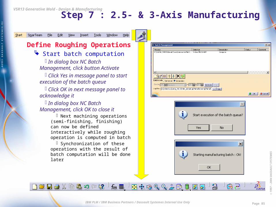
Define Roughing Operations Start batch computation
In dialog box NC Batch Management, click button Activate
Click Yes in message panel to start execution of the batch queue
Click OK in next message panel to acknowledge it
In dialog box NC Batch Management, click OK to close it
Next machining operations (semi-finishing, finishing) can now be defined interactively while roughing operation is computed in batch
Synchronization of these operations with the result of batch computation will be done later

© 1
997
– 20
04 D
ASS
AU
LT S
YSTE
MES
IBM PLM / IBM Business Partners / Dassault Systemes Internal Use Only Page 86
V5R13 Generative Mold - Design & Manufacturing Step 7 : 2.5- & 3-Axis Manufacturing
Define Semi-finishing Operations Define Slope area
Click icon Machining/Slope Area Activate contextual menu of
sensitive area named Part Activate Select zones In dialog box Zone Selection, select
line Part to be machined Click right-arrow button to transfer it
to list Selected Click OK to validate selection In dialog box Machining Area,
activate option Slope Area Select tab Slope Area Select T3Ball-Nose D16 as
Reference Tool Set Lower Angle = 47 deg Set Overlap = 1 mm
© 1
997
– 20
04 D
ASS
AU
LT S
YSTE
MES
IBM PLM / IBM Business Partners / Dassault Systemes Internal Use Only Page 87
V5R13 Generative Mold - Design & Manufacturing Step 7 : 2.5- & 3-Axis Manufacturing
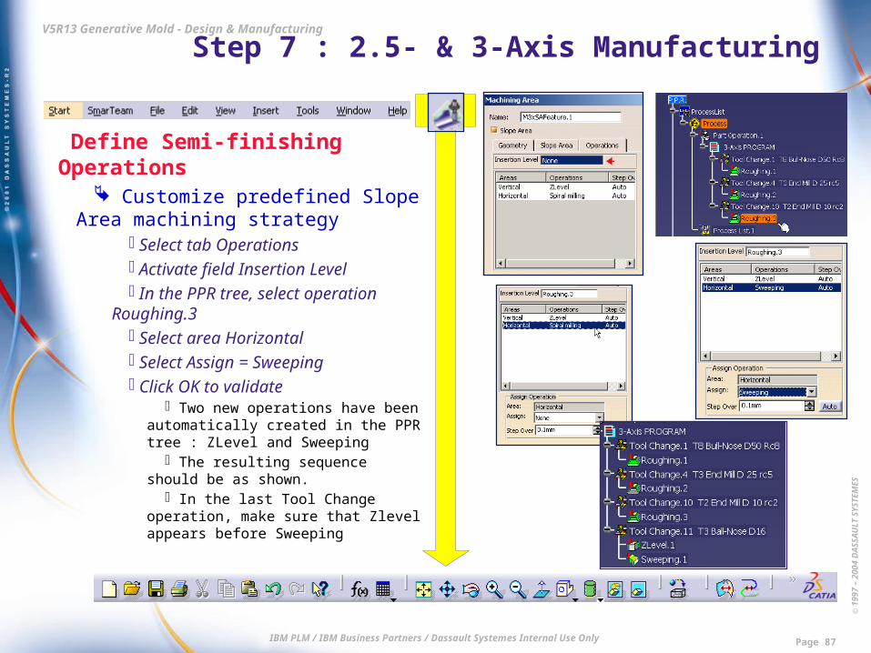
Define Semi-finishing Operations Customize predefined Slope Area
machining strategy Select tab Operations Activate field Insertion Level In the PPR tree, select operation
Roughing.3 Select area Horizontal Select Assign = Sweeping Click OK to validate
Two new operations have been automatically created in the PPR tree : ZLevel and Sweeping
The resulting sequence should be as shown.
In the last Tool Change operation, make sure that Zlevel appears before Sweeping

© 1
997
– 20
04 D
ASS
AU
LT S
YSTE
MES
IBM PLM / IBM Business Partners / Dassault Systemes Internal Use Only Page 88
V5R13 Generative Mold - Design & Manufacturing Step 7 : 2.5- & 3-Axis Manufacturing
Define Semi-finishing Operations Compute Tool paths
In the PPR tree, multi-select operations ZLevel and Sweeping
Click icon Tool Path Replay Both tool paths are successively
computed and displayed
Simulate Tool path In dialog box Sweeping.1, click icon
Go to start of tool path Click icon Forward replay
Simulation of the ZLevel operation begins

© 1
997
– 20
04 D
ASS
AU
LT S
YSTE
MES
IBM PLM / IBM Business Partners / Dassault Systemes Internal Use Only Page 89
V5R13 Generative Mold - Design & Manufacturing Step 7 : 2.5- & 3-Axis Manufacturing
Define Semi-finishing Operations Simulate Tool path
After a few seconds, click icon Display complete tool path
The simulation now runs until the end of the Sweeping operation
Click OK in dialog box Sweeping to close it
© 1
997
– 20
04 D
ASS
AU
LT S
YSTE
MES
IBM PLM / IBM Business Partners / Dassault Systemes Internal Use Only Page 90
V5R13 Generative Mold - Design & Manufacturing Step 7 : 2.5- & 3-Axis Manufacturing
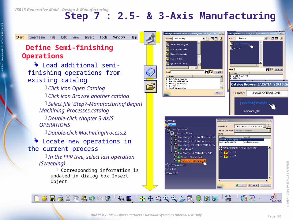
Define Semi-finishing Operations Load additional semi-finishing
operations from existing catalog Click icon Open Catalog Click icon Browse another catalog Select file \Step7-Manufacturing\
Begin\Machining_Processes.catalog Double-click chapter 3-AXIS
OPERATIONS Double-click MachiningProcess.2
Locate new operations in the current process
In the PPR tree, select last operation (Sweeping)
Corresponding information is updated in dialog box Insert Object

© 1
997
– 20
04 D
ASS
AU
LT S
YSTE
MES
IBM PLM / IBM Business Partners / Dassault Systemes Internal Use Only Page 91
V5R13 Generative Mold - Design & Manufacturing Step 7 : 2.5- & 3-Axis Manufacturing
Define Semi-finishing Operations Define geometry to apply loaded
operations Click icon Manufacturing View Select Pencil Semi-Finishing
Corresponding information is updated in dialog box Insert Object
Click OK in dialog box Insert Object Click Close in dialog box Catalog
Browser Click Close in dialog box
Manufacturing View Check the PPR tree : two new
operations have been inserted (Pencil.1 and Pencil.2)
Compute tool paths Multi-select the two Pencil operations Click icon Tool Path Replay
Both Tool Paths are now computed Click OK in dialog box Pencil.2

© 1
997
– 20
04 D
ASS
AU
LT S
YSTE
MES
IBM PLM / IBM Business Partners / Dassault Systemes Internal Use Only Page 92
V5R13 Generative Mold - Design & Manufacturing Step 7 : 2.5- & 3-Axis Manufacturing
Define Finishing Operations Define Rework operations
Click icon Rework area In dialog box Rework Area, click
button Load from Select Sweeping.1 in the PPR tree
Sensitive area Part has turned green in dialog box Rework Area
Click tab Other in dialog box Rework Area
Set tolerance = 0.02 mm Select tab Operations Select field Insertion Level Select Pencil2 in the PPR tree Select Tool Reference = T5 Ball-
Nose D4 Click OK to validate definition Check the PPR tree : two new
operations have been inserted : Contour-driven.1 and ZLevel.2

© 1
997
– 20
04 D
ASS
AU
LT S
YSTE
MES
IBM PLM / IBM Business Partners / Dassault Systemes Internal Use Only Page 93
V5R13 Generative Mold - Design & Manufacturing Step 7 : 2.5- & 3-Axis Manufacturing
Define Finishing Operations Define Rework operations
In the PPR tree, double-click operation Contour-driven.1 to edit it
In dialog box Contour-driven, set Machining tolerance = 0.03 mm
Click OK to validate Similarly, edit operation Zlevel.2 to
also set Machining tolerance = 0.03 mm Compute Tool Path
Multi-select operations Contour-driven.1 and ZLevel.2
Click icon Tool Path Replay Both Tool Paths are now computed

© 1
997
– 20
04 D
ASS
AU
LT S
YSTE
MES
IBM PLM / IBM Business Partners / Dassault Systemes Internal Use Only Page 94
V5R13 Generative Mold - Design & Manufacturing Step 7 : 2.5- & 3-Axis Manufacturing
Define Finishing Operations Visualize computed Tool Path
In dialog box ZLevel.2, click icon Go to start of tool path
Click icon Forward replay Simulation of the Contour-driven
operation begins After a few seconds, click OK in
simulation dialog box to end the dynamic visualization
© 1
997
– 20
04 D
ASS
AU
LT S
YSTE
MES
IBM PLM / IBM Business Partners / Dassault Systemes Internal Use Only Page 95
V5R13 Generative Mold - Design & Manufacturing Step 7 : 2.5- & 3-Axis Manufacturing
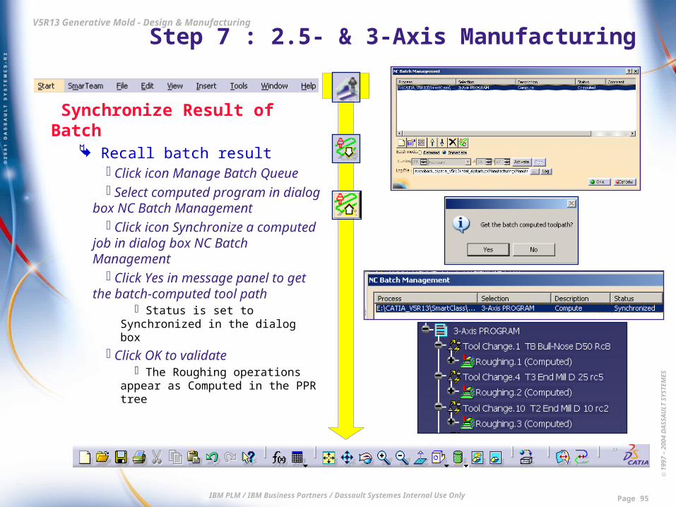
Synchronize Result of Batch Recall batch result
Click icon Manage Batch Queue Select computed program in dialog
box NC Batch Management Click icon Synchronize a computed
job in dialog box NC Batch Management
Click Yes in message panel to get the batch-computed tool path
Status is set to Synchronized in the dialog box
Click OK to validate The Roughing operations appear
as Computed in the PPR tree

© 1
997
– 20
04 D
ASS
AU
LT S
YSTE
MES
IBM PLM / IBM Business Partners / Dassault Systemes Internal Use Only Page 96
V5R13 Generative Mold - Design & Manufacturing Step 7 : 2.5- & 3-Axis Manufacturing
Check Results Check Roughing operations with
video simulation Select operation Roughing.3 in the
PPR tree Click icon Tool Path Replay
Result appears instantly In dialog box Roughing.3, click
icon Video from last saved result Click icon Forward replay Move the speed cursor far right to
accelerate the simulation All three Roughing operations are
successively displayed After a while, click OK to end
dynamic visualization
© 1
997
– 20
04 D
ASS
AU
LT S
YSTE
MES
IBM PLM / IBM Business Partners / Dassault Systemes Internal Use Only Page 97
V5R13 Generative Mold - Design & Manufacturing Step 7 : 2.5- & 3-Axis Manufacturing
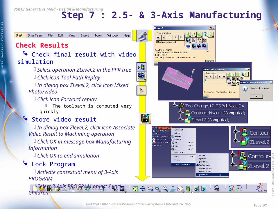
Check Results Check final result with video simulation
Select operation ZLevel.2 in the PPR tree
Click icon Tool Path Replay In dialog box ZLevel.2, click icon Mixed
Photo/Video Click icon Forward replay
The toolpath is computed very quickly
Store video result In dialog box Zlevel.2, click icon
Associate Video Result to Machining operation
Click OK in message box Manufacturing Information
Click OK to end simulation Lock Program
Activate contextual menu of 3-Axis PROGRAM
Select 3-Axis PROGRAM object / Lock Children

© 1
997
– 20
04 D
ASS
AU
LT S
YSTE
MES
IBM PLM / IBM Business Partners / Dassault Systemes Internal Use Only Page 98
V5R13 Generative Mold - Design & Manufacturing Step 7 : 2.5- & 3-Axis Manufacturing
Define Drilling Operations Create new Manufacturing Program
Click icon Manufacturing Program In the PPR tree, select 3-Axis
PROGRAM The new program is inserted after it
Activate Hole features Double-click Part Insert_1 in the viewer
New current workbench is Part Design In PartBody, activate contextual menu of
Remove feature ExplodedHoles This feature has automatically been
created before in workbench Mold Tooling Design thanks to function Tools/Explode Holes which has converted the original individual Remove features into features of type Hole
Select ExplodedHoles object / Activate Zoom in to briefly review the holes
There are holes coming from Cooling pipes, Screws and Ejectors
© 1
997
– 20
04 D
ASS
AU
LT S
YSTE
MES
IBM PLM / IBM Business Partners / Dassault Systemes Internal Use Only Page 99
V5R13 Generative Mold - Design & Manufacturing Step 7 : 2.5- & 3-Axis Manufacturing
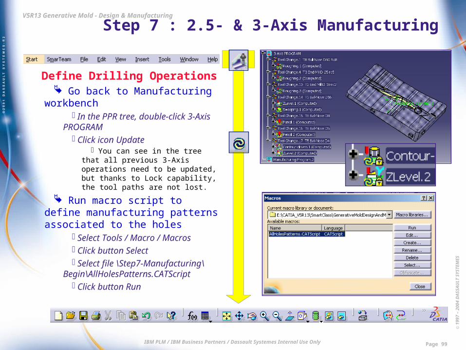
Define Drilling Operations Go back to Manufacturing
workbench In the PPR tree, double-click 3-
Axis PROGRAM Click icon Update
You can see in the tree that all previous 3-Axis operations need to be updated, but thanks to Lock capability, the tool paths are not lost.
Run macro script to define manufacturing patterns associated to the holes
Select Tools / Macro / Macros Click button Select Select file \Step7-Manufacturing\
Begin\AllHolesPatterns.CATScript Click button Run

© 1
997
– 20
04 D
ASS
AU
LT S
YSTE
MES
IBM PLM / IBM Business Partners / Dassault Systemes Internal Use Only Page 100
V5R13 Generative Mold - Design & Manufacturing Step 7 : 2.5- & 3-Axis Manufacturing
Define Drilling Operations Run macro script to define
manufacturing patterns associated to the holes
Click OK in message panel requesting Part selection
Select the Insert in the 3D Viewer Click OK to acknowledge the
message displayed to confirm selection Click OK to acknowledge the
message indicating the end of execution Check the result
Click icon Manufacturing View Activate in contextual menu :
Manufacturing View object / Sort by Patterns
A Machining Pattern has been created for each type of Hole

© 1
997
– 20
04 D
ASS
AU
LT S
YSTE
MES
IBM PLM / IBM Business Partners / Dassault Systemes Internal Use Only Page 101
V5R13 Generative Mold - Design & Manufacturing Step 7 : 2.5- & 3-Axis Manufacturing
Define Drilling Operations Load drilling operations from
existing catalog Click icon Open Catalog Double-click chapter DRILLING
Define drilling for the first Cooling pipe
Double-click item Machining Process.1
In the PPR tree, select newly created Manufacturing program
Insertion level information is updated in dialog box Insert Object
In the Manufacturing View, select the last pattern whose name is Holes_Diam10_Blind_Counterbored
Click OK in dialog box Insert Object
© 1
997
– 20
04 D
ASS
AU
LT S
YSTE
MES
IBM PLM / IBM Business Partners / Dassault Systemes Internal Use Only Page 102
V5R13 Generative Mold - Design & Manufacturing Step 7 : 2.5- & 3-Axis Manufacturing
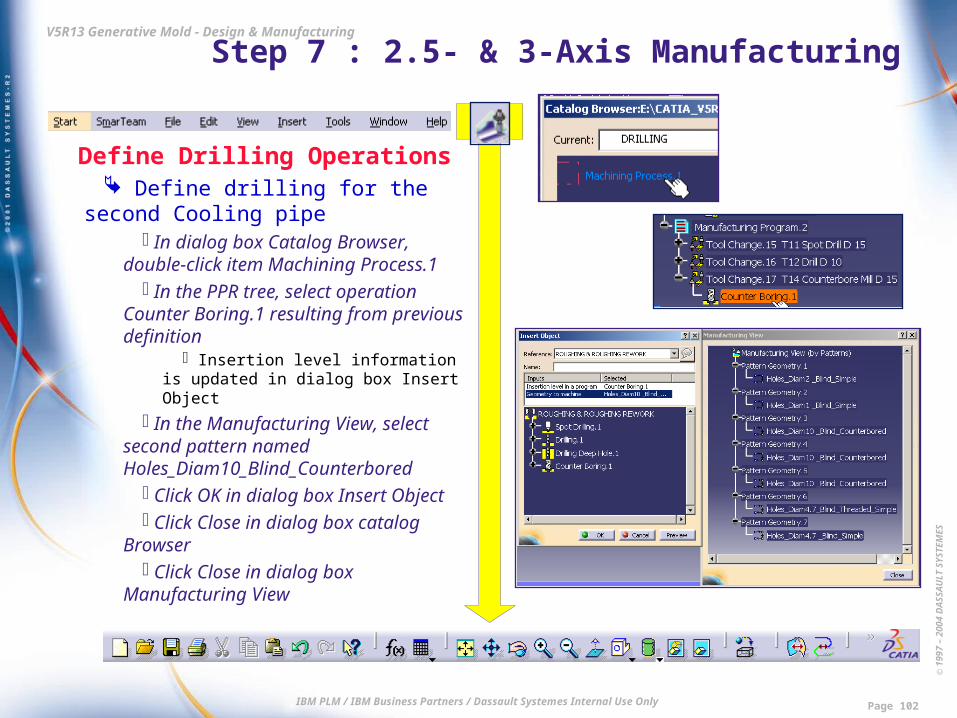
Define Drilling Operations Define drilling for the second
Cooling pipe In dialog box Catalog Browser,
double-click item Machining Process.1 In the PPR tree, select operation
Counter Boring.1 resulting from previous definition
Insertion level information is updated in dialog box Insert Object
In the Manufacturing View, select second pattern named Holes_Diam10_Blind_Counterbored
Click OK in dialog box Insert Object Click Close in dialog box catalog
Browser Click Close in dialog box
Manufacturing View

© 1
997
– 20
04 D
ASS
AU
LT S
YSTE
MES
IBM PLM / IBM Business Partners / Dassault Systemes Internal Use Only Page 103
V5R13 Generative Mold - Design & Manufacturing Step 7 : 2.5- & 3-Axis Manufacturing
Define Drilling Operations Compute the tool paths
In the PPR tree, multi-select all the operations defined in Manufacturing Program.2
In contextual menu, activate Compute Tool Path
Click OK in dialog box Computation mode
Click OK in message dialog box to acknowledge the warning message
All tool paths are now computed

© 1
997
– 20
04 D
ASS
AU
LT S
YSTE
MES
IBM PLM / IBM Business Partners / Dassault Systemes Internal Use Only Page 104
V5R13 Generative Mold - Design & Manufacturing Step 7 : 2.5- & 3-Axis Manufacturing
Define Drilling Operations Display the tool paths
In the PPR tree, multi-select the last three operations defined in Manufacturing Program.2
Click icon Tool Path Replay In dialog box Counter Boring.2, click
icon Go to start of tool path Click icon Forward replay
Simulation of operation SpotDrilling.2 begins
After a few seconds, move the speed cursor right to accelerate simulation
All operations are successively displayed
When the simulation is finished, click OK in dialog box Counter Boring.2

© 1
997
– 20
04 D
ASS
AU
LT S
YSTE
MES
IBM PLM / IBM Business Partners / Dassault Systemes Internal Use Only Page 105
V5R13 Generative Mold - Design & Manufacturing Step 7 : 2.5- & 3-Axis Manufacturing
Define Drilling Operations Minimize the number of tool
changes In the PPR tree, select Manufacturing
Program.2 Click icon Auto Sequence Deactivate all options except the first
one : Sort by operation type Click OK in dialog box Auto Sequence In the PPR tree, review the new
sequencing

© 1
997
– 20
04 D
ASS
AU
LT S
YSTE
MES
IBM PLM / IBM Business Partners / Dassault Systemes Internal Use Only Page 106
V5R13 Generative Mold - Design & Manufacturing Step 7 : 2.5- & 3-Axis Manufacturing
Define Drilling Operations Check final result with Video
simulation In the PPR tree, select last operation :
Counter Boring.2 Click icon Tool Path Replay In dialog box Counter Boring.2, click icon
Video from last saved result Click icon Forward replay After a few seconds, move the speed
cursor right to accelerate the simulation When simulation is finished, click OK in
dialog box Counter Boring.2 Close without Save
End of Step 7 Result data of Step 7 : \Step7-Manufacturing\End\CompleteMachining.CATProcess


