Download - Mohr Circle
1
COMBINED AXIAL AND SHEARING STRESS
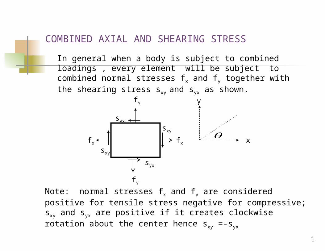
In general when a body is subject to combined loadings , every element will be subject to combined normal stresses fx and fy together with the shearing stress sxy and syx as shown.
fy
syx
syx
sxy
sxy
fxfx x
y
Note: normal stresses fx and fy are considered positive for tensile stress negative for compressive; sxy and syx are positive if it creates clockwise rotation about the center hence sxy =-syx
fy
2
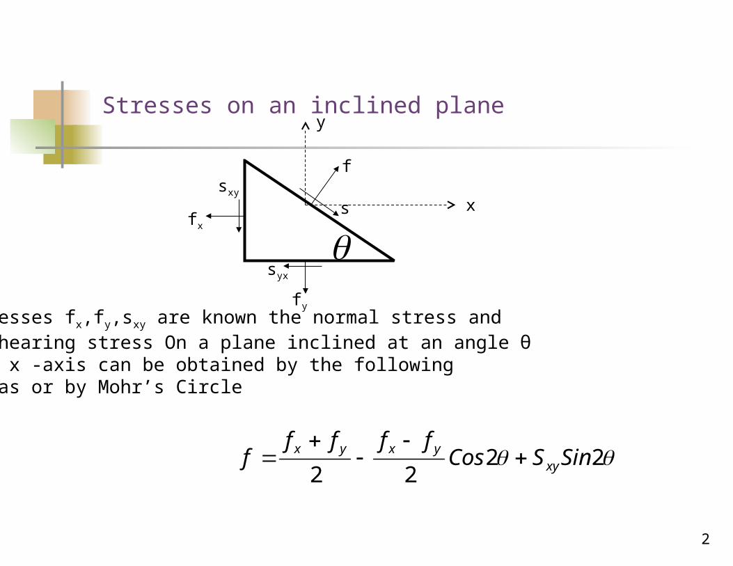
Stresses on an inclined plane
fx
sxy
fy
syx
s
f
x
y
If stresses fx,fy,sxy are known the normal stress and the shearing stress On a plane inclined at an angle θ to the x -axis can be obtained by the followingformulas or by Mohr’s Circle
2222
SinSCosffff
f xyyxyx
3
222
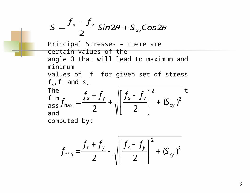
CosSSinff
S xyyx
Principal Stresses – there are certain values of the angle θ that will lead to maximum and minimum values of f for given set of stress fx,fy and sxy. These maximum and minimum values that f may assume are termed principal stresses and can be computed by:
2
2
max )(22 xy
yxyx Sffff
f
2
2
min )(22 xy
yxyx Sffff
f
4
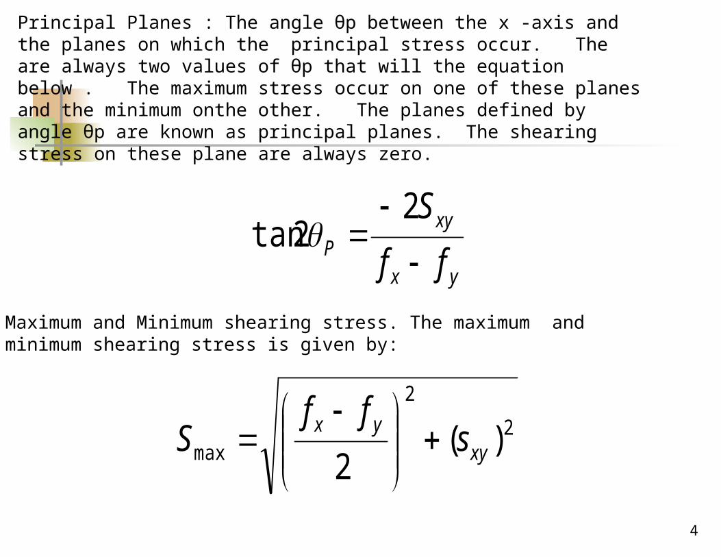
Principal Planes : The angle θp between the x -axis and the planes on which the principal stress occur. The are always two values of θp that will the equation below . The maximum stress occur on one of these planes and the minimum onthe other. The planes defined by angle θp are known as principal planes. The shearing stress on these plane are always zero.
yx
xyP ff
S
22tan
Maximum and Minimum shearing stress. The maximum and minimum shearing stress is given by:
2
2
max )(2 xy
yx sff
S
5
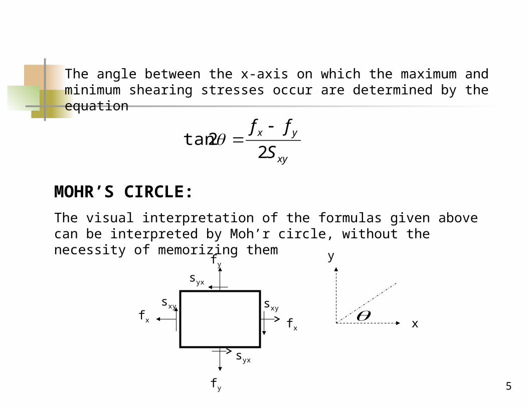
The angle between the x-axis on which the maximum and minimum shearing stresses occur are determined by the equation
xy
yx
S
ff
22tan
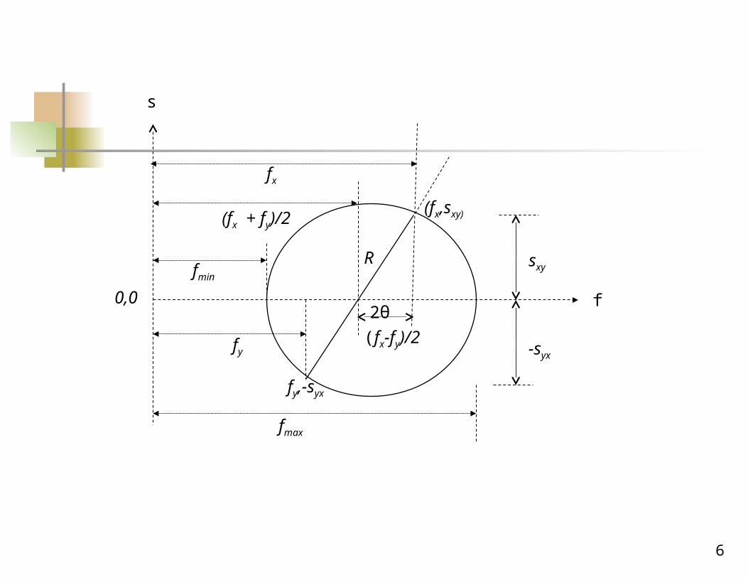
MOHR’S CIRCLE:
The visual interpretation of the formulas given above can be interpreted by Moh’r circle, without the necessity of memorizing them
fy
syx
fy
fx
syx
sxysxy
fx
y
x
6
(fx,sxy)
fy,-syx
fmax
fmin
(fx + fy)/2
fy
fx
(fx-fy)/2
R
2θ f
s
sxy
-syx
0,0
7
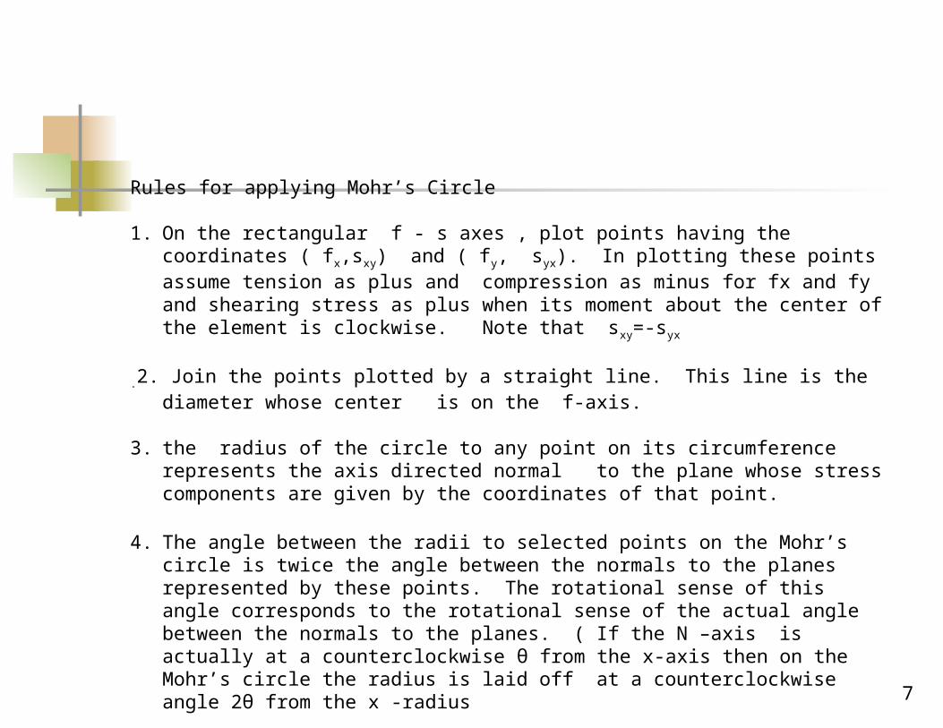
Rules for applying Mohr’s Circle
1. On the rectangular f - s axes , plot points having the coordinates ( fx,sxy) and ( fy, syx). In plotting these points assume tension as plus and compression as minus for fx and fy and shearing stress as plus when its moment about the center of the element is clockwise. Note that sxy=-syx
.2. Join the points plotted by a straight line. This line is the diameter whose center is on the f-axis.
3. the radius of the circle to any point on its circumference represents the axis directed normal to the plane whose stress components are given by the coordinates of that point.
4. The angle between the radii to selected points on the Mohr’s circle is twice the angle between the normals to the planes represented by these points. The rotational sense of this angle corresponds to the rotational sense of the actual angle between the normals to the planes. ( If the N –axis is actually at a counterclockwise θ from the x-axis then on the Mohr’s circle the radius is laid off at a counterclockwise angle 2θ from the x -radius
8
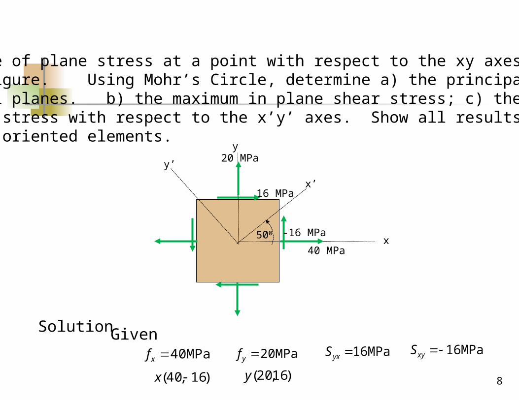
Problem:The state of plane stress at a point with respect to the xy axes is as shown In the figure. Using Mohr’s Circle, determine a) the principal stress and principal planes. b) the maximum in plane shear stress; c) the equivalent state of stress with respect to the x’y’ axes. Show all results on sketches ofproperly oriented elements.
MPa 40xf MPa 20yf MPa 16yxS MPa 16xyS
)16,40( x )16,20(y
x
y20 MPa
40 MPa
16 MPa
Solution Given
-16 MPa500
x’
y’
9
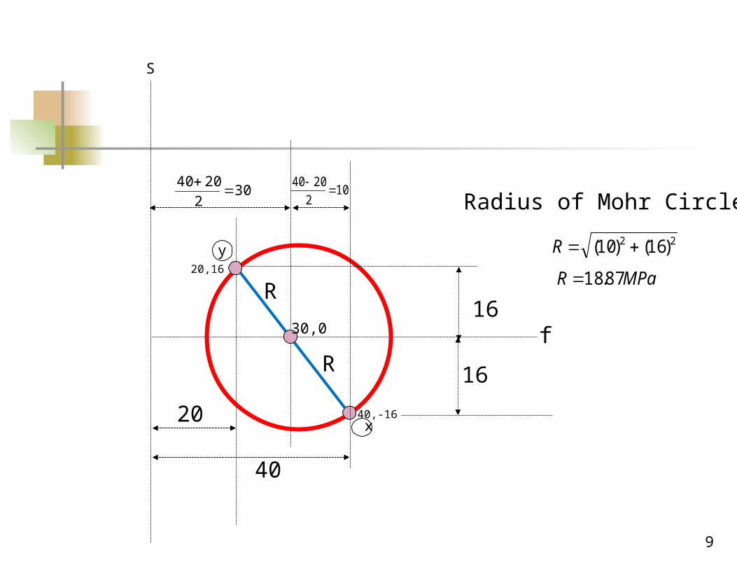
f
S
40,-16
20,16
x
y
40
20
302
2040
10
2
2040
16
1630,0
Radius of Mohr Circle
22 )16()10( R
MPaR 87.18
R
R
1010
f
S
x
y
40
20
30 10
16
16
18.87
18.87
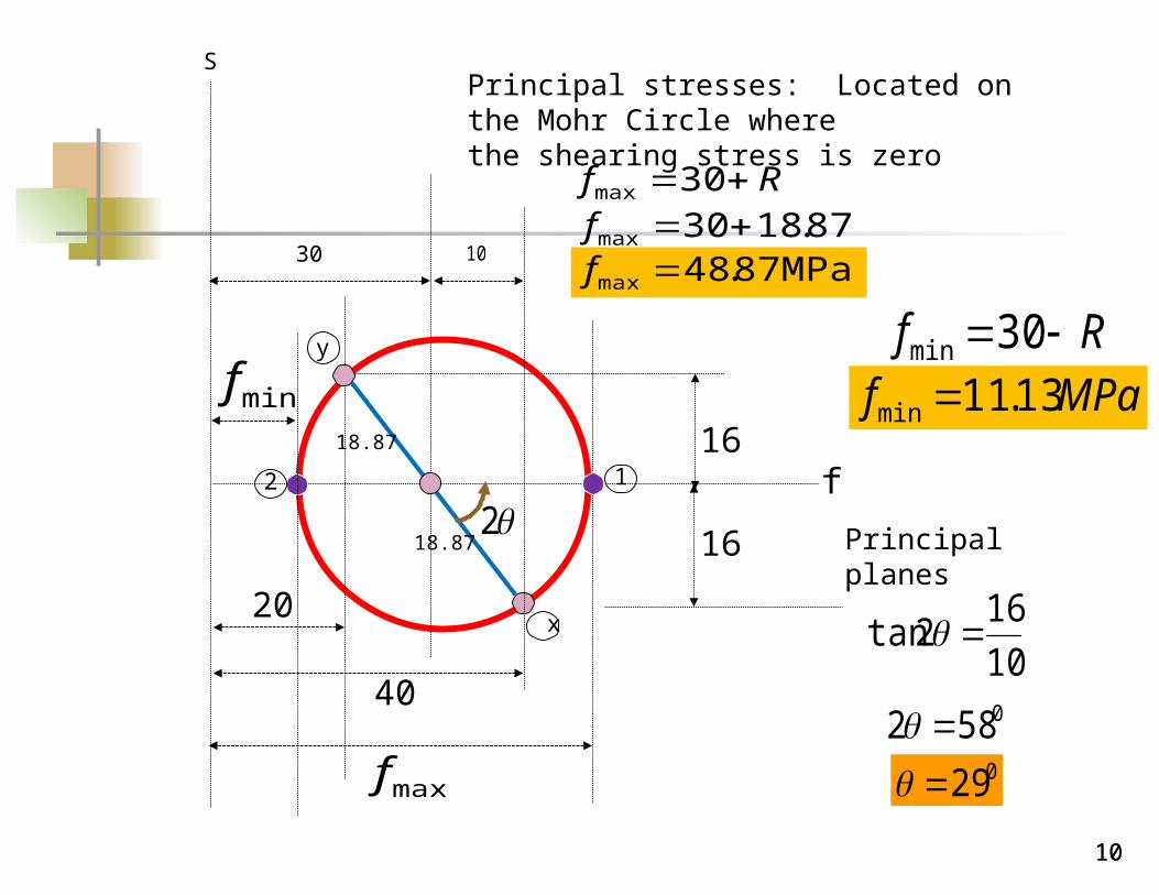
Principal stresses: Located on the Mohr Circle wherethe shearing stress is zero
maxf
minf
Rf 30max
87.1830max fMPa 87.48max f
Rf 30min
MPaf 13.11min
Principal planes 2
10
162tan
0582 029
12
f
S
x
y
40
20
30 10
16
16
18.87
18.87
2
a
b
1
211.13 MPa
48.87 MPa
290
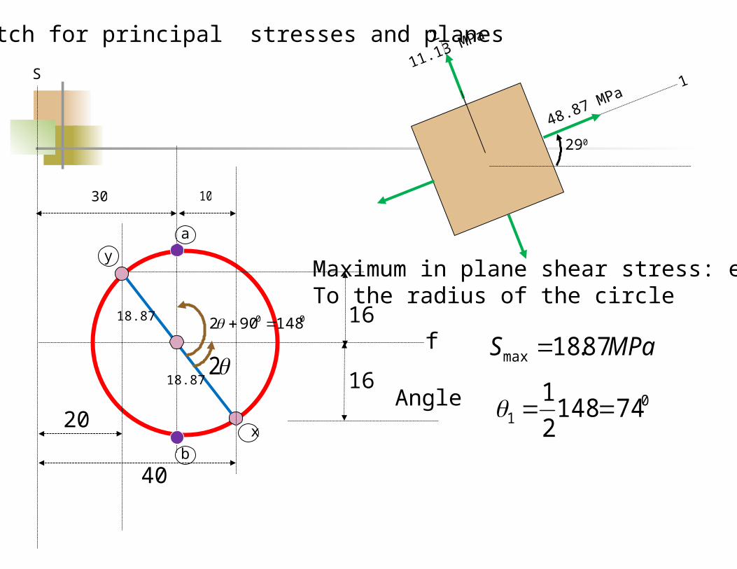
00 148902
Sketch for principal stresses and planes
Maximum in plane shear stress: equalTo the radius of the circle
MPaS 87.18max
Angle 01 74148
2
1
12
a30 MPa
30 MPa
740
18 .87MPa
18.87 MPa
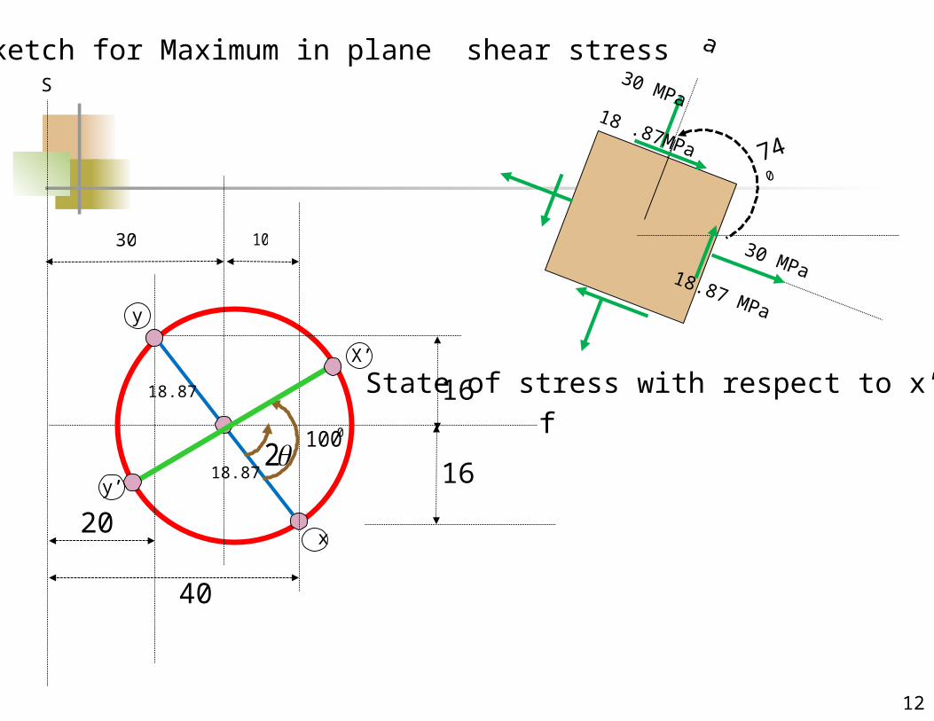
Sketch for Maximum in plane shear stress
f
S
x
y
40
20
30 10
16
16
18.87
18.87
2
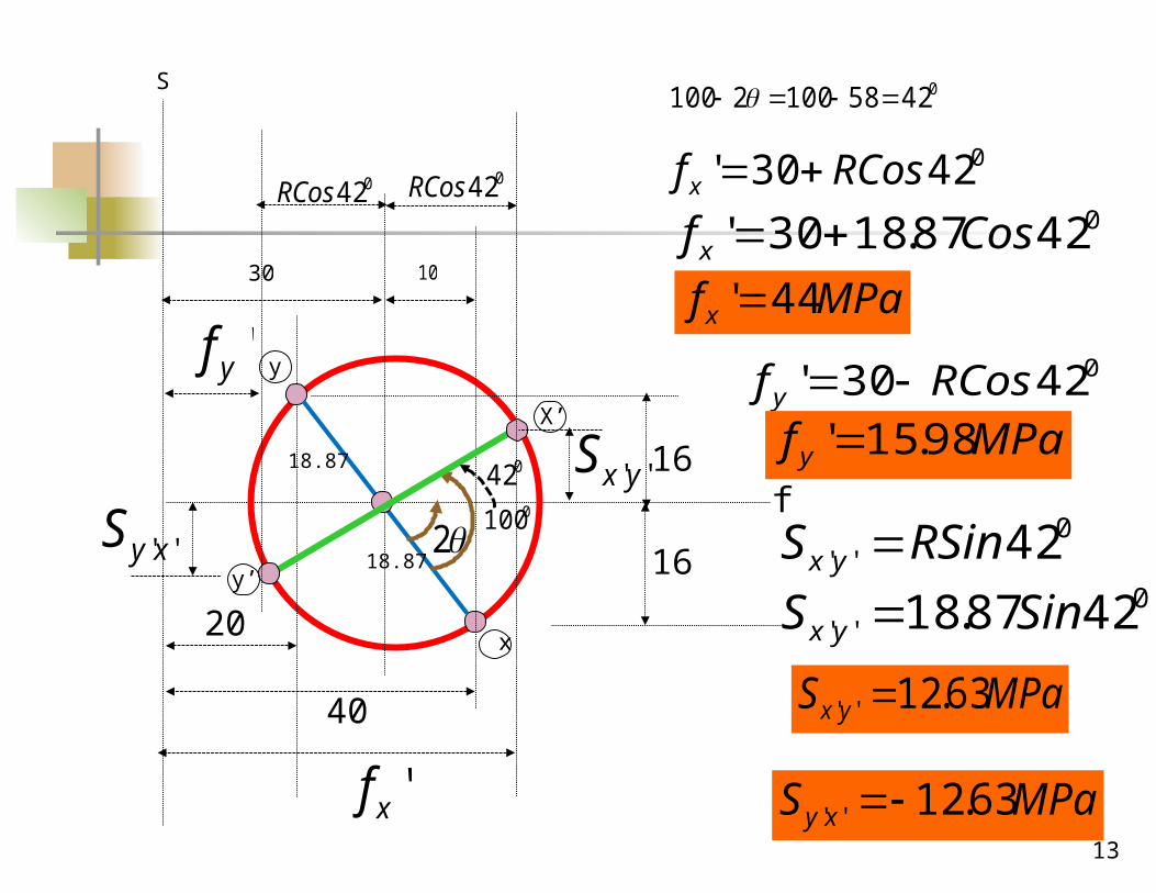
State of stress with respect to x’y’ axes
0100
X’
y’
13
f
S
x
y
40
20
30 10
16
16
18.87
18.87
20100
X’
y’
042581002100
042
042RCos042RCos
'xf
'yf
''yxS
''xyS
04230' RCosf x 04287.1830' Cosf x
MPaf x 44'04230' RCosf y
MPaf y 98.15'
0'' 42RSinS yx
0'' 4287.18 SinS yx
MPaS yx 63.12''
MPaS xy 63.12''
14
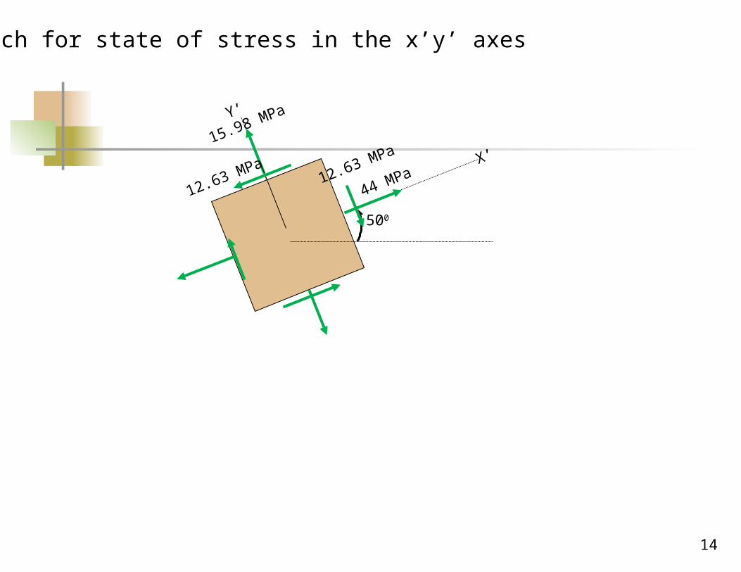
X’
Y’
15.98 MPa
44 MPa
500
12.63 MPa 12.63 MPa
Sketch for state of stress in the x’y’ axes
15
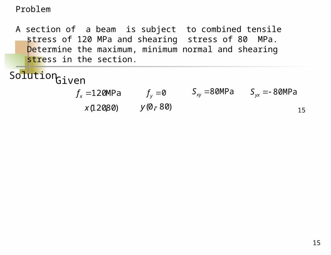
Problem
A section of a beam is subject to combined tensile stress of 120 MPa and shearing stress of 80 MPa. Determine the maximum, minimum normal and shearing stress in the section.
15
MPa 120xf 0yf MPa 80xyS MPa 80yxS
)80,120(x )80,0( y
Solution Given
16
f
S
y
120,80
0,-80
x
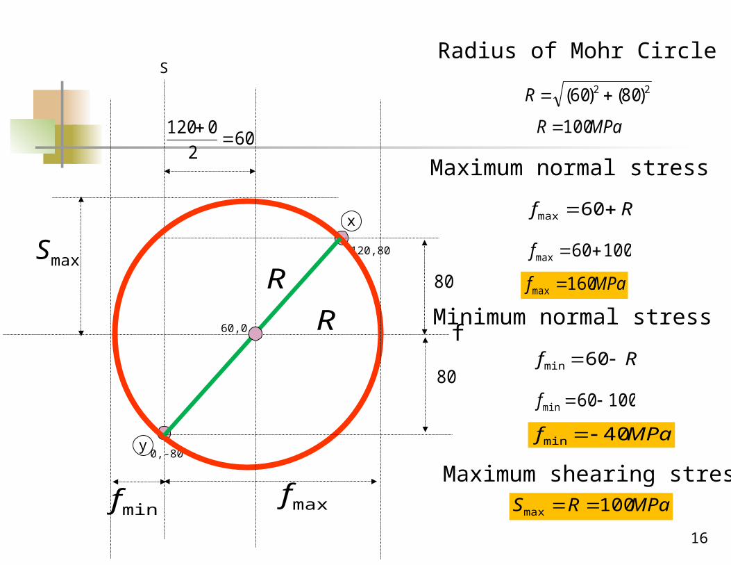
602
0120
60,0
maxfminf
maxS80
80
Radius of Mohr Circle
22 )80()60( R
MPaR 100
R
R
Maximum normal stress
Rf 60max
10060max f
MPaf 160max
Minimum normal stress
Rf 60min
10060min f
MPaf 40min
Maximum shearing stressMPaRS 100max
17
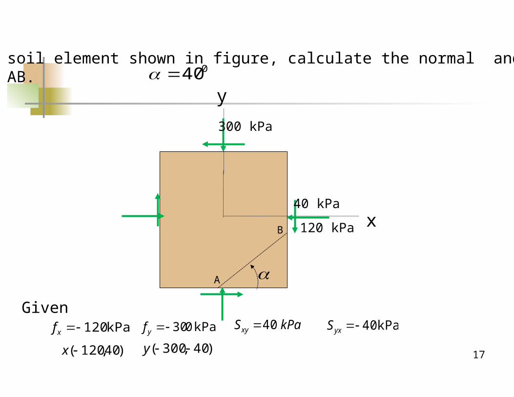
ProblemFor the soil element shown in figure, calculate the normal and shear stresson plane AB.
x
y
300 kPa
120 kPa
40 kPa
A
B
kPa 120xf kPa 030yf kPaSxy 40 kPa 40yxS
)40,120(x )40,300( y
Given
040
f
Ssolution
(-120,40)x
(-300,-40)y
2102
)300120(
(-210,0)
40
40
2
0802
A
B
ABf
ABS
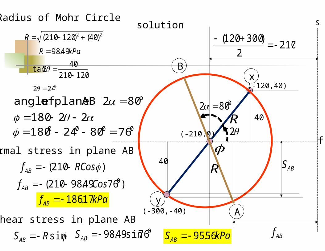
Radius of Mohr Circle
22 )40()120210( R
kPaR 49.98
R
R
120210
402tan
0242
22180
802 AB plane of angle o
0000 768024180
Normal stress in plane AB
)210( RCosfAB
)7649.98210( 0CosfAB kPafAB 17.186
Shear stress in plane AB
sinRSAB 076sin49.98ABS kPaSAB 56.95
19
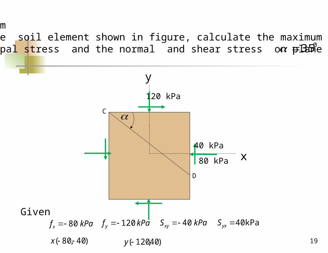
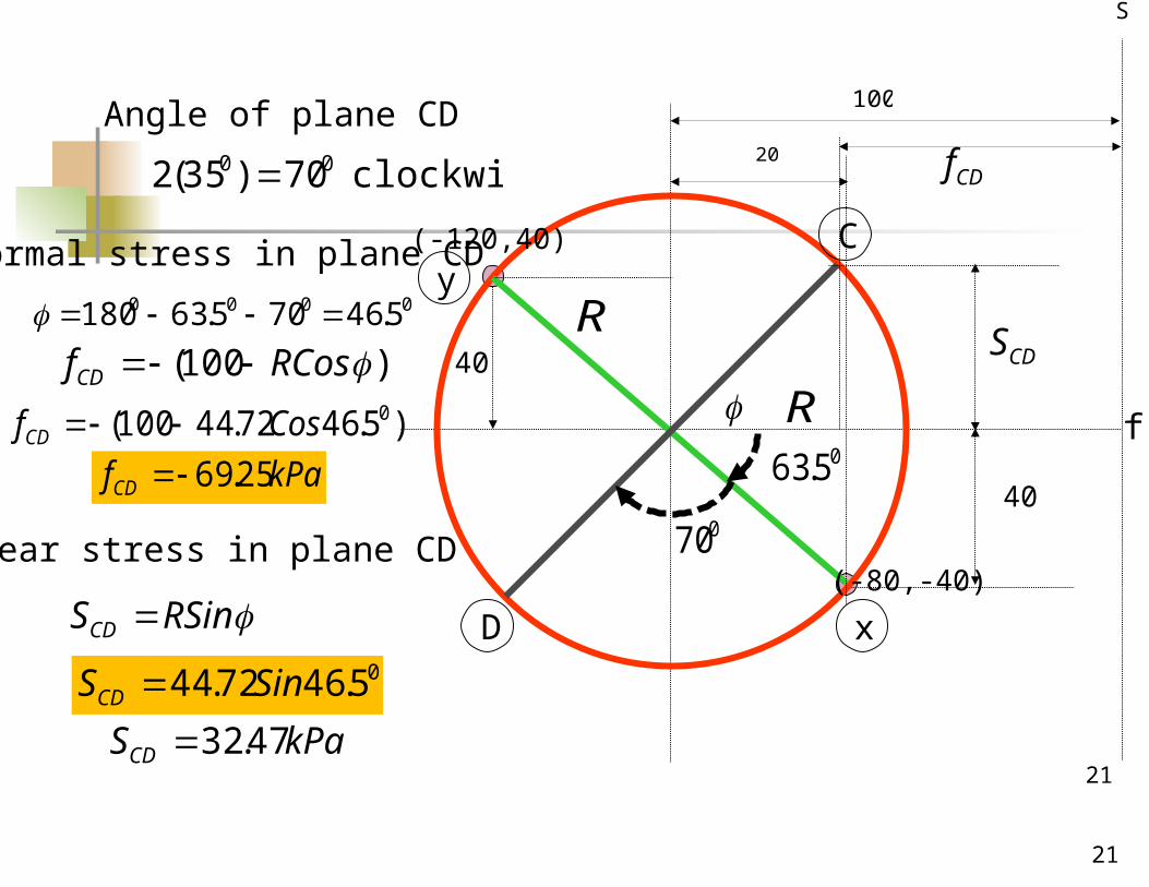
ProblemFor the soil element shown in figure, calculate the maximum and minimumPrincipal stress and the normal and shear stress on plane CD. 035
x
y
120 kPa
80 kPa
40 kPa
C
D
kPaSxy 40 kPa 40yxSGiven
kPaf x 80 kPaf y 120
)40,80( x )40,120(y
f
S
(-80,-40)
(-120,40)
(100,0)
y
x
1002
)80120(
202
)80120(
240
40
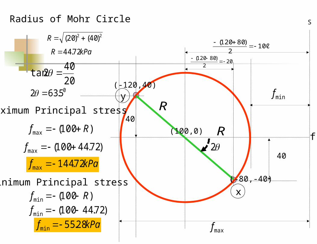
Radius of Mohr Circle
22 )40()20( R
kPaR 72.44
20
402tan
05.632
R
RMaximum Principal stress
maxf
)100(max Rf
)72.44100(max f
kPaf 72.144max
Minimum Principal stress
minf
)100(min Rf )72.44100(min f
kPaf 28.55min
21
21
f
S
(-80,-40)
(-120,40)y
x
100
20
05.6340
40
R
R
clockwise 70)35(2 00
Angle of plane CD
070
C
D
Normal stress in plane CD
CDf
)100( RCosfCD
0000 5.46705.63180
)5.4672.44100( 0CosfCD kPafCD 25.69
Shear stress in plane CD
CDS
RSinSCD 05.4672.44 SinSCD
kPaSCD 47.32
22
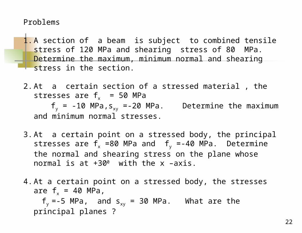
Problems
1. A section of a beam is subject to combined tensile stress of 120 MPa and shearing stress of 80 MPa. Determine the maximum, minimum normal and shearing stress in the section.
2. At a certain section of a stressed material , the stresses are fx = 50 MPa
fy = -10 MPa,sxy =-20 MPa. Determine the maximum and minimum normal stresses.
3. At a certain point on a stressed body, the principal stresses are fx =80 MPa and fy =-40 MPa. Determine the normal and shearing stress on the plane whose normal is at +300 with the x –axis.
4. At a certain point on a stressed body, the stresses are fx = 40 MPa,
fy =-5 MPa, and sxy = 30 MPa. What are the principal planes ?


