STEWART-BUCHANAN GAUGES LTD. Sales Office & Manufacturing Facility. Burnside Industrial Estate, Kilsyth. Glasgow, G65 9JX . SCOTLANDTel: +44 (0)1236 821533 Fax: +44 (0)1236 824090 E-Mail: [email protected] Web: stewarts-group.com
SAFETY, QUALITY, RELIABILITY.
Mechanical Pressure Measurement
Page 1 of 2
MODELS-631, 632, 633, 634All Stainless Steel Pressure Gauges
600 series gauges are suitable for corrosive environments in chemical, petro-chemical, refining, power, marine, food and pharmaceutical processing applications.
SPECIFICATIONS
CaseAISI 304 Stainless SteelBezel Polished Stainless Steel (Bayonet type)Weatherproof Construction to IP66 Ingress Protection rating
Socket + ElementAISI 316 Stainless Steel
Pressure Connection Thread⅛”, ¼”, ⅜”, ½” NPT, BSP, BSPT
Blowout ProtectionTop Mounted Rubber Disk
Movement Stainless Steel
DialWhite Aluminium (Black Printing)
PointerBlack Aluminium WindowSheet Glass
Standard Size63, 100, 150mm (2.½”, 4”, 6”)
Accuracy class63, 100 & 150mm ± 1% of span
Scale RangeVacuum to 1,400 bar (20,000 psi) (63mm gauge)Vacuum to 2,500 bar (36,000 psi) (100 & 150mm gauges
Optional ExtrasAISI 316 Stainless Steel caseWhite Plastic Dial (Black Printing)Mico adjustable pointer /Black finishMonel to Nace Mr-01-75 wetted partsOther pressure connections (Including high pressure)Laminated safety glass / Perspex windowCutomer logoLiquid fil l ingVibragauge®Snubbagauge®Further options on request
Stewart-Buchanan Gauges Ltd
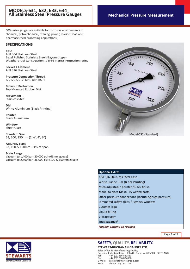
Model-632 (Standard)

Surface MountedModel - 631
Direct Mounted (Standard)Model - 632
Flush Mounted Clamp FixingModel - 634
Flush Mounted Screw FixingModel - 633
Mechanical Pressure MeasurementMODELS-631, 632, 633, 634All Stainless Steel Pressure Gauges
Page 2 of 2
How to order pressure gauges: State the following.
Pressure gauge model Nominal size Scale Range Size of connection Pressure Medium Optional extras required
WARNING: Misuse or misapplication of these products is potentially dangerous and could lead to personal injury.Do not use without first reading and understanding the Installation and Operation Instructions contained within our Guidance on use of Equipment booklet.If in doubt consult Stewarts.Specifications and dimensions given in this leaflet represent the state of engineering at the time of printing.Engineering modifications may take place without prior notice.
Diameter A B C D E F G H I J K L M N O Panel Cutout2.5" ( 63mm) 39 78.5 12.5 31 42 9.5 68.5 21.5 18 10 62 85 75 3.5 3.8 664" (100mm) 50.5 121 17 48.5 67 15 112 24.5 32 18 99 132 118 6 6 1066" (150mm) 50.5 174 17 48.5 93 15 162 24.5 32 18 148 185 168 5.8 5.8 153
Dim mm


![Aalco Metals Ltd Stainless Steel Pressure Ratings [131][1]](https://cdn.vdocuments.us/doc/165x107/563db9bf550346aa9a9f891d/aalco-metals-ltd-stainless-steel-pressure-ratings-1311.jpg)
