
Mobile and Sensor Systems
Lecture 2: Mobile Medium Access Control Protocols and Wireless Systems
Prof Cecilia Mascolo

In this lecture
• We will describe medium access control protocols and wireless systems (wifi networks, personal area networks, cellular networks)
2

Wireless Link Characteristics
Differences from wired networks:– decreased signal strength: radio signal attenuates
as it propagates through matter (path loss).– interference from other sources: standardized
wireless network frequencies (e.g., 2.4 GHz) shared by other devices (e.g., phone); devices (motors) interfere as well.
– multipath propagation: radio signal reflects off objects ground, arriving ad destination at slightly different times.
These characteristics make communication across (even a point to point) wireless link much more “difficult” .
3

Wireless Medium as Shared Medium
• The access to the wireless needs to be shared among the various transmitters.
• How?– Multiplexing the medium:
• Time (fixed or dynamic)• Space
• Frequency • Code
4

Multiplexing based Sharing• FDMA (Frequency Division Multiple Access):
– assign a certain frequency to a transmission channel between a sender and a receiver.
– permanent (e.g., radio broadcast), slow hopping (e.g., GSM), fast hopping (FHSS, Frequency Hopping Spread Spectrum).
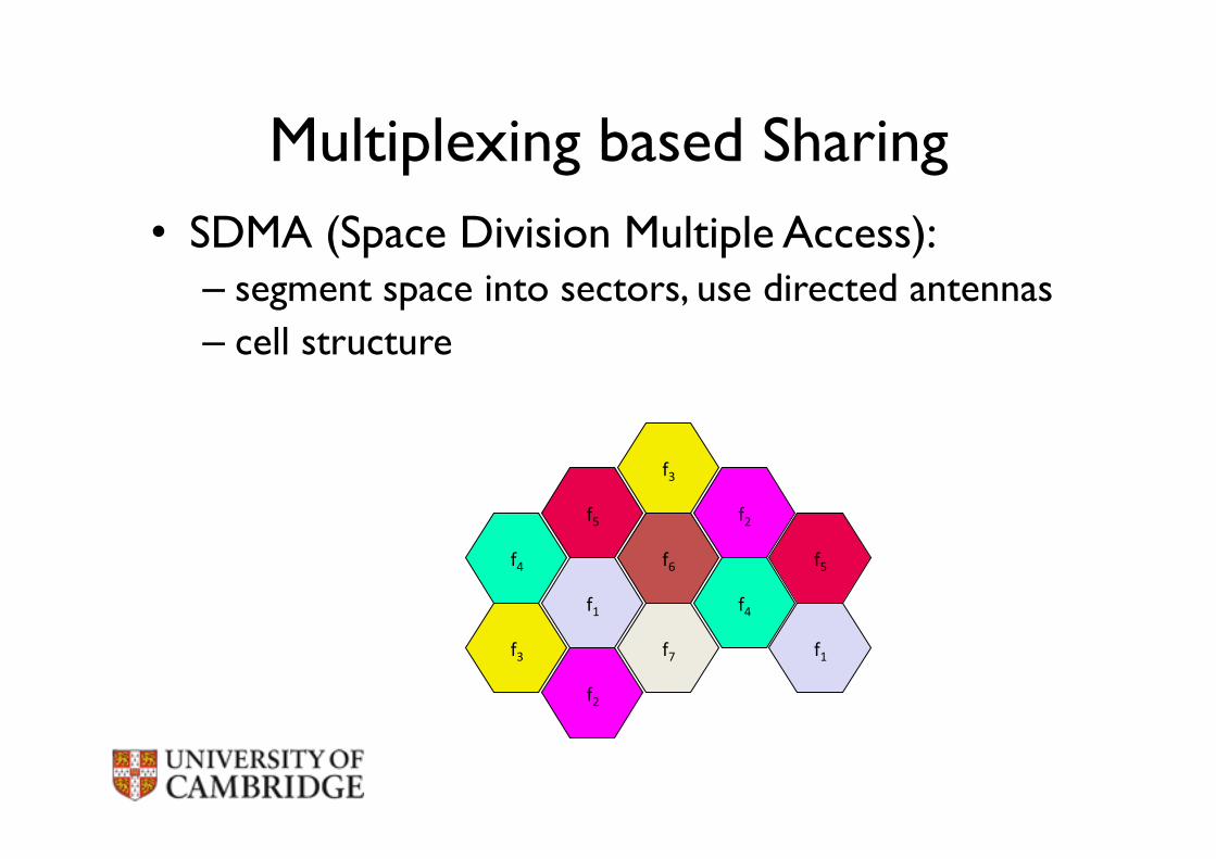
Multiplexing based Sharing• SDMA (Space Division Multiple Access):
– segment space into sectors, use directed antennas – cell structure
f4
f5
f1
f3
f2
f6
f7
f3
f2
f4
f5
f1

Multiplexing based Sharing
• TDMA (Time Division Multiple Access):– assign the fixed sending frequency to a transmission
channel between a sender and a receiver for a certain amount of time.
7
1 2 3 11 12 1 2 3 11 12
t downlink uplink
417 µs

Multiplexing based Sharing
• CDMA (Code Division Multiple Access)– Assign a code to each sender so that all of a
sender’s transmissions is on a unique “dimension”
8
k2 k3 k4 k5 k6 k1
f
t
c

• Multiplexing is one way to share the medium through the definition of “channels”.
• Once channels are established, packets will be sent through that:
– Might be a bit rigid as a method; for example, frequency division multiplexing would have issues with large numbers of users.
– Also depending on traffic and time some users might want to send more or less;
• More ad hoc approaches exist which allow channels to be shared in a “statistical” way.
Limitations of multiplexing
Review: Ethernet Medium ���Access Control (MAC)
• In Ethernet based fixed networks where you have wires between computers:
• CS (Carrier Sense): listen for others’ transmissions before transmitting; defer to others you hear.
• CD (Collision Detection): as you transmit, listen and verify you hear exactly what you send; if not, back off random interval, within exponentially longer range each time you transmit unsuccessfully.
Can CD be applied on wireless networks?

Can we apply the same MAC protocols in wireless?
• Problems in wireless networks:– signal strength decreases proportionally to
the square of the distance;– the sender would apply CS and CD, but
collisions happen at the receiver;
– it might be the case that a sender cannot “hear” the collision, i.e., CD does not work;
– furthermore, CS might not work if, e.g., a terminal is “hidden”.

CSMA/CA: Carrier Sensing Multiple Access Protocol with Collision Avoidance
19
CS/ECE 438 © Robin Kravets, UIUC - Spring 2007 37
Interframe Spacing
! Interframe spacing " Plays a large role in coordinating access to the
transmission medium
! Varying interframe spacings" Creates different priority levels for different types of traffic!
! 802.11 uses 4 different interframe spacings
t
medium busySIFS
PIFS
DIFSDIFS
next framecontention
direct access if
medium is free ! DIFS
CS/ECE 438 © Robin Kravets, UIUC - Spring 2007 38
IEEE 802.11 - CSMA/CA
! Sensing the medium
! If free for an Inter-Frame Space (IFS)" Station can start sending (IFS depends on service type)
! If busy" Station waits for a free IFS, then waits a random back-off time
(collision avoidance, multiple of slot-time)
! If another station transmits during back-off time " The back-off timer stops (fairness)
t
medium busy
DIFSDIFS
next frame
contention window
(randomized back-off
mechanism)
slot timedirect access if
medium is free ! DIFS
CSMA/CA: sense medium. If free transmit (although this might generate collision at the receiver). If not, wait with a back off strategy. Transmit when medium is sensed free.

• Hidden terminals:– A sends to B, C cannot receive from A. – C wants to send to B, C senses a “free”
medium (CS fails).– Collision at B, A cannot receive the collision
(CD fails).– A is “hidden” for C.
Hidden Terminal
B A C
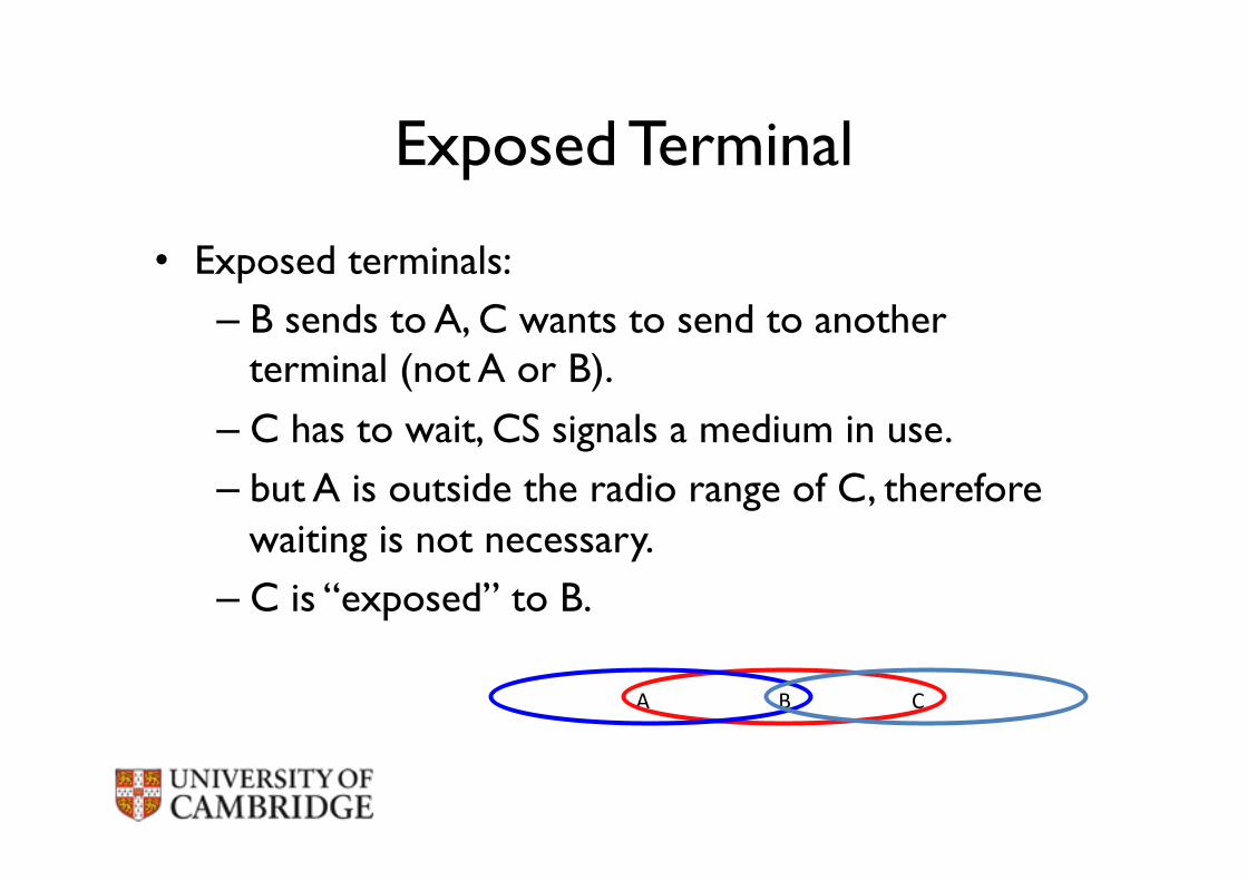
Exposed Terminal
• Exposed terminals:– B sends to A, C wants to send to another
terminal (not A or B).
– C has to wait, CS signals a medium in use.– but A is outside the radio range of C, therefore
waiting is not necessary.– C is “exposed” to B.
B A C

Multiple Access with Collision Avoidance ���(for Wireless): MACA(W))
• Sender B asks receiver C whether C is able to receive a transmission���Request to Send (RTS).
• Receiver C agrees, sends out a Clear to Send (CTS).
• Potential interferers overhear either RTS or CTS and know about impending transmission and for how long it will last.
– Store this information in a Network Allocation Vector.
• B sends, C acks: ! MACA(W) protocol (used e.g. in
IEEE 802.11).
A B C D
RTS
CTS
Data
Ack
NAV indicates busy medium
NAV indicates busy medium

MACA(W)
• Absent CTS, sender backs off exponentially before retrying.
• RTS and CTS can still themselves collide at their receivers; less chance as they’re short.
• What’s the effect on exposed terminal problem?

RTS/CTS • RTS/CTS ameliorate, but do not solve hidden/exposed terminal problems.• Example problem cases:
A B C D
RTS
CTS
Data
A B C D
RTS
RTS
CTS
RTS
RTSCTS
CTSData
Data
Ack

The 802.11 Protocol• 802.11 uses 2 modes of operation: a basic CSMA/CA
(in base station mode) and the RTS/CTS mode.
• Generally 802.11 drivers leave the RTS/CTS off by default.
• Also tests in practice show that hidden terminal might not be a problem in most cases as interference range is more than double communication range. Consider A->B<-C when A transmits it is very likely C can sense A’s carrier directly.

IEEE 802.11 Wireless LAN• 802.11b
– 2.4-5 GHz unlicensed spectrum
– up to 11 Mbps
• 802.11a – 5-6 GHz range
– up to 54 Mbps
• 802.11g – 2.4-5 GHz range
– up to 54 Mbps
• 802.11n: multiple antennae
– 2.4-5 GHz range– up to 200 Mbps
All have base-‐staAon and ad-‐hoc network versions
19

802.11 LAN Architecture
• wireless host communicates with base staAon • base staAon = access point
(AP) • Basic Service Set (BSS) (aka
“cell”) in infrastructure mode contains: • wireless hosts • access point (AP): base
staAon • ad hoc mode: hosts only
BSS 1
BSS 2
Internet
hub, switch or router AP
AP
20

802.11: Channels, Association
• 802.11b: 2.4GHz-2.485GHz spectrum divided into 11 channels at different frequencies:– AP admin chooses frequency for AP.– interference possible: channel can be same as that
chosen by neighboring AP!• host: must associate with an AP:
– scans channels, listening for beacon frames containing AP’s name (SSID) and MAC address.
– selects AP to associate with.– may perform authentication.– will typically run DHCP to get IP address in AP’s
subnet.
21
M radius of coverage
S
SS
P
P
P
P
M
S
Master device
Slave device
Parked device (inactive) P
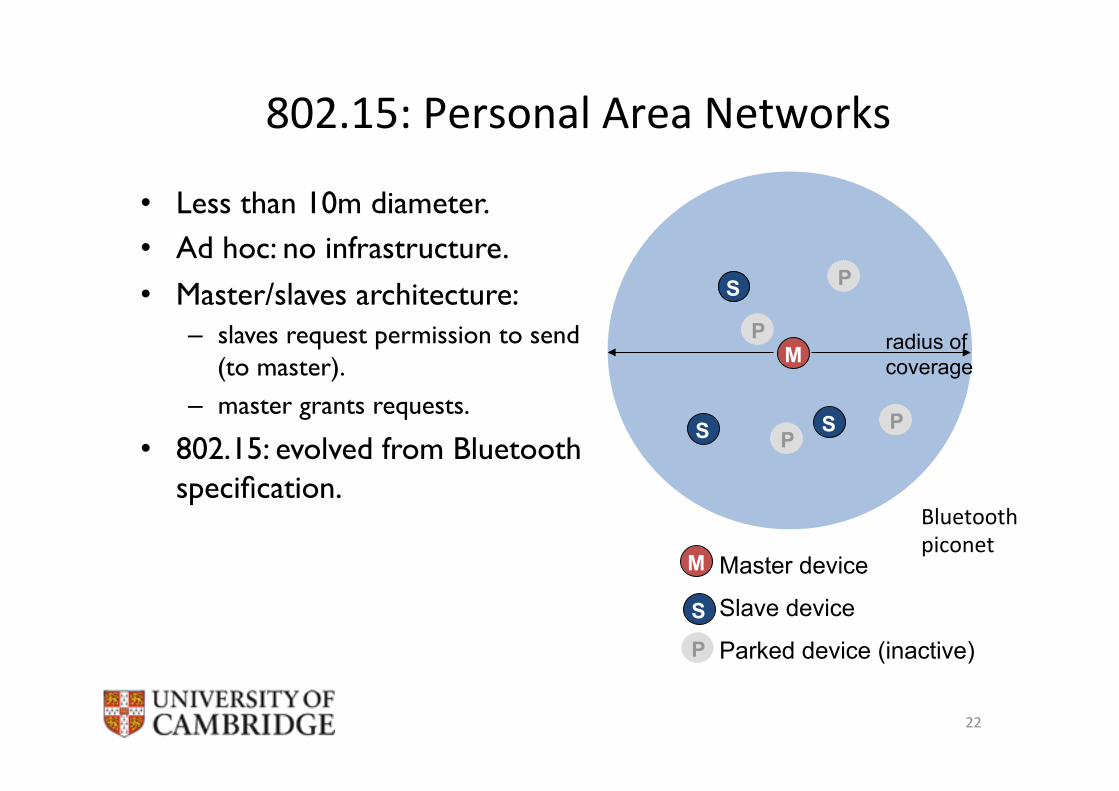
802.15: Personal Area Networks
• Less than 10m diameter.• Ad hoc: no infrastructure.
• Master/slaves architecture:– slaves request permission to send
(to master).– master grants requests.
• 802.15: evolved from Bluetooth specification.
22
Bluetooth piconet

Bluetooth and Zigbee
• Two main short-range technologies:– Bluetooth (802.15.1)– Zigbee (802.15.4)
• Bluetooth provides a “cable replacement” data rate of over a Megabit per second.
• Zigbee is targeted at lower-powered, lower-data-rate, lower-duty-cycle applications:– Environmental sensors– Security devices– Wall-mounted devices– …
23

Mobile Switching Center
Public telephonenetwork, andInternet
Mobile Switching Center
Components of cellular network architecture
v connects cells to wide area netv manages call setup (more later!)v handles mobility (more later!)
MSC
v covers geographical regionv base station (BS) analogous to 802.11 APv mobile users attach to network through BSv air-interface: physical and link layer protocol between mobile and BS
cell
wired network
24

Cellular standards: brief survey
2G systems: voice channels• IS-136 TDMA: combined FDMA/TDMA (North America)• GSM (global system for mobile communications): combined
FDMA/TDMA – most widely deployed
• IS-95 CDMA: code division multiple access
IS-136 GSM IS-95 GPRS EDGE CDMA-2000
UMTS
TDMA/FDMA Don’t drown in a bowlof alphabet soup: use thisfor reference only
25

Cellular standards: brief survey
2.5 G systems: voice and data channelsie extends 2G for Internet usage without touching the core.
• 2G extensions – general packet radio service (GPRS)
• evolved from GSM • IP datagrams carrying FDM/TDM channels are forwarded to a Serving GPRS Support
Node (SGSN) instead of the MSC and then on to the Internet
– enhanced data rates for global evolution (EDGE)• also evolved from GSM, using enhanced modulation • data rates up to 384K
26

Cellular standards: brief survey
3G systems: voice/data• Universal Mobile Telecommunications Service
(UMTS)
– It uses CDMA on TDMA slots available on multiple frequencies.
• data service: High Speed Uplink/Downlink packet Access (HSDPA/HSUPA) up to 14 Mbps
27

Handling mobility in cellular networks
• home network: network of cellular provider you subscribe to (e.g.,Vodafone, O2, etc.)– home location register (HLR): database in home
network containing permanent cell phone #, profile information (services, preferences, billing), information about current location (could be in another network)
• visited network: network in which mobile currently resides– visitor location register (VLR): database with entry
for each user currently in network
28

Public switched telephonenetwork
mobileuser
homeMobile
Switching Center
HLR home network
visitednetwork
correspondent
Mobile Switching Center
VLR
GSM: Indirect Routing to Mobile
1 call routed to home network
2
home MSC consults HLR,gets roaming number ofmobile in visited network
3
home MSC sets up 2nd leg of callto MSC in visited network
4
MSC in visited network completescall through base station to mobile
29

3G Networks
• 3G core network connects radio access networks to the public Internet.
• Given the considerable amount of existing infrastructure, the approach taken by the designers of 3G data services was to leave the existing core GSM cellular network untouched.
• Cellular data functionality was added in parallel to the existing cellular network.
30

LTE-4G Networks
• Currently being deployed around the world.• Main differences with 3G are in the network
core (“all-IP network” for voice and data) and radio access.
• The maximum data rate for LTE (long-term evolution) is 100 Mbps in the downstream direction and 50 Mbps in the upstream direction, when using 20 MHz worth of wireless spectrum.
31
WiMAX
• An additional 4G wireless technology is WiMAX (which stands for World Interoperability for Microwave Access).
• LTE has significant more momentum.
32
Wireless, mobility: impact on higher layer protocols
• Logically, impact should be minimal:– best effort service model remains unchanged.
– TCP and UDP can (and do) run over wireless, mobile.• but performance-wise:
– packet loss/delay due to bit-errors (discarded packets, delays for link-layer retransmissions), and handoff.
– TCP interprets loss as congestion, will decrease congestion window un-necessarily.
– delay impairments for real-time traffic.– limited bandwidth of wireless links.
33

Reference
• Chapter 6 of James F. Kurose and Keith W. Ross. Computer Networking. A Top Down Approach 6th Edition Pearson 2012.
• Schiller, J. (2003). Mobile communications. Pearson (2nd ed.).
34


