
MMooddbbuuss IInntteeggrraattiioonn GGuuiiddee
ffoorr ii--VVuu®® XXTT oorr TTrruuVVuu™™ ccoonnttrroolllleerrss
CARRIER CORPORATION ©2020 · Catalog No. 11-808-695-01 · 4/7/2020

Verify that you have the most current version of this document from www.hvacpartners.com or www.accounts.ivusystems.com or your local Carrier office.
Important changes are listed in Document revision history at the end of this document.
CARRIER CORPORATION ©2020. All rights reserved throughout the world. i-Vu is a registered trademark of Carrier Corporation. All other trademarks are the property of their respective owners.

Contents Overview ............................................................................................................................................................... 1
Controller as a master device on EIA-485 ........................................................................................................... 2 Before-you-begin checklist .................................................................................................................................. 2 The integration process ....................................................................................................................................... 3 1 Create a control program in the Snap application ...................................................................................... 3
Formatting a Modbus address ........................................................................................................ 3 Editing a microblock address .......................................................................................................... 6
2 Download the driver and control programs ................................................................................................. 6 3 Connect the Carrier controller to the third-party device ............................................................................. 8
Wiring specifications ....................................................................................................................... 8 To wire a third-party device ............................................................................................................. 8
4 Set up the driver properties ............................................................................................................................ 9 5 Verify the Carrier controller is set up correctly ......................................................................................... 10
To capture communication using PuTTY ....................................................................................... 11
Controller as a slave device on EIA-485 ............................................................................................................. 13 Before-you-begin checklist ............................................................................................................................... 13 The integration process .................................................................................................................................... 14 1 Create a control program in the Snap application ................................................................................... 14
Formatting a Modbus address ...................................................................................................... 14 Editing a microblock address ........................................................................................................ 16
2 Download the driver and control programs .............................................................................................. 16 3 Connect the Carrier controller to the third-party device .......................................................................... 18
Wiring specifications ..................................................................................................................... 18 To wire a third-party device ........................................................................................................... 18
4 Set up the driver properties ......................................................................................................................... 19 5 Verify the controller is set up correctly....................................................................................................... 20
To capture communication using PuTTY ....................................................................................... 21
Controller as a client device on Ethernet ........................................................................................................... 24 Before-you-begin checklist ............................................................................................................................... 24 The integration process .................................................................................................................................... 25 1 Create a control program in the Snap application ................................................................................... 25
Formatting a Modbus address ...................................................................................................... 25 Editing a microblock address ........................................................................................................ 28
2 Download the driver and control programs .............................................................................................. 28 3 Connect the Carrier controller to the third-party device .......................................................................... 30 4 Set up the driver properties ......................................................................................................................... 30 5 Verify the controller is set up correctly....................................................................................................... 31
To capture communication using Wireshark ................................................................................. 32 To capture communication using PuTTY ....................................................................................... 33
Controller as a server device on Ethernet .......................................................................................................... 35 Before-you-begin checklist ............................................................................................................................... 35 The integration process .................................................................................................................................... 35 1 Create a control program in the Snap application ................................................................................... 36
Formatting a Modbus address ...................................................................................................... 36 Editing a microblock address ........................................................................................................ 37
2 Download the driver and control programs .............................................................................................. 38 3 Connect the Carrier controller to the third-party device .......................................................................... 39 4 Set up the driver properties ......................................................................................................................... 40 5 Verify the controller is set up correctly....................................................................................................... 40
To capture communication using Wireshark ................................................................................. 41 To capture communication using PuTTY ....................................................................................... 42

Contents
Modbus Troubleshooting .................................................................................................................................... 44 If the Carrier controller is a Serial Master or Ethernet Client ...................................................................... 44
Register addresses ....................................................................................................................... 44 Errors ............................................................................................................................................ 45
If the Carrier controller is a Serial Slave or Ethernet Server ....................................................................... 48 Register addresses ....................................................................................................................... 48 Errors ............................................................................................................................................ 49
Appendix A - Migrating a control program used with a previous Modbus driver ............................................... 50
Appendix B - Modbus Protocol Conformance Statement .................................................................................. 51
Appendix C - Configuring the driver parameters by using the Service Port ....................................................... 53
Appendix D - Recording the Telnet diagnostics session(s) in the controller’s system log files ......................... 55
Document revision history.................................................................................................................................. 56

Modbus Integration Guide CARRIER CORPORATION ©2020
for i-Vu® XT or TruVu™ controllers All rights reserved
1
You can use a Carrier i-Vu® XT or TruVu™ controller to integrate Modbus device(s) with your i-Vu® system. The controller can serve as a master or slave on a serial network, or a client or server on a TCP/IP network.
This document is divided into 4 sections that provide integration instructions for the 4 scenarios listed in the first two columns below. Determine how your Carrier controller will be used, then go to the appropriate page for the
instructions.
If the Carrier controller is to be a Modbus...
...on this media type...
...you can use this controller port...
See...
Master EIA-485, 2 wire
S1 or S2
Controller as a master device on EIA-485 (page 2)
Slave EIA-485, 2 wire
S1 or S2
Controller as a slave device on EIA-485 (page 13)
Client Ethernet Gig-E Controller as a client device on Ethernet (page 24)
Server Ethernet Gig-E Controller as a server device on Ethernet (page 35)
NOTES
All i-Vu® XT or TruVu™ controllers, except the non-routing controllers, can have Modbus devices connected to ports S1, S2, and Gig-E simultaneously. The third-party point count for the controller equals the total of the 3
ports. A non-routing controller can have only one port configured for Modbus.
If multiple ports are used for Modbus, the ports can have different functionality. For example, Port S1 could be a serial master or slave, Port S2 could be a serial slave, and the Gig-E port could be an Ethernet client or
server.
CAUTION If you want to upgrade a system from an older Modbus application, carefully review Appendix A -
Migrating a control program used with a previous Modbus driver (page 50).
Overview

Controller as a master device on EIA-485
Modbus Integration Guide CARRIER CORPORATION ©2020
for i-Vu® XT or TruVu™ controllers All rights reserved
2
NOTE Modbus supports a single master on each network.
Carrier
Controller i-Vu® XT BACnet Link (part #XT-LB)
TruVuTM MPC Processor
(part #s TV-MPCXP,TV-MPCXP1628, TV-MPCXP1628-NR )
Driver drv_fwex_<latest version>.driverx
Read/write capability Can read from and write to the third-party equipment
Third party
Supported equipment Any slave device that supports the Modbus (Modicon) protocol
Network media type EIA-485
Quantity of Modbus slave devices you can physically connect to Port S1 or Port S2 on
the Carrier master controller
For EIA-485: Up to 254 Modbus slaves
NOTE You may reach the point limitation of the Carrier controller before connecting 254 Modbus
slaves.
Before-you-begin checklist
You need the following items, information, and skills for the integration process:
A points list for each Modbus device that includes register addresses and read/write capabilities. Points lists are usually available from the third-party manufacturer’s representative or website.
Modbus device addresses
A port pinout/configuration of the Modbus device. Pinouts are usually available from the third-party manufacturer’s representative or website.
The Modbus network’s transmission mode, baud rate, data bits, parity, and stop bits
Verification that all communication properties have been set on the Modbus devices
Verification of communications through the port the Carrier controller will connect to
Experience creating control programs in the Snap application
Experience installing, wiring, setting up, and downloading to the Carrier controller
Controller as a master device on EIA-485

Controller as a master device on EIA-485
Modbus Integration Guide CARRIER CORPORATION ©2020
for i-Vu® XT or TruVu™ controllers All rights reserved
3
The integration process
Follow the steps in this section to integrate one or more third-party Modbus devices into a i-Vu® system using the Carrier controller. To install and network the Carrier controller, see the controller's Installation and Start-up Guide.
1 Create a control program in the Snap application
When you create your control program, use a Network I/O microblock for each third-party point.
TIP Verify the third-party manufacturer’s register addressing pattern by establishing communication with a few points whose values you can physically manipulate before you spend time addressing the remaining
integration points.
Formatting a Modbus address
Use the information below to format a valid address in each microblock that you use to read or write to a third-party point.
CAUTION When integrating third-party devices into a i-Vu® system, most communication problems are caused by incorrect
data or typing errors in the microblock's Address field.
Example: modbus2://UINT/400128/26
NOTE To send a broadcast to all Modbus devices on the port specified by the protocol signature, use 0 for the device address in a network output microblock.
Protocol
If the point is in a Modbus device connected to the Carrier controller's port...
Use the following protocol signature *
S1 modbus1://
S2 modbus2://
* You can also use modbus:// for points on one of the ports, but not both ports.

Controller as a master device on EIA-485
Modbus Integration Guide CARRIER CORPORATION ©2020
for i-Vu® XT or TruVu™ controllers All rights reserved
4
Dynamic Modbus Address
There is a special “wildcard” mode that allows the address of the Modbus slave to be deferred at runtime to a value determined by the control program. A wire value in the control program can set the slave address of many network point microblocks in the same control program. Dynamic addressing allows a control program to
dynamically browse from one Modbus slave device to another by changing one value in the control program that sets the Modbus slave address for all of the points that are configured to use the “wildcard” slave address.
There must be one ANO microblock within the control program configured so that its Address field is set to “modbus://myaddress” (or “modbus1://myaddress” or “modbus2://myaddress”, as appropriate). The control
program wire value feeding the input nib of this ANO microblock will determine the Modbus slave address of all microblocks set to the wildcard address that have a matching Protocol field.
To configure a network point to the wildcard address, place an * (asterisk) where the numeric slave address would normally be in the Address field.
Example: modbus://UINT/400128/*
When running, this asterisk will be replaced with a numeric slave address as determined by the wire input nib of the specially designated ANO microblock, the “myaddress” microblock. Changing the value of this ANO microblock
will dynamically change the slave address of all the network point microblocks configured with the wildcard address, which allows one control program to browse from one Modbus slave to another by changing this one ANO
value.
Register type/Register address
To... this kind of value...
use this microblock...
with this register type...
and a Modbus register address in
this range... 1
Read 0 to 65,535 Unsigned 16-bit integer Input register (3XXXXX)
ANI Uint (not Unit) 300001–365535
0 to 65,535 Unsigned 16-bit integer
Holding register (4XXXXX)
ANI Uint (not Unit) 400001–465535
0 to 4,294,967,296 Unsigned, 32-bit (long) integer
Input register (3XXXXX)
ANI Uint32 300001–365535
0 to 4,294,967,296 Unsigned, 32-bit (long) integer Holding register (4XXXXX)
ANI Uint32 400001–465535
–32,768 to +32,767 Signed 16-bit integer
Input register (3XXXXX)
ANI Sint 300001–365535
–32,768 to +32,767 Signed 16-bit integer
Holding register (4XXXXX)
ANI Sint 400001–465535
-2,147,483,648 to 2,147,483,647 Signed, 32-bit (long) integer Input register (3XXXXX)
ANI Sint32 300001–365535

Controller as a master device on EIA-485
Modbus Integration Guide CARRIER CORPORATION ©2020
for i-Vu® XT or TruVu™ controllers All rights reserved
5
To... this kind of value...
use this microblock...
with this register type...
and a Modbus register address in
this range... 1
-2,147,483,648 to 2,147,483,647 Signed, 32-bit (long) integer
Holding register (4XXXXX)
ANI Sint32 400001–465535
Value with decimal point Input register (3XXXXX)
ANI Float 300001–365535 2
Value with decimal point Holding register (4XXXXX)
ANI Float 400001–465535 2
0 or 1 Coil / Discrete (binary) output
BNI (or ANI)
Do 1–65535 3
0 or 1 Discrete (binary) input (1XXXXX)
BNI (or ANI)
Di 100001–165535
0 or 1 Input register (3XXXXX)
BNI BITn (where n is a value 0-15 defined in points list)
300001–365535
0 or 1 Holding register (4XXXXX)
BNI BITn (where n is a value 0-15 defined in
points list)
400001–465535
To... this kind of value...
use this microblock...
with this register type...
and a Modbus register address in
this range... 1
Write 0 to 65,535 Unsigned 16-bit integer
Holding register (4XXXXX)
ANO Uint (not Unit) 400001–465535
–32,768 to +32,767 Signed 16-bit integer
Holding register (4XXXXX)
ANO Sint 400001–465535
Value with decimal point Holding register (4XXXXX)
ANO Float 400001–465535 2
0 or 1 Coil Discrete (binary) output
BNO (or ANO)
Do 1–65535 3
0 or 1 Holding register (4XXXXX)
BNO (or ANO)
BITn (where n is a value 0-15 defined in points list)
400001–465535

Controller as a master device on EIA-485
Modbus Integration Guide CARRIER CORPORATION ©2020
for i-Vu® XT or TruVu™ controllers All rights reserved
6
1 The Modbus register address (sometimes called register, address, code, or parameter) must be a decimal
value. If the register addresses in the points list include the letters A-F, use a scientific calculator to convert
these hexadecimal values to decimal values.
If the register addresses in the points list are 5-digit numbers in the range #0001-#9999 (where # = the prefix
1, 3, or 4), you may use the addresses as they are, or change them to fit the formats in the table above by shifting the prefix one digit to the left. For example, if you see the address 38129, you can also use 308129.
2 Each Float uses 2 consecutive Modbus register addresses. Use the lower number in the microblock address.
3 Enter the number without any leading zeros. For example, enter 125, not 000125.
64-bit Modbus registers are not supported. See Modbus Troubleshooting (page 44) for more information on register addresses.
Editing a microblock address
You can edit a microblock address in the following places:
In the Snap Property Editor
In the i-Vu® interface, on the microblock's Properties page > Details tab
In the i-Vu® interface, on the control program's Properties page > Network Points tab
2 Download the driver and control programs
In the i-Vu® XT or TruVu™ controller, Modbus communication is already in the standard drv_fwex driver <v103 or later>. You do not need a special Modbus driver.
If you need an updated driver or the latest SAL library, go to Carrier Control Systems Support Site http://www.hvacpartners.com/, https://accounts.ivusystems.com/ and save it to your computer.
To change the driver in the controller
1 Do one of the following:
If the driver is...
In the Driver Version drop-down list a. Select the driver.
b. Click Accept.
Not in the Driver Version drop-down list a. Click Add.
b. Browse to select the driver.
c. Click Open.
d. Click Continue.
e. Click Close.
f. Click Close again.
2 Click the Download All Content button.
3 Click OK.
4 Click Accept.
Controller as a master device on EIA-485
Modbus Integration Guide CARRIER CORPORATION ©2020
for i-Vu® XT or TruVu™ controllers All rights reserved
7
To update the SAL library in the i-Vu® application
1 In the i-Vu® interface, click System Menu , then select System Options > Update.
NOTE Expand Current Libraries (.sal) to see the current SAL libraries and their revision. Compare them to what you downloaded and determine if any of them need updating.
2 Click and browse to the updated .sal file that you have saved on your computer, select the file, and click Open.
3 Click Continue.
4 When process is complete, the message appears File added successfully.
5 Click Close.
6 Click Close again.
7 Click the Download All Content button.
8 Click OK.
9 Click Accept.
To add a control program
NOTE i-Vu® Pro - Place the .equipment file in i-Vu_Pro_x.x\webroot\<system_name>\programs.
1 In the i-Vu® interface, select the router in the navigation tree and go to the Devices > Manage tab.
2 Select the controller in the list on the page.
3 If you are adding a new control program, click the Add Control Program button . A dialog
window appears.
4 Enter a name for your control program in Display Name and select your controller in the Controller drop-down
list.
5 Do one of the following:
If the control program is...
In the Control Program drop-down list Select the control program.
Not in the Control Program drop-down list a. Click Add New.
b. Browse to select the control program.
c. Click Open.
d. Click Continue.
e. Click Close.
6 Click Continue. When message appears File added successfully, click Close.
7 Click Close again.
8 Right-click on the controller in the list and select Check Status from the list. The status of the controller
should say File Mismatch.
9 Click the Download All Content button.
Controller as a master device on EIA-485
Modbus Integration Guide CARRIER CORPORATION ©2020
for i-Vu® XT or TruVu™ controllers All rights reserved
8
3 Connect the Carrier controller to the third-party device
Wiring specifications
For... Use...
EIA-485 24 AWG twisted, shielded pair cable for up to 200 feet (60.96 meters) 2
or
22 AWG twisted, shielded pair cable for up to 2000 feet (609.6 meters)
See the Open Controller Wiring Guide for details.
To wire a third-party device
1 Turn off the Carrier controller's power.
2 Check the communications wiring for shorts and grounds.
3 Set switches on the Carrier controller. See table below.
4 Wire the Carrier controller to the third-party device. See table and notes below.
5 Turn on the Carrier controller's power.
For...
Use Carrier controller port...
Wire Carrier terminal...
...to third-party device terminal
Set switches on Carrier controller
EIA-485, 2-wire
S1 Net+
Net-
+
-
1 Set the rotary protocol selector switch to 3 (Modbus).
NOTE The rotary address switches are not used for Modbus in Master Mode.
2 If this controller is on the end of the EIA-
485 network segment, set the Port S1 End
of Net? switch to YES. If not, set to NO.
3 Set master mode, baud rate, and other
relevant Modbus parameters in the driver properties, as detailed in the next section.
EIA-485, 2-wire
S2 Net+
Net-
+
-
1 If this controller is on the end of the EIA-
485 network segment, set the Port S1 End
of Net? switch to YES. If not, set to NO.
2 To enable and configure Modbus on Port S2, set the parameters in the driver
properties, as detailed in the next section.
CAUTION If Port S2 is enabled for BACnet
and Port S2 is also set to be the Home Network, you cannot enable Modbus on Port
S2.
Controller as a master device on EIA-485
Modbus Integration Guide CARRIER CORPORATION ©2020
for i-Vu® XT or TruVu™ controllers All rights reserved
9
NOTES
If you cannot determine the media type or connections of the third-party device, contact your third-party representative.
Use the same polarity throughout the network segment.
Repeaters are required for more than 32 devices on an EIA-485 network. See your third-party device manufacturer's recommendations.
To reduce communication and data errors, terminate each end of an EIA-485 network with a resistor whose value equals the network's characteristic impedance. Carrier's controllers provide this terminating resistance
by setting the End of Net? switch to YES. Make sure that only devices at the end of a network have termination enabled.
A solid receive light on the Carrier controller indicates a wiring or polarity problem.
If more than one controller is using the same slave address on the same Modbus segment, you may see unexplained data errors in the control program. Each Modbus node on a Modbus serial network must be
assigned a unique node address.
When Port S1 or S2 is in master mode, autobaud is always disabled. You can only enable autobaud when
Port S1 or S2 is in slave mode.
4 Set up the driver properties
1 On the i-Vu® navigation tree, right-click the i-Vu® XT or TruVu™ controller and select Driver Properties.
2 Expand Communication Status, then select Modbus Serial.
3 Under Port Configuration, enable the port(s) on the controller that third-party device(s) are connected to.
4 For each port that you enabled, select one of the following in the Supported Microblock Signature field:
Select... If the Modbus point addresses on the port use...
modbus#:// Only this signature
modbus:// & modbus#:// Both types of signatures
5 Set the remaining fields under Port Configuration to match the third-party device.
6 Under Protocol Configuration, set This device is a to Master.
7 Set the remaining fields using information from the third-party manufacturer's representative. Select the
Details checkbox for help.
8 On the Driver Properties tree, select Communication Status.
9 In the Protocol Status table, verify the following for the port you enabled:
Modbus 1 shows Running on Port S1
Modbus 2 shows Running on Port S2
If the status shows Not Running or the wrong port, verify that:
○ You selected the correct port in step 3 above.
○ You set the controller's switches correctly.
○ The control program has at least one valid Modbus address. The driver must detect at least one valid address to initiate Modbus communications.

Controller as a master device on EIA-485
Modbus Integration Guide CARRIER CORPORATION ©2020
for i-Vu® XT or TruVu™ controllers All rights reserved
10
5 Verify the Carrier controller is set up correctly
1 On the i-Vu® navigation tree, select the control program for the Carrier controller.
2 Select the Properties page > Network Points tab.
If... Then...
You see the point value you expect with no errors in the Error
column
You have successfully established communication with the third-party device.
All points show question marks instead of values
The i-Vu® application is not communicating with the Carrier controller or the control program. Troubleshoot the controller's communications. See the
controller's Installation and Start-up Guide.
Some points show question marks instead of values
You may have exceeded the third-party points available in the controller. If so, do one of the following:
Use a controller that provides more third-party points.
Split the points between two control programs used in separate controllers.
To determine the number of third-party points used in a controller:
On the i-Vu® navigation tree, right-click on the controller and select Driver
Properties > Driver > Properties > Settings tab, and then scroll to Network Microblocks. Modbus integration points capacity shows how many points the
controller allows and integration points active shows how many are currently active.
The point name is red Select the control program on the i-Vu® navigation tree. Go to Properties > Network Points tab.
1 - Communications Disabled for this Microblock
Enable the microblock's Communications Enabled field on the Network Points tab, on the microblock's Properties page > Details tab, or in the
Snap application.
3 - Address Error - Unknown Protocol Specified Select the correct port on the Modbus driver page, verify that Address in
the microblock is correct, or set the switches correctly on the controller.
All other errors On the i-Vu® navigation tree, right-click the controller and select Driver Properties, then select Communication Status > Modbus Error
Definitions. Find the error and its possible solution.
A value is incorrect Verify that:
The Address in the microblock is correct.
The retrieved value is scaled properly, if necessary. For example, scaled
from Celsius to Fahrenheit. Refer to the third-party manufacturer's documentation or the controller's Installation and Start-up Guide for
scaling information.
If the above solutions do not resolve the problem, gather the following information for Technical Support:
A diagnostic capture. See next topic.
A screenshot of the Driver > Communication Status Properties page and the Driver > Communication
Status > Modbus Serial > Properties page

Controller as a master device on EIA-485
Modbus Integration Guide CARRIER CORPORATION ©2020
for i-Vu® XT or TruVu™ controllers All rights reserved
11
A screenshot of the Properties page > Network Points tab showing addresses and errors
Technical instructions for the third-party device, if available
To capture communication using PuTTY
Use PuTTY, a free open source terminal emulation program that works with all Windows operating systems, to capture communication between the controller and the Modbus device into a text file.
PREREQUISITES
Download and install PuTTY from the PuTTY website (http://www.chiark.greenend.org.uk/~sgtatham/putty/download.html).
Get the Carrier controller's IP address.
Get the longest microblock refresh time in the control program that has the error you are troubleshooting. In i-
Vu®, view the control program's Properties page > Network Points tab to see all the refresh times.
1 Connect your computer's Ethernet port to the controller's Gig-E port using one of the following:
A CAT5 or higher Ethernet crossover cable
A hub and a CAT5 or higher Ethernet straight-through cable
2 Ping the Carrier controller to verify communications between the controller and the computer you are using to
get this capture.
3 On the i-Vu® navigation tree, right-click the controller, select Driver Properties, and then select Communication Status.
4 On the Properties tab, check Enable Telnet diagnostics, and then click Apply.
5 Start PuTTY.
6 Enter the controller's IP address.
7 Select Telnet as the Connection Type.
8 Click the Logging option in the upper left corner of the left pane.
9 Select Printable output.
10 Select a location for the capture text file.
11 Click Open to start the session.
12 After Login:>, type: diagport
Press Enter.
13 To capture data receipts, after diagport>, do one of the following:
For Modbus on Port S1, type: modbus1 rx
For Modbus on Port S2, type: modbus2 rx
Press Enter.
14 To capture data transmissions, after diagport>, do one of the following:
For Modbus on Port S1, type: modbus1 tx
For Modbus on Port S2, type: modbus2 tx
Press Enter.
15 To capture more detailed diagnostic messages, after diagport>, do one of the following:
For Modbus on Port S1, type: modbus1 vmsg
For Modbus on Port S2, type: modbus2 vmsg
Press Enter.

Controller as a master device on EIA-485
Modbus Integration Guide CARRIER CORPORATION ©2020
for i-Vu® XT or TruVu™ controllers All rights reserved
12
16 To capture error messages, after diagport>, do one of the following:
For Modbus on Port S1, type: modbus1 emsg
For Modbus on Port S2, type: modbus2 emsg
Press Enter.
17 Verify the displayed text shows: modbus reporting level status: rx on
tx on flush off
fc1 off fc2 off
vmsg on emsg on off
If rx, tx, vmsg, or emsg show off, repeat the appropriate step (13, 14, 15, or 16) to turn on capture
of that item.
18 After diagport>, type: go
Press Enter.
19 Run the capture for one of the following periods of time:
If all microblock refresh times are one minute or less, run the capture for 5 minutes.
If any microblock refresh time is longer than 1 minute, run the capture for 5 times the longest microblock
refresh time.
20 Type: stop
Press Enter. Verify that you see diagport> before doing the next step.
21 After diagport>, type: logout
Press Enter.
22 To end the PuTTY session, click the X in the upper right corner.
23 In the i-Vu® interface, uncheck Enable Telnet diagnostics (see steps 3 and 4), then click Accept.
24 Open the text file from the location you selected in step 11, and then verify that it legibly shows the same
information that PuTTY displayed.
TIP In some cases, you may want the Carrier controller to capture the Telnet diagnostics session and then
upload this capture as part of the system log files. For information on how to do this, see Appendix D (page 55).

Controller as a slave device on EIA-485
Modbus Integration Guide CARRIER CORPORATION ©2020
for i-Vu® XT or TruVu™ controllers All rights reserved
13
You can integrate the Carrier controller acting as a slave device into a third-party Modbus system.
Carrier
Controller XT-LB TV-MPCXP
TV-MPCXP1628 TV-MPCXP1628-NR
Driver drv_fwex_<latest version>.driverx
Read/write capability Can read from and write to the third-party equipment
Third party
Supported equipment A master device that supports the Modbus (Modicon) protocol
Network media type EIA-485
Quantity of devices you can connect to Port S1 or Port S2 on
the Carrier controller
1 Modbus master
Before-you-begin checklist
You need the following items, information, and skills for the integration process:
A list of the points in the Carrier controller that the Modbus device will read or write to.
The Carrier controller's address on the Modbus network
A port pinout/configuration of the Modbus device. Pinouts are usually available from the third-party manufacturer’s representative or website.
The Modbus network’s baud rate, data bits, parity, and stop bits NOTE You can set the baud rate manually or by enabling autobaud.
Verification that all communication properties have been set on the Modbus devices
Verification of communications through the port the Carrier controller will connect to
Experience creating control programs in the Snap application
Experience installing, wiring, setting up, and downloading to the Carrier controller
Controller as a slave device on EIA-485

Controller as a slave device on EIA-485
Modbus Integration Guide CARRIER CORPORATION ©2020
for i-Vu® XT or TruVu™ controllers All rights reserved
14
The integration process
Follow the steps in this section to integrate the Carrier controller into a Modbus system. To install and network the Carrier controller, see the controller's Installation and Start-up Guide.
1 Create a control program in the Snap application
When you create your control program, use a Network I/O microblock for each value that you want to expose to the Modbus master.
Formatting a Modbus address
Use the information below to format a valid address in each microblock that you want to expose to the Modbus master.
CAUTION
When integrating third-party devices into a i-Vu® system, most communication problems are caused by incorrect data or typing errors in the microblock's Address field.
Example: modbus2://UINT/400128
Protocol
If the Modbus master is connected to the controller's port...
Use this protocol signature
S1 modbus1://
S2 modbus2://
NOTE You can also use the modbus:// signature for points on one of the ports, but not both ports.

Controller as a slave device on EIA-485
Modbus Integration Guide CARRIER CORPORATION ©2020
for i-Vu® XT or TruVu™ controllers All rights reserved
15
Register type/Register address
When the Carrier controller is a slave device, you must expose its points so that they can be read or written to by a third-party master device.
For a third-party device to...
this kind of exposed value in the Carrier controller...
use this microblock...
with this register type...
and a Modbus register address in this range...
Write
0 to 65,535 Unsigned 16-bit integer
Holding register (4XXXXX)
ANI Uint (not Unit) 400001–465535
–32,768 to +32,767 Signed 16-bit integer
Holding register (4XXXXX)
ANI Sint 400001–465535
Value with decimal point Holding register (4XXXXX)
ANI Float 400001–465535
0 or 1 Coil Discrete (binary) output
BNI Do 1–65535 3
Read
0 to 65,535 Unsigned 16-bit integer Input register (3XXXXX)
ANO Uint (not Unit) 300001–365535
0 to 65,535 Unsigned 16-bit integer
Holding register (4XXXXX)
ANO Uint (not Unit) 400001–465535
–32,768 to +32,767 Signed 16-bit integer Input register (3XXXXX)
ANO Sint 300001–365535
–32,768 to +32,767 Signed 16-bit integer Holding register (4XXXXX)
ANO Sint 400001–465535
Value with decimal point Input register (3XXXXX)
ANO Float 300001–365535
Value with decimal point Holding register (4XXXXX)
ANO Float 400001–465535
0 or 1 Coil Discrete (binary) output
BNO Do 1–65535 3
0 or 1 Discrete (binary) input (1XXXXX)
BNO Di 100001–165535
1 If the register addresses in the points list are 5-digit numbers in the range #0001-#9999 (where # = the prefix
1, 3, or 4), you may use the addresses as they are, or change them to fit the formats in the table above by
shifting the prefix one digit to the left. For example, if you see the address 38129, you can also use 308129.
2 Each Float uses 2 consecutive Modbus register addresses. Use the lower number in the microblock address.
3 Enter the number without any leading zeros. For example, enter 125, not 000125.
64-bit Modbus registers are not supported. See Modbus Troubleshooting (page 44) for more information on register addresses.

Controller as a slave device on EIA-485
Modbus Integration Guide CARRIER CORPORATION ©2020
for i-Vu® XT or TruVu™ controllers All rights reserved
16
Editing a microblock address
You can edit a microblock address in the following places:
In the Snap Property Editor
In the i-Vu® interface, on the microblock's Properties page > Details tab
In the i-Vu® interface, on the control program's Properties page > Network Points tab
2 Download the driver and control programs
In the i-Vu® XT or TruVu™ controller, Modbus communication is already in the standard drv_fwex driver <v103 or later>. You do not need a special Modbus driver.
If you need an updated driver or the latest SAL library, go to Carrier Control Systems Support Site http://www.hvacpartners.com/, https://accounts.ivusystems.com/ and save it to your computer.
To change the driver in the controller
1 Do one of the following:
If the driver is...
In the Driver Version drop-down list a. Select the driver.
b. Click Accept.
Not in the Driver Version drop-down list a. Click Add.
b. Browse to select the driver.
c. Click Open.
d. Click Continue.
e. Click Close.
f. Click Close again.
2 Click the Download All Content button.
3 Click OK.
4 Click Accept.

Controller as a slave device on EIA-485
Modbus Integration Guide CARRIER CORPORATION ©2020
for i-Vu® XT or TruVu™ controllers All rights reserved
17
To update the SAL library in the i-Vu® application
1 In the i-Vu® interface, click System Menu , then select System Options > Update.
NOTE Expand Current Libraries (.sal) to see the current SAL libraries and their revision. Compare them to what you downloaded and determine if any of them need updating.
2 Click and browse to the updated .sal file that you have saved on your computer, select the file, and click Open.
3 Click Continue.
4 When process is complete, the message appears File added successfully.
5 Click Close.
6 Click Close again.
7 Click the Download All Content button.
8 Click OK.
9 Click Accept.
To add a control program
NOTE i-Vu® Pro - Place the .equipment file in i-Vu_Pro_x.x\webroot\<system_name>\programs.
1 In the i-Vu® interface, select the router in the navigation tree and go to the Devices > Manage tab.
2 Select the controller in the list on the page.
3 If you are adding a new control program, click the Add Control Program button . A dialog
window appears.
4 Enter a name for your control program in Display Name and select your controller in the Controller drop-down list.
5 Do one of the following:
If the control program is...
In the Control Program drop-down list Select the control program.
Not in the Control Program drop-down list a. Click Add New.
b. Browse to select the control program.
c. Click Open.
d. Click Continue.
e. Click Close.
6 Click Continue. When message appears File added successfully, click Close.
7 Click Close again.
8 Right-click on the controller in the list and select Check Status from the list. The status of the controller
should say File Mismatch.
9 Click the Download All Content button.

Controller as a slave device on EIA-485
Modbus Integration Guide CARRIER CORPORATION ©2020
for i-Vu® XT or TruVu™ controllers All rights reserved
18
3 Connect the Carrier controller to the third-party device
Wiring specifications
For... Use...
EIA-485 24 AWG twisted, shielded pair cable for up to 200 feet (60.96 meters) 2
or
22 AWG twisted, shielded pair cable for up to 2000 feet (609.6 meters)
See the Open Controller Wiring Guide for details.
To wire a third-party device
1 Turn off the Carrier controller's power.
2 Check the communications wiring for shorts and grounds.
3 Set switches on the Carrier controller. See table below.
4 Wire the Carrier controller to the third-party device. See table and notes below.
5 Turn on the Carrier controller's power.
For...
Use Carrier controller
port...
Wire Carrier terminal...
...to third-party device terminal
Set switches on Carrier controller
EIA-485, 2-wire
S1 Net+
Net-
+
-
1 Set the rotary protocol selector switch to 3
(Modbus).
2 Set the rotary address switches to the Modbus
slave address, to assign it to the Carrier controller.
3 If this controller is on the end of the EIA-485
network segment, set the Port S1 End of Net? switch to YES. If not, set to NO.
4 Set slave mode, baud rate, and other relevant
Modbus parameters in the driver properties, as detailed in the next section.
NOTE You can set the baud rate manually or by enabling autobaud.
Controller as a slave device on EIA-485
Modbus Integration Guide CARRIER CORPORATION ©2020
for i-Vu® XT or TruVu™ controllers All rights reserved
19
EIA-485, 2-wire
S2 Net+
Net-
+
-
1 If this controller is on the end of the EIA-485
network segment, set the Port S2 End of Net? switch to YES. If not, set to NO.
2 To enable and configure Modbus on Port S2, set
the parameters in the driver properties, as detailed in the next section.
CAUTION If Port S2 is enabled for BACnet and
Port S2 is also set to be the Home Network, you
cannot enable Modbus on Port S2.
NOTES
If you cannot determine the media type or connections of the third-party device, contact your third-party representative.
Use the same polarity throughout the network segment.
Repeaters are required for more than 32 devices on an EIA-485 network. See your third-party device manufacturer's recommendations.
To reduce communication and data errors, terminate each end of an EIA-485 network with a resistor whose
value equals the network's characteristic impedance. Carrier's controllers provide this terminating resistance by setting the End of Net? switch to YES. Make sure that only devices at the end of a network have
termination enabled.
A solid receive light on the Carrier controller indicates a wiring or polarity problem.
If more than one controller is using the same slave address on the same Modbus segment, you may see unexplained data errors in the control program. Each Modbus node on a Modbus serial network must be
assigned a unique node address.
When Port S1 or S2 is in master mode, autobaud is always disabled. You can only enable autobaud when Port S1 or S2 is in slave mode. You cannot enter the baud rate manually when you select autobaud.
If you have controllers on a network set to autobaud and then you change the network baud rate, click the Synchronize button in the i-Vu® interface or the Service Port controller setup pages to clear all Carrier slave
traffic on that network, to allow them to acquire the new baud rate.
4 Set up the driver properties
1 On the i-Vu® navigation tree, expand the Carrier controller's driver.
2 Expand Communication Status, then select Modbus Serial.
3 Under Port Configuration, enable the port(s) on the controller that connects to the Modbus Master.
4 For each port that you enabled, select one of the following in the Supported Microblock Signature field:
Select... If the Modbus point addresses on the port use...
modbus#:// Only this signature
modbus:// & modbus#:// Both types of signatures

Controller as a slave device on EIA-485
Modbus Integration Guide CARRIER CORPORATION ©2020
for i-Vu® XT or TruVu™ controllers All rights reserved
20
5 Under Port Configuration, select the controller port that connects the third-party network.
6 Under Protocol Configuration, set This device is a to Slave.
7 In Modbus Slave Address for this port is, type the address of the Carrier controller on the third-party network.
8 On the navigation tree, select Communication Status.
9 In the Protocol Status table, verify the following for the port you enabled:
Modbus 1 shows Running on Port S1
Modbus 2 shows Running on Port S2
If the status shows Not Running or the wrong port, verify that:
○ You selected the correct port in step 3 above.
○ You set the controller's switches correctly.
○ The control program has at least one valid Modbus address. The driver must detect at least one valid address to initiate Modbus communications.
5 Verify the controller is set up correctly
1 In the navigation tree, select the Carrier controller.
2 Select the Properties page > Network Points tab.
If... Then...
You see the point value you expect and the Error column shows Initializing
You have successfully exposed the Carrier controller's value to the third-party device.
All points show question marks instead of values
The i-Vu® application is not communicating with the Carrier controller or the control program. Troubleshoot the controller's communications. See the
controller's Installation and Start-up Guide.
Some points show question marks instead of values
You may have exceeded the third-party points available in the controller. If so, do one of the following:
Use a controller that provides more third-party points.
Split the points between two control programs used in separate
controllers.
To determine the number of third-party points used in a controller:
On the i-Vu® navigation tree, right-click on the controller and select Driver Properties > Driver > Properties > Settings tab, and then scroll to Network Microblocks. Modbus integration points capacity shows how many points the
controller allows and integration points active shows how many are currently active.
Controller as a slave device on EIA-485
Modbus Integration Guide CARRIER CORPORATION ©2020
for i-Vu® XT or TruVu™ controllers All rights reserved
21
If... Then...
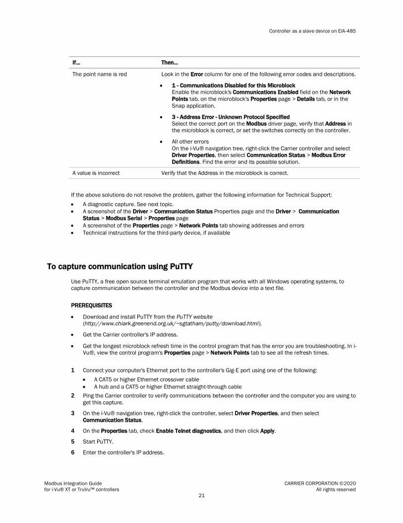
The point name is red Look in the Error column for one of the following error codes and descriptions.
1 - Communications Disabled for this Microblock Enable the microblock's Communications Enabled field on the Network
Points tab, on the microblock's Properties page > Details tab, or in the
Snap application.
3 - Address Error - Unknown Protocol Specified Select the correct port on the Modbus driver page, verify that Address in the microblock is correct, or set the switches correctly on the controller.
All other errors
On the i-Vu® navigation tree, right-click the Carrier controller and select Driver Properties, then select Communication Status > Modbus Error
Definitions. Find the error and its possible solution.
A value is incorrect Verify that the Address in the microblock is correct.
If the above solutions do not resolve the problem, gather the following information for Technical Support:
A diagnostic capture. See next topic.
A screenshot of the Driver > Communication Status Properties page and the Driver > Communication
Status > Modbus Serial > Properties page
A screenshot of the Properties page > Network Points tab showing addresses and errors
Technical instructions for the third-party device, if available
To capture communication using PuTTY
Use PuTTY, a free open source terminal emulation program that works with all Windows operating systems, to capture communication between the controller and the Modbus device into a text file.
PREREQUISITES
Download and install PuTTY from the PuTTY website (http://www.chiark.greenend.org.uk/~sgtatham/putty/download.html).
Get the Carrier controller's IP address.
Get the longest microblock refresh time in the control program that has the error you are troubleshooting. In i-Vu®, view the control program's Properties page > Network Points tab to see all the refresh times.
1 Connect your computer's Ethernet port to the controller's Gig-E port using one of the following:
A CAT5 or higher Ethernet crossover cable
A hub and a CAT5 or higher Ethernet straight-through cable
2 Ping the Carrier controller to verify communications between the controller and the computer you are using to
get this capture.
3 On the i-Vu® navigation tree, right-click the controller, select Driver Properties, and then select
Communication Status.
4 On the Properties tab, check Enable Telnet diagnostics, and then click Apply.
5 Start PuTTY.
6 Enter the controller's IP address.

Controller as a slave device on EIA-485
Modbus Integration Guide CARRIER CORPORATION ©2020
for i-Vu® XT or TruVu™ controllers All rights reserved
22
7 Select Telnet as the Connection Type.
8 Click the Logging option in the upper left corner of the left pane.
9 Select Printable output.
10 Select a location for the capture text file.
11 Click Open to start the session.
12 After Login:>, type: diagport
Press Enter.
13 To capture data receipts, after diagport>, do one of the following:
For Modbus on Port S1, type: modbus1 rx
For Modbus on Port S2, type: modbus2 rx
Press Enter.
14 To capture data transmissions, after diagport>, do one of the following:
For Modbus on Port S1, type: modbus1 tx
For Modbus on Port S2, type: modbus2 tx
Press Enter.
15 To capture more detailed diagnostic messages, after diagport>, do one of the following:
For Modbus on Port S1, type: modbus1 vmsg
For Modbus on Port S2, type: modbus2 vmsg
Press Enter.
16 To capture error messages, after diagport>, do one of the following:
For Modbus on Port S1, type: modbus1 emsg
For Modbus on Port S2, type: modbus2 emsg
Press Enter.
17 Verify the displayed text shows: modbus reporting level status: rx on tx on
flush off fc1 off
fc2 off vmsg on
emsg on off
If rx, tx, vmsg, or emsg show off, repeat the appropriate step (13, 14, 15, or 16) to turn on capture
of that item.
18 After diagport>, type: go
Press Enter.
19 Run the capture for one of the following periods of time:
If all microblock refresh times are one minute or less, run the capture for 5 minutes.
If any microblock refresh time is longer than 1 minute, run the capture for 5 times the longest microblock refresh time.
20 Type: stop
Press Enter. Verify that you see diagport> before doing the next step.
21 After diagport>, type: logout
Press Enter.
22 To end the PuTTY session, click the X in the upper right corner.

Controller as a slave device on EIA-485
Modbus Integration Guide CARRIER CORPORATION ©2020
for i-Vu® XT or TruVu™ controllers All rights reserved
23
23 In the i-Vu® interface, uncheck Enable Telnet diagnostics (see steps 3 and 4), then click Accept.
24 Open the text file from the location you selected in step 11, and then verify that it legibly shows the same
information that PuTTY displayed.
TIP In some cases, you may want the Carrier controller to capture the Telnet diagnostics session and then
upload this capture as part of the system log files. For information on how to do this, see Appendix D (page 55).
Controller as a client device on Ethernet
Modbus Integration Guide CARRIER CORPORATION ©2020
for i-Vu® XT or TruVu™ controllers All rights reserved
24
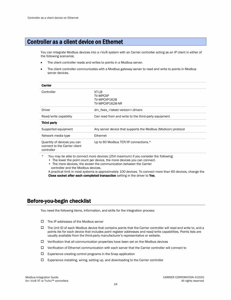
You can integrate Modbus devices into a i-Vu® system with an Carrier controller acting as an IP client in either of the following scenarios:
The client controller reads and writes to points in a Modbus server.
The client controller communicates with a Modbus gateway server to read and write to points in Modbus server devices.
Carrier
Controller XT-LB TV-MPCXP TV-MPCXP1628
TV-MPCXP1628-NR
Driver drv_fwex_<latest version>.driverx
Read/write capability Can read from and write to the third-party equipment
Third party
Supported equipment Any server device that supports the Modbus (Modicon) protocol
Network media type Ethernet
Quantity of devices you can connect to the Carrier client
controller
Up to 60 Modbus TCP/IP connections.*
* You may be able to connect more devices (254 maximum) if you consider the following: • The lower the point count per device, the more devices you can connect. • The more devices, the slower the communication between the Carrier
controller and the Modbus devices. A practical limit in most systems is approximately 100 devices. To connect more than 60 devices, change the
Close socket after each completed transaction setting in the driver to Yes.
Before-you-begin checklist
You need the following items, information, and skills for the integration process:
The IP addresses of the Modbus server
The Unit ID of each Modbus device that contains points that the Carrier controller will read and write to, and a points list for each device that includes point register addresses and read/write capabilities. Points lists are usually available from the third-party manufacturer’s representative or website.
Verification that all communication properties have been set on the Modbus devices
Verification of Ethernet communication with each server that the Carrier controller will connect to
Experience creating control programs in the Snap application
Experience installing, wiring, setting up, and downloading to the Carrier controller
Controller as a client device on Ethernet

Controller as a client device on Ethernet
Modbus Integration Guide CARRIER CORPORATION ©2020
for i-Vu® XT or TruVu™ controllers All rights reserved
25
The integration process
Follow the steps in this section to integrate one or more third-party Modbus devices into a i-Vu® system using the Carrier controller. To install and network the Carrier controller, see the controller's Installation and Start-up Guide.
1 Create a control program in the Snap application
When you create your control program, use a Network I/O microblock for each third-party point.
TIP Verify the third-party manufacturer’s register addressing pattern by establishing communication with a
few points whose values you can physically manipulate before you spend time addressing the remaining integration points.
Formatting a Modbus address
Use the information below to format a valid address in each microblock that you use to read or write to a third-party point.
CAUTION
When integrating third-party devices into a i-Vu® system, most communication problems are caused by incorrect
data or typing errors in the microblock's Address field.
Example: mtcpip://UINT/400128/3/192.168.168.17 (IP address specified directly)
mtcpip://UINT/400128/3/17 (IP address specified indirectly, using index 17)

Controller as a client device on Ethernet
Modbus Integration Guide CARRIER CORPORATION ©2020
for i-Vu® XT or TruVu™ controllers All rights reserved
26
IP Address
You can specify the IP address of the third-party Modbus server either directly or indirectly.
Direct IP address Enter the IP address of the third-party server in dot-decimal notation. For example, 192.168.168.17
Indirect IP address Enter the index number of the IP address to use, For example, 17. You configure the actual IP address corresponding to each index number on the
Driver Properties > Communication Status > Modbus TCP/IP > IP Index Table properties page.
When you use the indirect IP address scheme, you must specify the IP addresses of the third-party Modbus server outside of the control program
logic.
Up to 60 IP addresses can be specified indirectly using the IP Index Table.
Unit ID
If the register address is in... the Unit ID is...
The third-party Modbus server 0 or 255
A device on the third-party Modbus server's serial network 1–254
Register type/Register address
To... this kind of value...
use this microblock...
with this register type...
and a Modbus register address in
this range... 1
Read
0 to 65,535 Unsigned 16-bit integer Input register (3XXXXX)
ANI Uint (not Unit) 300001–365535
0 to 65,535 Unsigned 16-bit integer
Holding register (4XXXXX)
ANI Uint (not Unit) 400001–465535
0 to 4,294,967,296 Unsigned, 32-bit (long) integer
Input register (3XXXXX)
ANI Uint32 300001–365535
0 to 4,294,967,296 Unsigned, 32-bit (long) integer Holding register (4XXXXX)
ANI Uint32 400001–465535
–32,768 to +32,767 Signed 16-bit integer
Input register (3XXXXX)
ANI Sint 300001–365535

Controller as a client device on Ethernet
Modbus Integration Guide CARRIER CORPORATION ©2020
for i-Vu® XT or TruVu™ controllers All rights reserved
27
To... this kind of value...
use this microblock...
with this register type...
and a Modbus register address in
this range... 1
–32,768 to +32,767 Signed 16-bit integer
Holding register (4XXXXX)
ANI Sint 400001–465535
-2,147,483,648 to 2,147,483,647 Signed, 32-bit (long) integer
Input register (3XXXXX)
ANI Sint32 300001–365535
-2,147,483,648 to 2,147,483,647 Signed, 32-bit (long) integer Holding register (4XXXXX)
ANI Sint32 400001–465535
Value with decimal point Input register (3XXXXX)
ANI Float 300001–365535 2
Value with decimal point Holding register (4XXXXX)
ANI Float 400001–465535 2
0 or 1 Coil / Discrete (binary) output
BNI (or ANI)
Do 1–65535 3
0 or 1 Discrete (binary) input (1XXXXX)
BNI (or ANI)
Di 100001–165535
0 or 1 Input register (3XXXXX)
BNI BITn (where n is a value 0-15 defined
in points list)
300001–365535
0 or 1 Holding register (4XXXXX)
BNI BITn (where n is a value 0-15 defined in points list)
400001–465535
To... this kind of value...
use this microblock...
with this register type...
and a Modbus register address in
this range... 1
Write 0 to 65,535 Unsigned 16-bit integer Holding register (4XXXXX)
ANO Uint (not Unit) 400001–465535
–32,768 to +32,767 Signed 16-bit integer
Holding register (4XXXXX)
ANO Sint 400001–465535
Value with decimal point Holding register (4XXXXX)
ANO Float 400001–465535 2
0 or 1 Coil
Discrete (binary) output
BNO (or ANO)
Do 1–65535 3
0 or 1 Holding register (4XXXXX)
BNO (or ANO)
BITn (where n is a value 0-15 defined in points list)
400001–465535

Controller as a client device on Ethernet
Modbus Integration Guide CARRIER CORPORATION ©2020
for i-Vu® XT or TruVu™ controllers All rights reserved
28
1 The Modbus register address (sometimes called register, address, code, or parameter) must be a decimal value.
If the register addresses in the points list include the letters A-F, use a scientific calculator to convert these
hexadecimal values to decimal values.
If the register addresses in the points list are 5-digit numbers in the range #0001-#9999 (where # = the prefix 1, 3, or 4), you may use the addresses as they are, or change them to fit the formats in the table above by shifting the prefix one digit to the left. For example, if you see the address 38129, you can also use 308129.
2 Each Float uses 2 consecutive Modbus register addresses. Use the lower number in the microblock address.
3 Enter the number without any leading zeros. For example, enter 125, not 000125.
64-bit Modbus registers are not supported. See Modbus Troubleshooting (page 44) for more information on register addresses.
Editing a microblock address
You can edit a microblock address in the following places:
In the Snap Property Editor
In the i-Vu® interface, on the microblock's Properties page > Details tab
In the i-Vu® interface, on the control program's Properties page > Network Points tab
2 Download the driver and control programs
In the i-Vu® XT or TruVu™ controller, Modbus communication is already in the standard drv_fwex driver <v103 or later>. You do not need a special Modbus driver.
If you need an updated driver or the latest SAL library, go to Carrier Control Systems Support Site http://www.hvacpartners.com/, https://accounts.ivusystems.com/ and save it to your computer.
To change the driver in the controller
1 Do one of the following:
If the driver is...
In the Driver Version drop-down list a. Select the driver.
b. Click Accept.
Not in the Driver Version drop-down list a. Click Add.
b. Browse to select the driver.
c. Click Open.
d. Click Continue.
e. Click Close.
f. Click Close again.

Controller as a client device on Ethernet
Modbus Integration Guide CARRIER CORPORATION ©2020
for i-Vu® XT or TruVu™ controllers All rights reserved
29
2 Click the Download All Content button.
3 Click OK.
4 Click Accept.
To update the SAL library in the i-Vu® application
1 In the i-Vu® interface, click System Menu , then select System Options > Update.
NOTE Expand Current Libraries (.sal) to see the current SAL libraries and their revision. Compare them to what you downloaded and determine if any of them need updating.
2 Click and browse to the updated .sal file that you have saved on your computer, select the file, and click Open.
3 Click Continue.
4 When process is complete, the message appears File added successfully.
5 Click Close.
6 Click Close again.
7 Click the Download All Content button.
8 Click OK.
9 Click Accept.
To add a control program
NOTE i-Vu® Pro - Place the .equipment file in i-Vu_Pro_x.x\webroot\<system_name>\programs.
1 In the i-Vu® interface, select the router in the navigation tree and go to the Devices > Manage tab.
2 Select the controller in the list on the page.
3 If you are adding a new control program, click the Add Control Program button . A dialog window appears.
4 Enter a name for your control program in Display Name and select your controller in the Controller drop-down
list.
5 Do one of the following:
If the control program is...
In the Control Program drop-down list Select the control program.
Not in the Control Program drop-down list a. Click Add New.
b. Browse to select the control program.
c. Click Open.
d. Click Continue.
e. Click Close.
6 Click Continue. When message appears File added successfully, click Close.

Controller as a client device on Ethernet
Modbus Integration Guide CARRIER CORPORATION ©2020
for i-Vu® XT or TruVu™ controllers All rights reserved
30
7 Click Close again.
8 Right-click on the controller in the list and select Check Status from the list. The status of the controller
should say File Mismatch.
9 Click the Download All Content button.
3 Connect the Carrier controller to the third-party device
Use one of the following CAT5 or higher Ethernet cables:
A cross-over cable to connect the Carrier controller directly to the third-party Modbus device
A straight-through cable to connect the controller to a hub or switch, and a second straight-through cable to
connect the hub or switch to the third-party Modbus device
Maximum cable length: 328 feet (100 meters)
1 Turn off the Carrier controller's power.
2 Check the communications wiring for shorts and grounds.
3 Wire the Carrier controller's Gig-E port to the third-party device.
NOTE Gig-E port is also capable of BACnet communication.
4 Turn on the Carrier controller's power.
4 Set up the driver properties
1 On the navigation tree, right-click the controller and select Driver Properties.
2 Expand Communication Status, then select Modbus TCP/IP.
3 Under Port Configuration, select TCP/IP as the Communication Type.
4 The standard Modbus TCP Port is 502. If a different port is to be used, type the port number. Select the
Details checkbox for help.
5 Under Modbus Protocol Configuration, set Modbus TCP/IP Mode to Client.
6 Set the remaining fields under Modbus Protocol Configuration using information from the third-party
manufacturer's representative. Select the Details checkbox for help.
7 If the Carrier controller has more than 60 TCP/IP connections, under TCP/IP Protocol Configuration, change
Close socket after each completed transaction to Yes.
NOTES
If you connect more than 60 devices (256 maximum), consider the following:
• The lower the point count per device, the more devices you can connect.
• The more devices, the slower the communication between the Carrier controller and the Modbus devices.
• A practical limit in most systems is approximately 100 devices.
Controller as a client device on Ethernet
Modbus Integration Guide CARRIER CORPORATION ©2020
for i-Vu® XT or TruVu™ controllers All rights reserved
31
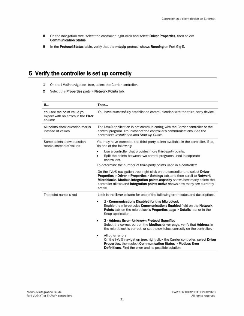
8 On the navigation tree, select the controller, right-click and select Driver Properties, then select
Communication Status.
9 In the Protocol Status table, verify that the mtcpip protocol shows Running on Port Gig-E.
5 Verify the controller is set up correctly
1 On the i-Vu® navigation tree, select the Carrier controller.
2 Select the Properties page > Network Points tab.
If... Then...
You see the point value you expect with no errors in the Error column
You have successfully established communication with the third-party device.
All points show question marks instead of values
The i-Vu® application is not communicating with the Carrier controller or the control program. Troubleshoot the controller's communications. See the controller's Installation and Start-up Guide.
Some points show question marks instead of values
You may have exceeded the third-party points available in the controller. If so, do one of the following:
Use a controller that provides more third-party points.
Split the points between two control programs used in separate
controllers.
To determine the number of third-party points used in a controller:
On the i-Vu® navigation tree, right-click on the controller and select Driver Properties > Driver > Properties > Settings tab, and then scroll to Network
Microblocks. Modbus integration points capacity shows how many points the controller allows and integration points active shows how many are currently
active.
The point name is red Look in the Error column for one of the following error codes and descriptions.
1 - Communications Disabled for this Microblock
Enable the microblock's Communications Enabled field on the Network Points tab, on the microblock's Properties page > Details tab, or in the
Snap application.
3 - Address Error - Unknown Protocol Specified Select the correct port on the Modbus driver page, verify that Address in the microblock is correct, or set the switches correctly on the controller.
All other errors
On the i-Vu® navigation tree, right-click the Carrier controller, select Driver Properties, then select Communication Status > Modbus Error
Definitions. Find the error and its possible solution.

Controller as a client device on Ethernet
Modbus Integration Guide CARRIER CORPORATION ©2020
for i-Vu® XT or TruVu™ controllers All rights reserved
32
If... Then...
A value is incorrect Verify that:
The Address in the microblock is correct.
The retrieved value is scaled properly, if necessary. For example, scaled from Celsius to Fahrenheit. Refer to the third-party manufacturer's
documentation or the controller's Installation and Start-up Guide for scaling information.
If the above solutions do not resolve the problem, gather the following information for Technical Support:
A diagnostic capture using Wireshark. See the following section for Wireshark instructions.
NOTE If directed by Technical Support, you can use PuTTY to get a diagnostic capture. PuTTY instructions are after the Wireshark instructions.
A screenshot of the driver's Communication Status and Modbus TCP/IP pages.
A screenshot of the Properties page > Network Points tab showing addresses and errors
All information from a Modstat copied into a text file.
Right-click the Modstat, then select Select All. Press Ctrl+C to copy the information, then open Notepad and paste the information into a text file.
Technical instructions for the third-party device, if available
To capture communication using Wireshark
Use Wireshark, a network analysis tool, to capture the Ethernet communication between the Carrier controller and the Modbus device.
PREREQUISITE Provide an Ethernet hub (not a switch) so that Wireshark can capture all Ethernet communication, not just broadcasts.
1 Download the latest version of Wireshark from the Wireshark website (http://www.wireshark.org).
2 Run the Wireshark install program, accepting all defaults. Include WinPcap in the installation.
3 Disconnect the network cable from the Carrier controller's Gig-E port, then plug the cable into the hub's
Uplink port.
4 Use a separate Ethernet cable to connect the controller's Gig-E port to the hub.
5 Connect the Modbus device's Ethernet cable to the hub.
6 Connect the Ethernet port of the computer running Wireshark to the hub.
7 On the computer, click Start > All Programs > Wireshark.
8 From the menu bar, select Capture > Interfaces.

Controller as a client device on Ethernet
Modbus Integration Guide CARRIER CORPORATION ©2020
for i-Vu® XT or TruVu™ controllers All rights reserved
33
9 Click the Start button next to the adapter that is connected to the network. This starts the IP capture.
TIP Choose the adapter that shows the Packets value changing.
10 Allow the capture to run long enough to ensure that there is sufficient data to allow a technician to review the problem.
11 On the menu bar, select Capture > Stop to stop the data capture.
12 Select File > Save and save the capture to a convenient location. Leave the Save as type default set to
Wireshark/tcpdump/… - libpcap (*.pcap, *.cap).
13 Send the file to Carrier Technical Support for analysis.
TIP You can color code the information in the Wireshark capture file based on user-defined criteria. See Wireshark's Help for instructions on setting up Coloring Rules.
To capture communication using PuTTY
Use PuTTY, a free open source terminal emulation program that works with all Windows operating systems, to capture communication between the controller and the Modbus device into a text file.
PREREQUISITES
Download and install PuTTY from the PuTTY website (http://www.chiark.greenend.org.uk/~sgtatham/putty/download.html).
Get the Carrier controller's IP address.
Get the longest microblock refresh time in the control program that has the error you are troubleshooting. In i-Vu®, view the control program's Properties page > Network Points tab to see all the refresh times.
1 Connect your computer's Ethernet port to the controller's Port Gig-E using one of the following:
A CAT5 or higher Ethernet crossover cable
A hub and a CAT5 or higher Ethernet straight-through cable
2 Ping the Carrier controller to verify communications between the controller and the computer you are using to
get this capture.
3 On the i-Vu® navigation tree, right-click the Carrier controller, select Driver Properties, then select
Communication Status
4 On the Properties tab, check Enable Telnet diagnostics, and then click Apply.
5 Start PuTTY.
6 Enter the controller's IP address.
7 Select Telnet as the Connection Type.
8 Click the Logging option in the upper left corner of the left pane.
9 Select Printable output.
10 Select a location for the capture text file.
11 Click Open to start the session.

Controller as a client device on Ethernet
Modbus Integration Guide CARRIER CORPORATION ©2020
for i-Vu® XT or TruVu™ controllers All rights reserved
34
12 After Login:>, type: diagport
Press Enter.
13 To capture data receipts, after diagport>, type: mtcpip rx
Press Enter.
14 To capture data transmissions, after diagport>, type: mtcpip tx
Press Enter.
15 To capture more detailed diagnostic messages, after diagport>, type: mtcpip vmsg
Press Enter.
16 To capture error messages, after diagport>, type: mtcpip emsg
Press Enter.
17 Verify the displayed text shows: modbus reporting level status: rx on tx on flush off fc1 off fc2 off vmsg on emsg on off
If rx, tx, vmsg, or emsg show off, repeat the appropriate step (13, 14, 15, or 16) to turn on capture
of that item.
18 After diagport>, type: go
Press Enter.
19 Run the capture for one of the following periods of time:
If all microblock refresh times are one minute or less, run the capture for 5 minutes.
If any microblock refresh time is longer than 1 minute, run the capture for 5 times the longest microblock
refresh time.
20 Type: stop
Press Enter. Verify that you see diagport> before doing the next step.
21 After diagport>, type: logout
Press Enter.
22 To end the PuTTY session, click the X in the upper right corner.
23 In the i-Vu® interface, uncheck Enable Telnet diagnostics (see steps 3 and 4), and then click Accept.
24 Open the text file from the location you selected in step 11, and then verify that it legibly shows the same
information that PuTTY displayed.
TIP In some cases, you may want the Carrier controller to capture the Telnet diagnostics session and then upload this capture as part of the system log files. For information on how to do this, see Appendix D (page 55).

Controller as a server device on Ethernet
Modbus Integration Guide CARRIER CORPORATION ©2020
for i-Vu® XT or TruVu™ controllers All rights reserved
35
Carrier
Controller XT-LB TV-MPCXP TV-MPCXP1628
TV-MPCXP1628-NR
Driver drv_fwex_<latest version>.driverx
Read/write capability Can be read from and written to
Third party
Supported equipment Any device that supports the Modbus (Modicon) protocol
Network media type Ethernet
Quantity of devices you can connect to the Carrier controller
Up to 3 Modbus client devices
Up to 254 Modbus slaves on EIA-485
Before-you-begin checklist
You need the following items, information, and skills for the integration process:
A list of the points in the Carrier controller that the Modbus client will read or write to.
Verification that all communication properties have been set on the Modbus devices
Verification of Ethernet communication with each Modbus client that the Carrier controller will connect to
Experience creating control programs in the Snap application
Experience installing, wiring, setting up, and downloading to the Carrier controller
The integration process
Follow the steps in this section to integrate the Carrier controller into a Modbus system. To install and network the Carrier controller, see the controller's Installation and Start-up Guide.
Controller as a server device on Ethernet

Controller as a server device on Ethernet
Modbus Integration Guide CARRIER CORPORATION ©2020
for i-Vu® XT or TruVu™ controllers All rights reserved
36
1 Create a control program in the Snap application
When you create your control program, use a Network I/O microblock for each value that you want to expose to the Modbus client.
Formatting a Modbus address
Use the information below to format a valid address for each value that you want to expose to the Modbus client.
CAUTION When integrating third-party devices into a i-Vu® system, most communication problems are caused by incorrect
data or typing errors in the microblock's Address field.
Example: mtcpip://UINT/400128
Register type/Register address
When the Carrier controller is a server device, you must expose its points so that they can be read or written to by a third-party client device.
For a third-party device
to...
this kind of exposed value in the Carrier controller...
use this microblock...
with this register type...
and a Modbus register address in
this range...
Write
0 to 65,535 Unsigned 16-bit integer
Holding register (4XXXXX)
ANI Uint (not Unit) 400001–465535
–32,768 to +32,767 Signed 16-bit integer Holding register (4XXXXX)
ANI Sint 400001–465535
Value with decimal point Holding register (4XXXXX)
ANI Float 400001–465535

Controller as a server device on Ethernet
Modbus Integration Guide CARRIER CORPORATION ©2020
for i-Vu® XT or TruVu™ controllers All rights reserved
37
For a third-party device to...
this kind of exposed value in the Carrier controller...
use this microblock...
with this register type...
and a Modbus register address in this range...
0 or 1 Coil Discrete (binary) output
BNI Do 1–65535 3
Read
0 to 65,535 Unsigned 16-bit integer
Input register (3XXXXX)
ANO Uint (not Unit) 300001–365535
0 to 65,535 Unsigned 16-bit integer
Holding register (4XXXXX)
ANO Uint (not Unit) 400001–465535
–32,768 to +32,767 Signed 16-bit integer Input register (3XXXXX)
ANO Sint 300001–365535
–32,768 to +32,767 Signed 16-bit integer
Holding register (4XXXXX)
ANO Sint 400001–465535
Value with decimal point Input register (3XXXXX)
ANO Float 300001–365535
Value with decimal point Holding register (4XXXXX)
ANO Float 400001–465535
0 or 1 Coil
Discrete (binary) output
BNO Do 1–65535 3
0 or 1 Discrete (binary) input (1XXXXX)
BNO Di 100001–165535
1 If the register addresses in the points list are 5-digit numbers in the range #0001-#9999 (where # = the prefix
1, 3, or 4), you may use the addresses as they are, or change them to fit the formats in the table above by shifting the prefix one digit to the left. For example, if you see the address 38129, you can also use 308129.
2 Each Float uses 2 consecutive Modbus register addresses. Use the lower number in the microblock address.
3 Enter the number without any leading zeros. For example, enter 125, not 000125.
4
64-bit Modbus registers are not supported. See Modbus Troubleshooting (page 44) for more information on register addresses.
Editing a microblock address
You can edit a microblock address in the following places:
In the Snap Property Editor
In the i-Vu® interface, on the microblock's Properties page > Details tab
In the i-Vu® interface, on the control program's Properties page > Network Points tab
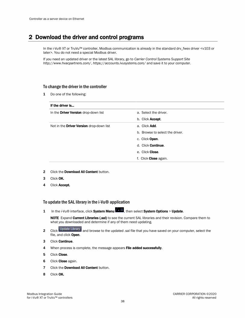
Controller as a server device on Ethernet
Modbus Integration Guide CARRIER CORPORATION ©2020
for i-Vu® XT or TruVu™ controllers All rights reserved
38
2 Download the driver and control programs
In the i-Vu® XT or TruVu™ controller, Modbus communication is already in the standard drv_fwex driver <v103 or later>. You do not need a special Modbus driver.
If you need an updated driver or the latest SAL library, go to Carrier Control Systems Support Site http://www.hvacpartners.com/, https://accounts.ivusystems.com/ and save it to your computer.
To change the driver in the controller
1 Do one of the following:
If the driver is...
In the Driver Version drop-down list a. Select the driver.
b. Click Accept.
Not in the Driver Version drop-down list a. Click Add.
b. Browse to select the driver.
c. Click Open.
d. Click Continue.
e. Click Close.
f. Click Close again.
2 Click the Download All Content button.
3 Click OK.
4 Click Accept.
To update the SAL library in the i-Vu® application
1 In the i-Vu® interface, click System Menu , then select System Options > Update.
NOTE Expand Current Libraries (.sal) to see the current SAL libraries and their revision. Compare them to what you downloaded and determine if any of them need updating.
2 Click and browse to the updated .sal file that you have saved on your computer, select the file, and click Open.
3 Click Continue.
4 When process is complete, the message appears File added successfully.
5 Click Close.
6 Click Close again.
7 Click the Download All Content button.
8 Click OK.
Controller as a server device on Ethernet
Modbus Integration Guide CARRIER CORPORATION ©2020
for i-Vu® XT or TruVu™ controllers All rights reserved
39
9 Click Accept.
To add a control program
NOTE i-Vu® Pro - Place the .equipment file in i-Vu_Pro_x.x\webroot\<system_name>\programs.
1 In the i-Vu® interface, select the router in the navigation tree and go to the Devices > Manage tab.
2 Select the controller in the list on the page.
3 If you are adding a new control program, click the Add Control Program button . A dialog window appears.
4 Enter a name for your control program in Display Name and select your controller in the Controller drop-down
list.
5 Do one of the following:
If the control program is...
In the Control Program drop-down list Select the control program.
Not in the Control Program drop-down list a. Click Add New.
b. Browse to select the control program.
c. Click Open.
d. Click Continue.
e. Click Close.
6 Click Continue. When message appears File added successfully, click Close.
7 Click Close again.
8 Right-click on the controller in the list and select Check Status from the list. The status of the controller
should say File Mismatch.
9 Click the Download All Content button.
3 Connect the Carrier controller to the third-party device
Use one of the following CAT5 or higher Ethernet cables:
A cross-over cable to connect the Carrier controller directly to the third-party Modbus device
A straight-through cable to connect the controller to a hub or switch, and a second straight-through cable to connect the hub or switch to the third-party Modbus device
Maximum cable length: 328 feet (100 meters)

Controller as a server device on Ethernet
Modbus Integration Guide CARRIER CORPORATION ©2020
for i-Vu® XT or TruVu™ controllers All rights reserved
40
1 Turn off the Carrier controller's power.
2 Check the communications wiring for shorts and grounds.
3 Wire the Carrier controller's Gig-E port to the third-party device.
NOTE Gig-E port is also capable of BACnet communication.
4 Turn on the Carrier controller's power.
4 Set up the driver properties
1 On the navigation tree, right-click the controller and select Driver Properties.
2 Expand Communication Status, then select Modbus TCP/IP.
3 Under Port Configuration, select TCP/IP as the Communication Type.
4 The standard Modbus TCP Port is 502. If a different port is to be used, type the port number. Select the
Details checkbox for help.
5 Under Modbus Protocol Configuration, set Modbus TCP/IP Mode to Server.
6 On the Driver Properties tree, select Communication Status.
7 In the Protocol Status table, verify that the mtcpip protocol shows Running on Port Gig-E.
5 Verify the controller is set up correctly
1 On the i-Vu® navigation tree, select the Carrier controller.
2 Select the Properties page > Network Points tab.
If... Then...
You see the point value you expect and the Error column shows Initializing
You have successfully exposed the Carrier controller's value to the third-party device.
All points show question marks instead of values
The i-Vu® application is not communicating with the Carrier controller or the control program. Troubleshoot the controller's communications. See the controller's
Installation and Start-up Guide.
Some points show question marks instead of values
You may have exceeded the third-party points available in the controller. If so, do one of the following:
Use a controller that provides more third-party points.
Split the points between two control programs used in separate controllers.
To determine the number of third-party points used in a controller:
On the i-Vu® navigation tree, right-click on the controller and select Driver Properties > Driver > Properties > Settings tab, and then scroll to Network
Microblocks. Modbus integration points capacity shows how many points the controller allows and integration points active shows how many are currently active.

Controller as a server device on Ethernet
Modbus Integration Guide CARRIER CORPORATION ©2020
for i-Vu® XT or TruVu™ controllers All rights reserved
41
If... Then...
The point name is red Look in the Error column for one of the following error codes and descriptions.
1 - Communications Disabled for this Microblock Enable the microblock's Communications Enabled field on the Network Points
tab, on the microblock's Properties page > Details tab, or in the Snap
application.
3 - Address Error - Unknown Protocol Specified Select the correct port on the Modbus driver page in i-Vu®, verify that Address in the microblock is correct, or set the switches correctly on the controller.
All other errors
On the i-Vu® navigation tree, right-click the Carrier controller, select Driver Properties, then select Communication Status > Modbus Error Definitions. Find
the error and its possible solution.
A value is incorrect Verify that the Address in the microblock is correct.
If the above solutions do not resolve the problem, gather the following information for Technical Support:
A diagnostic capture using Wireshark. See the following section for Wireshark instructions.
NOTE If directed by Tech Support, you can use PuTTY to get a diagnostic capture. PuTTY instructions are after the Wireshark instructions.
A screenshot of the driver's Communication Status and Modbus TCP/IP pages.
A screenshot of the Properties page > Network Points tab showing addresses and errors
All information from a Modstat copied into a text file.
Right-click the Modstat, then select Select All. Press Ctrl+C to copy the information, then open Notepad and paste the information into a text file.
Technical instructions for the third-party device, if available
To capture communication using Wireshark
Use Wireshark, a network analysis tool, to capture the Ethernet communication between the Carrier controller and the Modbus device.
PREREQUISITE Provide an Ethernet hub (not a switch) so that Wireshark can capture all Ethernet communication, not just broadcasts.
1 Download the latest version of Wireshark from the Wireshark website (http://www.wireshark.org).
2 Run the Wireshark install program, accepting all defaults. Include WinPcap in the installation.
3 Disconnect the network cable from the Carrier controller's Gig-E port, then plug the cable into the hub's
Uplink port.
4 Use a separate Ethernet cable to connect the controller's Gig-E port to the hub.
5 Connect the Modbus device's Ethernet cable to the hub.
6 Connect the Ethernet port of the computer running Wireshark to the hub.
7 On the computer, click Start > All Programs > Wireshark.

Controller as a server device on Ethernet
Modbus Integration Guide CARRIER CORPORATION ©2020
for i-Vu® XT or TruVu™ controllers All rights reserved
42
8 From the menu bar, select Capture > Interfaces.
9 Click the Start button next to the adapter that is connected to the network. This starts the IP capture.
TIP Choose the adapter that shows the Packets value changing.
10 Allow the capture to run long enough to ensure that there is sufficient data to allow a technician to review the problem.
11 On the menu bar, select Capture > Stop to stop the data capture.
12 Select File > Save and save the capture to a convenient location. Leave the Save as type default set to
Wireshark/tcpdump/… - libpcap (*.pcap, *.cap).
13 Send the file to Carrier Technical Support for analysis.
TIP You can color code the information in the Wireshark capture file based on user-defined criteria. See Wireshark's Help for instructions on setting up Coloring Rules.
To capture communication using PuTTY
Use PuTTY, a free open source terminal emulation program that works with all Windows operating systems, to capture communication between the controller and the Modbus device into a text file.
PREREQUISITES
Download and install PuTTY from the PuTTY website (http://www.chiark.greenend.org.uk/~sgtatham/putty/download.html).
Get the Carrier controller's IP address.
Get the longest microblock refresh time in the control program that has the error you are troubleshooting. In i-
Vu®, view the control program's Properties page > Network Points tab to see all the refresh times.
1 Connect your computer's Ethernet port to the controller's Port Gig-E using one of the following:
A CAT5 or higher Ethernet crossover cable
A hub and a CAT5 or higher Ethernet straight-through cable
2 Ping the Carrier controller to verify communications between the controller and the computer you are using to
get this capture.
3 On the i-Vu® navigation tree, right-click the Carrier controller, select Driver Properties, then select
Communication Status

Controller as a server device on Ethernet
Modbus Integration Guide CARRIER CORPORATION ©2020
for i-Vu® XT or TruVu™ controllers All rights reserved
43
4 On the Properties tab, check Enable Telnet diagnostics, and then click Apply.
5 Start PuTTY.
6 Enter the controller's IP address.
7 Select Telnet as the Connection Type.
8 Click the Logging option in the upper left corner of the left pane.
9 Select Printable output.
10 Select a location for the capture text file.
11 Click Open to start the session.
12 After Login:>, type: diagport
Press Enter.
13 To capture data receipts, after diagport>, type: mtcpip rx
Press Enter.
14 To capture data transmissions, after diagport>, type: mtcpip tx
Press Enter.
15 To capture more detailed diagnostic messages, after diagport>, type: mtcpip vmsg
Press Enter.
16 To capture error messages, after diagport>, type: mtcpip emsg
Press Enter.
17 Verify the displayed text shows: modbus reporting level status: rx on
tx on
flush off
fc1 off
fc2 off
vmsg on
emsg on
off
If rx, tx, vmsg, or emsg show off, repeat the appropriate step (13, 14, 15, or 16) to turn on capture of that item.
18 After diagport>, type: go
Press Enter.
19 Run the capture for one of the following periods of time:
If all microblock refresh times are one minute or less, run the capture for 5 minutes.
If any microblock refresh time is longer than 1 minute, run the capture for 5 times the longest microblock
refresh time.
20 Type: stop
Press Enter. Verify that you see diagport> before doing the next step.
21 After diagport>, type: logout
Press Enter.
22 To end the PuTTY session, click the X in the upper right corner.
23 In the i-Vu® interface, uncheck Enable Telnet diagnostics (see steps 3 and 4), and then click Accept.
24 Open the text file from the location you selected in step 11, and then verify that it legibly shows the same
information that PuTTY displayed.
TIP In some cases, you may want the Carrier controller to capture the Telnet diagnostics session and then
upload this capture as part of the system log files. For information on how to do this, see Appendix D (page 55).

Modbus Troubleshooting
Modbus Integration Guide CARRIER CORPORATION ©2020
for i-Vu® XT or TruVu™ controllers All rights reserved
44
The following troubleshooting information depends on whether your Carrier controller is a master/client or a slave/server.
In most cases, a diagnostic capture can help determine the problem. See To capture communication using … in the appropriate section of this document.
If the Carrier controller is a Serial Master or Ethernet Client
Register addresses
Because Modbus register address formats differ from one manufacturer to another, the most common problems in a Modbus integration are caused by a microblock address having an incorrect register address.
If the Carrier controller is a serial master or Ethernet client, the register address that you include in a microblock address is the register address that you want to read from/write to in the slave/server. Microblocks support
Modbus register addresses that consist of a base register address (1–65535) and a one digit prefix (except coils) that defines the type of value.
This type of value... Has the prefix... Example of register address
Discrete input 1 103459 or 13459
Input register 3 304564 or 34564
Holding register 4 401563 or 41563
Coil No prefix
Base address Most manufacturers begin counting register addresses at 1; some begin at 0. Other than contacting the manufacturer to get clarification, you can look at the register address list to see if the addressing in any table
starts at 0. If any table's addressing begins at 0, you need to add 1 to each register address in order to read the right register. For example, if you are given a register address of 40100, you must enter the address as 40101 to
read the correct register.
Prefix Some manufacturers include the prefix in their register address. If you add another prefix, you will have an invalid register address. For example, if the third-party manufacturer shows a holding register address is 40123 and you
add the prefix 4, your register address will be 440123, which is an invalid address.
Modbus Troubleshooting

Modbus Troubleshooting
Modbus Integration Guide CARRIER CORPORATION ©2020
for i-Vu® XT or TruVu™ controllers All rights reserved
45
Errors
If the Properties page > Network Points tab shows errors, look for the error in the table below. To see a more extensive list, right-click the controller in the navigation tree, select Driver Properties > Driver > Communication
Status > Modbus Error Definitions.
Error code/message Possible solution(s)
Error ## - Modbus Exception Code - XXXX
Where: ## = a number from 51 to 61, and
XXXX = the exception code description
A server/slave device returns a Modbus Exception Code when it cannot respond to the master/client. The most common are:
ILLEGAL FUNCTION: The master/client sends an unsupported function code to the slave/server. For example, the master/client tries to query with function
code 16, which is not supported by the slave/server.
NOTE Some manufacturers do not support: Function Code 15—Write Multiple Coils, or Function Code 16—Write Multiple Registers
To resolve this, right-click the controller in the navigation tree, select Driver Properties > Driver > Communication Status > Modbus TCP/IP. Set Restrict coil and register commands to Yes.
ILLEGAL DATA ADDRESS: The master/client sends an invalid register address
to the slave/server. For example, the master/client tries to read register 500, but the highest register address is 100. To resolve this error, correct the
register address.
ILLEGAL DATA VALUE: The master/client sends an invalid value to the slave/server. For example, the master/client tries to write a decimal value 150 to a Modbus Coil. To resolve this error, change the value you are writing to a
value the register can accept.
Error 94 - Response Err – Invalid Exception Code
Although rare, the Exception Code returned by the Modbus slave/server device may be incorrect. Valid Exception Code range is 1 to 11 (except 9). Use a
diagnostic capture to determine the invalid exception code. Then contact the third-party manufacturer for a resolution.
Error 72 – Addr Err – Invalid Register Number
Prefix
or
Error 73 – Addr Err – Invalid Register Number
Range
See Register Addresses (page 44).
Error 78 – Addr Err – Invalid Duplicates Found
You cannot have multiple ANO/BNO microblocks in the same controller write to the same address. If you have duplicates, only one will be processed. Remove all
duplicates, and then download memory.
NOTE You can have multiple ANI/BNI microblocks read from the same address.

Modbus Troubleshooting
Modbus Integration Guide CARRIER CORPORATION ©2020
for i-Vu® XT or TruVu™ controllers All rights reserved
46
Error code/message Possible solution(s)
Error 79 – Addr Err – Possible Overlapped Register
This error indicates registers that share a common address.
For example: Modbus://FLOAT/401000/58
Modbus://UINT/401001/58
In this example, the FLOAT register type uses two register addresses, 1000 and 1001. So, the UINT's register address overlaps the FLOAT's 1001 address. The last microblock processed will get an error. To find the issue, the application
programmer should check the previous and next sequential microblock register addresses.
Error 11 – Unable to allocate packet
Although rare, you may see this error if you have a large number of network points (more than 250) and most microblocks have a Refresh Time of 10 seconds or less.
To resolve this, increase the Refresh Time on non-critical points. Critical points can still be updated more frequently.
As described below, you can use diagnostic captures to fine-tune your system to make the most of the available bandwidth. See To capture communication using …
in the appropriate section of this document. Only turn on the vmsg (verbose message) to see how the points are queried.
Serial Master By looking at the capture, the engineer can follow how efficient the query may be. Look at the bolded packets below. The Master reads from device 58, Function
Code 3 (Read Holding Reg) and register address 1 through 3, for the total of 3 registers. This packet is repeated twice in sequence, which may not be desirable.
To resolve this, change the refresh time of microblocks with register address 2 and 3 to 10 minutes (or larger). Register addresses 2 and 3 will be read and updated
when register address 1 is read and will only trigger an update if register address 1 is removed from the application. Observe the capture and make sure that the
repetition is resolved.
MODBUS<VM>READ Dev:58 - FC:3 - Reg:601 -> 603 - Qty:3 MODBUS<VM>READ Dev:58 - FC:3 - Reg:1 -> 3 - Qty:3 MODBUS<VM>READ Dev:58 - FC:3 - Reg:1 -> 3 - Qty:3
MODBUS<VM>READ Dev:58 - FC:3 - Reg:601 -> 603 - Qty:3 MODBUS<VM>READ Dev:58 - FC:3 - Reg:1 -> 3 - Qty:3
MODBUS<VM>READ Dev:58 - FC:3 - Reg:401 -> 406 - Qty:6 MODBUS<VM>READ Dev:58 - FC:4 - Reg:2001 -> 2009 - Qty:9
MODBUS<VM>READ Dev:58 - FC:4 - Reg:1001 -> 1009 - Qty:9 MODBUS<VM>READ Dev:58 - FC:4 - Reg:601 -> 603 - Qty:3
MODBUS<VM>READ Dev:58 - FC:4 - Reg:301 -> 306 - Qty:6 MODBUS<VM>READ Dev:58 - FC:4 - Reg:201 -> 206 - Qty:6
MODBUS<VM>READ Dev:58 - FC:4 - Reg:101 -> 103 - Qty:3 MODBUS<VM>READ Dev:58 - FC:4 - Reg:1 -> 3 - Qty:3

Modbus Troubleshooting
Modbus Integration Guide CARRIER CORPORATION ©2020
for i-Vu® XT or TruVu™ controllers All rights reserved
47
Error code/message Possible solution(s)
IP Client Use the same techniques described above for the Serial Master. Look at the bolded packets below. The client reads from Device IP 161.145.174.36 with
device address 0. It reads register 65532 through 65535 twice sequentially. To resolve this, change the refresh time to 10 minutes (or larger) for each microblock
in the group except for the first microblock with register address 65532. Register addresses 65533 through 65535 will be read and updated when register address
65532 is read, and will only trigger an update if register address 65532 is removed from the application.
MTCPIP<VM>Rx response ID:44 MTCPIP<VM>Rx response ID:45
MTCPIP<VM>READ Dev IP:161.145.174.236 - Addr:0 - FC:3 - Reg:40009 -> 40016 - Qty:8 - ID:55
MTCPIP<VM>READ Dev IP:161.145.174.236 - Addr:0 - FC:3 - Reg:40000 -> 40007 - Qty:8 - ID:56
MTCPIP<VM>READ Dev IP:161.145.174.236 - Addr:0 - FC:3 - Reg:1 -> 12 - Qty:12 - ID:57
MTCPIP<VM>Rx response ID:46 MTCPIP<VM>Rx response ID:47
MTCPIP<VM>READ Dev IP:161.145.174.236 - Addr:0 - FC:2 - Reg:65532 -> 65535 - Qty:4 - ID:58
MTCPIP<VM>READ Dev IP:161.145.174.236 - Addr:0 - FC:1 - Reg:65532 -> 65535 - Qty:4 - ID:59
MTCPIP<VM>READ Dev IP:161.145.174.236 - Addr:0 - FC:1 - Reg:65532 ->
65535 - Qty:4 - ID:60 MTCPIP<VM>Rx response ID:48
MTCPIP<VM>Rx response ID:49
Error 86 – Unable to update point value
The microblock value is not updating.
Serial Master In rare cases, the master may receive a valid response but cannot match it to any
microblock. The only way to determine this is to review a diagnostic capture. To resolve, right-click the controller in the navigation tree, select Driver Properties >
Driver > Communication Status > Modbus Serial page, and increase the Interpacket Delay. This solution is not desirable if the controller's point count is
high.
IP Client Because Modbus TC/IP does not have a timeout defined, this error may occur when the client communicates with a very slow server. If a client microblock with a
low refresh time (1 second) sends a query every second but the server requires more than 2 seconds to respond, this error will be set on the microblocks after a
few cycles of queries. Get a diagnostic capture using Wireshark to see the timing between query and response. Increase the refresh time to allow the server to
respond before a new request is sent. This solution will slow communication between the server and client controllers.

Modbus Troubleshooting
Modbus Integration Guide CARRIER CORPORATION ©2020
for i-Vu® XT or TruVu™ controllers All rights reserved
48
Error code/message Possible solution(s)
Error 40 – No response Serial Master If the error is persistent, check the wiring, communication baud rate, and device address.
If it is intermittent, right-click the controller in the navigation tree, select Driver Properties > Driver > Communication Status > Modbus Serial page, and try
changing the following settings:
Increase the Interpacket Delay in increments of 10 ms. Maximum recommended is 100 ms, depending on the size of control program. The bigger
the control program is, the smaller this setting should be.
If the query reads multiple registers, try reducing the size of Maximum Registers to Request. Use the diagnostics capture to determine where the issue is most likely to occur. If you need to reduce multiple registers, set the
Maximum Registers to Request and/or Maximum Coils/DIs to Request to 1. You can optimize later if needed.
If the query writes to multiple registers, you may want to inhibit multiple write altogether. Use the diagnostics capture to determine where the issue is most likely to occur. In most cases, the slave device is more susceptible to multiple
writes. To inhibit multiple registers writes, set Restrict coil and register commands to Yes.
IP Client TCP/IP communication is successful, but the Modbus packet never gets a
response from the Modbus server. Talk to the third-party vendor to determine the reason the server is not responding.
No microblock error, but a float value is not correct
FLOAT register types use 2 register addresses. The order in which they are processed differs from one manufacturer to another. If you see incorrect float values, right-click the controller in the navigation tree, select Driver Properties >
Driver > Communication Status > Modbus TCP/IP. Change the value of the Reverse Float/32 Bit Integer field.
CAUTION This setting is applied globally for all float values in the controller. If
you have some float registers that are to be processed one way and others that are to be processed the other way, you must use separate master/client devices to talk
to them.
If the Carrier controller is a Serial Slave or Ethernet Server
Register addresses
If the Carrier controller is a slave/server, register addresses are 1-based, not 0-based, and do not require any adjustment as long as the serial master or Ethernet client adheres to the Modbus protocol implementation
described on the Modbus website (www.modbus.org).

Modbus Troubleshooting
Modbus Integration Guide CARRIER CORPORATION ©2020
for i-Vu® XT or TruVu™ controllers All rights reserved
49
If the Carrier controller is a slave/server, the register address that you include in a microblock address is the register address that you want to expose to master/client. Microblocks support Modbus register addresses that
consist of a base register address (1–65535) and a one digit prefix (except coils) that defines the type of value.
This type of value... Has the prefix... Example of register address
Discrete input 1 103459 or 13459
Input register 3 304564 or 34564
Holding register 4 401563 or 41563
Coil No prefix
Prefix
Some manufacturers include the prefix in their register address. If you add another prefix, you will have an invalid register address. For example, if the third-party manufacturer shows a holding register address is 40123 and you
add the prefix 4, your register address will be 440123, which is an invalid address.
Errors
If the Properties page > Network Points tab shows errors, look for the error in the table below. To see a more extensive list, right-click the controller in the navigation tree, select Driver Properties > Driver > Communication
Status > Modbus Error Definitions.
Error code/message Possible solution(s)
Error 72 – Addr Err – Invalid Register Number Prefix
or
Error 73 – Addr Err – Invalid
Register Number Range
See Register Addresses (page 48).
Error 78 – Addr Err – Invalid Duplicates Found
Ensure all addresses are unique.
No microblock error, but the value displayed at the
master/client is not correct
FLOAT register types use 2 register addresses. The order in which they are processed differs from one manufacturer to another. If you see incorrect float
values, right-click the controller in the navigation tree, select Driver Properties > Driver > Communication Status > Modbus TCP/IP. Change the value of the
Reverse Float/32 Bit Integer field.

Appendix A - Migrating a control program used with a previous Modbus driver
Modbus Integration Guide CARRIER CORPORATION ©2020
for i-Vu® XT or TruVu™ controllers All rights reserved
50
CAUTION If your control program was written for a different (older) Modbus driver, you must carefully follow
the section below to make necessary changes to your control program.
If your existing integration control program…
You must…
Uses abbreviated register addresses
Change the abbreviated (invalid) addresses to complete addresses. For example, change modbus://UINT/123/1 to modbus://UINT/400123/1.
Has multiple network output microblocks in the same controller writing to the same
address
Reconfigure the control program. The fwex driver does not support this.
Has hundreds of microblocks with the same refresh time in sequentially
addressed registers
Increase the refresh time for non-critical points. For more information, see Error 11 in Errors in this document.
Uses register addresses in the 1–9999 range
Do nothing. The fwex driver supports a wider range of addresses (1–65535) but still supports the older address format. As long as the register address prefixes are correct (1 for discrete inputs, 3
for input registers, or 4 for holding registers), the driver will read the registers correctly.
Appendix A - Migrating a control program used with a previous Modbus driver

Appendix B - Modbus Protocol Conformance Statement
Modbus Integration Guide CARRIER CORPORATION ©2020
for i-Vu® XT or TruVu™ controllers All rights reserved
51
The following Modbus features and commands are supported by the Carrier Modbus drivers. See the Modbus website (http://www.modbus.org) for complete Modbus protocol information.
Serial connection:
Modes RTU 1
ASCII
Media type EIA-485, 2-wire
Baud rate 9600 1
19200 1
38400 1
57600
76800 115200
Data bits 7
8 1
Parity None 1
Odd Even
Stop bits 1 1
2
1 Most commonly used value(s)
Ethernet connection:
Communication Type TCP/IP
Media Type Ethernet
Baud rate 10 Mbps/100 Mbps/1000 Mbps
Maximum TCP/IP Connections
60 2
2 You may be able to connect more devices (256 maximum) if you consider the following:
• The lower the point count per device, the more devices you can connect. • The more devices, the slower the communication between the Carrier controller and the Modbus devices.
A practical limit is approximately 100 devices. To connect more than 60 devices, change the Close socket after each completed transaction setting to Yes in the driver.
Serial or Ethernet:
Function codes - command Register address range
01 - Read coils 1-65535
02 - Read discrete inputs 100001-165535
03 - Read holding registers 400001-465535
04 - Read input registers 300001-365535
Appendix B - Modbus Protocol Conformance Statement

Appendix B - Modbus Protocol Conformance Statement
Modbus Integration Guide CARRIER CORPORATION ©2020
for i-Vu® XT or TruVu™ controllers All rights reserved
52
Function codes - command Register address range
05 - Write single coil
06 - Write single register
15 - Write multiple coils
16 - Write multiple registers

Appendix C - Configuring the driver parameters by using the Service Port
Modbus Integration Guide CARRIER CORPORATION ©2020
for i-Vu® XT or TruVu™ controllers All rights reserved
53
You can set many driver parameters locally from the controller by using the Service Port's web-based interface. You can set operational parameters, such as port and communications' protocol settings, without the need to
connect the i-Vu® application to the i-Vu® XT or TruVu™ controller. Any parameters set locally through this interface take effect immediately.
WARNING After setting parameters locally through the Service Port interface and then connecting the
controller to the i-Vu® application, proceed carefully, as follows:
In the i-Vu® application, you must upload the parameters that you set locally BEFORE you download memory or parameters. Downloading, without uploading first, overwrites all the settings you made through the Service
Port. Uploading first preserves those parameters.
NOTE There are a few parameters that can only be set through the Service Port, such as the controller’s IP address, and these are not overwritten by a memory or parameter download from the i-Vu® application.
To connect to the Service Port:
1 Make sure your computer is set to get its IPv4 address automatically via DHCP.
2 Connect an Ethernet cable from a computer to the controller as shown below.
3 Turn off the computer's Wi-Fi if it is on.
4 If your computer uses a static IP address, use the following settings:
○ Address: 169.254.1.x, where x is 2 to 7
○ Subnet Mask: 255.255.255.248
○ Default Gateway: 169.254.1.1
5 If it uses a DHCP address, leave the address as it is.
6 Open a web browser on the computer.
7 Navigate to http://local.access or http://169.254.1.1 to see the Service Port controller setup pages.
CAUTION Do not connect the Service Port to the same network that the Gig-E port is connected to. The
Service Port is intended for single computer access only and has a fixed IP address that is not compatible
with a building network.
Appendix C - Configuring the driver parameters by using the Service Port

Appendix C - Configuring the driver parameters by using the Service Port
Modbus Integration Guide CARRIER CORPORATION ©2020
for i-Vu® XT or TruVu™ controllers All rights reserved
54
8 Set the IP address parameters on the Ports tab.
9 Select the Modbus tab to adjust Modbus parameters.
NOTE The parameters on the Modbus tab are also configurable on the Driver Properties pages in the i-Vu® interface.
NOTES
You can enable Gig-E port and Port S2 for Modbus on the Modbus page of the Service Port interface.
You can only enable Port S1 for Modbus by setting the rotary protocol selector on the controller.
You can see the status of the protocols that are running on each port on the Ports tab.
The Modbus IP index table parameters are not accessible through the Service Port.
CAUTION If Port S2 is enabled for BACnet and also set to be the Home Network, you cannot enable Modbus on Port S2.

Appendix D - Recording the Telnet diagnostics session(s) in the controller’s system log files
Modbus Integration Guide CARRIER CORPORATION ©2020
for i-Vu® XT or TruVu™ controllers All rights reserved
55
You can use the Telnet diagnostics interface to analyze Modbus problems by capturing the Telnet session into log files which are stored on the controller. You can then download the log files to examine them.
To capture the log files in the controller
1 On the i-Vu® navigation tree, right-click the controller and select Driver Properties > Communication Status >
Properties page.
2 Check Enable Telnet diagnostics.
CAUTION If unchecked, the Telnet feature of storing logs is disabled, even if you fill in the next field.
3 In the Number of Telnet sessions to store in controller field, fill in the number of logs (1 to 10) that you want
to save.
NOTES
○ Entering a value of 0 disables Telnet session logging and deletes past Telnet session logs. You can still use the Telnet interface, but the controller will not log the sessions if the number is 0.
○ Once the number of log files reaches the number you entered, the oldest log file is automatically deleted when a new one is created.
○ A single log file's maximum size is 25MB.
The Telnet log files are the same as what is displayed through the Telnet interface. If you do not want to save the log files in the controller, you can also capture them by enabling that feature in the Telnet client application, i.e.
PuTTY.
Download the Telnet log files
On the navigation tree, right-click the controller and select Driver Properties > Driver > Properties > Update tab. page. Click Device Log Archive to download all of the system logs, including the Telnet diagnostic log files that are stored on the controller. Downloading the log files does not erase them from the controller.
Appendix D - Recording the Telnet diagnostics session(s) in the controller’s system log files

Document revision history
Modbus Integration Guide CARRIER CORPORATION ©2020
for i-Vu® XT or TruVu™ controllers All rights reserved
56
Important changes to this document are listed below. Minor changes such as typographical or formatting errors are not listed.
Date Topic Change description Code*
4/6/20 Controller as a slave device on EIA-
485 > Connect the Carrier controller
to the third-party device > To wire a
third-party device
Added notes about autobaud X-PM-KC-O
Controller as a slave device on EIA-
485 > Before you begin checklist
Added notes about autobaud X-PM-KC-O
Controller as a master device on EIA-
485
Controller as a slave device on EIA-
485
Controller as a client device on
Ethernet
Controller as a server device on
Ethernet
Added TruVuTM MPC Processor (part #s TV-MPCXP1628, TV-
MPCXP1628-NR)
X-D
4/12/19 Controller as a master device on EIA-
485
Controller as a slave device on EIA-
485
Controller as a client device on
Ethernet
Controller as a server device on
Ethernet
Added TruVuTM MPC Processor (part #TV-MPCXP). X-D
Verify the controller is set up
correctly
Changed the description of "Some points show question marks
instead of values"
* For internal use only
Document revision history

CARRIER CORPORATION ©2020 · Catalog No. 11-808-695-01 · 4/7/2020


