
3
Wind
ow
s and
Op
tical FlatsM
irrors
Spherical
LensesC
ylindrical
LensesM
ultielement
LensesW
aveplates
Beam
splitters
Po
larization
Co
mp
onents
Ultrafast
Co
mp
onents
Prism
sFilters
cvilaseroptics.com
MIRRORSOur mirrors are available in partial or high reflecting configurations,
narrow or large bandwidth, and are designed for specific laser technol-
ogy including, but not limited to: excimer, gas, Nd:YAG, Nd:YLF, laser
diode, diode-pumped solid-state; and Ti:Sapphire lasers. With an im-
pressive complement of reflective coatings and substrates, our mirrors
can be utilized in the deep UV, all the way up to the infrared with either
dielectric or metallic coatings. Our dielectric mirrors are designed for
high powered applications utilizing laser grade substrates.
Don't see a mirror configuration that meets your needs? We also offer an extensive range of mirror substrates that can be ordered in production quantities with a CVI specific coating.
SELECTION GUIDE 4
PARTIAL REFLECTORS (OUTPUT COUPLERS) 6
NARROWBAND LASER LINE MIRRORS 8
BROADBAND DIELECTRIC MIRRORS 17
METAL COATED MIRRORS 20
UNCOATED MIRROR SUBSTRATES 27
NOTES:
CVI Laser Optics specializes in prototype to volume production manufacturing!
Give us a call and we will be honored to assist you with your custom needs
Don’t see exactly what you are looking for?

4
Mirro
rs
cvilaseroptics.com
SELECTION GUIDE
PRODUCT TYPE WAVELENGTHS REFLECTANCE OPERATING CONDITIONS PAGE
Narrowband Partial Reflecting Mirrors
HIGH ENERGY PARTIAL REFLECTING LASER MIRRORS: PR1
Wavelengths from 190nm to 2100nm
See page 6 Range: 30% to 99%
20 J/cm2, 20ns, 20Hz at 1064nm, 10 MW/cm2 at 1064nm 6
Narrowband Laser Line Mirrors
TUNABLE LASER LINE MIRRORS: TLM1
Wavelengths from 190nm to 2100nm
R ≥ 99.0% at 0° R ≥ 98.5% at 45°, P-Pol R ≥ 99.0% at 45°, UNP R ≥ 99.5% at 45°, S-Pol
20 J/cm2, 20ns, 20Hz at 1064nm, 10 MW/cm2 at 1064nm 8
FIBER LASER MIRRORS: FLM
343, 515, 1030, 1064, 1070, and 1550nm
R ≥ 99.0% at 0° R ≥ 99.0% at 45°, UNP
20 J/cm2, 20ns, 20Hz at 1064nm, 10 MW/cm2 at 1064nm 14
EXCIMER LASER MIRRORS: ARF
193R ≥ 97% at 0° R ≥ 96.0% at 45° UNP
1 J/cm2, 20ns pulse at 193nm 9
Nd:YAG MIRRORS: Y5
213R ≥ 97.0% at 0° R ≥ 97.0% at 45°, UNP
3 J/cm2, 8ns pulse at 248nm 12
EXCIMER LASER MIRRORS: KRF
248R ≥ 99.5% at 0° R ≥ 99.0% at 45°, UNP
3 J/cm2, 8ns pulse at 248nm 9
Nd:YAG / Nd:YLF LASER MIRRORS: Y4
262-266
R ≥ 99.9% at 0° R ≥ 99.6% at 45°, P-Pol R ≥ 99.8% at 45°, UNP R ≥ 99.9% at 45°, S-Pol
10 J/cm2, 20ns, 20Hz at 266nm 10
Nd:YAG / Nd:YLF LASER MIRRORS: Y3
349-355
R ≥ 99.9% at 0° R ≥ 99.6% at 45°, P-Pol R ≥ 99.8% at 45°, UNP R ≥ 99.9% at 45°, S-Pol
15 J/cm2, 20ns, 20Hz at 355nm 10
Nd:YAG / Nd:YLF LASER MIRRORS: Y2
523-532
R ≥ 99.9% at 0° R ≥ 99.6% at 45°, P-Pol R ≥ 99.8% at 45°, UNP R ≥ 99.9% at 45°, S-Pol
20 J/cm2, 20ns, 20Hz at 532nm 10
Nd:YAG / Nd:YLF LASER MIRRORS: Y1
1047-1064
R ≥ 99.9% at 0° R ≥ 99.6% at 45°, P-Pol R ≥ 99.8% at 45°, UNP R ≥ 99.9% at 45°, S-Pol
25 J/cm2, 20ns, 20Hz at 1064nm 10
ION BEAM SPUTTERED Nd:YAG LASER MIRRORS:Y1S, Y2S, Y3S, Y4S
266, 355, 532, 1064
R ≥ 99.9% at 0° R ≥ 99.9% at 45°, P-Pol R ≥ 99.9% at 45°, S-Pol
40 J/cm2, 20ns, 20Hz at 1064nm 13
Dual Band Laser Line Mirrors
Nd:YAG 1064/532nm DUAL WAVELENGTH MIRRORS: HM
1064/532 R ≥ 99% at 1064 and 532nm8 J/cm2, 20ns, 20Hz at 1064nm,3 J/cm2, 20ns, 20Hz at 532nm 15
Nd:YAG 1064/633nmDUAL WAVELENGTH MIRRORS: YH
1064/633R ≥ 99% at 1064nmR ≥ 80% at 633nm
8 J/cm2, 20ns pulse at 1064nm 16

5
Wind
ow
s and
Op
tical FlatsM
irrors
Spherical
LensesC
ylindrical
LensesM
ultielement
LensesW
aveplates
Beam
splitters
Po
larization
Co
mp
onents
Ultrafast
Co
mp
onents
Prism
sFilters
cvilaseroptics.com
SELECTION GUIDE
PRODUCT TYPE WAVELENGTHS REFLECTANCE OPERATING CONDITIONS PAGE
Broadband Mirrors
TUNABLE BROADBAND MIRRORS: TLM2
Wavelengths from 450nm to 2100nm
R > 99.5% at 0° incidenceR >99.0% at 45° incidence
500 mJ/cm2, 20ns, 20Hz at 1064nm 18
MAXBRITE™ BROADBAND MIRRORS: MPQ
245 – 390 (UV) 420 – 700 (VIS)
Ravg≥ 98% from 245 – 390nm at 0° - 45°
Ravg≥ 98% from 420 – 700nm at 0° - 45°0.5 J/cm2, 10ns at 532nm 19
TI:SAPPHIRE ULTRAFAST MIRRORS: TLMB
740 – 860 R > 99.0% from 740 – 860nm 8 J/cm2, 300 ps, 20Hz at 800nm 17
Metal Coated Mirrors
VACUUM UV ALUMINUM MIRRORS: VUVA
157 – 190 R > 85% at 157nm by design Low Power Applications 20
DEEP UV ALUMINUM MIRRORS: DUVA
193 – 1200R > 90% at 193nmRavg≥ 85% at 400 – 1200nm
Low Power Applications 21
UV ENHANCED ALUMINUM FLAT MIRRORS: PAUV
250 – 600 Ravg ≥ 85% (250 – 600nm) Low Power Applications 22
PROTECTED ALUMINUM FLAT MIRRORS: PAV
400 – 800 Ravg ≥ 87% (400 – 800nm) Low Power Applications 23
ENHANCED ALUMINUM FLAT MIRRORS: EAV
450 – 650 Ravg ≥ 92% (450 – 650nm) Low Power Applications 24
PROTECTED SILVER FLAT MIRRORS: PS
400 – 20,000 Ravg ≥ 95% (400nm to 20 µm) Low Power Applications 25
PROTECTED GOLD FLAT MIRRORS: PG
650 – 20,000Ravg ≥ 95.5% (650 – 1700nm)Ravg ≥ 98.0% (2 – 16 µm)
Low Power Applications 26
Uncoated Mirror Substrates
PRODUCT TYPE MATERIAL PAGE
CONVEX SPHERICAL FUSED SILICA MIRROR BLANKS: SMCX-UV
Standard Grade Corning 7980 1-D (Fused Silica) 27
CONCAVE SPHERICAL MIRROR BLANKS: SMCC-C, SMCC-UV
N-BK7 or Standard Grade Corning 7980 1-D (Fused Silica) 28
PLANE ROUND MIRROR BLANKS: PM-C, PM-UV
N-BK7 or Standard Grade Corning 7980 1-D (Fused Silica) 29
PLANE SQUARE MIRROR BLANKS: SQM-C, SQM-UV
N-BK7 or Standard Grade Corning 7980 1-D (Fused Silica) 30
PLANE RECTANGULAR MIRROR BLANKS: RM-UV
Standard Grade Corning 7980 1-D (Fused Silica) 31

6
Mirro
rs
6 cvilaseroptics.com
Wavelength (nm)
PR1-1064-80
800 900 1000 1100 1200 1300 14000
20
40
60
80
100
Ref
lect
ion
(%)
Reflectivity vs wavelength of PR1-1064-80 at 0° incidence angle
Wavelength (nm)
PR1-1030-50
800 900 1000 1100 1200 1300 14000
20
40
60
80
100
Ref
lect
ion
(%)
Reflectivity vs wavelength of PR1-1030-50 at 0° incidence angle
Other reflectance values and substrate dimensions available upon request. Standard partial reflectors have an anti-reflection coating on the second surface.
X Custom reflection options from 10% to 99%
X Contact an applications engineer for OEM options
HIGH ENERGY PARTIAL REFLECTING LASER MIRRORS: PR1
Specifications
Product Code: PR1
Substrate Material: λ ≤ 450nm: Standard Grade Corning 7980 1-D (Fused Silica) λ > 450nm: N-BK7
Diameter Tolerance: +0/-0.25mm
Thickness Tolerance: ±0.25mm
Wedge: ≤ 5 arc minutes (plano substrates only)
Concentricity: ±0.05mm (spherical substrates only)
Radius Tolerance: ±0.5% (spherical substrates only)
Chamfer: 0.35mm leg width at 45° nominal
S1 Surface Figure: < λ/10 p-v at 633nm before coating; after coating on select substrates
S1 Surface Quality: 10-5 scratch-dig per MIL-PRF-13830b (at 100W)
S2 Surface Figure: < λ/10 p-v at 633nm before coating; after coating on select substrates
S2 Surface Quality: 10-5 scratch-dig per MIL-PRF-13830b (at 100W)
Transmitted Wavefront
Distortion: < λ/10 p-v at 633nm
Clear Aperture: ≥ 85% of central diameter
Angle of Incidence: 0°
Adhesion and Durability: Per MIL-C-48497a
S1 Coating: See table on page 7
S2 AR Coating: R ≤ 0.25% at center wavelength
Damage Threshold: Fused Silica: 20 J/cm², 20ns, 20Hz at 1064nm N-BK7: 10 J/cm², 20ns, 20Hz at 1064nm
Visit cvilaseroptics.com for additional traces.

7
Wind
ow
s and
Op
tical FlatsM
irrors
Spherical
LensesC
ylindrical
LensesM
ultielement
LensesW
aveplates
Beam
splitters
Po
larization
Co
mp
onents
Ultrafast
Co
mp
onents
Prism
sFilters
cvilaseroptics.com
BUILD YOUR PART NUMBER STEP-1 STEP-2 STEP-3 STEP-4
PRODUCT CODE CENTER WAVELENGTH (nm) REFLECTANCE (%) SIZE CODE/RADII/WEDGE
PR1 800 95 0525
EXAMPLES: PR1-800-95-0525 (FLAT); PR1-800-95-0525-0.10CC (RADII); PR1-800-95-IF-0525-UV (WEDGE)
CHOOSE FROM THE OPTIONS BELOW.
1. PRODUCT CODE
PR1
2. CENTER WAVELENGTH (nm)
532 633 800 1030 1064 1550
3. REFLECTANCE (%)
30 ±5.0 70 ±4.0 90 ±2.0 98 ±1.0
50 ±5.0 80 ±4.0 95 ±1.5 99 ±0.5
4. SIZE CODE DIAMETER (mm) THICKNESS (mm) STANDARD OPTIONS
0525 12.7 6.35 Flat, Radius or Wedge
1025 25.4 6.35 Flat, Radius or Wedge
2037 50.8 9.53 Flat or Wedge
4. RADIUS OF CURVATURE (m)
SIZE CODE DIAMETER (mm)
RADII OPTIONS (m), CC = concave
0525 12.7 0.10CC 0.25CC 0.50CC 1.00CC
1025 25.4 0.10CC 0.25CC 0.50CC 1.00CC 3.00CC 5.00CC 10.00CC
4. WEDGE OPTION (for wedge option omit size and radius of curvature options)
SUBSTRATE PART # DIAMETER (mm) THICKNESS (mm) WEDGE (minutes) MATERIAL
IF-0525-UV 12.7 6.35 30±5 Fused Silica
IF-1025-UV 25.4 6.35 30±5 Fused Silica
IF-2037-UV 50.8 9.53 30±5 Fused Silica

8
Mirro
rs
cvilaseroptics.com
HIGH POWER TUNABLE LASER LINE MIRRORS: TLM1
SpecificationsProduct Code: TLM1
Substrate Material: λ < 450nm: Standard Grade Corning 7980 1-D (Fused Silica) λ > 450nm: N-BK7
Diameter Tolerance: +0/-0.25mm
Thickness Tolerance: ±0.25mm
Wedge: ≤ 5 arc minutes
Chamfer: Ø ≤ 50.8mm: 0.35mm leg width at 45° nominal Ø > 50.8mm: 0.85mm leg width at 45° nominal
S1 Surface Figure: < λ/10 p-v at 633nm before coating: after coating on select substrates
S1 Surface Quality: 10-5 scratch-dig per MIL-PRF-13830b (at 100W)
S2 Surface Quality: Commercial polish
Concentricity: ≤ 0.05mm (spherical substrates only)
Radius Tolerance: ±0.5% (spherical substrates only)
Clear Aperture: ≥ 85% of central diameter
Angle of Incidence: 0° or 45° options
Adhesion and Durability: Per MIL-C-48497a
Reflectance: R ≥ 99.0% at 0° R ≥ 98.5% at 45°, P-Pol R ≥ 99.0% at 45°, UNP R ≥ 99.5% at 45°, S-Pol
Damage Threshold: Pulsed: 20 J/cm2, 20ns, 20Hz at 1064nm 0.55 J/cm2, 50 fsec, 50Hz at 800nm 5.0 J/cm2, 10ns, 20Hz at 532nm 3.0 J/cm2, 7ns, 20Hz at 266nm Continuous Wave: 10 MW/cm² at1064nm
Center Wavelength Tolerance: ±3%
BUILD YOUR PART NUMBER STEP-1 STEP-2 STEP-3 STEP-4 STEP-5
PRODUCT CODE
CENTER WAVELENGTH
ANGLE OF INCIDENCE
SIZE CODE
RADII OPTIONS
TLM1 800 0 1025 1.00CC
EXAMPLE: TLM1-800-0-1025-1.00CC
CHOOSE FROM THE OPTIONS BELOW.
1. PRODUCT CODE
TLM1
2. CENTER WAVELENGTH (nm)
200 400-405 780 800 1030 1550
3. ANGLE OF INCIDENCE in Degrees
0 0 degress (normal incidence)
45 45 degrees
4. FLAT SIZE CODE Diameter (mm) Thickness (mm) Standard Options
0525 12.7 6.35 Flat or Radius
0725 19.1 6.35 Flat Only
1025 25.4 6.35 Flat or Radius
2037 50.8 9.53 Flat Only
3050 76.2 12.7 Flat Only
4050 101.6 12.7 Flat Only
5. RADIUS OF CURVATURE (m)
SIZE CODE Diameter (mm)
RADII OPTIONS (m), cc = concave
RADII OPTIONS (m), cx = convex
0525 12.7
0.10CC 0.75CC
0.25CC 1.00CC
0.50CC
1025 25.4
0.10CC 1.50CC 0.30CX
0.25CC 2.00CC 0.50CX
0.50CC 3.00CC 1.00CX
0.75CC 5.00CC
1.00CC 10.00CC
TYPICAL BANDWIDTH FOR TLM1 MIRRORSCenter wave-length (nm) R>99% 0° R>99% 45°S R> 98% 45°P
200 10* 12* −400-405 50 64 31
780 85 109 61
800 88 110 62
1030 99 123 74
1550 124 154 94
* R > 97 0%
For Nd:YAG/Nd:YLF wavelengths see page 11
For ArF and KrF wavelengths see page 9
Please see page T-28 for High Reflection Coating Traces.

9
Wind
ow
s and
Op
tical FlatsM
irrors
Spherical
LensesC
ylindrical
LensesM
ultielement
LensesW
aveplates
Beam
splitters
Po
larization
Co
mp
onents
Ultrafast
Co
mp
onents
Prism
sFilters
cvilaseroptics.com
We offer an extensive range of high-quality excimer laser mirrors specifically designed for use with today's high-energy excimer laser applications. Our unique coatings have continued to outperform the industry standards and provide our customers with optics for the most demanding laser environments.
X Contact an applications engineer for OEM options
SpecificationsProduct Code: ARF, KRF
Substrate Material: Standard Grade Corning 7980 1-D (Fused Silica)
Diameter Tolerance: +0/-0.25mm
Thickness Tolerance: ±0.25mm
Wedge: ≤ 5 arc minutes
Chamfer: Ø ≤ 50.8mm: 0.35mm leg width at 45° nominal Ø > 50.8mm: 0.85mm leg width at 45° nominal
S1 Surface Figure: < λ/10 p-v at 633nm before coating; after coating on select substrates
S1 Surface Quality: 10-5 scratch-dig per MIL-PRF 13830b (at 100W)
S2 Surface Quality: Commercial polish
Clear Aperture: ≥ 85% of central diameter
Adhesion and Durability: Per MIL-C-48497a
Angle of Incidence: 45° only
Reflectance (at 193nm):R ≥ 96.0% at 45°, UNPReflectance (at 248nm):R > 99.0% at 45°, UNP
Damage Threshold: 1 J/cm², 20ns pulse at 193nm 3 J/cm², 8ns pulse at 248nm
EXCIMER LASER MIRRORS: ARF, KRF
190 191 192 193 194 195 196 197 198 199 200 201 202
100
95
90
85
80
75
70
65
60
5550
ARF-45
Wavelength (nm)
Tran
smis
sion
(%)
Reflection vs wavelength of 193nm excimer laser mirror for 0° and 45° designs Minimum reflectance > 97% at 0°, > 96 0% at 45° UNP, > 94 0% at 45° P-Pol, and > 97 0% at 45° S-Pol
220 230 240 250 260 270 280 290
100
99
98
97
96
95
94
KRF-45
Wavelength (nm)
Tran
smis
sion
(%)
Reflection vs wavelength of 248nm excimer laser mirror for 0° and 45° designs Minimum reflectance > 99 5% at 0° and > 99 0% at 45° UNP
BUILD YOUR PART NUMBER STEP-1 STEP-2 STEP-3
PRODUCT CODE SIZE CODE ANGLE OF INCIDENCE
ARF 1537 45
EXAMPLE: ARF-1537-45
CHOOSE FROM THE OPTIONS BELOW.
1. PRODUCT CODE LASER TYPE WAVELENGTH (nm)
ARF ArF Solid State Excimer Laser 193
KRF KrF Solid State Excimer Laser 248
2. SIZE CODE DIAMETER (mm) THICKNESS (mm)
1025 25.4 6.35
1537 38.1 9.53
2037 50.0 9.53
3050 76.2 12.7
3. ANGLE OF INCIDENCE in Degrees
45 45 degrees
P-POL: UNP: - - - - - S-POL: 0°: - - - - - -

10
Mirro
rs
10 cvilaseroptics.com
HIGH POWER Nd:YAG / Nd:YLF LASER MIRRORS: Y1, Y2, Y3, Y4
Specifications Product Code: Y1, Y2, Y3, Y4 Substrate Material: Standard Grade Corning 7980 1-D (Fused Silica)
Diameter Tolerance: +0/-0.25mm
Thickness Tolerance: ±0.25mm
Wedge: ≤ 5 arc minutes (flat substrates only)
Chamfer: Ø ≤ 50.8mm: 0.35mm leg width at 45° nominal Ø > 50.8mm: 0.85mm leg width at 45° nominal
Concentricity: ±0.05mm (spherical substrates only)
Radius Tolerance: ±0.5% (spherical substrates only)
S1 Surface Figure: < λ/10 p-v at 633nm before coating; after coating on select substrates
S1 Surface Quality: 10-5 scratch-dig per MIL-PRF-13830b (at 100W)
S2 Surface Quality: Commercial polish
Clear Aperture: ≥ 85% of central diameter
Angle of Incidence: 0° or 45° options
Reflectance:R ≥ 99.9% at 0° R ≥ 99.6% at 45°, P-Pol R ≥ 99.8% at 45°, UNP R ≥ 99.9% at 45°, S-Pol
Adhesion and Durability: Per MIL-C-675c and MIL-C-48497a
Damage Threshold: Pulsed: 25 J/cm2, 20ns, 20Hz at 1064nm 20 J/cm2, 20ns, 20Hz at 532nm 15 J/cm2, 20ns, 20Hz at 355nm 10 J/cm2, 20ns, 20Hz at 266nm cw: 10 MW/cm2 at 1064nm
BUILD YOUR PART NUMBER STEP-1 STEP-2 STEP-3 STEP-4
PRODUCT CODE SIZE CODE ANGLE OF INCIDENCE RADII OPTIONS
Y1 1025 0 1.00CC
EXAMPLE: Y1-1025-0-1.00CC
CHOOSE FROM THE OPTIONS BELOW.
1. PRODUCT CODE LASER TYPE WAVELENGTH (nm)
Y1 Nd:YAG / Nd:YLF 1047-1064
Y2 Nd:YAG / Nd:YLF second harmonic 523-532
Y3 Nd:YAG / Nd:YLF third harmonic 349-355
Y4 Nd:YAG / Nd:YLF fourth harmonic 262-266
2. SIZE CODE DIAMETER (mm) THICKNESS (mm)
0525 12.7 6.35
1025 25.4 6.35
1537 38.1 9.53
2037 50.8 9.53
3050 76.2 12.7
4050 101.6 12.7
3. ANGLE OF INCIDENCE in Degrees
0 0 degrees (normal incidence)
45 45 degrees
4. RADIUS OF CURVATURE (m)
SIZE CODE Diameter (mm)
RADII OPTIONS (m), cc = concave
RADII OPTIONS (m), cx = convex
0525 12.7
0.10CC 0.75CC
0.25CC 1.00CC
0.50CC
1025 25.4
0.10CC 1.50CC 0.30CX
0.25CC 2.00CC 0.50CX
0.50CC 3.00CC 1.00CX
0.75CC 5.00CC
1.00CC 10.00CC
USABLE BANDWIDTH (Ravg ≥ 99.0%):
Y1 1020 - 1100nm
Y2 510 - 560nm
Y3 340 - 370nm
Y4 255 - 275nm

11
Wind
ow
s and
Op
tical FlatsM
irrors
Spherical
LensesC
ylindrical
LensesM
ultielement
LensesW
aveplates
Beam
splitters
Po
larization
Co
mp
onents
Ultrafast
Co
mp
onents
Prism
sFilters
cvilaseroptics.com
900 940 980 1020 1060 1100 1140 1180 1220
100
96
92
88
84
80
76
72
68
6460
Y1-1025-45
Wavelength (nm)
Tran
smis
sion
(%)
480 490 500 510 520 530 540 550 560 570 580 590 600
100
99
98
97
96
Y2-1025-45
Wavelength (nm)
Tran
smis
sion
(%)
* Traces based on actual performance; not theoretical
P-POL: UNP: - - - - - S-POL: 0°: - - - - - -

12
Mirro
rs
cvilaseroptics.com
HIGH POWER Nd:YAG LASER MIRROR: Y5
BUILD YOUR PART NUMBERSTEP-1 STEP-2 STEP-3
PRODUCT CODE SIZE CODE ANLE OF INCIDENCE
Y5 1025 45
EXAMPLE: Y5-1025-45
CHOOSE FROM THE OPTIONS BELOW.
1. PRODUCT CODE LASER TYPE WAVELENGTH (nm)
Y5 Nd:YAG fifth harmonic 213
2. SIZE CODE DIAMETER (mm) THICKNESS (mm)
0525 12.7 6.35
1025 25.4 6.35
2037 50.8 9.53
3. ANGLE OF INCIDENCE in Degrees
0 Normal incidence
45 45 degrees
Specifications Product Code: Y5 Substrate Material: Standard Grade Corning 7980 1-D (Fused Silica)
Diameter Tolerance: +0/-0.25mm
Thickness Tolerance: ±0.25mm
Wedge: ≤ 5 arc minutes
Chamfer: 0.35mm leg width at 45° nominal
S1 Surface Figure: < λ/10 p-v at 633nm before coating; after coating on select substrates
S1 Surface Quality: 10-5 scratch-dig per MIL-PRF-13830b (at 100W)
S2 Surface Quality: Commercial polish
Clear Aperture: ≥ 85% of central diameter
Angle of Incidence: 0° or 45° options
Reflectance:R ≥ 97.0% at 0° R ≥ 95.0% at 45°, P-Pol R ≥ 97.0% at 45°, UNP R ≥ 98.5% at 45°, S-Pol
Adhesion and Durability: Per MIL-C-48497a
Damage Threshold: Pulsed: 3 J/cm², 8ns, at 248nm
P-POL: UNP: - - - - - S-POL: 0°: - - - - - -
13
Wind
ow
s and
Op
tical FlatsM
irrors
Spherical
LensesC
ylindrical
LensesM
ultielement
LensesW
aveplates
Beam
splitters
Po
larization
Co
mp
onents
Ultrafast
Co
mp
onents
Prism
sFilters
cvilaseroptics.com
X High reflectivity and laser damage threshold
X Minimal coating shift; high enviromental stability
X Ideal for high-power Nd:YAG and fiber laser applications
ION BEAM SPUTTERED Nd: YAG LASER MIRRORS: Y1S, Y2S, Y3S, Y4S
SpecificationsProduct Code: Y1S, Y2S, Y3S, Y4S
Substrate Material: Standard Grade Corning 7980 1-D (Fused Silica)
Diameter Tolerance: +0/-0.25 mm
Thickness Tolerance: ±0.25 mm
Wedge: ≤ 5 arc min
Chamfer: 0.35 mm leg width at 45° typical
S1 Surface Figure: < λ/10 p-v at 633 nm before coating
S1 Surface Quality: 10-5 scratch and dig per MIL-PRF 13830b
S2 Surface Quality: Commercial polish
Clear Aperture: ≥ 85% of central diameter
Angle of Incidence: 0° or 45° options
Adhesion and Durability: Per MIL-PRF-13830b
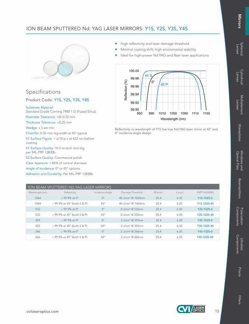
ION BEAM SPUTTERED ND:YAG LASER MIRRORSWavelength (nm) Reflectivity Incidence Angle Damage Threshold Ø (mm) t (mm) PART NUMBER
1064 ≥ 99 9% at 0° 0° 40 J/cm2 @ 1064nm 25 4 6 35 Y1S-1025-0
1064 ≥ 99 9% at 45° (both S & P) 45° 40 J/cm2 @ 1064nm 25 4 6 35 Y1S-1025-45
532 ≥ 99 9% at 0° 0° 8 J/cm2 @ 532nm 25 4 6 35 Y2S-1025-0
532 ≥ 99 9% at 45° (both S & P) 45° 8 J/cm2 @ 532nm 25 4 6 35 Y2S-1025-45
355 ≥ 99 9% at 0° 0° 3 J/cm2 @ 355nm 25 4 6 35 Y3S-1025-0
355 ≥ 99 9% at 45° (both S & P) 45° 3 J/cm2 @ 355nm 25 4 6 35 Y3S-1025-45
266 ≥ 99 9% at 0° 0° 2 J/cm2 @ 266nm 25 4 6 35 Y4S-1025-0
266 ≥ 99 9% at 45° (both S & P) 45° 2 J/cm2 @ 266nm 25 4 6 35 Y4S-1025-45
Reflectivity vs wavelength of Y1S low loss Nd:YAG laser mirror at 45° and 0° incidence angle design
14
Mirro
rs
cvilaseroptics.com
X Applications include: laser marking, precision micromachining, optical tweezers, and Diode-Pumped Solid-State lasers
X Other center wavelengths and substrate dimensions are available for OEM applications
FIBER LASER MIRRORS: FLM
SpecificationsProduct Code: FLM
Substrate Material: Standard Grade Corning 7980 1-D (Fused Silica)
Diameter Tolerance: +0/-0.25mm
Thickness Tolerance: ±0.25mm
Wedge: ≤ 5 arc minutes
Chamfer: 0.35mm leg width at 45° nominal
S1 Surface Figure: < λ/10 p-v at 633nm before coating; after coating on select substrates
S1 Surface Quality: 10-5 scratch-dig per MIL-PRF-13830b (at 100W)
S2 Surface Quality: Commercial polish
Clear Aperture: ≥ 85% of central diameter
Adhesion and Durability: Per MIL-C-48497a
Angle of Incidence: 0° or 45° options
Reflectance: R ≥ 99.0% at 0° R ≥ 98.5% at 45°, P-Pol R ≥ 99.0% at 45°, UNP R ≥ 99.5% at 45°, S-Pol
Damage Threshold: Pulsed: 20 J/cm², 20ns, 20Hz at 1064nm cw:10 MW/cm² at 1064nm
FIBER LASER MIRRORS
Wavelength (nm) Incidence Angle Ø (mm) t (mm) PART NUMBER
343 45 25 4 6 35 FLM-343-1025-45
515 45 25 4 6 35 FLM-515-1025-45
1030 45 12 7 6 35 FLM-1030-0525-45
1030 0 25 4 6 35 FLM-1030-1025-0
1030 45 25 4 6 35 FLM-1030-1025-45
1030 0 50 8 6 35 FLM-1030-2037-0
1030 45 50 8 6 35 FLM-1030-2037-45
1064 0 12 7 6 35 FLM-1064-0525-0
1064 45 12 7 6 35 FLM-1064-0525-45
1064 0 25 4 6 35 FLM-1064-1025-0
1064 45 25 4 6 35 FLM-1064-1025-45
1064 0 50 8 6 35 FLM-1064-2037-0
1064 45 50 8 6 35 FLM-1064-2037-45
1070 45 12 7 6 35 FLM-1070-0525-45
1070 0 25 4 6 35 FLM-1070-1025-0
1070 45 25 4 6 35 FLM-1070-1025-45
1070 0 50 8 6 35 FLM-1070-2037-0
1070 45 50 8 6 35 FLM-1070-2037-45
1550 0 25 4 6 35 FLM-1550-1025-0
1550 45 25 4 6 35 FLM-1550-1025-45
45°P
0°
45°S
950900 1000 1050 1100 1150 12000
20
40
60
80
100
Wavelength (nm)
Ref
lect
ion
(%)
Reflectivity vs wavelength of FLM fiber laser mirror at 1030nm for 0º and 45º designs
Visit cvilaseroptics.com for additional traces

15
Wind
ow
s and
Op
tical FlatsM
irrors
Spherical
LensesC
ylindrical
LensesM
ultielement
LensesW
aveplates
Beam
splitters
Po
larization
Co
mp
onents
Ultrafast
Co
mp
onents
Prism
sFilters
cvilaseroptics.com
Nd:YAG 1064/532nm DUAL WAVELENGTH MIRRORS: HM
HM dielectric wavelength mirrors are designed for high reflectivity and durability at both Nd:YAG and doubled Nd:YAG wavelengths at either 0º or 45º.
X R > 99.0% at 1064nm and 532nm
X Incidence angles other than 0º and 45º may be specified
X Other substrate dimensions are available for OEM capabilities
SpecificationsProduct Code: HM
Substrate Material: Standard Grade Corning 7980 1-D (Fused Silica)
Diameter Tolerance: +0/-0.25mm
Thickness Tolerance: ±0.25mm
Wedge: ≤ 5 arc minutes
Chamfer: 0.35mm leg width at 45° nominal
S1 Surface Figure: < λ/10 p-v at 633nm before coating; after coating on select substrates
S1 Surface Quality: 10-5 scratch-dig per MIL-PRF-13830b (at 100W)
S2 Surface Quality: Commercial polish
Clear Aperture: ≥ 85% of central diameter
Angle of Incidence: 0° or 45° options
Adhesion and Durability: Per MIL-C-48497a
Reflectance:R ≥ 99.0% at 0° at 1064nm and 532nm R ≥ 98.5% at 45°, P-Pol at 1064nm and 532nm
Damage Threshold: 8 J/cm², 20ns, 20Hz at 1064nm 3 J/cm², 10ns, 20Hz at 532nm
Nd:YAG 1064/532nm DUAL WAVELENGTH MIRRORSWavelength
(nm) Incidence
Angle Ø (mm) t (mm) PART NUMBER
1064/532 0° 12 7 6 35 HM-0525-0
1064/532 45° 12 7 6 35 HM-0525-45
1064/532 0° 25 4 6 35 HM-1025-0
1064/532 45° 25 4 6 35 HM-1025-45
1064/532 0° 50 8 9 5 HM-2037-0
1064/532 45° 50 8 9 5 HM-2037-45
450 525 600 675 750 825 900 975 1050 11251200
100
95
90
85
80
75
70
65
60
5550
HM-1025-0
Wavelength (nm)
Tran
smis
sion
(%)
P-POL: UNP: - - - - - S-POL: 0°: - - - - - -

16
Mirro
rs
cvilaseroptics.com
SpecificationsProduct Code: YH
Substrate Material: Standard Grade Corning 7980 1-D (Fused Silica)
Diameter Tolerance: +0/-0.25mm
Thickness Tolerance: ±0.25mm
Wedge: ≤ 5 arc minutes
Chamfer: 0.35mm leg width at 45° nominal
S1 Surface Figure: < λ/10 p-v at 633nm before coating; after coating on select substrates
S1 Surface Quality: 10-5 scratch-dig per MIL-PRF-13830b
S2 Surface Quality: Commercial polish
Clear Aperture: ≥ 85% of central diameter
Angle of Incidence: 45° only
Adhesion and Durability: Per MIL-C-48497a
Reflectance:
R ≥ 99% at 1064nm, R ≥ 80% at 633nm, at 45° UNP
Damage Threshold: >8 J/cm², 20ns, 20Hz at 1064nm
Nd:YAG 1064/633nm DUAL WAVELENGTH MIRRORS: YH
YH dielectric wavelength mirrors are designed for high reflectivity and durability at both Nd:YAG and HeNe wavelengths at either 0º or 45º.
X R > 99% at 1064nm and R > 80% at 633nm
X Alignment mirror for Nd:YAG using HeNe laser
X Contact an applications engineer for OEM options
ND:YAG 1064/633nm DUAL WAVELENGTH MIRRORWavelength
(nm) Incidence
Angle Ø (mm) t (mm) PART NUMBER
1064/633 45° 25 4 6 35 YH-1025-45
1064/633 45° 50 8 9 5 YH-2037-45
P-POL: UNP: - - - - - S-POL: 0°: - - - - - -

17
Wind
ow
s and
Op
tical FlatsM
irrors
Spherical
LensesC
ylindrical
LensesM
ultielement
LensesW
aveplates
Beam
splitters
Po
larization
Co
mp
onents
Ultrafast
Co
mp
onents
Prism
sFilters
cvilaseroptics.com
HIGH POWER TI:SAPPHIRE ULTRAFAST MIRRORS: TLMB
These mirrors are available upon special request for all Ti:Sapphire laser-related center wavelengths.
X Designed for Pulse Lengths > 30 fs
X Broadband design with ultralow group velocity dispersion (GVD)
X High reflectivity: 740 – 860nm for 0º or 45º Unpolarized
Product Code: TLMB
Substrate Material: N-BK7
Diameter Tolerance: +0/-0.25mm
Thickness Tolerance: ±0.25mm
Wedge: ≤ 5 arc minutes
Chamfer: Ø ≤ 50.8mm: 0.35mm leg width at 45° nominal Ø > 50.8mm: 0.85mm leg width at 45° nominal
S1 Surface Figure: < λ/10 p-v at 633nm (after coating)
S1 Surface Quality: 10-5 scratch-dig per MIL-PRF-13830b (at 100W)
S2 Surface Quality: Commercial polish
Clear Aperture: ≥ 85% of central diameter
Angle of Incidence: 0° or 45° options
Center Wavelength: 800nm
Reflectance: R > 99.0% from 740 – 860nm for 0° or 45° UNP
Adhesion and Durability: Per MIL-C-48497a, Insoluble in lab solvents.
Damage Threshold: Pulsed: 0.46 J/cm², 50 fsec, 50Hz at 800nm
A comparison of group delay dispersion vs wavelength of traditional broadband, traditional high laser damage threshold, and the CVI Laser Optics TLMB ultrafast mirror
TLMB-800 Ti:Sapphire broadband mirror showing 0° and 45° angle of incidence designs
BUILD YOUR PART NUMBERSTEP-1 STEP-2 STEP-3 STEP-4
PRODUCT CODE WAVELENGTH ANGLE OF INCIDENCE SIZE CODE
TLMB 800 45 1025
EXAMPLE: TLMB-800-45-1025
CHOOSE FROM THE OPTIONS BELOW.
1. PRODUCT CODE
TLMB
2. WAVELENGTH (nm)
800
3. ANGLE OF INCIDENCE in Degrees
0 0 degrees (normal incidence)
45 45 degrees
4. SIZE CODE DIAMETER (mm) THICKNESS (mm)
2506M 25.0 6.0
1025 25.4 6.35
5010M* 50.0 10.0
2037 50.8 9.53
3050* 76.2 12.7
4050* 101.6 12.7
* Only available at 45° AOI

18
Mirro
rs
cvilaseroptics.com
The TLM2 mirrors are specially designed to achieve high reflectivity and low dispersion for cw oscillators and low-fluence pulses. These mirrors can be coated for any angle of incidence from 0º to 60º and any center wavelength between 450nm and 2100nm for OEM applications. For 45º tuning mirror applications involving very short pulses or very broad bandwidths. Using s - polarization minimizes pulse distortion and maximizes average reflectivity.
TUNABLE BROADBAND MIRRORS: TLM2
SpecificationsProduct Code: TLM2
Substrate Material: N-BK7
Diameter Tolerance: +0/-0.25mm
Thickness Tolerance: ±0.25mm
Wedge: ≤ 5 arc minutes
Chamfer: 0.35mm leg width at 45° nominal
Concentricity: ≤ 0.05mm (spherical substrates only)
Radius Tolerance: ±0.5% (spherical substrates only)
S1 Surface Figure: < λ/10 p-v at 633nm before coating; after coating on select substrates
S1 Surface Quality: 10-5 scratch-dig per MIL-PRF-13830b (at 100W)
S2 Surface Quality: Commercial polish
Adhesion and Durability: Per MIL-C-48497a
Clear Aperture: ≥ 85% of central diameter
Center Wavelength: 800nm, or 1030nm
Reflectance: Please refer to the typical bandwidth tables
Angle of Incidence: 45° only
Damage Threshold: Pulsed: 0.28 J/cm², 50 fsec, 50Hz at 800nm 0.50 J/cm², 20ns, 20Hz at 1064nm
Center Wavelength Tolerance: ±3%
Designed for Pulse Lengths: > 30 fs
0°
45°P
TLM2-800
45°S
700 750 800 850 900 95080
85
90
95
100 Reflectivity vs wavelength of TLM2-800 broadband laser mirror showing 0º and 45º angle of incidence designs
0°
45°P TLM2-800
45°S
700 750 800 850 900 950-100
-50
0
50
100
GD
D (
fs2 )
Group delay dispersion vs wavelength of TLM2-800 broadband laser mirror showing 0º and 45º angle of incidence designs
TYPICAL BANDWIDTH FOR TLM2 MIRRORS
Center Wave-length (nm) R > 99% 0° R > 99.5%° S R > 99% 45° P
800 156 197 76
1030 180 230 80
BUILD YOUR PART NUMBERSTEP-1 STEP-2 STEP-3 STEP-4
PRODUCT CODE WAVELENGTH ANGLE OF INCIDENCE SIZE CODE
TLM2 800 45 1025
EXAMPLE: TLM2-800-45-1025
CHOOSE FROM THE OPTIONS BELOW.
1. PRODUCT CODE
TLM2
2. WAVELENGTH (nm)
800 1030
3. ANGLE OF INCIDENCE in Degrees
45 45 degrees
4. SIZE CODE DIAMETER (mm) THICKNESS (mm)
0525 12.7 6.35
1025 25.4 6.35

19
Wind
ow
s and
Op
tical FlatsM
irrors
Spherical
LensesC
ylindrical
LensesM
ultielement
LensesW
aveplates
Beam
splitters
Po
larization
Co
mp
onents
Ultrafast
Co
mp
onents
Prism
sFilters
cvilaseroptics.com
FLAT MIRRORS WITH MAXBRITE™ BROADBAND COATINGS: MPQ
MAXBRIte™ coatings offer extremely high reflectance over a broad range of wavelengths. Most of the ultraviolet and visible laser wavelengths are covered by one of the two MAXBRIte coating ranges.
X MAXBRIte coatings operate for angles of incidence as high as 45º.
X Minimum of 98% reflectance is achieved over a wide wavelength range at angles of incidence from 0 to 45º.
X Contact CVI Laser Optics for OEM options.
SpecificationsProduct Code: MPQ
Material: Standard Grade Corning 7980 1-D (Fused Silica)
Diameter Tolerance: +0/–0.15mm
Thickness Tolerance: ±0.25mm
Parallelism: ≤ 3 arc minutes
Chamfer: 0.35mm leg width at 45° nominal
S1 Surface Flatness: < λ/4 p-v at 633mm before coating
S1 Surface Quality: 60-40 scratch-dig per MIL-PRF-13830b
Clear Aperture: ≥ 90% of edge dimension or diameter
Average Reflectance: ≥ 98% at 0° – 45° UNP
Damage Threshold: 0.4 J/cm², 10ns at 532 (typical)
MAXBRIte™ coating 245 – 390nm
FLAT MIRRORS WITH MAXBRITE™ BROADBAND COATINGS
UV Broadband Mirror, Round 245 - 390nm
Ø (mm) t (mm) Clear Aperture (mm) PART NUMBER
25 0 6 0 22 5 MPQ-245-390-2506M
Visible Broadband Mirror, Round 420 - 700nm
25 0 6 0 22 5 MPQ-420-700-2506M
MAXBRIte™ coating 420 – 700nm

20
Mirro
rs
cvilaseroptics.com
VACUUM UV ALUMINUM MIRRORS: VUVA
SpecificationsProduct Code: VUVA
Substrate Material: Standard Grade Corning 7980 1-D (Fused Silica)
Diameter Tolerance: +0/-0.25mm
Thickness Tolerance: ±0.25mm
Wedge: ≤ 5 arc minutes
Chamfer: 0.35mm leg width at 45° nominal
S1 Surface Figure: < λ/10 p-v at 633nm
S1 Surface Quality: 40-20 scratch-dig per MIL-PRF-13830b
S2 Surface Quality: Commercial polish
Clear Aperture: ≥ 85% of central diameter
Adhesion and Durability: Per MIL-M-13508c
Reflectance: R > 85% at 157nm by design
Based on CVI Laser Optics high density aluminum coating technology, VUVA mirrors are designed for optimized performance at 157nm. Certification of performance at wavelength is available for an additional charge. Call us for more details.
X Contact an applications engineer for OEM capabilities
VACUUM UV ALUMINUM MIRRORSØ (mm) t (mm) PART NUMBER
25 4 6 35 VUVA-PM-1025-UV
50 8 9 53 VUVA-PM-2037-UV
Theoetical design of VUVA coating at 157nm and 0º

21
Wind
ow
s and
Op
tical FlatsM
irrors
Spherical
LensesC
ylindrical
LensesM
ultielement
LensesW
aveplates
Beam
splitters
Po
larization
Co
mp
onents
Ultrafast
Co
mp
onents
Prism
sFilters
cvilaseroptics.com
DEEP UV ALUMINUM MIRRORS: DUVA
SpecificationsProduct Code: DUVA
Substrate Material: Standard Grade Corning 7980 1-D (Fused Silica)
Diameter Tolerance: +0/-0.25mm
Thickness Tolerance: ±0.25mm
Wedge: ≤ 5 arc minutes
Chamfer: 0.35mm leg width at 45° nominal
S1 Surface Figure: < λ/10 p-v at 633nm
S1 Surface Quality: 40-20 scratch-dig per MIL-PRF-13830b
S2 Surface Quality: Commercial polish
Clear Aperture: ≥ 85% of central diameter
Adhesion and Durability: Per MIL-M-13508c
Reflectance: R > 90% at 193nm, Ravg ≥ 85% at 400 – 1200nm
Based on CVI Laser Optics high-density aluminum coating technology, broadband DUVA mirrors provide significantly higher 193nm reflectance and durability than standard UV-protected aluminum mirrors. Choose semi-custom or standard optics for your ellipsometry, spectroscopy, and semiconductor lithography or metrology applications.
X Contact an applications engineer for OEM capabilities
DEEP UV ALUMINUM MIRRORSØ (mm) t (mm) PART NUMBER
12 7 3 18 DUVA-PM-0512-UV
25 4 6 35 DUVA-PM-1025-UV
50 8 9 53 DUVA-PM-2037-UV
185
100
96
Typical reflection curve
250
88
200 230
92
84
220 240210190
normal incidence
Reflection vs wavelength of 193nm deep UV aluminum coating at 0º

22
Mirro
rs
cvilaseroptics.com
UV ENHANCED ALUMINUM FLAT MIRRORS: PAUV
SpecificationsProduct Code: PAUV
Substrate Material: N-BK7
Dimensional Tolerances: Square: +0/–0.25m Round: +0/–0.25mm
Thickness Tolerance: ±0.25mm
Parallelism: ≤ 5 arc minutes
Chamfer: Ø ≤ 50.8mm: 0.35mm leg width at 45° nominal Ø > 50.8mm: 0.85mm leg width at 45° nominal
S1 Surface Figure: < λ/10 p-v at 633nm on select substrates (see table)
S1 Surface Quality: 40-20 scratch-dig per MIL-PRF-13830b
S2 Surface Quality: Commercial polish
Clear Aperture: 90% of edge dimension or diameter (85% for PAUV-PM series)
Coating: UV-enhanced aluminum
Average Reflectance: ≥ 85% at 250 – 600nm
UV enhanced aluminum mirrors have an additional dielectric coating that prevents oxidation and preserves the reflectance of bare aluminum in the ultraviolet.
X Average reflectance is greater than 86% from 250 to 600nm
X Contact an applications engineer for OEM capabilities
200
7075
80
85
90
95
100
300 400 500 600 700 800 900 1000
Wavelength (nm)
Ref
lect
ion
(%)
Typical reflection curves
UV enhanced aluminum coating at 0°
UV ENHANCED ALUMINUM FLAT MIRRORS
Shape Ø (mm) □ (mm) t (mm) Clear Aperture (mm) Surface Figure (S1) PART NUMBER
Round 12 7 — 6 35 11 3 < λ/10 PAUV-PM-0525-C
Round 25 4 — 6 35 21 6 < λ/10 PAUV-PM-1025-C
Square — 25 4 6 35 22 5x22 5 < λ/4 PAUV-SQM-1025-C
Round 50 8 — 10 0 45 0 < λ/10 PAUV-PM-2037-C
Square — 50 8 9 53 45 0x45 0 < λ/4 PAUV-SQM-2037-C
Round 76 2 — 12 7 64 8 < λ/10 PAUV-PM-3050-C

23
Wind
ow
s and
Op
tical FlatsM
irrors
Spherical
LensesC
ylindrical
LensesM
ultielement
LensesW
aveplates
Beam
splitters
Po
larization
Co
mp
onents
Ultrafast
Co
mp
onents
Prism
sFilters
cvilaseroptics.com
SpecificationsProduct Code: PAV
Substrate Material: N-BK7
Dimensional Tolerances: Square: +0/–0.25mm Round: +0/–0.25mm
Thickness Tolerance: ±0.25mm
Parallelism: ≤ 5 arc minutes
Chamfer: Ø ≤ 50.8mm: 0.35mm leg width at 45° nominal Ø > 50.8mm: 0.85mm leg width at 45° nominal
S1 Surface Figure: < λ/10 p-v at 633nm on select substrates
S1 Surface Quality: 40-20 scratch-dig per MIL-PRF-13830b
S2 Surface Quality: Commercial polish
Clear Aperture: Round: ≥ 85% of central diameter Square: ≥ 90% of edge dimension
Coating: Protected aluminum
Average Reflectance: ≥ 87% at 400 – 800nm
PROTECTED ALUMINUM FLAT MIRRORS: PAV
Protected aluminum is the best general-purpose metallic coating for external reflectors in the visible and near-infrared spectrum.
X Average reflectance greater than 87% from 400 to 800nm
X Contact an applications engineer for OEM capabilities
PROTECTED ALUMINUM FLAT MIRRORS
Shape Ø (mm) □ (mm) t (mm) Clear Aperture (mm) Surface Figure (S1) PART NUMBER
Round 12 7 — 6 35 10 8 < λ/10 PAV-PM-0525-C
Round 25 4 — 6 35 21 6 < λ /10 PAV-PM-1025-C
Square — 25 4 6 35 22 5x22 5 < λ/4 PAV-SQM-1025-C
Round 50 8 — 9 53 43 2 < λ/10 PAV-PM-2037-C
Square — 50 8 9 53 45 0x45 0 < λ/4 PAV-SQM-2037-C
Round 76 2 — 12 7 64 8 < λ/10 PAV-PM-3050-C
Protected aluminum coating

24
Mirro
rs
cvilaseroptics.com
ENHANCED ALUMINUM FLAT MIRRORS: EAV
SpecificationsProduct Code: EAV
Substrate Material: N-BK7
Diameter: +0/–0.25mm
Thickness Tolerance: ±0.25mm
Parallelism: ≤ 5 arc minutes
Chamfer: Ø ≤ 50.8mm: 0.35mm leg width at 45° nominal Ø > 50.8mm: 0.85mm leg width at 45° nominal
S1 Surface Figure: < λ/10 p-v at 633nm
S1 Surface Quality: 40-20 scratch-dig per MIL-PRF-13830b
S2 Surface Quality: Commercial polish
Clear Aperture: ≥ 85% of central diameter
Coating: Enhanced aluminum
Average Reflectance: ≥ 92% at 450–650nm
Enhanced aluminum is an aluminum coating overcoated with a durable multi-layer dielectric film which both increases reflectance throughout the visible spectrum and provides protection from the environment and handling.
X Peak reflectance is 95% with average reflectance across the visible spectrum of 92%
Enhanced aluminum coating
ENHANCED ALUMINUM FLAT MIRRORS
Ø (mm) t (mm) Clear Aperture (mm) PART NUMBER
12 7 6 35 11 3 EAV-PM-0525-C
25 4 6 35 22 5 EAV-PM-1025-C
50 8 9 53 45 0 EAV-PM-2037-C
76 2 12 7 67 5 EAV-PM-3050-C

25
Wind
ow
s and
Op
tical FlatsM
irrors
Spherical
LensesC
ylindrical
LensesM
ultielement
LensesW
aveplates
Beam
splitters
Po
larization
Co
mp
onents
Ultrafast
Co
mp
onents
Prism
sFilters
cvilaseroptics.com
SpecificationsProduct Code: PS
Substrate Material: N-BK7
Dimensional Tolerances: Square: +0/–0.25mm
Round: +0/–0.25mm
Thickness Tolerance: ±0.25mm
Parallelism: ≤ 5 arc minutes
Chamfer: Ø ≤ 50.8mm: 0.35mm leg width at 45° nominal Ø > 50.8mm: 0.85mm leg width at 45° nominal
S1 Surface Figure: < λ/10 p-v at 633nm on select substrates
S1 Surface Quality: 40-20 scratch-dig per MIL-PRF-13830b
S2 Surface Quality: Commercial polish
Clear Aperture: Round: ≥ 85% of central diameter Square: ≥ 80% of edge dimension
Coating: Protected silver
Average Reflectance: ≥ 95% at 400nm to 20µm
PROTECTED SILVER FLAT MIRRORS: PS
X Protected silver has higher reflectance than aluminum throughout the visible and near-infrared spectral region
X Minimal pulse distortion for ultrafast Ti:Sapphire lasers
X A proprietary overcoat provides increased durability
X CVI Laser Optics suggests using the drag and drop method with acetone for the cleaning of these mirrors.
X Contact an applications engineer for OEM capabilities
PROTECTED SILVER FLAT MIRRORS
Shape Ø (mm) □ (mm) t (mm) Min. Clear Aperture (mm) Surface Figure (S1) PART NUMBER
Round 12 7 — 6 35 10 8 < λ/10 PS-PM-0525-C
Round 25 4 — 6 35 21 6 < λ/10 PS-PM-1025-C
Square — 25 4 6 35 22 5x22 5 < λ/4 PS-SQM-1025-C
Round 50 8 — 9 53 43 2 < λ/10 PS-PM-2037-C
Square — 50 8 9 53 45 0x45 0 < λ/4 PS-SQM-2037-C
Round 76 2 — 12 7 64 8 < λ/10 PS-PM-3050-C
Protected silver coating at 0º

26
Mirro
rs
cvilaseroptics.com
PROTECTED GOLD FLAT MIRRORS: PG
SpecificationsProduct Code: PG
Substrate Material: N-BK7
Dimensional Tolerances: Square: +0/–0.25mm Round: +0/–0.25mm
Thickness Tolerance: ±0.25mm
Parallelism: ≤ 5 arc minutes
Chamfer: Ø ≤ 50.8mm: 0.35mm leg width at 45° nominal Ø > 50.8mm: 0.85mm leg width at 45° nominal
S1 Surface Figure: < λ/10 p-v at 633nm on select substrates
S1 Surface Quality: 40-20 scratch-dig per MIL-PRF-13830b
S2 Surface Quality: Commercial polish
Clear Aperture: Square: ≥ 80% of edge dimension Round: ≥ 85% of central diameter
Coating: Protected gold
Average Reflectance: ≥ 95.5% at 650 – 1700nm, ≥ 98.0% at 2 – 20μm
X Protected gold combines the natural spectral performance of gold with the enhanced protection of a durable dielectric overcoat
X Protected gold provides 95.5% average reflectance from 650 to 1700nm, and over 98% average reflectance from 2 to 20 µm
X Contact an applications engineer for OEM capabilities and/or bare gold coatings
Protected gold coating at 0º
PROTECTED GOLD FLAT MIRRORS
Shape Ø (mm) □ (mm) t (mm) Clear Aperture (mm) Surface Figure (S1) PART NUMBER
Round 12 7 — 6 35 10 8 < λ/10 PG-PM-0525-C
Round 25 4 — 6 35 21 6 < λ/10 PG-PM-1025-C
Round 50 8 — 9 53 43 2 < λ/10 PG-PM-2037-C
Round 76 2 — 12 7 64 8 < λ/10 PG-PM-3050-C

27
Wind
ow
s and
Op
tical FlatsM
irrors
Spherical
LensesC
ylindrical
LensesM
ultielement
LensesW
aveplates
Beam
splitters
Po
larization
Co
mp
onents
Ultrafast
Co
mp
onents
Prism
sFilters
cvilaseroptics.com
The fused silica plano-convex mirror substrates are polished to a 10-5, λ/10 surface on both sides, so they can be used as high reflectors, dichroic mirrors, or partial reflecting output couplers.
X All CVI Laser Optics high reflector, metal, and partial reflector coatings available
X Mirror focal length = –r/2
X Other dimensions and radii available in prototype and production quantities
X Tighter radius tolerance available
CONVEX SPHERICAL FUSED SILICA MIRROR BLANKS: SMCX-UV
SpecificationsProduct Code: SMCX-UV
Substrate Material: Standard Grade Corning 7980 1-D (Fused Silica)
Diameter Tolerance: +0/-0.25mm
Thickness Tolerance: ±0.25mm
Chamfer: 0.35mm leg width at 45° nominal
Concentricity: < 0.05mm
Radius Tolerance: ±0.5%
S1 Surface Figure: < λ/10 p-v at 633nm
S1 Surface Quality: 10-5 scratch-dig per MIL-PRF-13830b (at 100W)
S2 Surface Figure: < λ/10 p-v at 633nm
S2 Surface Quality: 10-5 scratch-dig per MIL-PRF-13830b (at 100W)
Clear Aperture: ≥ 85% of central diameterCONVEX FUSED SILICA SPHERICAL MIRROR BLANKS
Ø (mm) t (mm) r (m) PART NUMBER
12 7 6 35 1 00 SMCX-0525-1.00-UV
25 4 6 35 0 30 SMCX-1025-0.30-UV
25 4 6 35 0 50 SMCX-1025-0.50-UV
25 4 6 35 1 00 SMCX-1025-1.00-UV
T
D
Convex spherical mirror blank

28
Mirro
rs
cvilaseroptics.com
SpecificationsProduct Code: SMCC-C, SMCC-UV
Substrate Material: N-BK7 or Standard Grade Corning 7980 1-D (Fused Silica)
Diameter Tolerance: +0/-0.25mm
Thickness Tolerance: ±0.25mm
Concentricity: < 0.05mm
Radius Tolerance: ±0.5% for r ≤ 3.5 m ±1.0% for r > 3.5 m
S1 Surface Figure: < λ/10 p-v at 633nm
S1 Surface Quality: 10-5 scratch-dig per MIL-PRF-13830b (at 100W)
S2 Surface Figure: < λ/10 p-v at 633nm
S2 Surface Quality: 10-5 scratch-dig per MIL-PRF-13830b (at 100W)
Clear Aperture: ≥ 85% of central diameter
CONCAVE SPHERICAL FUSED SILICA / N-BK7 MIRROR BLANKS: SMCC-C, SMCC-UV
T
f
Concave spherical mirror blank
CONCAVE SPHERICAL MIRROR BLANKS:Standard Grade Corning 7980 1-D (Fused Silica)
Ø (mm) t (mm) r (m) PART NUMBER
12 7 6 35 0 025 SMCC-0525-0.025-UV
12 7 6 35 0 050 SMCC-0525-0.050-UV
12 7 6 35 0 075 SMCC-0525-0.075-UV
12 7 6 35 0 10 SMCC-0525-0.10-UV
12 7 6 35 0 15 SMCC-0525-0.15-UV
12 7 6 35 0 20 SMCC-0525-0.20-UV
12 7 6 35 0 25 SMCC-0525-0.25-UV
12 7 6 35 0 50 SMCC-0525-0.50-UV
12 7 6 35 1 00 SMCC-0525-1.00-UV
12 7 6 35 1 50 SMCC-0525-1.50-UV
12 7 6 35 5 00 SMCC-0525-5.00-UV
25 4 6 35 0 025 SMCC-1025-0.025-UV
25 4 6 35 0 050 SMCC-1025-0.050-UV
25 4 6 35 0 10 SMCC-1025-0.10-UV
25 4 6 35 0 15 SMCC-1025-0.15-UV
25 4 6 35 0 20 SMCC-1025-0.20-UV
25 4 6 35 0 25 SMCC-1025-0.25-UV
25 4 6 35 0 30 SMCC-1025-0.30-UV
25 4 6 35 0 50 SMCC-1025-0.50-UV
25 4 6 35 0 75 SMCC-1025-0.75-UV
25 4 6 35 1 00 SMCC-1025-1.00-UV
25 4 6 35 1 50 SMCC-1025-1.50-UV
25 4 6 35 2 00 SMCC-1025-2.00-UV
25 4 6 35 3 00 SMCC-1025-3.00-UV
25 4 6 35 5 00 SMCC-1025-5.00-UV
25 4 6 35 10 0 SMCC-1025-10.0-UV
50 8 9 53 0 50 SMCC-2037-0.50-UV
50 8 9 53 1 00 SMCC-2037-1.00-UV
50 8 9 53 1 50 SMCC-2037-1.50-UV
50 8 9 53 2 00 SMCC-2037-2.00-UV
N-BK7
Ø (mm) t (mm) r (m) PART NUMBER
12 7 6 35 0 25 SMCC-0525-0.25-C
12 7 6 35 0 50 SMCC-0525-0.50-C
12 7 6 35 1 00 SMCC-0525-1.00-C
25 4 6 35 0 25 SMCC-1025-0.25-C
25 4 6 35 0 50 SMCC-1025-0.50-C
25 4 6 35 1 00 SMCC-1025-1.00-C

29
Wind
ow
s and
Op
tical FlatsM
irrors
Spherical
LensesC
ylindrical
LensesM
ultielement
LensesW
aveplates
Beam
splitters
Po
larization
Co
mp
onents
Ultrafast
Co
mp
onents
Prism
sFilters
cvilaseroptics.com
X All CVI Laser Optics partial reflectors, high reflectors, dichroics and metal coatings available.
X Other dimensions or materials available in production and prototype quantities
PLANE ROUND FUSED SILICA / N-BK7 MIRROR BLANKS: PM-UV, PM-C
SpecificationsProduct Code: PM-UV, PM-C
Substrate Material: N-BK7 or Standard Grade Corning 7980 1-D (Fused Silica)
Dimensional Tolerance: +0/-0.25mm
Thickness Tolerance: ±0.25mm
Wedge: ≤ 5 arc minutes
Chamfer: Ø ≤ 50.8mm: 0.35mm leg width at 45° nominal Ø > 50.8mm: 0.85mm leg width at 45° nominal
S1 Surface Figure: per table; measured p-v at 633mm
S1 Surface Quality: 10-5 scratch-dig per MIL-PRF-13830b (at 100W)
S2 Surface Quality: Commercial polish
Clear Aperture: ≥ 85% of central diameter
PLANE ROUND MIRROR BLANKSStandard Grade Corning 7980 1-D (Fused Silica)
Ø (mm) t (mm) S1 Surface Figure PART NUMBER
12 7 6 35 < λ/10 PM-0525-UV
19 1 6 35 < λ/10 PM-0725-UV
25 0 6 0 < λ/10 PM-2506M-UV
25 4 3 18 < λ/4 PM-1012-UV
25 4 6 35 < λ/10 PM-1025-UV
25 4 9 53 < λ/10 PM-1037-UV
38 1 6 35 < λ/10 PM-1525-UV
50 0 10 0 < λ/10 PM-5010M-UV
50 8 6 35 < λ/10 PM-2025-UV
50 8 9 53 < λ/10 PM-2037-UV
76 2 12 7 < λ/10 PM-3050-UV
101 6 9 53 < λ/10 PM-4037-UV
101 6 12 7 < λ/10 PM-4050-UV
152 4 25 4 < λ/10 PM-6010-UV
N-BK7
Ø (mm) t (mm) S1 Surface Figure PART NUMBER
12 7 3 18 < λ/10 PM-0512-C
12 7 6 35 < λ/10 PM-0525-C
25 0 6 0 < λ/10 PM-2506M-C
25 4 3 18 < λ/4 PM-1012-C
25 4 6 35 < λ/10 PM-1025-C
50 8 6 35 < λ/4 PM-2025-C
76 2 12 7 < λ/10 PM-3050-C
NOTE: See PW1-UV for additional options (page 94)
f
T
S2S1
Plane round mirror blank

30
Mirro
rs
cvilaseroptics.com
PLANE SQUARE FUSED SILICA / N-BK7 MIRROR BLANKS: SQM-C, SQM-UV
SpecificationsProduct Code: SQM-C, SQM-UV
Substrate Material: N-BK7 or Standard Grade Corning 7980 1-D (Fused Silica)
Dimensional Tolerance: +0/-0.25mm
Thickness Tolerance: ±0.25mm
Wedge: ≤ 5 arc minutes
Chamfer: 0.35mm leg width at 45° nominal
S1 Surface Figure: See table (measured p-v at 633nm)
S1 Surface Quality: 10-5 scratch-dig per MIL-PRF-13830b (at 100W)
S2 Surface Quality: Commercial polish
Clear Aperture: ≥ 85% of central diameterPLANE SQUARE MIRROR BLANKSStandard Grade Corning 7980 1-D (Fused Silica)
l (mm) t (mm) S1 Surface Figure PART NUMBER
25 4 6 35 < λ/10 SQM-1025-UV
50 8 9 53 < λ/10 SQM-2037-UV
N-BK7
l (mm) t (mm) S1 Surface Figure PART NUMBER
25 4 6 35 < λ/4 SQM-1025-C
50 8 9 53 < λ/4 SQM-2037-C
L
L
T
S1 S2
Plane square mirror blank
X Available in N-BK7 and Standard Grade Corning 7980 1-D (Fused Silica)
X All CVI Laser Optics high reflector, partials, dichroics and metal coatings available
X Other dimensions available in production and prototype quantities

31
Wind
ow
s and
Op
tical FlatsM
irrors
Spherical
LensesC
ylindrical
LensesM
ultielement
LensesW
aveplates
Beam
splitters
Po
larization
Co
mp
onents
Ultrafast
Co
mp
onents
Prism
sFilters
cvilaseroptics.com
PLANE RECTANGULAR FUSED SILICA MIRROR BLANKS: RM-UV
SpecificationsProduct Code: RM-UV
Substrate Material: Standard Grade Corning 7980 1-D (Fused Silica)
Dimensional Tolerance: +0/-0.25mm
Thickness Tolerance: ±0.25mm
Wedge: ≤ 5 arc minutes
Chamfer: 0.35mm leg width at 45° nominal
S1 Surface Figure: < λ/4 p-v at 633nm
S1 Surface Quality: 10-5 scratch-dig per MIL-PRF-13830b (at 100W)
S2 Surface Quality: Commercial polish
Clear Aperture: ≥ 85% of central diameter PLANE RECTANGULAR FUSED SILICA MIRROR BLANKSl (mm) w (mm) t (mm) PART NUMBER
20 10 6 35 RM-20.0-10.0-6.35-UV
35 20 9 53 RM-35.0-20.0-9.53-UV
40 25 9 53 RM-40.0-25.0-9.53-UV
50 30 12 7 RM-50.0-30.0-12.7-UV
L T
W
S1 S2
Plane rectangular mirror blank
X Available in Standard Grade Corning 7980 1-D (Fused Silica)
X All CVI Laser Optics high reflector, partials, dichroics and metal coatings available
X Other dimensions available in production and prototype quantities

Spherical Lenses
32 cvilaseroptics.com
PV: The difference between the lowest point and the highest point of the optical surface.
RMS: The measurement of the clear aperture of the optical surface, then calculating the standard deviation (taking the square root of all values and squaring them).
• The average PV vs RMS ratio for the combination of: Focus, Astigmatism, Coma and
Spherical Aberration, is 3-5:1
• CVI Laser Optics specifies the PV error given the fact that our polishing process is such
that our RMS values are significantly below λ/50 for our laser grade optics.
• CVI Laser Optics average surface roughness is between 3-5Å for laser grade optics
Surface Figure: Peak to Valley (PV) vs Root Mean Squared (RMS)
Consistent High Quality by a brand you can trust!
PV: < λ/20RMS: < λ/111Laser Grade
PV: < λ/10RMS: < λ/62Laser Grade
PV: < λ/4RMS: < λ/22Image Grade


