Solutions for Today | Options for Tomorrow
MFiX Simulations of Gas-Solid Flow in Large Scale Fluidized Bed Reactors
June 21, 2017, IFPRI AGM Tingwen Li, Ph.D. P.E. AECOM/NETL

2
• Introduction on Fluidization and MFiX • Two-fluid model simulation of coal gasification process • Efforts to speedup discrete particle simulations • Concluding remarks
Outline
3
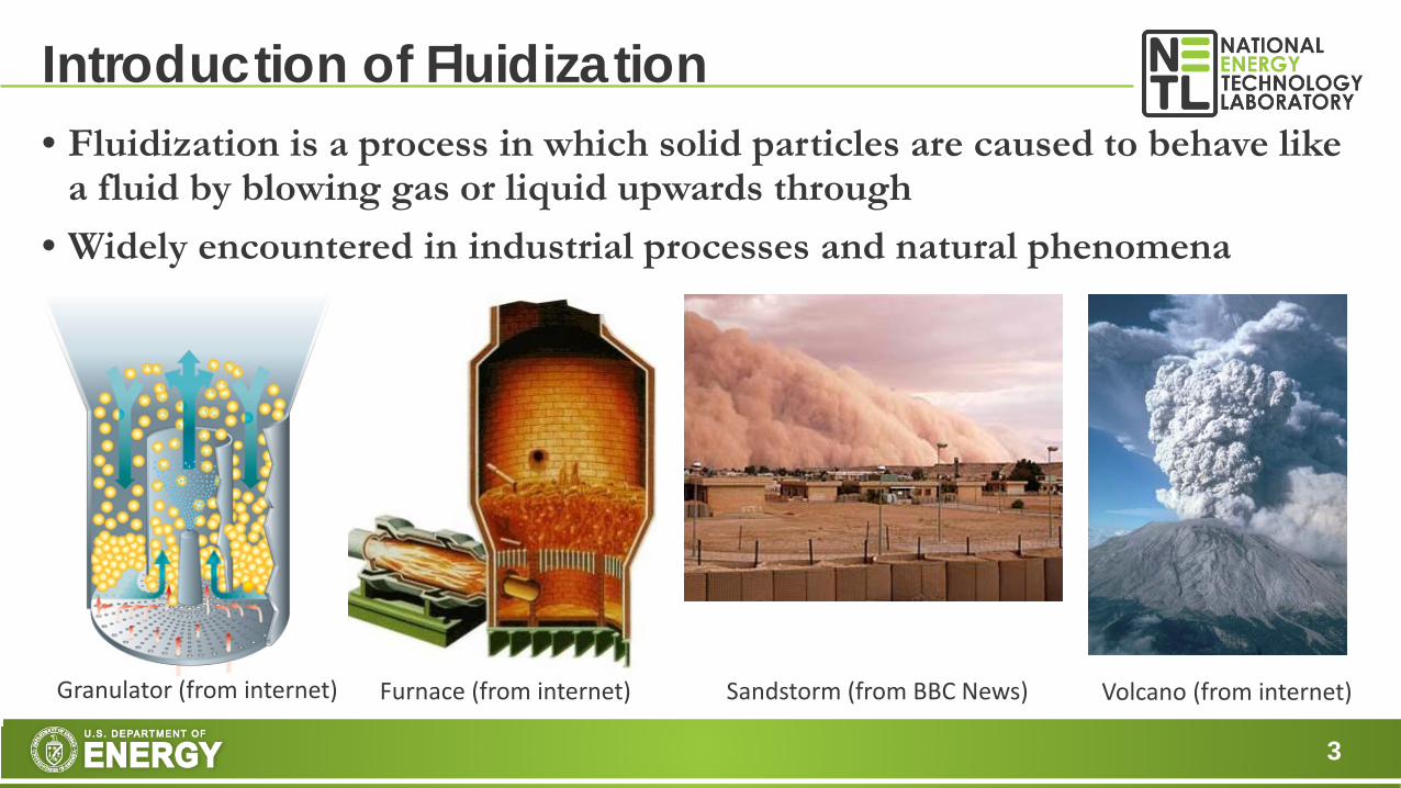
• Fluidization is a process in which solid particles are caused to behave like a fluid by blowing gas or liquid upwards through
• Widely encountered in industrial processes and natural phenomena
Introduction of Fluidization
Sandstorm (from BBC News) Volcano (from internet) Furnace (from internet) Granulator (from internet)
4
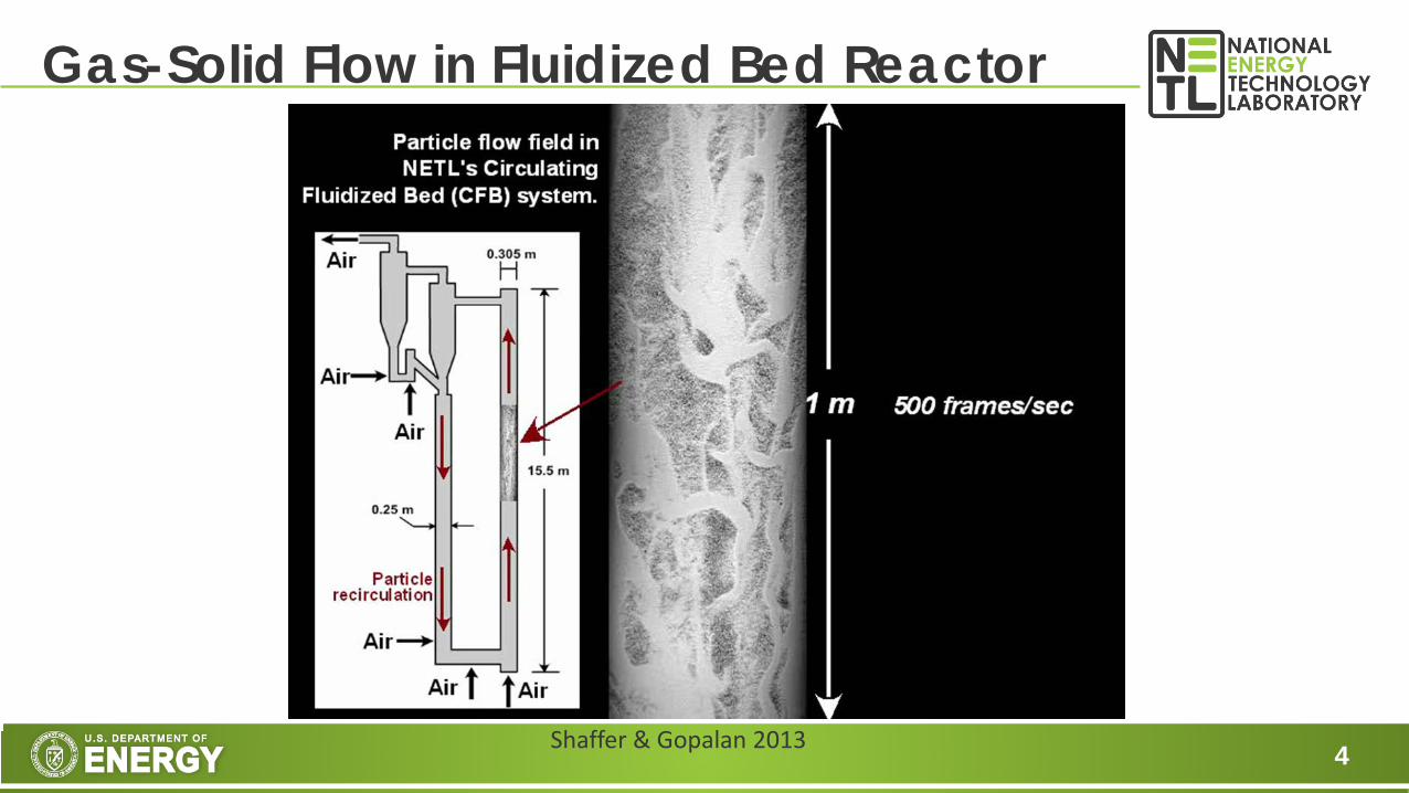
Gas-Solid Flow in Fluidized Bed Reactor
Shaffer & Gopalan 2013

5
Gas-Solid Flow in Fluidized Bed Reactor
Shaffer & Gopalan 2013
6
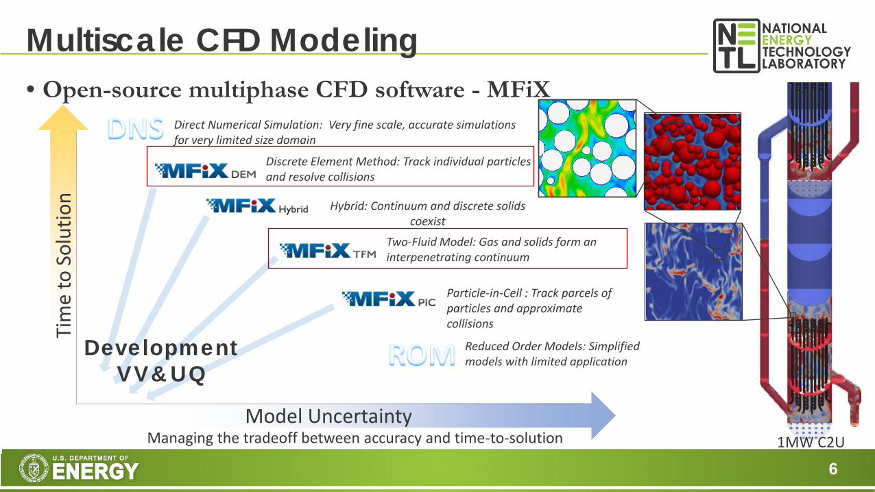
• Open-source multiphase CFD software - MFiX
Multiscale CFD Modeling
Model Uncertainty
Tim
e to
Sol
utio
n
Discrete Element Method: Track individual particles and resolve collisions
Two-Fluid Model: Gas and solids form an interpenetrating continuum
Particle-in-Cell : Track parcels of particles and approximate collisions
Hybrid: Continuum and discrete solids coexist
Direct Numerical Simulation: Very fine scale, accurate simulations for very limited size domain
Reduced Order Models: Simplified models with limited application
Development VV&UQ
Managing the tradeoff between accuracy and time-to-solution 1MW C2U

Two-Fluid Model Simulation of Gasification

8
• Solid fuels to syngas • Applicable to a variety of feedstocks, high conversion efficiency, low environmental impact
Gasification
NETL Gasifipedia
CO CO2H2

9
• Transport integrated gasification (TRIG) • Developed by KBR, Southern, and DOE based on KBR
FCC technology • Can be operated in air- and oxygen-blown with high
through-put and flexibility • Well suited for low-rank coal with high moisture and ash
contents • Demonstrated by Power Systems Development Facility
• State-of-the-art test center sponsored by DOE • Dedicated to advancement of clean coal technology • Features key components of an IGCC system
• Commercialized by Kemper Project • $7.2B project at Kemper County in Mississippi • First-of-its-kind cleantech power plant • 582MW power from Mississippi lignite with 65% CO2 capture
TRIGTM
TRIGTM Schematic www.kbr.com

10
• Use PSDF data to validate NETL CFD models and chemical kinetic tools for TRIG using Mississippi lignite fuel
• Prepare the modeling tools to support gasifier designers and operators for Kemper project
• Provide insight to guide the continued development and validation of computational tools
Objectives

11
• Detailed setup • 3D cut-cell with all inlets/outlets resolved • Fine grid of 1.3M computational cells • Two solid phases for coal and recycled matter • Computationally expensive
• Simplified setup • Only resolved major inlets and outlets • Point sources near wall for small feed streams • Coarse grid of 400K computational cells • Lump all solids into one phase • Filtered models developed at Princeton for
momentum, heat and mass transfer to capture subgrid-scale physics
• Less expensive but retains major flow features
Model Setup
air & steam
recycled char & ash
air coal
nitrogen air
13MW PSDF Gasifier

12
• C3M* • Carbonaceous Chemistry for Computational
Modeling • Seamless connection between CFD software
and chemical kinetic packages • Analysis on chemical kinetics with uncertainty
quantification • Chemical kinetics
• Detailed gasification kinetics for Mississippi Lignite coal from PC Coal Lab through C3M. • 17 gas species & 4 solid pseudo-species with thermodynamic properties provided by C3M
with 13 chemical reactions solved. • Surrogate model for gasification reaction rate covering a wide range of local conditions.
• All reaction kinetics handled by C3M • Same kinetics for all simulations without any ‘tweaking’ (Li et al.2016)
Gasification Kinetics
Architecture of C3M (Li et al. 2013)
MGAS CPD DATA FG-DVC PCCL
C3M
MFiX FLUENT
Process Model
Stand Alone Mode
CPFD
* More information on https://mfix.netl.doe.gov/c3m

13
• Operating conditions for PSDF gasifier • 11 test runs using Mississippi Lignite (TC25, 2008) • Temperature controlled by air feeding (~1600-1750F) • Reactor pressure (~191-211 psig) • Coal feed rate (~3500-4340 lb/hr) • Steam-to-coal ratio (~0.005-0.174) • As-fed lignite coal composition (after drying)
Simulation Conditions
Proximate analysis Ultimate analysis
Fixed carbon (%) 31 Carbon (%) 46
Volatile matter (%) 37.1 Hydrogen (%) 3.5
Moisture (%) 17.1 Oxygen (%) 17.1
Ash (%) 14.8 Nitrogen (%) 1
Sulphur (%) 0.6
Distribution of Tg, Cco, Ch2o and Vofs

14
Simulation Results
LMZ
• Comparison of pressure drop and temperature

15
Simulation Results • Syngas composition at exit
Measured Predicted
Predicted exit syngas compositions are in good agreement with measurements - with most discrepancies within 20%.

16
• MFiX-TFM simulations with filtered subgrid models predict PSDF transport gasifier reasonably well for Mississippi lignite
• Use of PC Coal Lab database through C3M software provides accurate gasification kinetics
• NETL numerical model and chemical kinetic tools are validated and ready for Kemper project
Summary

Speedup of discrete particle simulations

18
• MFiX-DEM • Superior modeling capability • Systematic VV & UQ • Parallel computation: MPI + SMP • High computational cost
• MFiX-PIC • High computational speed • Lack of rigorous validations
• Recent efforts on speedup • Time-driven hard-sphere model • Coarse-grain particle method • MFiX-EXA (ongoing!)
Discrete particle models in MFiX
Speed
Accuracy
DEM
PIC
Small ∆t, large particle count
HS CG DEM CG
HS
Particle Parcel Big increase in Speed Little lost in Accuracy
Large ∆t, small particle count

19
• Time-driven hard-sphere • Larger time step with speedup by a factor of 10~20 comparing to soft-sphere model • Novel velocity correction to solve over-packing issue for dense flow (Lu et al. 2017) • TDHS has been verified and validated for different flow problems of interest
Hard-Sphere Model
Soft-sphere Stand hard-sphere Hard-sphere-corrected
Agitated granular assembly settle in a box

20
• Time-driven hard-sphere • Larger time step with speedup by a factor of 10~20 comparing to soft-sphere model • Novel velocity correction to solve over-packing issue for dense flow (Lu et al. 2017) • TDHS has been verified and validated for different flow problems of interest
Hard-Sphere Model
Agitated granular assembly settle in a box
Soft-sphere Stand hard-sphere Hard-sphere-corrected

21
• Overview • Represent a group of particles using a large coarse-grain
numerical particle • Reduce particle count and increase solid time step • Accuracy is compromised but controllable
• Strategies for scaling of CG-DEM • Force scaling for linear spring-dashpot model
• (Sakai et al. 2009, Benyahia & Galvin 2010 ) • (Radl et al. 2011, Thakur et al. 2016) • (Lu et al. 2014)
• Energy dissipation • (Benyahia & Galvin 2010) • (Lu et al. 2014) • Relaxation of particle velocity (Radl et al. 2011)
Coarse-Grain DEM
Schematic from Sakai et al. 2012
3,n CG nk l k=
,n CG nk lk=
,n CG nk k=
( ) ( )1 321 1 1CG p CGPe e l ε= + − −
( ) ( ) 3 2ln lnCG pe e l≈
3 1l →

22
CG-DEM for Heat Transfer
Mean temperature profiles by different methods Particle temperature simulated with different methods
• Extension of coarse-grain DEM to heat transfer in fluidized beds (Lu et al. 2017)
MFiX-DEM CG-DEM-2 CG-DEM-3
CG-DEM-3 CG-DEM-2 MFiX-DEM

23
• PFB @ UCL • Pseudo-2D bed with 65M glass beads • Pulsating air flow through distributor • Structured alternative bubble pattern • A good benchmark for CFD models • TFM & PIC failed to capture the pattern
Pulsed Fluidized Bed
Experiment at UCL by Coppens’ group CG-DEM simulation using 8M parcels

24
• Particle segregation in vortex chamber • Systematic study on effect of particle size and density ratios (Verma et al. 2017)
Rotating Fluidized Bed
Rotating fluidized bed in vortex chamber (De Wilde et al. 2016)

25
• Particle segregation in vortex chamber • Systematic study on effect of particle size and density ratios (Verma et al. 2017)
Rotating Fluidized Bed
Standard MFiX-DEM Coarse-Grain DEM
Verification of coarse-grain MFIX-DEM simulation

26
27
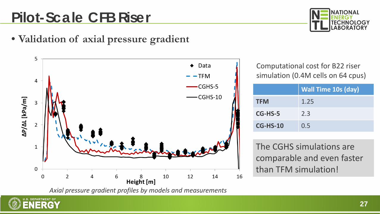
• Validation of axial pressure gradient
Pilot-Scale CFB Riser
Wall Time 10s (day)
TFM 1.25
CG-HS-5 2.3
CG-HS-10 0.5
Computational cost for B22 riser simulation (0.4M cells on 64 cpus)
Axial pressure gradient profiles by models and measurements
The CGHS simulations are comparable and even faster than TFM simulation!
28
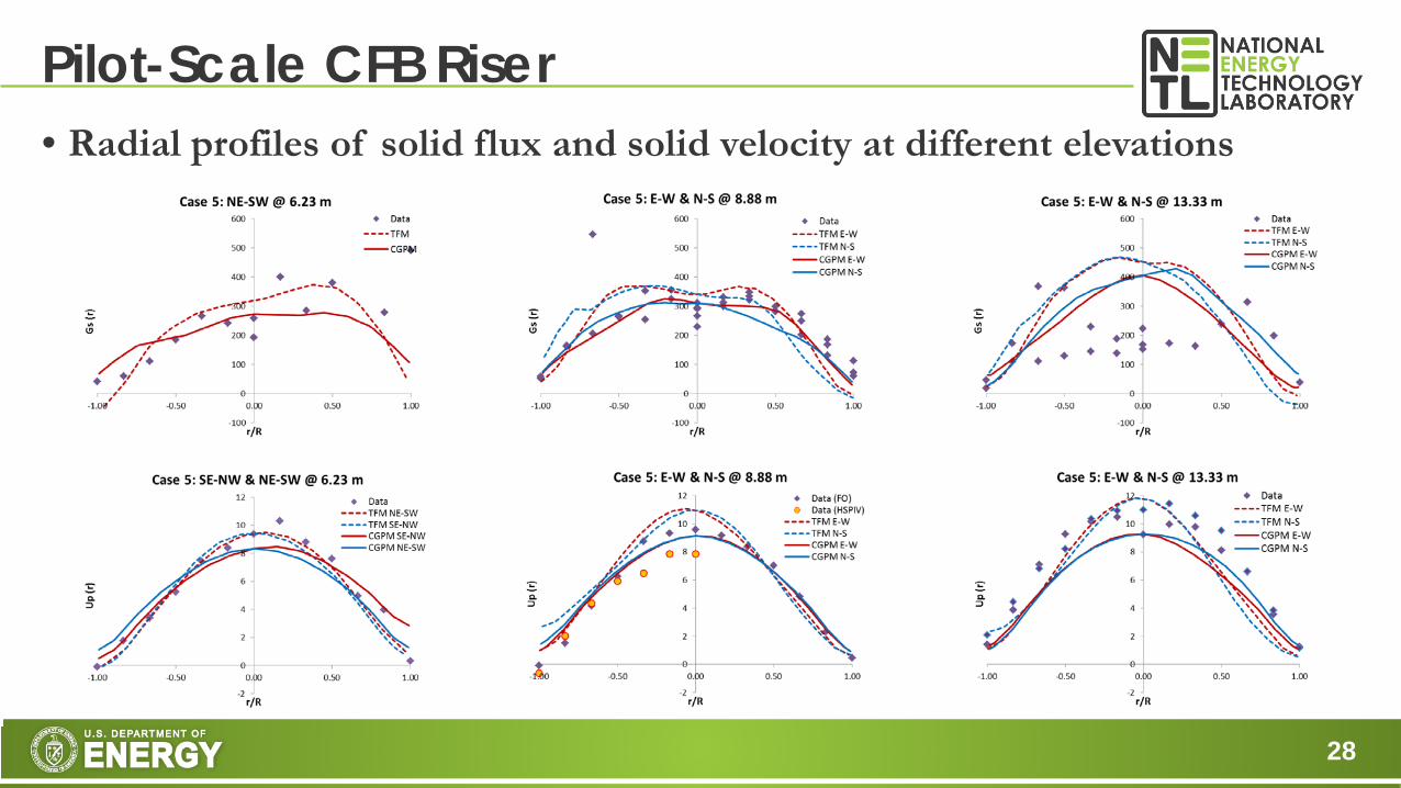
• Radial profiles of solid flux and solid velocity at different elevations
Pilot-Scale CFB Riser
29
• By coupling hard-sphere and coarse-graining, considerable speedup has be achieved in discrete particle simulations.
• The method has been verified for different gas-solid flow problems with reasonable accuracy.
• A pilot-scale CFB riser flow has been simulated with detailed validation against experimental measurements.
Summary

30
• Various computational fluid dynamic modeling tools have been developed at NETL for studying particulate multiphase flows.
• MFiX-TFM with proper constitutive models can be used for modeling reactive multiphase flow in industrial processes.
• Considerable speedup has been achieved in MFiX-DEM simulation with good accuracy.
• Continued model development is needed for better accuracy and speed.
Concluding Remarks

31
• Sofiane Benyahia, Juray DeWilde, Jeff Dietiker, Chris Guenther, Arthur Konan, Liqiang Lu, Douglas McCarty, Aaron Morris, Jordan Musser, William Rogers, Avik Sarkar, Mehrdad Shahnam, Sankaran Sundaresan, Madhava Syamlal, Dirk VanEssendelft, Vikrant Verma, Yupeng Xu
• This technical effort was performed in support of the National Energy Technology Laboratory’s ongoing research under the RES contract DE-FE0004000.
Acknowledgement
32
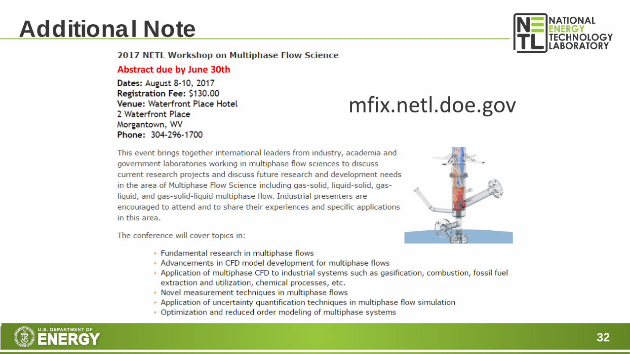
Additional Note
mfix.netl.doe.gov
Abstract due by June 30th
33
This report was prepared as an account of work sponsored by an agency of the United States Government. Neither the United States Government nor any agency thereof, nor any of their employees, makes any warranty, express or implied, or assumes any legal liability or responsibility for the accuracy, completeness, or usefulness of any information, apparatus, product, or process disclosed, or represents that its use would not infringe privately owned rights. Reference herein to any specific commercial product, process, or service by trade name, trademark, manufacturer, or otherwise does not necessarily constitute or imply its endorsement, recommendation, or favoring by the United States Government or any agency thereof. The views and opinions of authors expressed herein do not necessarily state or reflect those of the United States Government or any agency thereof.
Disclaimer

34
Contact U.S. Department of Energy
National Energy Technology Laboratory
MORGANTOWN, WV
3610 Collins Ferry Road
P.O. Box 880Morgantown, WV 26507-0880
304-285-4764
PITTSBURGH, PA
626 CochransMill Road
P.O. Box 10940
Pittsburgh, PA 15236-0940
412-386-4984
ALBANY, OR
1450 Queen Avenue SW
Albany, OR 97321-2198
541-967-5892

35
Backup Slides

36
• Gas phase (average NS equations)
• Solid phase
MFiX-TFM
( ) ( )g g gg g g g g g g gpPtε ρ ε ρ ε ε ρ∂
+∇ ⋅ = ∇ ⋅ − ∇ + −∂
τ g IV V V
( ) ( ) 0gg g g gtε ρ ε ρ∂
+∇ ⋅ =∂
V
( ) ( ) 0pp p p ptε ρ ε ρ∂
+∇ ⋅ =∂
V
• Working horse for simulating large scale fluidized bed reactors • Require many constitutive closures and hard to account for particle size
distribution, shape and inter-particle forces.
( ) ( )p p p pp p p p p p p gpPtε ρ ε ρ ε ε ρ∂
+∇ ⋅ = ∇ ⋅ − ∇ + +∂
g IV V V σ
solid fraction, velocity (left) and granular temperature (right)
1g sε ε+ =
Interphase drag
Frictional Theory Kinetic Theory for Granular Flow
3 ( ) ( ) :2 p pp p p p p p p gp p p pJ
tε ρ ε ρ ε ρ∂ Θ +∇⋅ Θ = +∇⋅ +Π − ∂
τ qV V
37
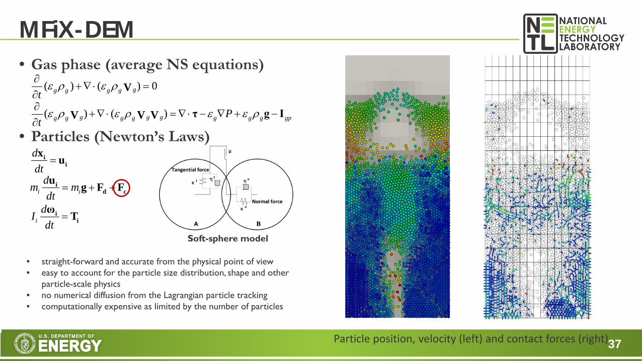
• Gas phase (average NS equations)
• Particles (Newton’s Laws)
MFiX-DEM
ddt
=ii
x u
i idm mdt
= + +id c
u g F F
idIdt
=ii
ω T
• straight-forward and accurate from the physical point of view • easy to account for the particle size distribution, shape and other
particle-scale physics • no numerical diffusion from the Lagrangian particle tracking • computationally expensive as limited by the number of particles
( ) ( )g g gg g g g g g g gpPtε ρ ε ρ ε ε ρ∂
+∇ ⋅ = ∇ ⋅ − ∇ + −∂
τ g IV V V
( ) ( ) 0gg g g gtε ρ ε ρ∂
+∇ ⋅ =∂
V
Soft-sphere model
Particle position, velocity (left) and contact forces (right)

38
• Comparison of MFiX-TFM and MFiX-DEM simulations
MFiX-TFM vs. MFiX-DEM
Bubbling bed w/o tubes Small-scale CLC
Computational Cost
Model Accuracy
Model Complexity

39
• Comparison of hard- and soft-sphere models • Soft-sphere
• Hard-sphere
Hard- and Soft-Sphere Models
( )
( ) ( )2
:
i i
i i
mdI
impulse
′ − =
′ − = ×
c c J
ω ω n J
J
( )2
:
dmdt
d dIdtcontact force
=
= ×
i
i
c F
ω n F
F
T T + ∆t T+∆tcoll
…
∆t=∆tcoll/N N=20~50
Event-driven
∆t=∆tcoll
∆tcoll=0
Time-driven

40
• Operating condition • Size: Ф0.3x16.8 m • dp: 880 µm • ρp: 863 kg/m3
• Ug,bt: 7.58 m/s • Gs: 14 kg/s
• MFiX-TFM simulations • Riser and full-loop simulations • Verification, validation & UQ
• MFiX-DEM simulation • Coarse-grain hard-sphere • Riser-only simulation
NETL CFB
Schematic of NETL B22 CFB MFiX-TFM full-loop simulation


