
Memory Upgrade
for the Fanuc 15B CNC
Installation Instructions
Copyright © 2017
Memex Automation Inc.
105 – 3425 Harvester Road Burlington, Ontario Canada
L7N 3N1
Ph: 905-635-3040 Fax: 905-631-9640
www.memex.ca
Part of the Astrix Group of Companies
\ISO9000\DOCs\M100711D – MAI Memory Upgrade for Fanuc 15B.doc

1
Quick Summary: After backing up with the PCMCIA card (and serially
backing up the part programs and macros), you can swap the Fanuc
SRAM module for the Memex one, restore the FILE1.BAK from the
PCMCIA card and then enable the 2 meg option in IPL mode and
reload the part programs (and macros) to get back up and running.
2
Table of Contents
Introduction.............................................................................. 3
General Information. .................................................. 3
About This Manual............................................................... 4
Installing the Memex Memory Upgrade.................................. 5
Backup All Parameters......................................................... 5
Backup to PCMCIA SRAM Memory Card........................ 5
Record Settings & Options................................................... 7
Backup to Computer............................................................ 8
Example Fanuc 15B CPU Board Diagram........................... 10
Upgrade Memory Size Option Parameters........................... 12
Install the New Memory Module.......................................... 15
Restore the Control............................................................. 16
Verify the Control.............................................................. 22
Installation Checklist.......................................................... 23
Fanuc 15B Technical Summary............................................. 24
Memex Technical Support & Service.................................... 27
Appendix A: Parameter Records........................................... 28

3
Introduction
Thank you for purchasing the Memex Memory Upgrade Kit for the
Fanuc 15B control. At Memex we invest a great deal of effort in the
design, manufacture and testing of each unit we build, and back it with
a three-year limited warranty. We are confident you will find this
upgrade significantly improves to your machining operations.
General Information
The installation procedure is straightforward and relatively easy to
complete – backup the parameters and programs, swap the memory
module, and restore the parameters and programs. All that’s needed are
some basic skills and hand tools. Estimated time required: 1 hour.
The Fanuc 15B can be upgraded to a maximum of 5120 meters (2
megabytes) of part program storage. The SRAM-based memory is
resident on a Single In-Line Memory Module or “SIMM” that is located
on the Main CPU board. This “CPU” board is one of the grey slots in
the yellow plastic box, close to the right side. The CPU board, once
removed, can keep the SRAM module powered for over 30 minutes via
a high capacity (1 Farad) backup capacitor.
IMPORTANT: Please see “Applicable CPU Boards” on page 10. This
SIMM must not be installed in a board not listed in the table. If the
intended CPU board is not listed, please contact Memex Technical
Support. Contact information is listed on page 20 of this manual.
Fanuc SRAM Module Listing
2MB A20B–2900–0682 Memex Module
1MB A20B–2900–0680
512KB A20B–2900–0681
256KB A20B–2900–0700
128KB A20B–2900–0701
64KB A20B–2900–0711

4
Installation Considerations
The memory upgrade should be conducted with care. Never install or
remove a board with the control power on (the main power can be on,
but not the control). Take care when handling circuit boards, as they are
static sensitive. Keep the boards in the anti-static bag provided. Do not
place the SIMM in any other slot on the Fanuc CPU board. Do not
force, drop or otherwise mishandle the boards during the installation
procedure.
About this Manual
This manual explains how to install the Memex Memory Upgrade Kit
for the Fanuc 15B control, and consists of the following sections:
Installing the Fanuc 15B Memory Upgrade explains how to install
the Memex Memory Upgrade Kit into the Fanuc 15B CNC. It consists
of sections regarding backing up the control’s memory contents to both
a PCMCIA memory card and a computer, removing the existing CNC
memory module and installing the new one, changing some settings to
use the new memory size, and restoring and verifying the control.
Fanuc 15B Technical Summary provides brief summaries of the
procedures to punch and read data, critical parameters and their
settings, serial port and cable configuration information, applicable
CPU boards and memory modules, and PC Card backup file naming
conventions.
Technical Support provides contact information for technical support
and customer service.
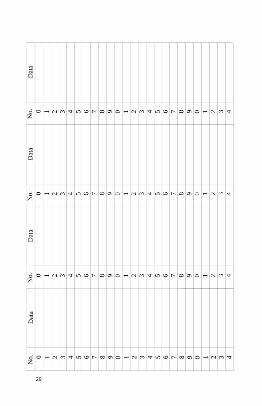
Appendix A: Parameter Records provides tables for manually
recording critical parameters before performing the memory upgrade.
These parameters must be re-entered manually before restoring the
parameter backups after the memory upgrade. It is critical that they be
copied down accurately.

5
Installing the Memex Memory Upgrade
Backup All Parameters
The Memex Memory Upgrade for Fanuc 15B kit may include an
optional PC Card Memory that allows easy backup of existing CNC
settings. The process backs up all parameters into non-volatile memory
on the card. The card may then be kept as a safety backup of the pre-
upgrade configuration in case a quick reversal of the upgrade is ever
required, or updated after the upgrade to facilitate a quick restore of the
new configuration in the event of any parameter change or loss.
Backup to PCMCIA SRAM Card
Before starting the installation, power on the control and verify that the
machine tool is in good working order. If the control has an SRAM
system error and is inoperable, then you will have to replace your
SIMM with the new one, and restore the information from existing
parameter backups.
1. Home the machine before performing the memory upgrade.
2. Insert the PCMCIA SRAM Card into the vertical MEM slot on the
CPU card in the main rack (with the top label facing left). It goes in
only a short way and can be inserted with the power ON or OFF.
3. Power ON the control holding down the Page Up and Page Down
keys to access the INITIAL PROGRAM LOAD (IPL) screen (see
note below).
4. Note that the PCMCIA card comes formatted and ready for use
already. Note that some Dell laptops have a power save mode that
can affect usage – check reading and writing capability with your
laptop before use.
5. Select the 4 for FILE menu and press INPUT to change to the CNC
SRAM Backup screen (cursor keys may be used for this as well).

6
Note: If the CNC has an Option board that also has SRAM, it needs to
be backed up as well. An intermediate menu will appear in this case.
Select each line and backup up the files indicated (if present).
SYSTEM MONITOR Screen
Select 4 for FILE Menu and Hit Enter to Get the Store, then 1 for
STORE to backup the FILE1.BAK to the PCMCIA card.

7
6. Type 1 + INPUT (or cursor to it) for the STORE (CNC-CARD).
Save the SRAM files to the PCMCIA card..
7. Back out of that menu by using the soft keys to select END. (Once
at the main menu you can check the contents of your SRAM card
by selecting MEMORY CARD FILE DELETE and just looking at
what files are available for deletion. Then back out of this menu
without deleting anything after looking.)
8. On the main screen, go to the bottom and select END, then press
YES to leave this area and reboot the control. The file(s) backed up
to the SRAM card may be checked via a notebook PC’s PCMCIA
slot. Unlike a Fanuc 16/18 the backup file name doe not change
between memory board upgrades.
Record Settings & Options – Manual Backup if Needed
Settings
1. Note which type of display monitor the control has – whether it is
colour or monochrome, 74- or 80-character width.
2. Using the forms on page 28 & 29, record SETTING (“Handy”)
screen data. To display the parameters, Press the SERVICE ,
PARAM soft keys. Enter the number of the parameter to be
displayed and press INP–NO . The screen can also be changed
using the cursor or page key.
3. Write down the serial port settings in parameters 0, 20-23 and 5000
series. The grey boxes are for the Remote Buffer Unit, if that
option card is present. Also record parameter 9000 in the space
provided under the SETTING screen chart.
Options
4. Using the form on page 28, record all parameters in the 9100
series. Using the Conversion Chart on page 28, convert the binary
values to hexadecimal format. Skip the three “Updated” boxes.

8
Backup to Computer – Manual Backup if Needed
1. If not already connected, connect the CNC to a PC with a serial
data cable (see “Standard Fanuc Serial Cable”, page 25). You will
need a communications program (such as a DNC system or at least
a terminal program) to download and upload the parameters. Make
sure the software’s communications settings match the CNC’s. NC Parameters
2. Get the computer ready to receive the NC data.
• Select EDIT mode.
• Press the SERVICE then the PARAM soft keys.
• Press the PUNCH then the PARAM softkeys.
Pitch Error Compensation
3. Get the computer ready to receive the Pitch Error Comp. data.
• Confirm that EDIT mode is selected.
• Press the SERVICE then the PITCH soft keys.
• Press the PUNCH then the PITCH softkeys. Part Programs
4. Set parameter 0011.0 and 2201.0 to 0 to unprotect part programs in
the 8000 series and 9000 series. Get the computer ready to receive
part programs.
• Confirm that EDIT mode is selected.
• Press < then PROGRAM . Press > until PUNCH appears.
• Press PUNCH then ALL . Offsets
5. Get the computer ready to receive the Tool Offset data.
• Confirm that EDIT mode is selected.
• Press < OFFSET CHAPTER TOOL > PUNCH . PMC Data – Communications Settings
7. The PMC area has a setting for baud rate that is separate from the
normal serial port settings. Set them to match the settings for other
serial communications so the PMC data can be easily backed up.
Press the CNC/PMC key to display the PMC screen. If the softkey
list matches this diagram, skip to step 8 (on the 9” CRT the “ETC.”
key switches between the two rows):
PCMDI PCLAD PDDGN PCPRM
RUN/STOP EDIT I/O SYS/PRM

9
• Press the CNC/PMC key to display the NC screen. Then put
the CNC in the MDI mode or emergency stop mode.
• Press the SETTING soft key to display the setting screen.
Enter 8000 and press the INP–NO. softkey to display
Parameter No. 8000. If PWE (8000.0) is set to 0, change it to
1. Ignore alarms.
• Press the CNC/PMC key, then the PCPRM and KEEPRL
soft keys to display the Keep Relay screen.
• Press the Page Down key until the screen that contains the
K17 data line is displayed. Record the existing value for K17
in space provided under the SETTING screen chart on page
28. Place the cursor at the K17 data using the cursor keys, and
enter 1 0 0 0 0 0 0 0 and press the INPUT soft key.
• Press the RETURN key on the right of the soft keys several
times to display the soft key menu as shown above.
8. Press the soft keys I/O , FDCAS , CHANEL . Enter the channel
number and press EXEC .
• To change the baud rate, press the PCPRM then MODE
softkeys. Then place the cursor at DATATRANSFERRATE
(AUX) using the (cursor down) key. Press the soft key to
display the desired baud rate.
• If the K17 data for the keep relay was changed in step 11,
restore it to the original setting.
PMC Data – Output
9. Get the computer ready to receive the PMC data.
• If necessary, press the NC/PC soft key to display the PMC
screen.
• Press the PCPRM soft key to display the PC parameter
screen. The soft keys are displayed as shown (on the 9” CRT
the ETC. or right most soft key to switch between the two
rows):
• Press the soft keys I/O OUTPUT PARAM CNC . Enter the
file name and press the ADD key. The corresponding
addresses are displayed to show that the data is correctly
output.
TIMER PCLAD KEEPRL DATA POS
MODE I/O CLRPRM

10
Fanuc 15B CPU Card (A16B-2201-0320) Layout Diagram
Fanuc 15B MAIN CPU Card SRAM Slot Chart:
MAIN-A A16B-2201-0300 Slot 2
MAX MAIN-A A16B-2201-0340 Slot 2
MAIN-B A16B-2201-0320 Slot 1 (above)
MAIN-C A16B-3200-0060 Slot 2
A16B-2201-0320

11
Detail showing the installation of a Memex 2 Meg SRAM card in Slot
2 of a MAIN-C A16B-3200-0060 CPU card.
Note: Slot 2 at the lower left is the SRAM slot. An existing SIMM may
or may not be present. If this diagram does not match your CPU card,
refer to your Maintenance Manual to determine the SRAM location.

12
Upgrade Memory Size Option Parameters
After restoring the PCMCIA backup files you will have to change the
option parameters via the IPL screen – power on holding “+” and “-“.
Three specific option parameters contain bits that must match the size
of memory installed. The bits turned on for the previous memory size
must be turned off, and the correct ones for the new size turned on. The
NC parameters can also be changed manually by opening the backup
file with an editor and changing the correct two bits. In either case,
record the new values in the “Updated” boxes in the form on page 22,
in both Binary and Hexadecimal format.
If changing the parameters manually, be sure to identify the existing
setting and set its corresponding bit to zero, as well as setting to 1 the
bit corresponding to the new memory size (such that only one of the
following bits is a 1 and the other six are all 0). Be sure not to change
any bits that are not listed here:
Memory Size Option 32 KB (80 M) 9110.4
64 KB (160 M) 9120.2
128 KB (320 M) 9120.3
256 KB (640 M) 9120.5
512 KB (1280 M) 9134.0
1 MB (2560 M) 9134.1
2 MB (5120 M) 9134.2
For example, if upgrading from 256 Kb to 1 Mb, #9120.5 would need
to be changed from a 1 to a 0 (xx1x xxxx xx0x xxxx) and #9134.1
from a 0 to a 1 (xxxx xx0x xxxxxx1x). It is important not to change
any other bits (represented by “x”) in each parameter.
To change parameters, you can either modify the parameter list and
upload it or hand code it in with the following procedure.
1. Get to the IPL screen.
2. Type in 99, then INPUT.
3.
If you hit INPUT only (and type in no value) the existing value will be
maintained. Change only the ones you need (turning off the old memory

13
option bits and turning on the 2 Meg option P9134 bit 2. The above
photo shows what has to be deleted (by inputting a “Y” for YES).
NOTE: Parameters referred to as a four-digit number with a decimal
place denote the parameter number and bit number. For example,
9110.4 means bit 4 of parameter #9110. Bits are ordered 76543210.

14
Therefore #9110.4 is the underlined one in “xxxxxxxx”. To get 2 megs,
add in (via an XOR or adding in the existing bits) the value of hex 04 to
Parameter 9134 (OPTION 35 as seen above).
Note that the clearing of the program directory will delete all part
program files and the macro 9000 and 8000 files. Make sure you have a
proper backup of them before you hit “Y” at this point.
If you see any other item rather than 8 to delete the PROGRAM
DIRECTORY, then you may want to say “N” and restart the “99”
procedure.

15
Install the New Memory Module
Make sure that there is a current backup of NC Parameters, Pitch Error
Compensation, Offsets, PMC Parameters and Part Programs as
explained in “Backup All Parameters” starting on page 2. The
following steps will delete all data from your control.
Remove CPU
1. With the Fanuc control powered off and the Emergency Stop
button depressed, access the yellow plastic electronic card rack.
Find Slot 1, second from the right, labelled as the Main CPU
board. Locate the tabs on the top and bottom. Squeeze the tabs and
carefully pull the board out. The unit can often be removed with all
the cables attached if the shield clamps are loosened beforehand. If
not, carefully label the cables and the points they connect to so they
can be correctly reconnected later, and remove cables as necessary.
Install Memory Module
2. Locate the existing memory module – see diagram on page 7 or
refer to your Maintenance Manual. It is labelled SRAM. Remove it
carefully by opening the small tabs and gently tilting it towards the
back. Insert the new module the same way (note the keyway). It
should click into place. Now put the CPU board back into its slot
and make sure all cables are correctly connected, well seated and
secured.
Clear Memory
3. With the “7” & “9” keys depressed, power on the control, and keep
the “7” & “9” keys depressed until you see the message “CLEAR
FILE: RAM TEST”. This will clear the entire memory module. If
the control will not power on at this point, check that main power is
restored and the cabinet door interlock is bypassed. The control
may take a few seconds to clear the entire memory.
4. NOTE: If you have a Loader OP3 board, it too will be cleared in
this procedure. It seems that TT controls are not affected however,
as the L/R switch selects the side to clear.
The SIMM has now been initialized and all parameters must be
restored.

16
Restore The Control
Restore From PCMCIA SRAM Card or From Computer
The remaining parameters may be restored from either the PCMCIA
SRAM card backup or the computer backup. Choose one of the
following two options:
Option 1: Restore From PCMCIA SRAM Card
1. Before the files on the SRAM card can be restored, they must be
renamed to correspond to the new memory size. See page 18 for
naming conventions and instructions on renaming the backup files.
2. Insert the SRAM card into the PMC CPU slot 2 (see photo at front
of manual), with the face pointing left. It goes in only a short way
and can be done with the power ON or OFF.
3. Power ON the control holding down the Page Up and Page Down
keys. The SYSTEM MONITOR SERVICE MENU screen should
appear.
4. In IPL, select the 4. FILE line and press INPUT to LOAD the
backup files. The CNC will check the PCMCIA card for the
FILEx.BAK files. Use the original FILE1.BAK and either create
blank FILEx.BAK from the 512k blank SRAM file we have on our
web site (see www.memex.ca under Support, Software Utilities at
the bottom – see SRAM2_5D.FDB and copy and rename it to get
all 5 FILEx.BAK files.
9. Proceed to reload the SRAM backup files.
10. Back out of that menu by using the soft keys to select END . On
the main screen, go to the bottom and select END , then press YES
to leave this area and reboot the control.

17
Restore Settings & Options – Manual Method if Needed
Before restoring parameters from backup copy, the settings and options
must be restored manually. The control should still be in IPL (Initial
Program Load) mode after initializing the memory.
Monitor Type
1. Select #5 and enter the type of monitor the control has:
1 = Colour, 74 character width 3 = Monochrome, 74 character width
2 = Colour, 80 character width 4 = Monochrome, 80 character width
System Label and No. of Axes
2. Type 9 9 and press INPUT . Press Y to generate the System
Label.
3. Enter the number of axes and press INPUT . This number refers
to the number of control axes (displayed on the Position screen),
not those auxiliary axes not controlled by the CNC itself. Things
such as a rotary table can be controlled either by the CNC or by its
own control. Fortunately, parameter 9000 stores the number of
control axes, so enter the value recorded for #9000 in the form on
page 21.
4. Enter the 9100 series Option parameters from the form on page 22.
These must be entered in Hexadecimal format. Be careful here,

18
since if an incorrect value is input, you must press RESET and
re-enter all options from the beginning, starting with 9 9 INPUT .
Remember to enter the updated values for Options 11 (#9110), 21
(#9120) and 35 (#9134). After entering all the 9100 series
parameters from the form, just keep pressing INPUT until it
finishes asking for the 9100 series. When the series is completed, it
will ask to erase certain files (PC/NC parameters, etc.). Press Y .
5. Press 6 and INPUT to exit IPL mode. Ignore the alarms and turn
the control power off and back on.
6.

19
Option 2: Restore From Computer
1. Set the PWE, but set all bits to 1 (set #8000 to 1111 1111).
Enable the appropriate serial port by typing in the Setting
(“Handy”) screen data from the form on page 21.
Restore NC Parameters
2. Get the computer ready to send the NC data. Make sure its serial
communications settings match the CNC’s corresponding settings.
• Select EDIT mode, and turn the Program Protect key OFF.
• Press softkeys SERVICE PARAM READ ALL .
• Send the data from the computer.
Restore PMC Data
3. Get the computer ready to send the PMC data. Make sure the CNC
is ready to receive the PMC data - see “PMC Data –
Communications Settings” on page 5. If the control has special
options, such as a 5th axis table, you might need to power on in IPL
mode (holding - & . ) and then select a boot without the ladder
running.
Load the PMC data as follows:
4. If necessary, press the NC/PC soft key to display the PMC screen.
Press the PCPRM soft key to display the PC parameter screen.
The soft keys are displayed as shown (on the 9” CRT the ETC.
key switches between the two rows):
5. Press the I/O soft key, then INPUT . Enter the file name and press
EXEC . Send the data from the computer. The corresponding
addresses are displayed to show that the data is correctly input.
NOTE: When data is read, if RAM ENABLE OFF is displayed, this
means that the RAM for the PMC is protected. Press the MODE
softkey, place the cursor at RAM ENABLE using the key and press
the ON softkey.
TIMER PCLAD KEEPRL DATA POS
MODE I/O CLRPRM

20
Restore Pitch Error Compensation
6. Get the computer ready to send the Pitch Error Comp. data.
• Confirm EDIT mode is selected.
• Press the SERVICE then the PITCH softkeys.
• Press READ then ALL .
• Send the data from the computer.
Restore Offsets
7. Get the computer ready to send the Tool Offset data.
• Confirm EDIT mode is selected.
• Press < PROGRAM .
• Press > until the READ softkey appears.
• Press READ .
• Enter a program number (that’s not being used). Press EXEC .
• Switch to MEMORY mode. Press the CYCLE START button.
• Once the program finished executing, delete it.
Restore Part Programs
8. Set parameter 0011.0 and 2201.0 to 0 to unprotect part programs in
the 8000 and 9000 series.
• Confirm EDIT mode is selected.
• Press < PROGRAM .
• Press > until the READ softkey appears.
• Press READ ALL .
• Send the part programs from the computer.

21
Verify The Control
Once the upgrade is completed, including the reloading of all
parameters, test the machine via the following procedure.
IMPORTANT: Do not move the machine until you are sure all
parameters have been restored.
• Change to either MDI mode or Program mode.
• Home all axes, tool changers and pallets.
• Check spindle functionality through all speeds and gear ranges.
• Check Clockwise and Counter-clockwise spindle rotation with M3
and M4 commands.
• Check the tool changer. Be sure that the tool received was the tool
requested and that the carousel rotates in the proper direction.
• Check the pallet changer (if applicable). If the machine requires
special custom macros for a pallet changer or tool changer, be sure
that they are present.
Option: Update PCMCIA SRAM Card
Now that the control is set to work with the new memory size, the
PCMCIA memory card can either be updated with the new parameters
to act as a safety backup of the new configuration (refer to “Backup to
PCMCIA SRAM Card” on page 8), or kept as is as a convenient means
of restoring the control to the previous (pre-upgrade) state.

22
Installation Checklist
• Check machine - Power ON and check for problems before
starting.
• Backup settings, options, parameters and programs.
• Power OFF.
• Depress E-STOP.
• Backup with PCMCIA card – power on with Page Up & Page
Down
• Unprotect macro programs (9000s), then backup part
programs.
• Power Off
• Change old Fanuc SRAM card with Memex 2 Meg one.
• Power On the Control with 7 & 9 to clear all.
• Power off, Power on Holding Page Up & Page Down – restore
the FILE1.BAK (and other files).
• Cycle the Power – power up holding “+” & “-“ for the IPL
screen
• Perform the 99 sequence with the 21 digit passcode and add in
the bit 3 of P9134 (04 usually) to get the option enabled.
• Set PWE to enable.
• Restore settings & options.
• Restore parameters & part programs.
• Check the parameters and machine operation thoroughly.
23
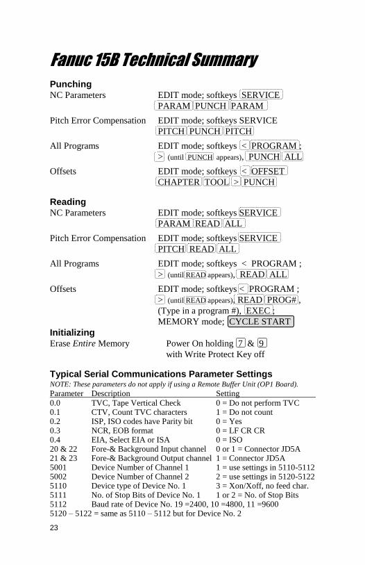
Fanuc 15B Technical Summary
Punching NC Parameters EDIT mode; softkeys SERVICE
PARAM PUNCH PARAM
Pitch Error Compensation EDIT mode; softkeys SERVICE
PITCH PUNCH PITCH
All Programs EDIT mode; softkeys < PROGRAM ;
> (until PUNCH appears), PUNCH ALL
Offsets EDIT mode; softkeys < OFFSET
CHAPTER TOOL > PUNCH
Reading NC Parameters EDIT mode; softkeys SERVICE
PARAM READ ALL
Pitch Error Compensation EDIT mode; softkeys SERVICE
PITCH READ ALL
All Programs EDIT mode; softkeys < PROGRAM ;
> (until READ appears), READ ALL
Offsets EDIT mode; softkeys < PROGRAM ;
> (until READ appears), READ PROG# ,
(Type in a program #), EXEC ;
MEMORY mode; CYCLE START
Initializing Erase Entire Memory Power On holding 7 & 9
with Write Protect Key off
Typical Serial Communications Parameter Settings NOTE: These parameters do not apply if using a Remote Buffer Unit (OP1 Board).
Parameter Description Setting 0.0 TVC, Tape Vertical Check 0 = Do not perform TVC 0.1 CTV, Count TVC characters 1 = Do not count 0.2 ISP, ISO codes have Parity bit 0 = Yes 0.3 NCR, EOB format 0 = LF CR CR 0.4 EIA, Select EIA or ISA 0 = ISO 20 & 22 Fore-& Background Input channel 0 or 1 = Connector JD5A 21 & 23 Fore-& Background Output channel 1 = Connector JD5A 5001 Device Number of Channel 1 1 = use settings in 5110-5112 5002 Device Number of Channel 2 2 = use settings in 5120-5122 5110 Device type of Device No. 1 3 = Xon/Xoff, no feed char. 5111 No. of Stop Bits of Device No. 1 1 or 2 = No. of Stop Bits 5112 Baud rate of Device No. 19 =2400, 10 =4800, 11 =9600 5120 – 5122 = same as 5110 – 5112 but for Device No. 2

24
Applicable CPU Boards
A16B-2201-0320 A16B-2201-0300
A16B-2201-0340 A16B-3200-0060
Available Memory Modules
Fanuc Part Number Type Size
A20B-2900-0711 A 64 KB
A20B-2900-0701 B 128 KB
A20B-2900-0700 C 256 KB
A20B-2900-0681 D 512 KB
A20B-2900-0680 E 1 MB
A20B-2900-0682 F 2 MB
Standard Fanuc Serial Port: (db25 Female)
1 = Frame Ground 6 = Data Set Ready
2 = Transmit Data 7 = Signal Ground
3 = Receive Data 8 = Carrier Detect
4 = Ready To Send 20 = Data Terminal Ready
5 = Clear To Send 25 = +24 Volts
Standard Fanuc Serial Cable
Computer Fanuc
25-pin Female to 25-pin Male
Tx – 2 - 3 – Rx Rx – 3 - 2 – Tx
RTS – 4 - 5 – CTS CTS – 5 - 4 – RTS SG – 7 - 7 – SG
6-8-20 jumpered FG – 1 - No Connection
9-pin Female to 25-pin Male
Tx – 3 - 3 – Rx Rx – 2 - 2 – Tx
RTS – 7 - 5 – CTS CTS – 8 - 4 – RTS SG – 5 - 7 – SG
6-8-20 jumpered FG – (D-shell) - No Connection

25
Fanuc Protocol: E,7,x
The standard serial communications protocol for Fanuc controls is
always Even Parity and 7 Data Bits. Stop Bits are either 1 or 2, as set
via parameter 5111 or 5120 (see “Typical Serial Communications
Parameter Settings” on page 23).
PCMCIA Memory Card File Naming Conventions
The file(s) saved on the PCMCIA memory card during backup are
named according to a set of naming schemes, depending upon memory
module size. When performing a restore operation after a memory
upgrade, files backed up from a different memory size can be used to
fill the larger new memory board in part.
Memory PCMCIA Backup File Naming Scheme
256k-512K FILE1.BAK (original)
2 Megs FILE1.BAK (same as original)
FILE2.BAK
FILE3.BAK
FILE4.BAK
FILE5.BAK
Note: When upgrading to 2 Megs, the missing files can be ignored or
if you download the blank 512k file we have on our web site called
“SRAM2_5B.FDB” in the software utilities area. The missing BAK
files can be created with this file – copy and rename it until you have all
the files needed. This process also enables a clearing of memory as
“0’s” are written to the memory in the 512k sectors related to the files. Fanuc SRAM Module Listing 2MB A20B–2900–0682 Memex Module 1MB A20B–2900–0680 512KB A20B–2900–0681 256KB A20B–2900–0700 128KB A20B–2900–0701 64KB A20B–2900–0711

26
Memex Technical Support & Service
In case of technical difficulty with the memory upgrade procedure,
please contact your Memex dealer, or call Memex Automation
Technical Support at 1-905-635-1540.
The next pages of this manual may be used to record technical
information, service advice, etc. as needed.
If you have any other questions or concerns, need answers to technical
questions, or need information about Memex products and/or services,
please contact your local Memex dealer, or contact Memex
Automation:
Memex Autmation Inc.
200-3425 Harvester Road
Burlington, Ontario Canada L7N 3N1
Phone: 905-635-1540 Fax: 905-631-9640
Web: www.memex.ca

27
Appendix A: Parameter Records
Ser
ial
Com
mu
nic
ati
on
s P
ara
met
ers
Par
.#V
alue
0
20 21
50
00
22
23
Par
.#V
alue
Par
.#V
alue
Par
.#V
alue
Par
.#V
alue
Par
.#V
alue
50
01
50
02
50
70
50
71
50
72
50
73
50
74
50
81
50
82
50
83
50
84
51
10
51
11
51
12
51
20
51
21
51
22
No
te:
Gre
y b
oxe
s a
re f
or
Re
mo
te B
uff
er
Un
it (
RB
U b
oa
rd,
lab
elle
d "
OP
1")
.
Fan
uc
Sy
stem
15B
Mac
hin
e P
aram
eter
Wo
rksh
eet
Fan
uc
15B
S
oft
war
e V
ersi
on
: __
__
__
__
__
__
__
_M
ain C
PU
Bo
ard
No.:
__
__
__
__
__
__
__
__
__
__
__
__
__
__
__
__
__
_
Set
tin
g D
ata
Scr
een
Par
amet
er W
rite
TV
Chec
k
Seq
uen
ce S
top (
Pro
gra
m N
o.)
Pu
nch
Cod
e
Seq
uen
ce S
top (
Seq
uen
ce N
o.)
Inpu
t U
nit
X A
xis
Mir
ror
I/O
Chan
nel
Y A
xis
Mir
ror
Com
pan
y:_
___
__
__
__
__
__
__
__
__
__
__
__
__
__
__
Mac
hin
e N
o.:
__
__
__
__
__
__
__
__
Dat
e:__
__
__
__
__
__
__
__
_
#9
00
0
#K
17
No
. o
f A
xes
:
PM
C P
aram
eter
Tra
nsf
er C
on
trol:
Bin
ary
to
Hex
ad
ecim
al
Con
ver
sion
Exam
ple
: 11
01
01
01
1 1
0 1
=
0 1
0 1
=
11
01
010
1 =
Bin
ary
Hex 0 1 2 3
Bin
ary
Hex 4 5 6 7
Bin
ary
Hex 8 9
Bin
ary
Hex C D E F
D5
D 5
0 0
0 0
0 0
0 1
0 0
1 0
0 0
1 1
0 1
0 0
0 1
0 1
0 1
1 0
0 1
1 1
1 0
0 0
1 0
0 1
1 0
1 0
1 0
1 1
1 1
0 0
1 1
0 1
1 1
1 0
1 1
1 1
A B

28
Op
tion
Pa
ram
eter
s
Par
.#
91
00
91
01
91
02
91
03
91
04
91
05
Bin
ary
Hex
OP
#P
ar.#
91
20
91
21
91
22
Bin
ary
Hex
OP
#P
ar.#
91
40
91
41
91
42
91
43
91
44
91
45
Bin
ary
Hex
OP
#
91
06
91
07
91
08
91
09
91
46
91
47
91
48
91
49
OP
1
OP
2
OP
3
OP
4
OP
5
OP
6
OP
7
OP
8
OP
9
OP
10
OP
21
OP
22
OP
23
OP
24
OP
25
OP
26
OP
27
OP
28
OP
29
OP
30
91
10
91
11
91
50
91
51
91
12
91
13
91
14
91
52
91
53
91
54
OP
11
OP
12
OP
13
OP
14
OP
15
OP
31
OP
32
OP
33
OP
34
OP
35
91
15
91
16
91
55
91
56
91
17
91
18
91
19
91
57
91
58
91
59
OP
16
OP
17
OP
18
OP
19
OP
20
OP
36
OP
37
OP
38
OP
39
OP
40
91
35
91
36
91
37
91
38
91
39
91
23
91
24
91
25
91
26
91
27
91
28
91
29
91
30
91
31
91
32
91
33
91
34
OP
50
OP
51
OP
52
OP
53
OP
54
OP
55
OP
56
OP
57
OP
58
OP
59
OP
60
OP
41
OP
42
OP
43
OP
44
OP
45
OP
46
OP
47
OP
48
OP
49
NO
TE
: A
ne
we
r m
ac
hin
e m
ay
ha
ve
mo
re 9
10
0 s
eri
es
pa
ram
ete
rs -
it
is im
pe
rati
ve
to
re
co
rd t
he
m a
ll.
91
10
OP
11
91
20
OP
21
OP
35
91
34
- O
rigin
al
- U
pd
ated
- O
rigin
al
- U
pd
ated
- O
rigin
al
- U
pd
ated
29
1 2 3 4 5 6 7 8 9
No
. 0
Dat
a
0 1 2 3 4 5 6 7 8 9 0 1 2 3 4
1 2 3 4 5 6 7 8 9
No
. 0
Dat
a
0 1 2 3 4 5 6 7 8 9 0 1 2 3 4
1 2 3 4 5 6 7 8 9
No
. 0
Dat
a
0 1 2 3 4 5 6 7 8 9 0 1 2 3 4
1 2 3 4 5 6 7 8 9
No
. 0
Dat
a
0 1 2 3 4 5 6 7 8 9 0 1 2 3 4

30
1 2 3 4 5 6 7 8 9
No
. 0
Dat
a
0 1 2 3 4 5 6 7 8 9 0 1 2 3 4
1 2 3 4 5 6 7 8 9
No
. 0
Dat
a
0 1 2 3 4 5 6 7 8 9 0 1 2 3 4
1 2 3 4 5 6 7 8 9
No
. 0
Dat
a
0 1 2 3 4 5 6 7 8 9 0 1 2 3 4
1 2 3 4 5 6 7 8 9
No
. 0
Dat
a
0 1 2 3 4 5 6 7 8 9 0 1 2 3 4

31
Memex Automation Inc. 105 – 3425 Harvester Rd.
Burlington, Ontario Canada L7N 3N1
Phone: 905-635-1540 Fax: 905-631-9640 www.memex.ca
Thank you for using Memex products
Sales: (905) 635-3043
Support: (905) 635-3041
\ISO9000\DOCs\M100711D – MAI Memory Upgrade for Fanuc 15B.doc


