
Memory Scaling: A Systems Architecture Perspective
Onur Mutlu [email protected] August 6, 2013 MemCon 2013

The Main Memory System
n Main memory is a critical component of all computing systems: server, mobile, embedded, desktop, sensor
n Main memory system must scale (in size, technology, efficiency, cost, and management algorithms) to maintain performance growth and technology scaling benefits
2
Processor and caches
Main Memory Storage (SSD/HDD)

Memory System: A Shared Resource View
3
Storage

State of the Main Memory System n Recent technology, architecture, and application trends
q lead to new requirements q exacerbate old requirements
n DRAM and memory controllers, as we know them today, are (will be) unlikely to satisfy all requirements
n Some emerging non-volatile memory technologies (e.g., PCM) enable new opportunities: memory+storage merging
n We need to rethink the main memory system q to fix DRAM issues and enable emerging technologies q to satisfy all requirements
4

Agenda
n Major Trends Affecting Main Memory n The DRAM Scaling Problem and Solution Directions
q Tolerating DRAM: New DRAM Architectures q Enabling Emerging Technologies: Hybrid Memory Systems
n How Can We Do Better? n Summary
5

Major Trends Affecting Main Memory (I) n Need for main memory capacity, bandwidth, QoS increasing
n Main memory energy/power is a key system design concern
n DRAM technology scaling is ending
6

Major Trends Affecting Main Memory (II) n Need for main memory capacity, bandwidth, QoS increasing
q Multi-core: increasing number of cores/agents q Data-intensive applications: increasing demand/hunger for data q Consolidation: cloud computing, GPUs, mobile, heterogeneity
n Main memory energy/power is a key system design concern
n DRAM technology scaling is ending
7

Example: The Memory Capacity Gap
n Memory capacity per core expected to drop by 30% every two years n Trends worse for memory bandwidth per core!
8
Core count doubling ~ every 2 years DRAM DIMM capacity doubling ~ every 3 years

Major Trends Affecting Main Memory (III) n Need for main memory capacity, bandwidth, QoS increasing
n Main memory energy/power is a key system design concern
q ~40-50% energy spent in off-chip memory hierarchy [Lefurgy, IEEE Computer 2003]
q DRAM consumes power even when not used (periodic refresh)
n DRAM technology scaling is ending
9

Major Trends Affecting Main Memory (IV) n Need for main memory capacity, bandwidth, QoS increasing
n Main memory energy/power is a key system design concern
n DRAM technology scaling is ending
q ITRS projects DRAM will not scale easily below X nm q Scaling has provided many benefits:
n higher capacity (density), lower cost, lower energy
10

Agenda
n Major Trends Affecting Main Memory n The DRAM Scaling Problem and Solution Directions
q Tolerating DRAM: New DRAM Architectures q Enabling Emerging Technologies: Hybrid Memory Systems
n How Can We Do Better? n Summary
11

The DRAM Scaling Problem n DRAM stores charge in a capacitor (charge-based memory)
q Capacitor must be large enough for reliable sensing q Access transistor should be large enough for low leakage and high
retention time q Scaling beyond 40-35nm (2013) is challenging [ITRS, 2009]
n DRAM capacity, cost, and energy/power hard to scale
12
Solutions to the DRAM Scaling Problem
n Two potential solutions q Tolerate DRAM (by taking a fresh look at it) q Enable emerging memory technologies to eliminate/minimize
DRAM
n Do both q Hybrid memory systems
13

Solution 1: Tolerate DRAM n Overcome DRAM shortcomings with
q System-DRAM co-design q Novel DRAM architectures, interface, functions q Better waste management (efficient utilization)
n Key issues to tackle q Reduce refresh energy q Improve bandwidth and latency q Reduce waste q Enable reliability at low cost
n Liu, Jaiyen, Veras, Mutlu, “RAIDR: Retention-Aware Intelligent DRAM Refresh,” ISCA 2012. n Kim, Seshadri, Lee+, “A Case for Exploiting Subarray-Level Parallelism in DRAM,” ISCA 2012. n Lee+, “Tiered-Latency DRAM: A Low Latency and Low Cost DRAM Architecture,” HPCA 2013. n Liu+, “An Experimental Study of Data Retention Behavior in Modern DRAM Devices” ISCA’13. n Seshadri+, “RowClone: Fast and Efficient In-DRAM Copy and Initialization of Bulk Data,” 2013.
14

Solution 2: Emerging Memory Technologies n Some emerging resistive memory technologies seem more
scalable than DRAM (and they are non-volatile) n Example: Phase Change Memory
q Expected to scale to 9nm (2022 [ITRS]) q Expected to be denser than DRAM: can store multiple bits/cell
n But, emerging technologies have shortcomings as well q Can they be enabled to replace/augment/surpass DRAM?
n Lee, Ipek, Mutlu, Burger, “Architecting Phase Change Memory as a Scalable DRAM Alternative,” ISCA 2009, CACM 2010, Top Picks 2010.
n Meza, Chang, Yoon, Mutlu, Ranganathan, “Enabling Efficient and Scalable Hybrid Memories,” IEEE Comp. Arch. Letters 2012.
n Yoon, Meza et al., “Row Buffer Locality Aware Caching Policies for Hybrid Memories,” ICCD 2012. n Kultursay+, “Evaluating STT-RAM as an Energy-Efficient Main Memory Alternative,” ISPASS 2013.
15

Hybrid Memory Systems
Meza+, “Enabling Efficient and Scalable Hybrid Memories,” IEEE Comp. Arch. Letters, 2012. Yoon, Meza et al., “Row Buffer Locality Aware Caching Policies for Hybrid Memories,” ICCD 2012 Best Paper Award.
CPU DRAMCtrl
Fast, durable Small,
leaky, volatile, high-cost
Large, non-volatile, low-cost Slow, wears out, high active energy
PCM Ctrl DRAM Phase Change Memory (or Tech. X)
Hardware/software manage data allocation and movement to achieve the best of multiple technologies

An Orthogonal Issue: Memory Interference
Main Memory
17
Core Core
Core Core
Cores’ interfere with each other when accessing shared main memory
n Problem: Memory interference between cores is uncontrolled à unfairness, starvation, low performance à uncontrollable, unpredictable, vulnerable system
n Solution: QoS-Aware Memory Systems q Hardware designed to provide a configurable fairness substrate
n Application-aware memory scheduling, partitioning, throttling
q Software designed to configure the resources to satisfy different QoS goals
n QoS-aware memory controllers and interconnects can provide predictable performance and higher efficiency
An Orthogonal Issue: Memory Interference

Agenda
n Major Trends Affecting Main Memory n The DRAM Scaling Problem and Solution Directions
q Tolerating DRAM: New DRAM Architectures q Enabling Emerging Technologies: Hybrid Memory Systems
n How Can We Do Better? n Summary
19
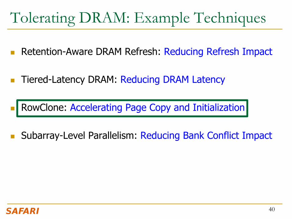
Tolerating DRAM: Example Techniques
n Retention-Aware DRAM Refresh: Reducing Refresh Impact n Tiered-Latency DRAM: Reducing DRAM Latency
n RowClone: Accelerating Page Copy and Initialization
n Subarray-Level Parallelism: Reducing Bank Conflict Impact
20

DRAM Refresh n DRAM capacitor charge leaks over time
n The memory controller needs to refresh each row periodically to restore charge q Activate each row every N ms q Typical N = 64 ms
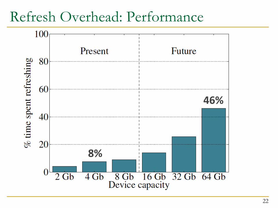
n Downsides of refresh -- Energy consumption: Each refresh consumes energy
-- Performance degradation: DRAM rank/bank unavailable while refreshed
-- QoS/predictability impact: (Long) pause times during refresh -- Refresh rate limits DRAM capacity scaling 21
Refresh Overhead: Performance
22
8%
46%

Refresh Overhead: Energy
23
15%
47%

Retention Time Profile of DRAM
24

RAIDR: Eliminating Unnecessary Refreshes n Observation: Most DRAM rows can be refreshed much less often
without losing data [Kim+, EDL’09][Liu+ ISCA’13]
n Key idea: Refresh rows containing weak cells more frequently, other rows less frequently
1. Profiling: Profile retention time of all rows 2. Binning: Store rows into bins by retention time in memory controller
Efficient storage with Bloom Filters (only 1.25KB for 32GB memory) 3. Refreshing: Memory controller refreshes rows in different bins at different rates
n Results: 8-core, 32GB, SPEC, TPC-C, TPC-H q 74.6% refresh reduction @ 1.25KB storage q ~16%/20% DRAM dynamic/idle power reduction q ~9% performance improvement q Benefits increase with DRAM capacity
25 Liu et al., “RAIDR: Retention-Aware Intelligent DRAM Refresh,” ISCA 2012.

Going Forward
n How to find out and expose weak memory cells/rows q Early analysis of modern DRAM chips:
n Liu+, “An Experimental Study of Data Retention Behavior in Modern DRAM Devices: Implications for Retention Time Profiling Mechanisms”, ISCA 2013.
n Low-cost system-level tolerance of DRAM errors
n Tolerating cell-to-cell interference at the system level q For both DRAM and Flash. Early analysis of Flash chips:
n Cai+, “Program Interference in MLC NAND Flash Memory: Characterization, Modeling, and Mitigation,” ICCD 2013.
26

Tolerating DRAM: Example Techniques
n Retention-Aware DRAM Refresh: Reducing Refresh Impact n Tiered-Latency DRAM: Reducing DRAM Latency
n RowClone: Accelerating Page Copy and Initialization
n Subarray-Level Parallelism: Reducing Bank Conflict Impact
27
28
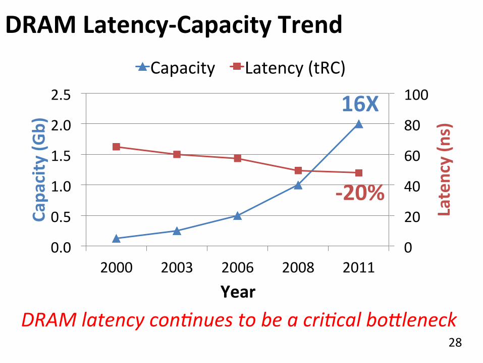
DRAM Latency-‐Capacity Trend
0
20
40
60
80
100
0.0
0.5
1.0
1.5
2.0
2.5
2000 2003 2006 2008 2011
Latency (ns)
Capa
city (G
b)
Year
Capacity Latency (tRC)
16X
-‐20%
DRAM latency con.nues to be a cri.cal bo4leneck

29
DRAM Latency = Subarray Latency + I/O Latency
What Causes the Long Latency? DRAM Chip
channel
cell array
I/O
DRAM Chip
channel
I/O
subarray
DRAM Latency = Subarray Latency + I/O Latency
Dominant Suba
rray
I/O
30
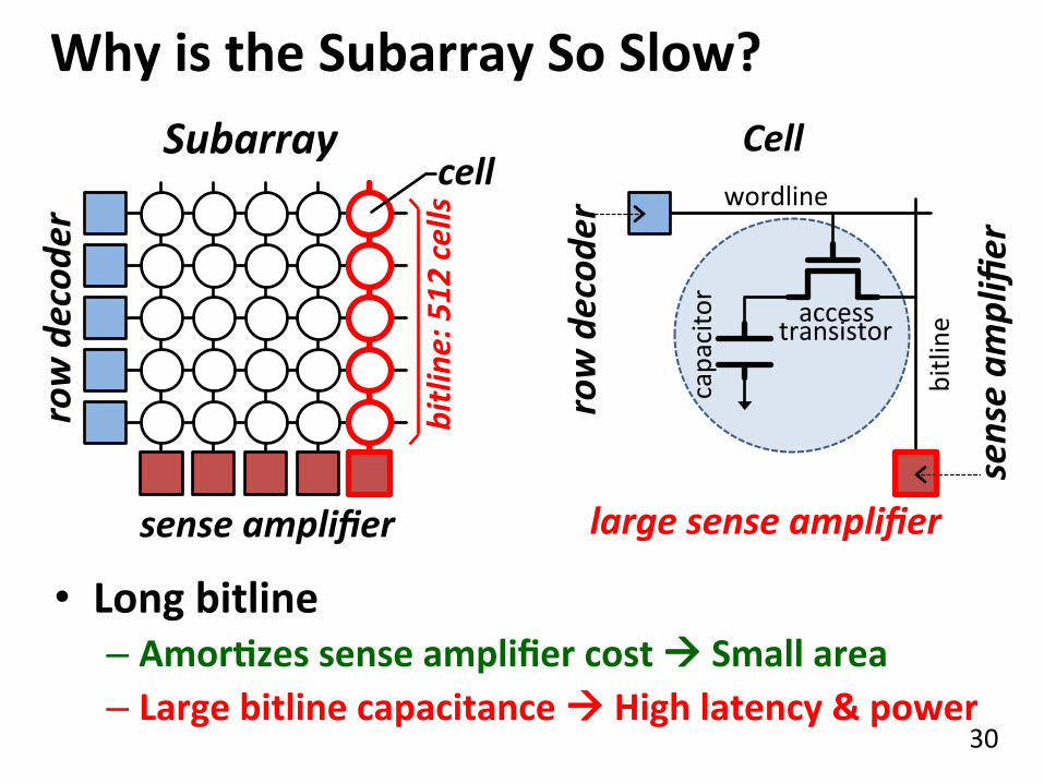
Why is the Subarray So Slow? Subarray
row decod
er
sense amplifier
capacitor
access transistor
wordline
bitline
Cell
large sense amplifier
bitline
: 512 cells cell
• Long bitline – AmorQzes sense amplifier cost à Small area – Large bitline capacitance à High latency & power
sense am
plifier
row decod
er
31
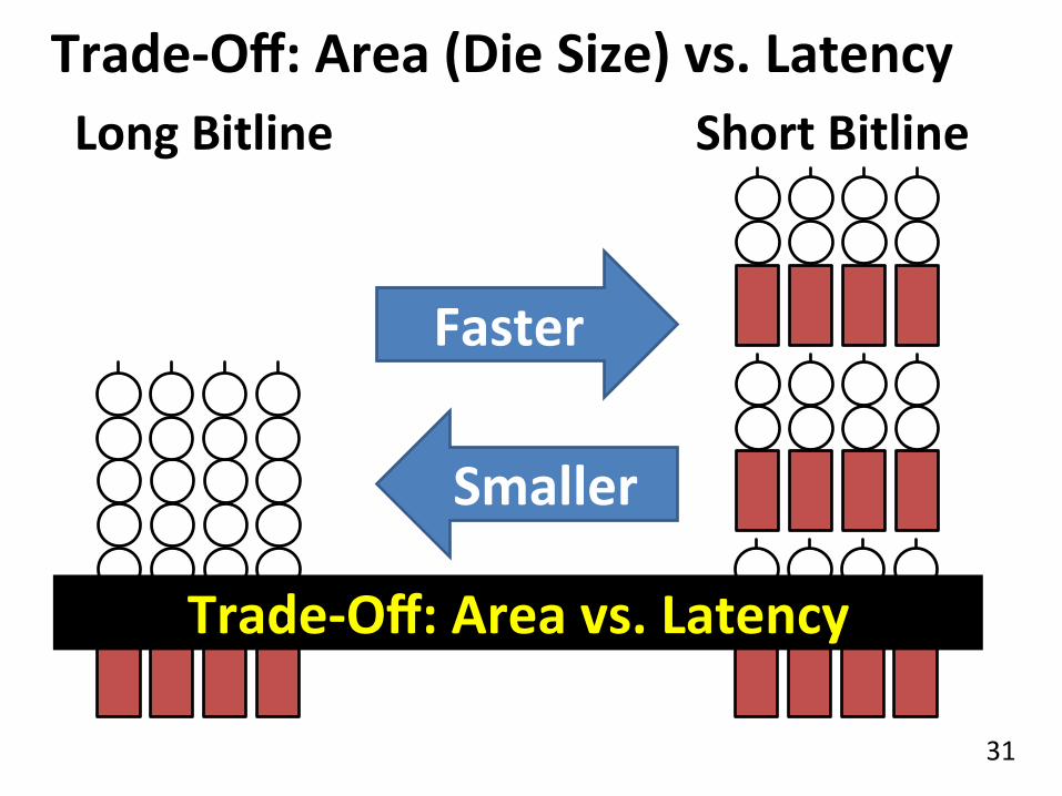
Trade-‐Off: Area (Die Size) vs. Latency
Faster
Smaller
Short Bitline
Long Bitline
Trade-‐Off: Area vs. Latency
32
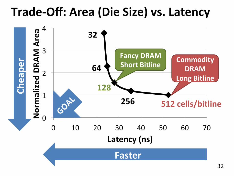
Trade-‐Off: Area (Die Size) vs. Latency
0
1
2
3
4
0 10 20 30 40 50 60 70
Normalized
DRA
M Area
Latency (ns)
64
32
128 256 512 cells/bitline
Commodity DRAM
Long Bitline
Cheape
r
Faster
Fancy DRAM Short Bitline

33
Short Bitline
Low Latency
ApproximaQng the Best of Both Worlds Long Bitline
Small Area
Long Bitline
Low Latency
Short Bitline Our Proposal Small Area
Short Bitline è Fast Need
IsolaGon Add IsolaGon Transistors
High Latency
Large Area

34
ApproximaQng the Best of Both Worlds
Low Latency
Our Proposal Small Area
Long Bitline Small Area
Long Bitline
High Latency
Short Bitline
Low Latency
Short Bitline Large Area
Tiered-‐Latency DRAM
Low Latency
Small area using long bitline

35
Tiered-‐Latency DRAM
Near Segment
Far Segment
IsolaGon Transistor
• Divide a bitline into two segments with an isolaQon transistor
Sense Amplifier
Lee+, “Tiered-Latency DRAM: A Low Latency and Low Cost DRAM Architecture,” HPCA 2013.

36
0%
50%
100%
150%
0%
50%
100%
150%
Commodity DRAM vs. TL-‐DRAM Latency
Power
–56%
+23%
–51%
+49% • DRAM Latency (tRC) • DRAM Power
• DRAM Area Overhead ~3%: mainly due to the isolaIon transistors
TL-‐DRAM Commodity
DRAM Near Far Commodity
DRAM Near Far TL-‐DRAM
(52.5ns)

37
Trade-‐Off: Area (Die-‐Area) vs. Latency
0
1
2
3
4
0 10 20 30 40 50 60 70
Normalized
DRA
M Area
Latency (ns)
64
32
128 256 512 cells/bitline
Cheape
r
Faster
Near Segment Far Segment
38
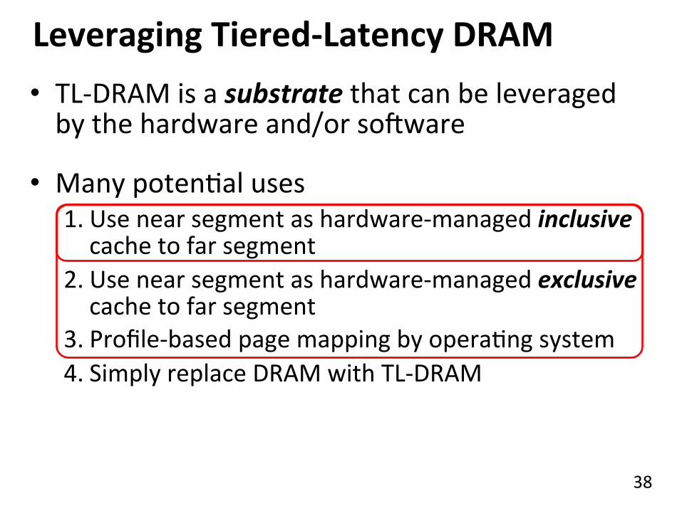
Leveraging Tiered-‐Latency DRAM • TL-‐DRAM is a substrate that can be leveraged by the hardware and/or soOware
• Many potenIal uses 1. Use near segment as hardware-‐managed inclusive cache to far segment
2. Use near segment as hardware-‐managed exclusive cache to far segment
3. Profile-‐based page mapping by operaIng system 4. Simply replace DRAM with TL-‐DRAM

39
0%
20%
40%
60%
80%
100%
120%
1 (1-‐ch) 2 (2-‐ch) 4 (4-‐ch) 0%
20%
40%
60%
80%
100%
120%
1 (1-‐ch) 2 (2-‐ch) 4 (4-‐ch)
Performance & Power ConsumpQon 11.5%
Normalized
Perform
ance
Core-‐Count (Channel) Normalized
Pow
er Core-‐Count (Channel)
10.7%
12.4% –23%
–24%
–26%
Using near segment as a cache improves performance and reduces power consumpGon
Tolerating DRAM: Example Techniques
n Retention-Aware DRAM Refresh: Reducing Refresh Impact n Tiered-Latency DRAM: Reducing DRAM Latency
n RowClone: Accelerating Page Copy and Initialization
n Subarray-Level Parallelism: Reducing Bank Conflict Impact
40
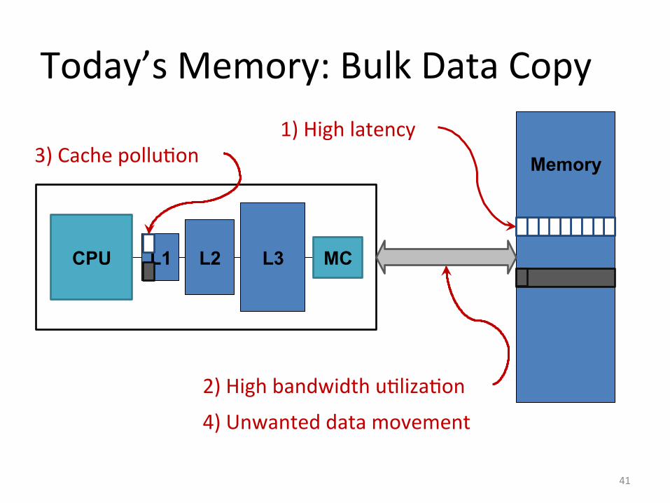
Today’s Memory: Bulk Data Copy
Memory
MC L3 L2 L1 CPU
1) High latency
2) High bandwidth uIlizaIon
3) Cache polluIon
4) Unwanted data movement
41
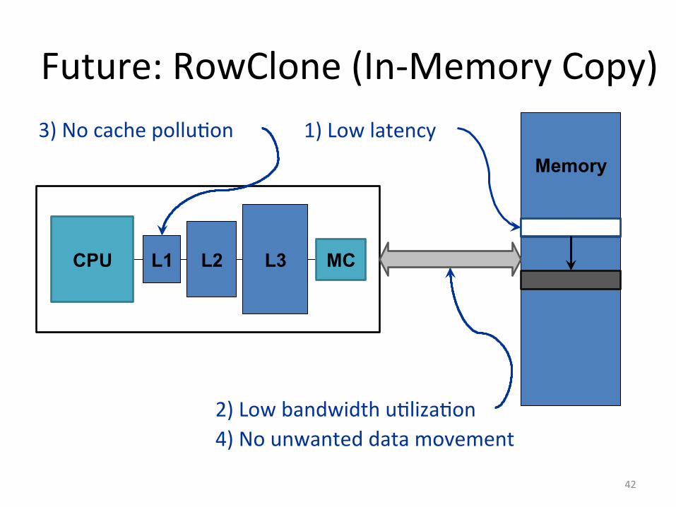
Future: RowClone (In-‐Memory Copy)
Memory
MC L3 L2 L1 CPU
1) Low latency
2) Low bandwidth uIlizaIon
3) No cache polluIon
4) No unwanted data movement
42
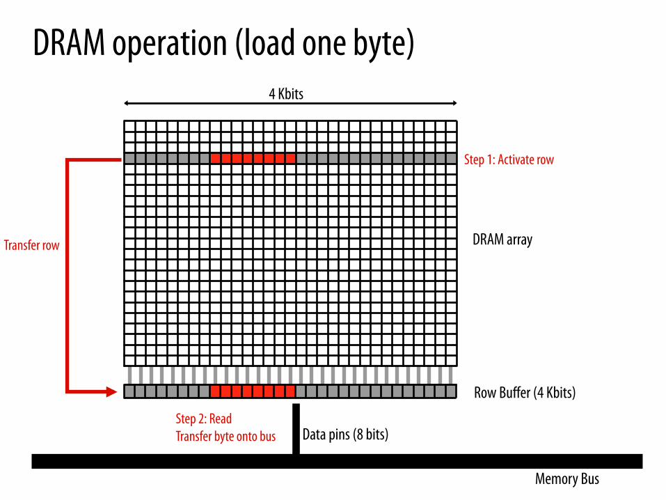
DRAM operation (load one byte)
Row Buffer (4 Kbits)
Memory Bus
Data pins (8 bits)
DRAM array
4 Kbits
Step 1: Activate row
Transfer row
Step 2: Read Transfer byte onto bus
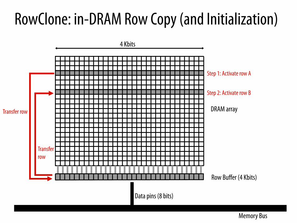
RowClone: in-DRAM Row Copy (and Initialization)
Row Buffer (4 Kbits)
Memory Bus
Data pins (8 bits)
DRAM array
4 Kbits
Step 1: Activate row A
Transfer row
Step 2: Activate row B
Transfer row
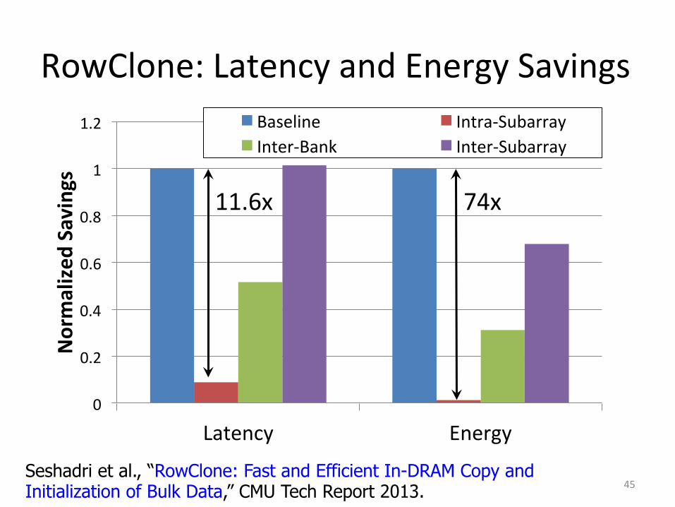
RowClone: Latency and Energy Savings
0
0.2
0.4
0.6
0.8
1
1.2
Latency Energy
Normalized
Savings
Baseline Intra-‐Subarray Inter-‐Bank Inter-‐Subarray
11.6x 74x
45 Seshadri et al., “RowClone: Fast and Efficient In-DRAM Copy and Initialization of Bulk Data,” CMU Tech Report 2013.

RowClone: Overall Performance
46

Goal: Ultra-efficient heterogeneous architectures
CPU core
CPU core
CPU core
CPU core
mini-CPU core
video core
GPU (throughput)
core
GPU (throughput)
core
GPU (throughput)
core
GPU (throughput)
core
LLC
Memory Controller Specialized
compute-capability in memory
Memory imaging core
Memory Bus
Slide credit: Prof. Kayvon Fatahalian, CMU

Enabling Ultra-efficient (Visual) Search
▪ What is the right partitioning of computation capability? ▪ What is the right low-cost memory substrate? ▪ What memory technologies are the best enablers? ▪ How do we rethink/ease (visual) search algorithms/applications?
Cache
Processor Core
Memory Bus
Main Memory
Database (of images)
Query vector
Results
Picture credit: Prof. Kayvon Fatahalian, CMU
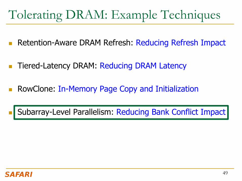
Tolerating DRAM: Example Techniques
n Retention-Aware DRAM Refresh: Reducing Refresh Impact n Tiered-Latency DRAM: Reducing DRAM Latency
n RowClone: In-Memory Page Copy and Initialization
n Subarray-Level Parallelism: Reducing Bank Conflict Impact
49

SALP: Reducing DRAM Bank Conflicts n Problem: Bank conflicts are costly for performance and energy
q serialized requests, wasted energy (thrashing of row buffer, busy wait)
n Goal: Reduce bank conflicts without adding more banks (low cost) n Key idea: Exploit the internal subarray structure of a DRAM bank to
parallelize bank conflicts to different subarrays q Slightly modify DRAM bank to reduce subarray-level hardware sharing
n Results on Server, Stream/Random, SPEC q 19% reduction in dynamic DRAM energy q 13% improvement in row hit rate q 17% performance improvement q 0.15% DRAM area overhead
50 Kim, Seshadri+ “A Case for Exploiting Subarray-Level Parallelism in DRAM,” ISCA 2012. 0.0
0.2
0.4
0.6
0.8
1.0
1.2
Nor
mal
ized
D
ynam
ic E
nerg
y
Baseline MASA
-19%
0%
20%
40%
60%
80%
100%
Row
-Buf
fer
Hit
-Rat
e
Baseline MASA
+13
%

Agenda
n Major Trends Affecting Main Memory n The DRAM Scaling Problem and Solution Directions
q Tolerating DRAM: New DRAM Architectures q Enabling Emerging Technologies: Hybrid Memory Systems
n How Can We Do Better? n Summary
51

Solution 2: Emerging Memory Technologies n Some emerging resistive memory technologies seem more
scalable than DRAM (and they are non-volatile)
n Example: Phase Change Memory q Data stored by changing phase of material q Data read by detecting material’s resistance q Expected to scale to 9nm (2022 [ITRS]) q Prototyped at 20nm (Raoux+, IBM JRD 2008) q Expected to be denser than DRAM: can store multiple bits/cell
n But, emerging technologies have (many) shortcomings q Can they be enabled to replace/augment/surpass DRAM?
52

Phase Change Memory: Pros and Cons n Pros over DRAM
q Better technology scaling (capacity and cost) q Non volatility q Low idle power (no refresh)
n Cons q Higher latencies: ~4-15x DRAM (especially write) q Higher active energy: ~2-50x DRAM (especially write) q Lower endurance (a cell dies after ~108 writes)
n Challenges in enabling PCM as DRAM replacement/helper: q Mitigate PCM shortcomings q Find the right way to place PCM in the system
53

PCM-based Main Memory (I) n How should PCM-based (main) memory be organized?
n Hybrid PCM+DRAM [Qureshi+ ISCA’09, Dhiman+ DAC’09]: q How to partition/migrate data between PCM and DRAM
54

PCM-based Main Memory (II) n How should PCM-based (main) memory be organized?
n Pure PCM main memory [Lee et al., ISCA’09, Top Picks’10]:
q How to redesign entire hierarchy (and cores) to overcome PCM shortcomings
55

An Initial Study: Replace DRAM with PCM n Lee, Ipek, Mutlu, Burger, “Architecting Phase Change
Memory as a Scalable DRAM Alternative,” ISCA 2009. q Surveyed prototypes from 2003-2008 (e.g. IEDM, VLSI, ISSCC) q Derived “average” PCM parameters for F=90nm
56
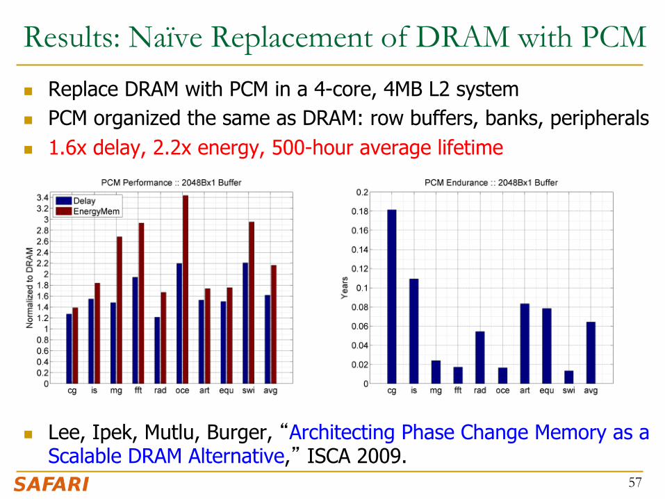
Results: Naïve Replacement of DRAM with PCM n Replace DRAM with PCM in a 4-core, 4MB L2 system n PCM organized the same as DRAM: row buffers, banks, peripherals n 1.6x delay, 2.2x energy, 500-hour average lifetime
n Lee, Ipek, Mutlu, Burger, “Architecting Phase Change Memory as a
Scalable DRAM Alternative,” ISCA 2009. 57
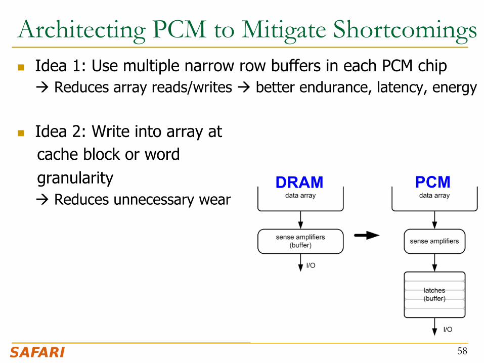
Architecting PCM to Mitigate Shortcomings n Idea 1: Use multiple narrow row buffers in each PCM chip
à Reduces array reads/writes à better endurance, latency, energy
n Idea 2: Write into array at cache block or word granularity
à Reduces unnecessary wear
58
DRAM PCM

Results: Architected PCM as Main Memory n 1.2x delay, 1.0x energy, 5.6-year average lifetime n Scaling improves energy, endurance, density
n Caveat 1: Worst-case lifetime is much shorter (no guarantees) n Caveat 2: Intensive applications see large performance and energy hits n Caveat 3: Optimistic PCM parameters?
59

Hybrid Memory Systems
Meza+, “Enabling Efficient and Scalable Hybrid Memories,” IEEE Comp. Arch. Letters, 2012. Yoon, Meza et al., “Row Buffer Locality Aware Caching Policies for Hybrid Memories,” ICCD 2012 Best Paper Award.
CPU DRAMCtrl
Fast, durable Small,
leaky, volatile, high-cost
Large, non-volatile, low-cost Slow, wears out, high active energy
PCM Ctrl DRAM Phase Change Memory (or Tech. X)
Hardware/software manage data allocation and movement to achieve the best of multiple technologies
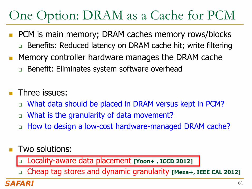
One Option: DRAM as a Cache for PCM n PCM is main memory; DRAM caches memory rows/blocks
q Benefits: Reduced latency on DRAM cache hit; write filtering
n Memory controller hardware manages the DRAM cache q Benefit: Eliminates system software overhead
n Three issues: q What data should be placed in DRAM versus kept in PCM? q What is the granularity of data movement? q How to design a low-cost hardware-managed DRAM cache?
n Two solutions: q Locality-aware data placement [Yoon+ , ICCD 2012]
q Cheap tag stores and dynamic granularity [Meza+, IEEE CAL 2012]
61

DRAM vs. PCM: An Observation n Row buffers are the same in DRAM and PCM n Row buffer hit latency same in DRAM and PCM n Row buffer miss latency small in DRAM, large in PCM
n Accessing the row buffer in PCM is fast n What incurs high latency is the PCM array access à avoid this
62
CPU DRAMCtrl
PCM Ctrl
Bank Bank Bank Bank
Row buffer DRAM Cache PCM Main Memory
N ns row hit Fast row miss
N ns row hit Slow row miss

Row-Locality-Aware Data Placement n Idea: Cache in DRAM only those rows that
q Frequently cause row buffer conflicts à because row-conflict latency is smaller in DRAM
q Are reused many times à to reduce cache pollution and bandwidth waste
n Simplified rule of thumb: q Streaming accesses: Better to place in PCM q Other accesses (with some reuse): Better to place in DRAM
n Yoon et al., “Row Buffer Locality-Aware Data Placement in Hybrid Memories,” ICCD 2012 Best Paper Award.
63
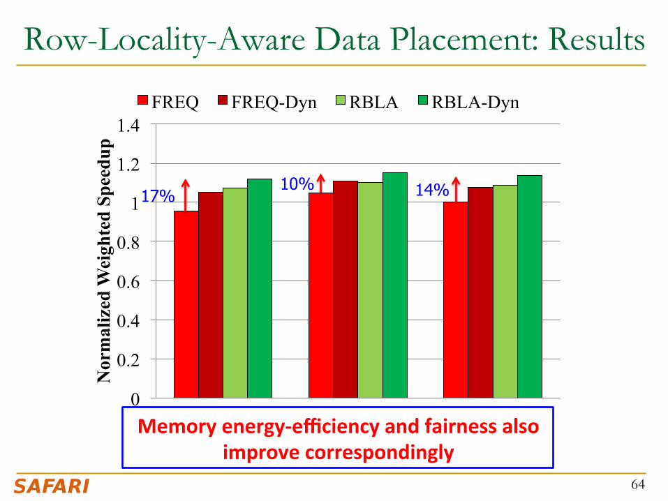
Row-Locality-Aware Data Placement: Results
64
0
0.2
0.4
0.6
0.8
1
1.2
1.4
Server Cloud Avg
Nor
mal
ized
Wei
ghte
d Sp
eedu
p
Workload
FREQ FREQ-Dyn RBLA RBLA-Dyn
10% 14% 17%
Memory energy-‐efficiency and fairness also improve correspondingly

0 0.2 0.4 0.6 0.8
1 1.2 1.4 1.6 1.8
2
Weighted Speedup Max. Slowdown Perf. per Watt Normalized Metric
16GB PCM RBLA-Dyn 16GB DRAM
0 0.2 0.4 0.6 0.8
1 1.2 1.4 1.6 1.8
2
Nor
mal
ized
Wei
ghte
d Sp
eedu
p
0
0.2
0.4
0.6
0.8
1
1.2
Nor
mal
ized
Max
. Slo
wdo
wn
Hybrid vs. All-PCM/DRAM
65
31% befer performance than all PCM, within 29% of all DRAM performance
31%
29%

Agenda
n Major Trends Affecting Main Memory n The DRAM Scaling Problem and Solution Directions
q Tolerating DRAM: New DRAM Architectures q Enabling Emerging Technologies: Hybrid Memory Systems
n How Can We Do Better? n Summary
66

Principles (So Far)
n Better cooperation between devices and the system q Expose more information about devices to upper layers q More flexible interfaces
n Better-than-worst-case design q Do not optimize for the worst case q Worst case should not determine the common case
n Heterogeneity in design q Enables a more efficient design (No one size fits all)
67

Other Opportunities with Emerging Technologies
n Merging of memory and storage q e.g., a single interface to manage all data
n New applications q e.g., ultra-fast checkpoint and restore
n More robust system design q e.g., reducing data loss
n Processing tightly-coupled with memory q e.g., enabling efficient search and filtering
68

Coordinated Memory and Storage with NVM (I) n The traditional two-level storage model is a bottleneck with NVM
q Volatile data in memory à a load/store interface q Persistent data in storage à a file system interface q Problem: Operating system (OS) and file system (FS) code to locate, translate,
buffer data become performance and energy bottlenecks with fast NVM stores
69
Two-Level Store
Processor and caches
Main Memory Storage (SSD/HDD)
Virtual memory
Address translation
Load/Store
Operating system
and file system
fopen, fread, fwrite, …

Coordinated Memory and Storage with NVM (II)
n Goal: Unify memory and storage management in a single unit to eliminate wasted work to locate, transfer, and translate data q Improves both energy and performance q Simplifies programming model as well
70
Unified Memory/Storage
Processor and caches
Persistent (e.g., Phase-Change) Memory
Load/Store
Persistent Memory Manager
Feedback
Meza+, “A Case for Efficient Hardware-Software Cooperative Management of Storage and Memory,” WEED 2013.

Performance Benefits of a Single-Level Store
71 Results for PostMark
0
0.2
0.4
0.6
0.8
1.0
HDD 2-level NVM 2-level Persistent Memory
Nor
mal
ized
Exe
cutio
n Ti
me
User CPU User Memory Syscall CPU Syscall I/O
0.0440.009
~5X

Energy Benefits of a Single-Level Store
72
0
0.2
0.4
0.6
0.8
1.0
HDD 2-level NVM 2-level Persistent Memory
Frac
tion
of T
otal
Ener
gy
User CPU Syscall CPU DRAM NVM HDD
0.0650.013
Results for PostMark
~5X

Agenda
n Major Trends Affecting Main Memory n The DRAM Scaling Problem and Solution Directions
q Tolerating DRAM: New DRAM Architectures q Enabling Emerging Technologies: Hybrid Memory Systems
n How Can We Do Better? n Summary
73

Summary: Main Memory Scaling n Main memory scaling problems are a critical bottleneck for
system performance, efficiency, and usability
n Solution 1: Tolerate DRAM with novel architectures q RAIDR: Retention-aware refresh q TL-DRAM: Tiered-Latency DRAM q RowClone: Fast page copy and initialization q SALP: Subarray-level parallelism
n Solution 2: Enable emerging memory technologies q Replace DRAM with NVM by architecting NVM chips well q Hybrid memory systems with automatic data management q Coordinated management of memory and storage
n Software/hardware/device cooperation essential for effective scaling of main memory
74

More Material: Slides, Papers, Videos
n These slides are a very short version of the Scalable Memory Systems course at ACACES 2013
n Website for Course Slides, Papers, and Videos q http://users.ece.cmu.edu/~omutlu/acaces2013-memory.html q http://users.ece.cmu.edu/~omutlu/projects.htm q Includes extended lecture notes and readings
n Overview Reading q Onur Mutlu,
"Memory Scaling: A Systems Architecture Perspective" Proceedings of the 5th International Memory Workshop (IMW), Monterey, CA, May 2013. Slides (pptx) (pdf)
75


Memory Scaling: A Systems Architecture Perspective
Onur Mutlu [email protected] August 6, 2013 MemCon 2013

Backup Slides
78

Backup Slides Agenda
n Building Large DRAM Caches for Hybrid Memories n Memory QoS and Predictable Performance n Subarray-Level Parallelism (SALP) in DRAM n Coordinated Memory and Storage with NVM
79

Building Large Caches for Hybrid Memories
80

One Option: DRAM as a Cache for PCM n PCM is main memory; DRAM caches memory rows/blocks
q Benefits: Reduced latency on DRAM cache hit; write filtering
n Memory controller hardware manages the DRAM cache q Benefit: Eliminates system software overhead
n Three issues: q What data should be placed in DRAM versus kept in PCM? q What is the granularity of data movement? q How to design a low-cost hardware-managed DRAM cache?
n Two ideas: q Locality-aware data placement [Yoon+ , ICCD 2012]
q Cheap tag stores and dynamic granularity [Meza+, IEEE CAL 2012]
81

The Problem with Large DRAM Caches n A large DRAM cache requires a large metadata (tag +
block-based information) store n How do we design an efficient DRAM cache?
82
DRAM PCM
CPU
(small, fast cache) (high capacity)
Mem Ctlr
Mem Ctlr
LOAD X
Access X
Metadata: X à DRAM
X

Idea 1: Store Tags in Main Memory n Store tags in the same row as data in DRAM
q Data and metadata can be accessed together
n Benefit: No on-chip tag storage overhead n Downsides:
q Cache hit determined only after a DRAM access q Cache hit requires two DRAM accesses
83
Cache block 2 Cache block 0 Cache block 1 DRAM row
Tag0 Tag1 Tag2

Idea 2: Cache Tags in On-Chip SRAM n Recall Idea 1: Store all metadata in DRAM
q To reduce metadata storage overhead
n Idea 2: Cache in on-chip SRAM frequently-accessed metadata q Cache only a small amount to keep SRAM size small
84
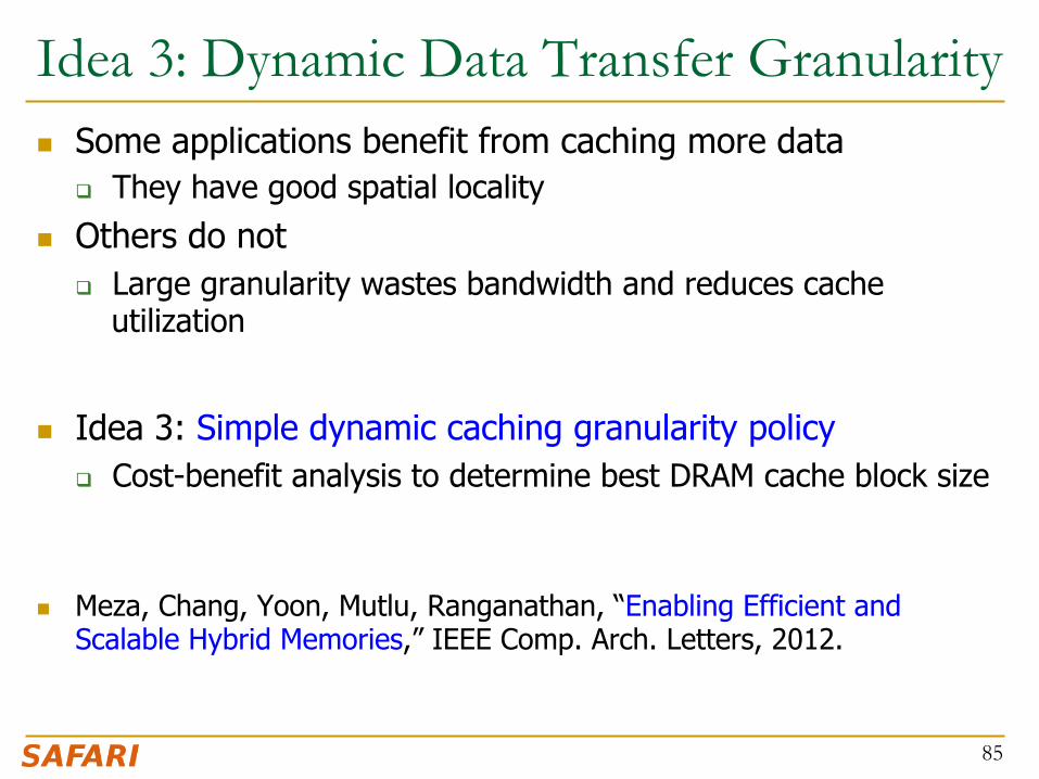
Idea 3: Dynamic Data Transfer Granularity n Some applications benefit from caching more data
q They have good spatial locality
n Others do not q Large granularity wastes bandwidth and reduces cache
utilization
n Idea 3: Simple dynamic caching granularity policy q Cost-benefit analysis to determine best DRAM cache block size
n Meza, Chang, Yoon, Mutlu, Ranganathan, “Enabling Efficient and Scalable Hybrid Memories,” IEEE Comp. Arch. Letters, 2012.
85

0
0.1
0.2
0.3
0.4
0.5
0.6
0.7
0.8
0.9
1
SRAM Region TIM TIMBER TIMBER-‐Dyn
Normalized
Weighted Speedu
p
86
TIMBER Performance
-‐6%
Meza, Chang, Yoon, Mutlu, Ranganathan, “Enabling Efficient and Scalable Hybrid Memories,” IEEE Comp. Arch. Legers, 2012.
0
0.2
0.4
0.6
0.8
1
1.2
SRAM Region TIM TIMBER TIMBER-‐Dyn
Normalized
Perform
ance per W
af
(for M
emory System
)
87
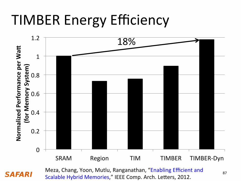
TIMBER Energy Efficiency 18%
Meza, Chang, Yoon, Mutlu, Ranganathan, “Enabling Efficient and Scalable Hybrid Memories,” IEEE Comp. Arch. Legers, 2012.
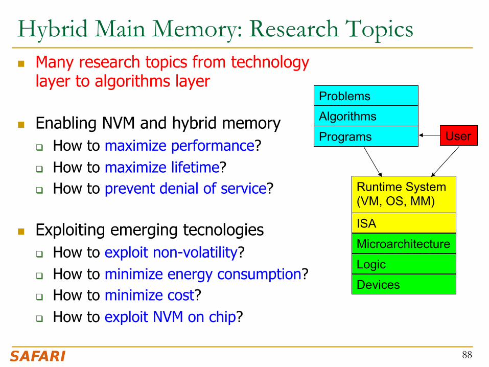
Hybrid Main Memory: Research Topics n Many research topics from technology
layer to algorithms layer
n Enabling NVM and hybrid memory q How to maximize performance? q How to maximize lifetime? q How to prevent denial of service?
n Exploiting emerging tecnologies q How to exploit non-volatility? q How to minimize energy consumption? q How to minimize cost? q How to exploit NVM on chip?
88
Microarchitecture
ISA
Programs
Algorithms Problems
Logic
Devices
Runtime System (VM, OS, MM)
User

Security Challenges of Emerging Technologies
1. Limited endurance à Wearout attacks 2. Non-volatility à Data persists in memory after powerdown à Easy retrieval of privileged or private information 3. Multiple bits per cell à Information leakage (via side channel)
89

Memory QoS
90

Trend: Many Cores on Chip n Simpler and lower power than a single large core n Large scale parallelism on chip
91
IBM Cell BE 8+1 cores
Intel Core i7 8 cores
Tilera TILE Gx 100 cores, networked
IBM POWER7 8 cores
Intel SCC 48 cores, networked
Nvidia Fermi 448 “cores”
AMD Barcelona 4 cores
Sun Niagara II 8 cores
Many Cores on Chip
n What we want: q N times the system performance with N times the cores
n What do we get today?
92
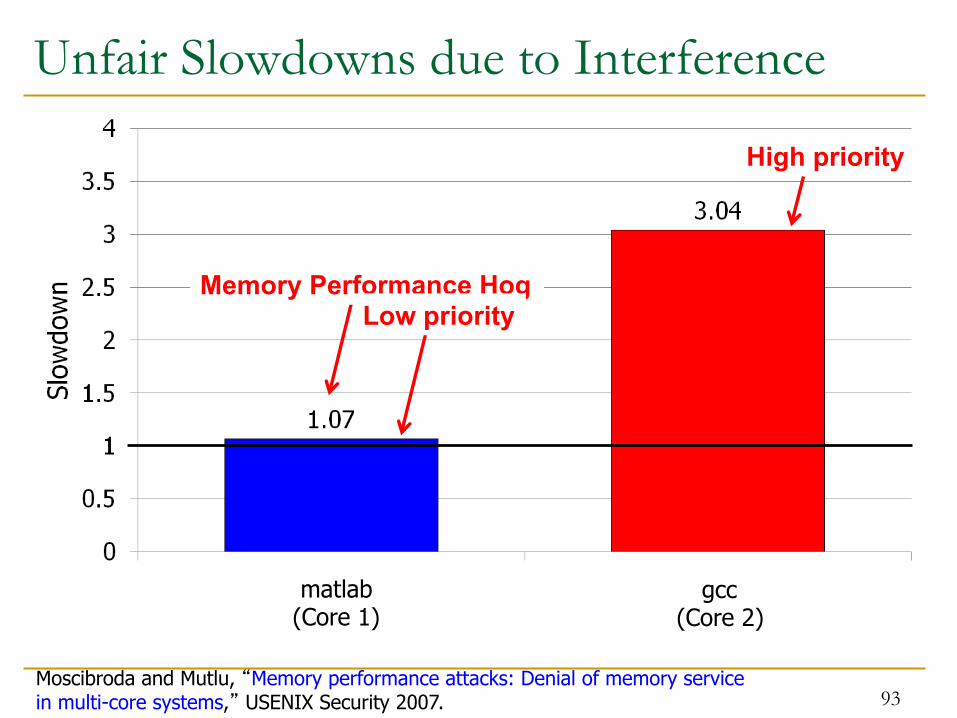
Unfair Slowdowns due to Interference
Memory Performance Hog Low priority
High priority
(Core 0) (Core 1)
Moscibroda and Mutlu, “Memory performance attacks: Denial of memory service in multi-core systems,” USENIX Security 2007.
matlab (Core 1)
gcc (Core 2)
93
94
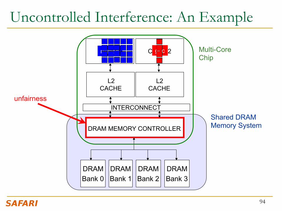
Uncontrolled Interference: An Example
CORE 1 CORE 2
L2 CACHE
L2 CACHE
DRAM MEMORY CONTROLLER
DRAM Bank 0
DRAM Bank 1
DRAM Bank 2
Shared DRAM Memory System
Multi-Core Chip
unfairness INTERCONNECT
matlab gcc
DRAM Bank 3

// initialize large arrays A, B for (j=0; j<N; j++) { index = rand(); A[index] = B[index]; … }
95
A Memory Performance Hog
STREAM
- Sequential memory access - Very high row buffer locality (96% hit rate) - Memory intensive
RANDOM
- Random memory access - Very low row buffer locality (3% hit rate) - Similarly memory intensive
// initialize large arrays A, B for (j=0; j<N; j++) { index = j*linesize; A[index] = B[index]; … }
streaming random
Moscibroda and Mutlu, “Memory Performance Attacks,” USENIX Security 2007.

96
What Does the Memory Hog Do?
Row Buffer
Row
dec
oder
Column mux
Data
Row 0
T0: Row 0
Row 0
T1: Row 16 T0: Row 0 T1: Row 111
T0: Row 0 T0: Row 0 T1: Row 5
T0: Row 0 T0: Row 0 T0: Row 0 T0: Row 0 T0: Row 0
Memory Request Buffer
T0: STREAM T1: RANDOM
Row size: 8KB, cache block size: 64B 128 (8KB/64B) requests of T0 serviced before T1
Moscibroda and Mutlu, “Memory Performance Attacks,” USENIX Security 2007.

Effect of the Memory Performance Hog
0
0.5
1
1.5
2
2.5
3
STREAM RANDOM
97
1.18X slowdown
2.82X slowdown
Results on Intel Pentium D running Windows XP (Similar results for Intel Core Duo and AMD Turion, and on Fedora Linux)
Slow
dow
n
0
0.5
1
1.5
2
2.5
3
STREAM gcc 0
0.5
1
1.5
2
2.5
3
STREAM Virtual PC
Moscibroda and Mutlu, “Memory Performance Attacks,” USENIX Security 2007.

Greater Problem with More Cores
n Vulnerable to denial of service (DoS)
n Unable to enforce priorities or SLAs n Low system performance
Uncontrollable, unpredictable system
98

Distributed DoS in Networked Multi-Core Systems
99
Attackers (Cores 1-8)
Stock option pricing application (Cores 9-64)
Cores connected via packet-switched routers on chip
~5000X slowdown
Grot, Hestness, Keckler, Mutlu, “Preemptive virtual clock: A Flexible, Efficient, and Cost-effective QOS Scheme for Networks-on-Chip,“ MICRO 2009.

How Do We Solve The Problem?
n Inter-thread interference is uncontrolled in all memory resources q Memory controller q Interconnect q Caches
n We need to control it q i.e., design an interference-aware (QoS-aware) memory system
100

QoS-Aware Memory Systems: Challenges
n How do we reduce inter-thread interference? q Improve system performance and core utilization q Reduce request serialization and core starvation
n How do we control inter-thread interference? q Provide mechanisms to enable system software to enforce
QoS policies q While providing high system performance
n How do we make the memory system configurable/flexible? q Enable flexible mechanisms that can achieve many goals
n Provide fairness or throughput when needed n Satisfy performance guarantees when needed
101

Designing QoS-Aware Memory Systems: Approaches
n Smart resources: Design each shared resource to have a configurable interference control/reduction mechanism q QoS-aware memory controllers [Mutlu+ MICRO’07] [Moscibroda+, Usenix Security’07]
[Mutlu+ ISCA’08, Top Picks’09] [Kim+ HPCA’10] [Kim+ MICRO’10, Top Picks’11] [Ebrahimi+ ISCA’11, MICRO’11] [Ausavarungnirun+, ISCA’12]
q QoS-aware interconnects [Das+ MICRO’09, ISCA’10, Top Picks ’11] [Grot+ MICRO’09, ISCA’11, Top Picks ’12]
q QoS-aware caches
n Dumb resources: Keep each resource free-for-all, but reduce/control interference by injection control or data mapping q Source throttling to control access to memory system [Ebrahimi+ ASPLOS’10,
ISCA’11, TOCS’12] [Ebrahimi+ MICRO’09] [Nychis+ HotNets’10]
q QoS-aware data mapping to memory controllers [Muralidhara+ MICRO’11]
q QoS-aware thread scheduling to cores
102

n Memory Channel Partitioning q Idea: System software maps badly-interfering applications’ pages
to different channels [Muralidhara+, MICRO’11]
n Separate data of low/high intensity and low/high row-locality applications n Especially effective in reducing interference of threads with “medium” and
“heavy” memory intensity q 11% higher performance over existing systems (200 workloads)
A Mechanism to Reduce Memory Interference
103
Core 0 App A
Core 1 App B
Channel 0
Bank 1
Channel 1
Bank 0
Bank 1
Bank 0
Conventional Page Mapping
Time Units
1 2 3 4 5
Channel Partitioning
Core 0 App A
Core 1 App B
Channel 0
Bank 1
Bank 0
Bank 1
Bank 0
Time Units
1 2 3 4 5
Channel 1

Designing QoS-Aware Memory Systems: Approaches
n Smart resources: Design each shared resource to have a configurable interference control/reduction mechanism q QoS-aware memory controllers [Mutlu+ MICRO’07] [Moscibroda+, Usenix Security’07]
[Mutlu+ ISCA’08, Top Picks’09] [Kim+ HPCA’10] [Kim+ MICRO’10, Top Picks’11] [Ebrahimi+ ISCA’11, MICRO’11] [Ausavarungnirun+, ISCA’12][Subramanian+, HPCA’13]
q QoS-aware interconnects [Das+ MICRO’09, ISCA’10, Top Picks ’11] [Grot+ MICRO’09, ISCA’11, Top Picks ’12]
q QoS-aware caches
n Dumb resources: Keep each resource free-for-all, but reduce/control interference by injection control or data mapping q Source throttling to control access to memory system [Ebrahimi+ ASPLOS’10,
ISCA’11, TOCS’12] [Ebrahimi+ MICRO’09] [Nychis+ HotNets’10] [Nychis+ SIGCOMM’12]
q QoS-aware data mapping to memory controllers [Muralidhara+ MICRO’11]
q QoS-aware thread scheduling to cores [Das+ HPCA’13]
104

QoS-Aware Memory Scheduling
n How to schedule requests to provide q High system performance q High fairness to applications q Configurability to system software
n Memory controller needs to be aware of threads
105
Memory Controller
Core Core
Core Core Memory
Resolves memory contention by scheduling requests

QoS-Aware Memory Scheduling: Evolution n Stall-time fair memory scheduling [Mutlu+ MICRO’07]
q Idea: Estimate and balance thread slowdowns
q Takeaway: Proportional thread progress improves performance, especially when threads are “heavy” (memory intensive)
n Parallelism-aware batch scheduling [Mutlu+ ISCA’08, Top Picks’09]
q Idea: Rank threads and service in rank order (to preserve bank parallelism); batch requests to prevent starvation
q Takeaway: Preserving within-thread bank-parallelism improves performance; request batching improves fairness
n ATLAS memory scheduler [Kim+ HPCA’10]
q Idea: Prioritize threads that have attained the least service from the memory scheduler
q Takeaway: Prioritizing “light” threads improves performance 106

Take turns accessing memory
Throughput vs. Fairness
107
Fairness biased approach
thread C
thread B
thread A
less memory intensive
higher priority
PrioriIze less memory-‐intensive threads
Throughput biased approach
Good for throughput
starvaGon è unfairness
thread C thread B thread A
Does not starve
not prioriGzed è reduced throughput
Single policy for all threads is insufficient

Achieving the Best of Both Worlds
108
thread
thread
higher priority
thread
thread
thread
thread
thread
thread
PrioriQze memory-‐non-‐intensive threads
For Throughput
Unfairness caused by memory-‐intensive being prioriQzed over each other
• Shuffle thread ranking
Memory-‐intensive threads have different vulnerability to interference
• Shuffle asymmetrically
For Fairness
thread
thread
thread
thread

Thread Cluster Memory Scheduling [Kim+ MICRO’10]
1. Group threads into two clusters 2. PrioriQze non-‐intensive cluster 3. Different policies for each cluster
109
thread
Threads in the system
thread
thread
thread
thread
thread
thread
Non-‐intensive cluster
Intensive cluster
thread
thread
thread
Memory-‐non-‐intensive
Memory-‐intensive
PrioriGzed
higher priority
higher priority
Throughput
Fairness Kim+, “Thread Cluster Memory Scheduling,” MICRO 2010.

TCM: Quantum-Based Operation
110
Time
Previous quantum (~1M cycles)
During quantum: • Monitor thread behavior 1. Memory intensity 2. Bank-‐level parallelism 3. Row-‐buffer locality
Beginning of quantum: • Perform clustering • Compute niceness of intensive threads
Current quantum (~1M cycles)
Shuffle interval (~1K cycles)
Kim+, “Thread Cluster Memory Scheduling,” MICRO 2010.

TCM: Throughput and Fairness
FRFCFS
STFM
PAR-‐BS
ATLAS
TCM
4
6
8
10
12
14
16
7.5 8 8.5 9 9.5 10
Maxim
um Slowdo
wn
Weighted Speedup
111
Beger system throughput
Beger fa
irness
24 cores, 4 memory controllers, 96 workloads
TCM, a heterogeneous scheduling policy, provides best fairness and system throughput
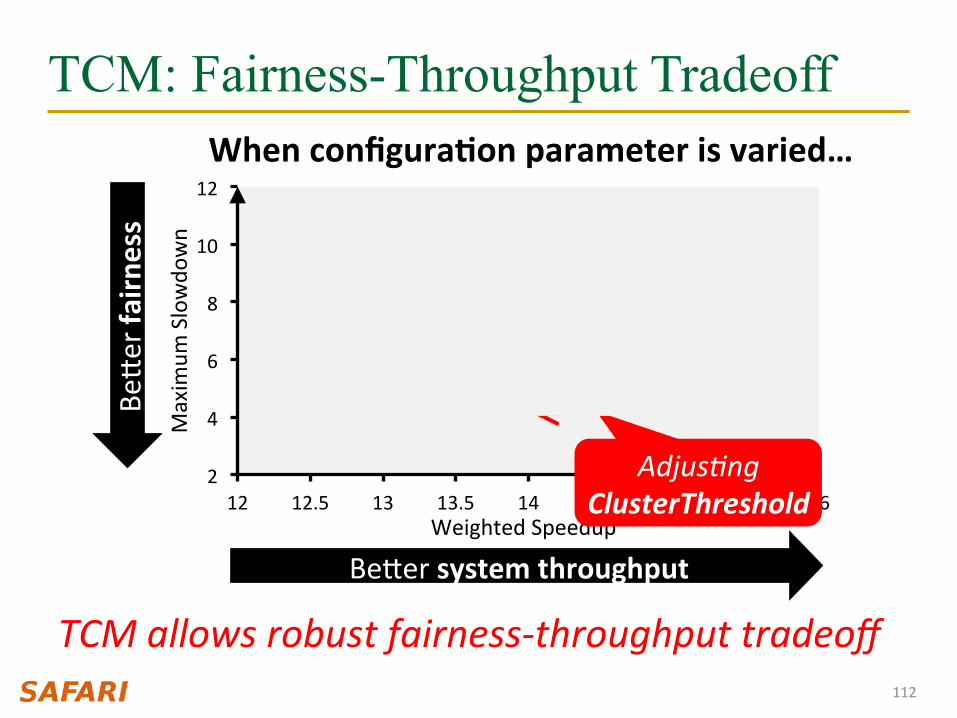
TCM: Fairness-Throughput Tradeoff
112
2
4
6
8
10
12
12 12.5 13 13.5 14 14.5 15 15.5 16
Maxim
um Slowdo
wn
Weighted Speedup
When configuraQon parameter is varied…
Adjus.ng ClusterThreshold
TCM allows robust fairness-‐throughput tradeoff
STFM PAR-‐BS
ATLAS
TCM
Beger system throughput
Beger fa
irness FRFCFS

More on TCM
n Yoongu Kim, Michael Papamichael, Onur Mutlu, and Mor Harchol-Balter, "Thread Cluster Memory Scheduling: Exploiting Differences in Memory Access Behavior" Proceedings of the 43rd International Symposium on Microarchitecture (MICRO), pages 65-76, Atlanta, GA, December 2010. Slides (pptx) (pdf)
113

Memory Control in CPU-GPU Systems n Observation: Heterogeneous CPU-GPU systems require
memory schedulers with large request buffers
n Problem: Existing monolithic application-aware memory scheduler designs are hard to scale to large request buffer sizes
n Solution: Staged Memory Scheduling (SMS) decomposes the memory controller into three simple stages: 1) Batch formation: maintains row buffer locality 2) Batch scheduler: reduces interference between applications 3) DRAM command scheduler: issues requests to DRAM
n Compared to state-of-the-art memory schedulers: q SMS is significantly simpler and more scalable q SMS provides higher performance and fairness
114 Ausavarungnirun+, “Staged Memory Scheduling,” ISCA 2012.

Key Idea: Decouple Tasks into Stages n Idea: Decouple the functional tasks of the memory controller
q Partition tasks across several simpler HW structures (stages)
1) Maximize row buffer hits q Stage 1: Batch formation q Within each application, groups requests to the same row into
batches
2) Manage contention between applications q Stage 2: Batch scheduler q Schedules batches from different applications
3) Satisfy DRAM timing constraints q Stage 3: DRAM command scheduler q Issues requests from the already-scheduled order to each bank
115

SMS: Staged Memory Scheduling
116
Memory Scheduler
Core 1 Core 2 Core 3 Core 4
To DRAM
GPU
Req Req
Req
Req Req
Req Req Req Req Req
Req Req Req Req Req
Req Req
Req Req Req
Req Req Req
Req
Req
Req Req
Req Req Req Req Req
Req Req Req Req Req Req Req
Req
Req Req Batch Scheduler
Stage 1
Stage 2
Stage 3
Req
Mon
olith
ic S
ched
uler
Batch Formation
DRAM Command Scheduler
Bank 1 Bank 2 Bank 3 Bank 4

Stage 1
Stage 2
SMS: Staged Memory Scheduling
117
Core 1 Core 2 Core 3 Core 4
To DRAM
GPU
Req Req Batch Scheduler
Batch Formation
Stage 3
DRAM Command Scheduler
Bank 1 Bank 2 Bank 3 Bank 4

Current Batch Scheduling
Policy SJF
Current Batch Scheduling
Policy RR
Batch Scheduler
Bank 1 Bank 2 Bank 3 Bank 4
SMS: Staged Memory Scheduling
118
Core 1 Core 2 Core 3 Core 4
Stage 1: Batch Formation
Stage 3: DRAM Command Scheduler
GPU
Stage 2:
Ausavarungnirun+, “Staged Memory Scheduling,” ISCA 2012.

SMS Complexity n Compared to a row hit first scheduler, SMS consumes*
q 66% less area q 46% less static power
n Reduction comes from: q Monolithic scheduler à stages of simpler schedulers q Each stage has a simpler scheduler (considers fewer
properties at a time to make the scheduling decision) q Each stage has simpler buffers (FIFO instead of out-of-order) q Each stage has a portion of the total buffer size (buffering is
distributed across stages)
119 * Based on a Verilog model using 180nm library

SMS Performance
120
0
0.2
0.4
0.6
0.8
1
0.001 0.1 10 1000
Syst
em P
erfo
rman
ce
GPUweight
Previous Best Best Previous Scheduler
ATLAS TCM FR-FCFS

n At every GPU weight, SMS outperforms the best previous scheduling algorithm for that weight
SMS Performance
121
0
0.2
0.4
0.6
0.8
1
0.001 0.1 10 1000
Syst
em P
erfo
rman
ce
GPUweight
Previous Best
SMS SMS
Best Previous Scheduler

CPU-GPU Performance Tradeoff
122
0 10 20 30 40 50 60 70 80 90
1 0.5 0.1 0.05 0
Fram
e R
ate
SJF Probability
GPU Frame Rate
0
1
2
3
4
5
6
1 0.5 0.1 0.05 0
Wei
ghte
d Sp
eedu
p
SJF Probability
CPU Performance

More on SMS
n Rachata Ausavarungnirun, Kevin Chang, Lavanya Subramanian, Gabriel Loh, and Onur Mutlu, "Staged Memory Scheduling: Achieving High Performance and Scalability in Heterogeneous Systems" Proceedings of the 39th International Symposium on Computer Architecture (ISCA), Portland, OR, June 2012. Slides (pptx)
123

Stronger Memory Service Guarantees [HPCA’13] n Uncontrolled memory interference slows down
applications unpredictably n Goal: Estimate and control slowdowns
n MISE: An accurate slowdown estimation model q Request Service Rate is a good proxy for performance
n Slowdown = Request Service Rate Alone / Request Service Rate Shared q Request Service Rate Alone estimated by giving an application highest
priority in accessing memory q Average slowdown estimation error of MISE: 8.2% (3000 data pts)
n Memory controller leverages MISE to control slowdowns q To provide soft slowdown guarantees q To minimize maximum slowdown
124 Subramanian+, “MISE,” HPCA 2013.
More on MISE
n Lavanya Subramanian, Vivek Seshadri, Yoongu Kim, Ben Jaiyen, and Onur Mutlu, "MISE: Providing Performance Predictability and Improving Fairness in Shared Main Memory Systems" Proceedings of the 19th International Symposium on High-Performance Computer Architecture (HPCA), Shenzhen, China, February 2013. Slides (pptx)
125

Memory QoS in a Parallel Application
n Threads in a multithreaded application are inter-dependent n Some threads can be on the critical path of execution due
to synchronization; some threads are not n How do we schedule requests of inter-dependent threads to
maximize multithreaded application performance?
n Idea: Estimate limiter threads likely to be on the critical path and prioritize their requests; shuffle priorities of non-limiter threads to reduce memory interference among them [Ebrahimi+, MICRO’11]
n Hardware/software cooperative limiter thread estimation: n Thread executing the most contended critical section n Thread that is falling behind the most in a parallel for loop
126 Ebrahimi+, “Parallel Application Memory Scheduling,” MICRO 2011.

More on PAMS
n Eiman Ebrahimi, Rustam Miftakhutdinov, Chris Fallin, Chang Joo Lee, Onur Mutlu, and Yale N. Patt, "Parallel Application Memory Scheduling" Proceedings of the 44th International Symposium on Microarchitecture (MICRO), Porto Alegre, Brazil, December 2011. Slides (pptx)
127

Summary: Memory QoS Approaches and Techniques
n Approaches: Smart vs. dumb resources q Smart resources: QoS-aware memory scheduling q Dumb resources: Source throttling; channel partitioning q Both approaches are effective in reducing interference q No single best approach for all workloads
n Techniques: Request scheduling, source throttling, memory partitioning q All approaches are effective in reducing interference q Can be applied at different levels: hardware vs. software q No single best technique for all workloads
n Combined approaches and techniques are the most powerful q Integrated Memory Channel Partitioning and Scheduling [MICRO’11]
128

SALP: Reducing DRAM Bank Conflict Impact
129
Kim, Seshadri, Lee, Liu, Mutlu A Case for Exploiting Subarray-Level Parallelism (SALP) in DRAM ISCA 2012.

SALP: Reducing DRAM Bank Conflicts n Problem: Bank conflicts are costly for performance and energy
q serialized requests, wasted energy (thrashing of row buffer, busy wait)
n Goal: Reduce bank conflicts without adding more banks (low cost) n Key idea: Exploit the internal subarray structure of a DRAM bank to
parallelize bank conflicts to different subarrays q Slightly modify DRAM bank to reduce subarray-level hardware sharing
130 Kim, Seshadri+ “A Case for Exploiting Subarray-Level Parallelism in DRAM,” ISCA 2012.
-19%
+13
%

SALP: Key Ideas
n A DRAM bank consists of mostly-independent subarrays q Subarrays share some global structures to reduce cost
131
Key Idea of SALP: Minimally reduce sharing of global structures
Reduce the sharing of … Global decoder à Enables pipelined access to subarrays Global row buffer à Utilizes multiple local row buffers

SALP: Reduce Sharing of Global Decoder
132
Local row-buffer
Local row-buffer Global row-buffer
···
Glob
al Decod
er
Latch
Latch
Latch
Instead of a global latch, have per-subarray latches

SALP: Reduce Sharing of Global Row-Buffer
133
Wir
e
Global bitlines
Global row-buffer
Local row-buffer
Local row-buffer
Switch
Switch
READ READ
DD
DD
Selectively connect local row-buffers to global row-buffer using a Designated single-bit latch

SALP: Baseline Bank Organization
134
Local row-buffer
Local row-buffer
Global row-buffer
Glob
al Decod
er
Global bitlines
Latch

SALP: Proposed Bank Organization
135
Local row-buffer
Local row-buffer
Global row-buffer
Glob
al Decod
er
Latch
Latch
D
D
Global bitlines
Overhead of SALP in DRAM chip: 0.15% 1. Global latch à per-subarray local latches 2. Designated bit latches and wire to selectively enable a subarray

SALP: Results n Wide variety of systems with different #channels, banks,
ranks, subarrays n Server, streaming, random-access, SPEC workloads
n Dynamic DRAM energy reduction: 19% q DRAM row hit rate improvement: 13%
n System performance improvement: 17% q Within 3% of ideal (all independent banks)
n DRAM die area overhead: 0.15% q vs. 36% overhead of independent banks
136

More on SALP
n Yoongu Kim, Vivek Seshadri, Donghyuk Lee, Jamie Liu, and Onur Mutlu, "A Case for Exploiting Subarray-Level Parallelism (SALP) in DRAM" Proceedings of the 39th International Symposium on Computer Architecture (ISCA), Portland, OR, June 2012. Slides (pptx)
137

Coordinated Memory and Storage with NVM
138
Meza, Luo, Khan, Zhao, Xie, and Mutlu, "A Case for Efficient Hardware-Software Cooperative Management of Storage and Memory” WEED 2013.

Overview n Traditional systems have a two-level storage model
q Access volatile data in memory with a load/store interface q Access persistent data in storage with a file system interface q Problem: Operating system (OS) and file system (FS) code and buffering
for storage lead to energy and performance inefficiencies
n Opportunity: New non-volatile memory (NVM) technologies can help provide fast (similar to DRAM), persistent storage (similar to Flash) q Unfortunately, OS and FS code can easily become energy efficiency and
performance bottlenecks if we keep the traditional storage model
n This work: makes a case for hardware/software cooperative management of storage and memory within a single-level q We describe the idea of a Persistent Memory Manager (PMM) for
efficiently coordinating storage and memory, and quantify its benefit q And, examine questions and challenges to address to realize PMM
139
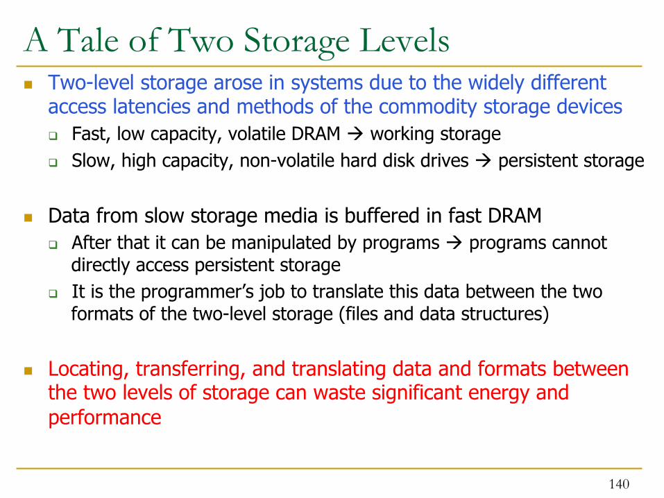
A Tale of Two Storage Levels n Two-level storage arose in systems due to the widely different
access latencies and methods of the commodity storage devices q Fast, low capacity, volatile DRAM à working storage q Slow, high capacity, non-volatile hard disk drives à persistent storage
n Data from slow storage media is buffered in fast DRAM q After that it can be manipulated by programs à programs cannot
directly access persistent storage q It is the programmer’s job to translate this data between the two
formats of the two-level storage (files and data structures)
n Locating, transferring, and translating data and formats between the two levels of storage can waste significant energy and performance
140

Opportunity: New Non-Volatile Memories n Emerging memory technologies provide the potential for unifying
storage and memory (e.g., Phase-Change, STT-RAM, RRAM) q Byte-addressable (can be accessed like DRAM) q Low latency (comparable to DRAM) q Low power (idle power better than DRAM) q High capacity (closer to Flash) q Non-volatile (can enable persistent storage) q May have limited endurance (but, better than Flash)
n Can provide fast access to both volatile data and persistent storage
n Question: if such devices are used, is it efficient to keep a two-level storage model?
141

Eliminating Traditional Storage Bottlenecks
142
Normalized Total Energy
0
0.2
0.4
0.6
0.8
1.0
HDD Baseline NVM Baseline Persistent Memory
Frac
tion
of T
otal
Ene
rgy
0.0650.013
Today (DRAM + HDD) and two-level storage model Replace HDD
with NVM (PCM-like),
keep two-level storage model
Replace HDD and DRAM with NVM
(PCM-like), eliminate all
OS+FS overhead
Results for PostMark
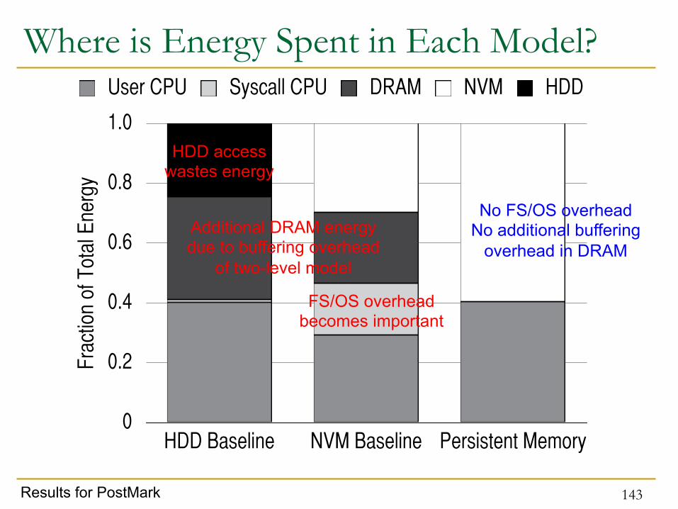
Where is Energy Spent in Each Model?
143
0
0.2
0.4
0.6
0.8
1.0
HDD Baseline NVM Baseline Persistent Memory
Frac
tion
of T
otal
Ene
rgy
User CPU Syscall CPU DRAM NVM HDD
HDD access wastes energy
FS/OS overhead becomes important
Additional DRAM energy due to buffering overhead
of two-level model
No FS/OS overhead No additional buffering
overhead in DRAM
Results for PostMark

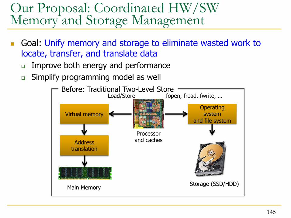
Our Proposal: Coordinated HW/SW Memory and Storage Management
n Goal: Unify memory and storage to eliminate wasted work to locate, transfer, and translate data q Improve both energy and performance q Simplify programming model as well
144
Our Proposal: Coordinated HW/SW Memory and Storage Management
n Goal: Unify memory and storage to eliminate wasted work to locate, transfer, and translate data q Improve both energy and performance q Simplify programming model as well
145
Before: Traditional Two-Level Store
Processor and caches
Main Memory Storage (SSD/HDD)
Virtual memory
Address translation
Load/Store
Operating system
and file system
fopen, fread, fwrite, …

Our Proposal: Coordinated HW/SW Memory and Storage Management
n Goal: Unify memory and storage to eliminate wasted work to locate, transfer, and translate data q Improve both energy and performance q Simplify programming model as well
146
After: Coordinated HW/SW Management
Processor and caches
Persistent (e.g., Phase-Change) Memory
Load/Store
Persistent Memory Manager
Feedback

The Persistent Memory Manager (PMM) n Exposes a load/store interface to access persistent data
q Applications can directly access persistent memory à no conversion, translation, location overhead for persistent data
n Manages data placement, location, persistence, security q To get the best of multiple forms of storage
n Manages metadata storage and retrieval q This can lead to overheads that need to be managed
n Exposes hooks and interfaces for system software q To enable better data placement and management decisions
147
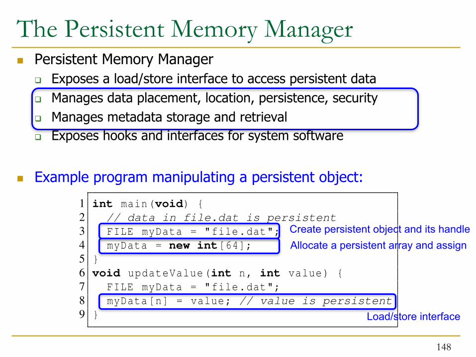
The Persistent Memory Manager n Persistent Memory Manager
q Exposes a load/store interface to access persistent data q Manages data placement, location, persistence, security q Manages metadata storage and retrieval q Exposes hooks and interfaces for system software
n Example program manipulating a persistent object:
148
2.2.1 Efficient Hardware and Software Support: We propose to investigate the efficient software andhardware support needed for single-level stores. A single-level store system should provide an abstractionthat maps persistent user data to physical addresses in memory. A software interface for programs wouldmap a pointer to the actual persistent data. Programs would be able to access any part of the data usingnormal load and store instructions. Figure 2 shows two examples of high-level abstractions which couldbe provided to programs to access persistent data in a single-level store system. In it, a program createsa persistent file (Figure 2 left) or object (Figure 2 right) using the handle “file.dat” and allocates an arrayof integers in it. Later—perhaps after the application or system is restarted—when the program executesthe updateValue() function, the system retrieves the persistent data for the same handle, and the programmodifies its state. With such an abstraction, a single-level store can eliminate the OS system calls to transferdata to and from disk. In addition, it eliminates the need for a file system to track physical file addressesby traversing metadata (such as inodes) in the OS. In this way, single-level stores provide the opportunity todesign a simple and efficient persistent data lookup system in hardware. We plan to research efficient waysto map files or objects to the virtual address space. In such a hardware-based design, the processor wouldmanage how data handles correspond to physical addresses. Note that, single-level stores can use alternativedesign choices, such as segments, to provide the high-level abstraction instead of files or objects. Regardless,segments, files, or objects will be mapped to physical addresses with hardware support. Prior works tried tomake file lookup and update efficient in software [27, 28] in the presence of persistent memory, and otherworks proposed using complex and potentially inefficient hardware directory techniques (e.g., [15]). Ourgoal is to design fast and efficient techniques that take into account the byte addressability of persistentmemory in a single-level store. To this end, we will research the following:• The efficient use of hash table and B-tree indices for locating files in a single-level store.• How techniques such as key-value stores can provide fast and efficient lookups in single-level stores.• Policies for intelligently caching some entries of these indices in hardware to improve system perfor-
mance.Every access in the single-level store needs to be translated from a virtual address used by a program to
a physical address used to access a device. We will investigate how to efficiently manage address translationso that locating data is simple and fast. We intend to explore the following directions to solve this problem:• We will design mechanisms to predict access patterns based on program behavior and pre-compute
virtual-to-physical address translations. We are interested in answering questions such as: What is thepattern of data accesses to a single-level store, and how can prefetching techniques be redesigned withsingle-level stores in mind to enable efficient address translation? How can simple application-level orprofile-based hints on access patterns be communicated to and used by hardware to make address translationand prefetching efficient?• We will design efficient translation lookaside buffer (TLB)-like structures which will cache the trans-
lation between virtual and physical addresses but for a much larger amount of physical memory than inexisting systems. In the presence of such a single-level store, many disparate data accesses could need alarge translation table to be serviced effectively. To reduce overhead of such hardware, we are interested inexploring whether TLB-like structures should favor storing translations only for particular classes of data,such as data with locality or data which is on the critical path of execution, which get the most benefitout of the limited structure space. In addition, we will investigate centralized versus distributed translationstructures to design techniques that, for example, buffer private data translation entries near the processor,while distributing shared entries across processors to minimize translation overheads. Such translation struc-
1 int main(void) {2 // data in file.dat is persistent3 FILE myData = "file.dat";4 myData = new int[64];5 }6 void updateValue(int n, int value) {7 FILE myData = "file.dat";8 myData[n] = value; // value is persistent9 }
1 int main(void) {2 // data in file.dat is persistent3 int *myData = new PersistentObject("file.dat");4 myData = new int[64];5 }6 void updateValue(int n, int value) {7 int *myData = PersistentObject.open("file.dat");8 myData[n] = value; // value is persistent9 }
Figure 2: Sample program with access to file-based (left) and object-based (right) persistent data.
5
Create persistent object and its handle Allocate a persistent array and assign
Load/store interface

Putting Everything Together
149
2.2.1 Efficient Hardware and Software Support: We propose to investigate the efficient software andhardware support needed for single-level stores. A single-level store system should provide an abstractionthat maps persistent user data to physical addresses in memory. A software interface for programs wouldmap a pointer to the actual persistent data. Programs would be able to access any part of the data usingnormal load and store instructions. Figure 2 shows two examples of high-level abstractions which couldbe provided to programs to access persistent data in a single-level store system. In it, a program createsa persistent file (Figure 2 left) or object (Figure 2 right) using the handle “file.dat” and allocates an arrayof integers in it. Later—perhaps after the application or system is restarted—when the program executesthe updateValue() function, the system retrieves the persistent data for the same handle, and the programmodifies its state. With such an abstraction, a single-level store can eliminate the OS system calls to transferdata to and from disk. In addition, it eliminates the need for a file system to track physical file addressesby traversing metadata (such as inodes) in the OS. In this way, single-level stores provide the opportunity todesign a simple and efficient persistent data lookup system in hardware. We plan to research efficient waysto map files or objects to the virtual address space. In such a hardware-based design, the processor wouldmanage how data handles correspond to physical addresses. Note that, single-level stores can use alternativedesign choices, such as segments, to provide the high-level abstraction instead of files or objects. Regardless,segments, files, or objects will be mapped to physical addresses with hardware support. Prior works tried tomake file lookup and update efficient in software [27, 28] in the presence of persistent memory, and otherworks proposed using complex and potentially inefficient hardware directory techniques (e.g., [15]). Ourgoal is to design fast and efficient techniques that take into account the byte addressability of persistentmemory in a single-level store. To this end, we will research the following:• The efficient use of hash table and B-tree indices for locating files in a single-level store.• How techniques such as key-value stores can provide fast and efficient lookups in single-level stores.• Policies for intelligently caching some entries of these indices in hardware to improve system perfor-
mance.Every access in the single-level store needs to be translated from a virtual address used by a program to
a physical address used to access a device. We will investigate how to efficiently manage address translationso that locating data is simple and fast. We intend to explore the following directions to solve this problem:• We will design mechanisms to predict access patterns based on program behavior and pre-compute
virtual-to-physical address translations. We are interested in answering questions such as: What is thepattern of data accesses to a single-level store, and how can prefetching techniques be redesigned withsingle-level stores in mind to enable efficient address translation? How can simple application-level orprofile-based hints on access patterns be communicated to and used by hardware to make address translationand prefetching efficient?• We will design efficient translation lookaside buffer (TLB)-like structures which will cache the trans-
lation between virtual and physical addresses but for a much larger amount of physical memory than inexisting systems. In the presence of such a single-level store, many disparate data accesses could need alarge translation table to be serviced effectively. To reduce overhead of such hardware, we are interested inexploring whether TLB-like structures should favor storing translations only for particular classes of data,such as data with locality or data which is on the critical path of execution, which get the most benefitout of the limited structure space. In addition, we will investigate centralized versus distributed translationstructures to design techniques that, for example, buffer private data translation entries near the processor,while distributing shared entries across processors to minimize translation overheads. Such translation struc-
1 int main(void) {2 // data in file.dat is persistent3 FILE myData = "file.dat";4 myData = new int[64];5 }6 void updateValue(int n, int value) {7 FILE myData = "file.dat";8 myData[n] = value; // value is persistent9 }
1 int main(void) {2 // data in file.dat is persistent3 int *myData = new PersistentObject("file.dat");4 myData = new int[64];5 }6 void updateValue(int n, int value) {7 int *myData = PersistentObject.open("file.dat");8 myData[n] = value; // value is persistent9 }
Figure 2: Sample program with access to file-based (left) and object-based (right) persistent data.
5
Load Store
DRAM Flash NVM HDD
Persistent Memory ManagerHardware
SoftwareData Layout, Persistence, Metadata, Security, ...
Hints from SW/OS/runtime
PMM uses access and hint informaQon to allocate, locate, migrate and access data in the heterogeneous array of devices

Opportunities and Benefits
n We’ve identified at least five opportunities and benefits of a unified storage/memory system that gets rid of the two-level model:
1. Eliminating system calls for file operations
2. Eliminating file system operations
3. Efficient data mapping/location among heterogeneous devices
4. Providing security and reliability in persistent memories
5. Hardware/software cooperative data management
150

Evaluation Methodology n Hybrid real system / simulation-based approach
q System calls are executed on host machine (functional correctness) and timed to accurately model their latency in the simulator
q Rest of execution is simulated in Multi2Sim (enables hardware-level exploration)
n Power evaluated using McPAT and memory power models
n 16 cores, 4-wide issue, 128-entry instruction window, 1.6 GHz
n Volatile memory: 4GB DRAM, 4KB page size, 100-cycle latency
n Persistent memory q HDD (measured): 4ms seek latency, 6Gbps bus rate
q NVM: (modeled after PCM) 4KB page size, 160-/480-cycle (read/write) latency
151

Evaluated Systems n HDD Baseline (HB)
q Traditional system with volatile DRAM memory and persistent HDD storage q Overheads of operating system and file system code and buffering
n HDD without OS/FS (HW) q Same as HDD Baseline, but with the ideal elimination of all OS/FS overheads q System calls take 0 cycles (but HDD access takes normal latency)
n NVM Baseline (NB) q Same as HDD Baseline, but HDD is replaced with NVM q Still has OS/FS overheads of the two-level storage model
n Persistent Memory (PM) q Uses only NVM (no DRAM) to ensure full-system persistence q All data accessed using loads and stores q Does not waste energy on system calls q Data is manipulated directly on the NVM device
152

Evaluated Workloads n Unix utilities that manipulate files
q cp: copy a large file from one location to another q cp –r: copy files in a directory tree from one location to another q grep: search for a string in a large file q grep –r: search for a string recursively in a directory tree
n PostMark: an I/O-intensive benchmark from NetApp q Emulates typical access patterns for email, news, web commerce
n MySQL Server: a popular database management system q OLTP-style queries generated by Sysbench q MySQL (simple): single, random read to an entry q MySQL (complex): reads/writes 1 to 100 entries per transaction
153

0
0.2
0.4
0.6
0.8
1.0
HD
D
NV
M
PM
HD
D
NV
M
PM
HD
D
NV
M
PM
HD
D
NV
M
PM
HD
D
NV
M
PM
HD
D
NV
M
PM
HD
D
NV
M
PM
Nor
mal
ized
Exe
cutio
n T
ime
User CPU User Memory Syscall CPU Syscall I/O
cp cp -r grep grep -r PostMark MySQL(simple)
MySQL(complex)
Performance Results
154
The workloads that see the greatest improvement from using a Persistent Memory are those that spend a large portion of their time executing system call code due to
the two-level storage model

0
0.2
0.4
0.6
0.8
1.0
HD
D
NVM PM HD
D
NVM PM HD
D
NVM PM HD
D
NVM PM HD
D
NVM PM HD
D
NVM PM HD
D
NVM PM
Nor
mal
ized
Ene
rgy
Con
sum
ptio
nUser CPU Syscall CPU DRAM NVM HDD
cp cp -r grep grep -r PostMark MySQL(simple)
MySQL(complex)
Energy Results: NVM to PMM
155
Between systems with and without OS/FS code, energy improvements come from: 1. reduced code footprint, 2. reduced data movement
Large energy reducQons with a PMM over the NVM based system

Scalability Analysis: Effect of PMM Latency
156
Even if each PMM access takes a non-overlapped 50 cycles (conservative), PMM still provides an overall improvement compared to the NVM baseline
0
0.25
0.50
0.75
1.00
1.25
cp
cp -
r
grep
grep
-r
Pos
tMar
k
MyS
QL
(sim
ple)
MyS
QL
(com
plex
)
cp
cp -
r
grep
grep
-r
Pos
tMar
k
MyS
QL
(sim
ple)
MyS
QL
(com
plex
)
cp
cp -
r
grep
grep
-r
Pos
tMar
k
MyS
QL
(sim
ple)
MyS
QL
(com
plex
)
cp
cp -
r
grep
grep
-r
Pos
tMar
k
MyS
QL
(sim
ple)
MyS
QL
(com
plex
)
Nor
mal
ized
Exe
cutio
n T
ime
User CPU User Memory Syscall CPU Syscall I/O PMM
1 cycle 10 cycles 50 cyclesNB
1.53
Future research should target keeping PMM latencies in check

New Questions and Challenges n We identify and discuss several open research questions
Ø Q1. How to tailor applications for systems with persistent memory?
Ø Q2. How can hardware and software cooperate to support a scalable, persistent single-level address space?
Ø Q3. How to provide efficient backward compatibility (for two-level stores) on persistent memory systems?
Ø Q4. How to mitigate potential hardware performance and energy overheads?
157

Single-Level Stores: Summary and Conclusions n Traditional two-level storage model is inefficient in terms of
performance and energy q Due to OS/FS code and buffering needed to manage two models q Especially so in future devices with NVM technologies, as we show
n New non-volatile memory based persistent memory designs that use a single-level storage model to unify memory and storage can alleviate this problem
n We quantified the performance and energy benefits of such a single-level persistent memory/storage design q Showed significant benefits from reduced code footprint, data
movement, and system software overhead on a variety of workloads
n Such a design requires more research to answer the questions we have posed and enable efficient persistent memory managers à can lead to a fundamentally more efficient storage system
158

End of Backup Slides
159


