
MEETING WATER QUALITY BASED DISCHARGE LIMITATIONS WITH
ADVANCED WASTEWATER TREATMENT TECHNOLOGY
BY
Stephen D. Couture and
Ronald V. Razza Un i ted Fngineers & Constructors Inc.
Boston, Massachusetts
Chr ist ine M. Kelleher Texas Instrurnents Inc.
A t t 1 e b or0 , M ass a c hu se t t s
PRESENTED AT
N I N T H CONFERFlNCE Ob! POLLUTION CONTRCIL
FOR TWE METAL FINISHING INl3CJSTKY
Orlando, FL
January 25-27, 1.988
CO-SPONSORED BY
THE AMERICAN ELECTROPLATERS A N D StJRFACE FINISHERS SOCIETY
THE UNITED STATES ENVIRONMENTAL PROTECTION AGENCY

f
i
MEETING WATER QlJALITY BASED DISCHARGE LIMITATIONS WITH ADVANCED WASTEWATER
TREATMENT TECHNOLOGY
BY
Stephen D. Couture Un i ted Engineers & Constructors Iric.
Boston, Vassachusetts
Ronald V. Razza Un i ted Zngineers & Constructors Inc.
Roston, Massachusetts .
Christ ine \ A . Kelleber Texas Instruments Inc.
A t t l e boro, Massac t i use t t s
MEETING WATER QUALITY BASED DISCHARGE LIMITATIONS WITH.ADVANCEh) WASTEWATER TREATMENT TECHNOLOGY
Stephen D. Couture , Ronald V. Bazza, Christine M. I<elleher*
INTRODUCTION
Since mid-1985, Texas Instruments Incorporated (TI) has been involved in an ambitious environmental project undertaken to bring their industrial was t ewa te r discharges into compliance with new str ingent wa te r quality based eff luent l imits dictated by amendments to t h e Federal Clean Water 4 c t . Water quality based ef f luent l imitat ions in the par t s per billion range and biotoxicity tes t ing requirements were made par t of TI'S new F'ational Pollutant ?ischarge Elimination System (NPDES) permit issued in final form in 3S85. !Vithin the t e r m s of a negot ia ted compliance schedule, TI agreed to:
o Llndertake a facil i ty-wide source reduction study and incorporate process modifications to reduce the volume of the facility's wastewater discharge.
o Upgrade the i r existing was tewa te r t r ea tmen t system which had been in operation f o r approximately 10 years.
o Implement advanced t r e a t m e n t for polishing the existing wastewater t r e a t m e n t sys t em eff luent .
o Achieve compliance with t h e new F.lPDFIS limits by December 12, 1987.
A portion of TI's industrial was t ewa te r eff luent (approximately 70 gpm or 1 2 % of the facil i ty 's to ta l was t ewa te r flow) is discharged to the C i ty of Attleboro's Publicly Owned Trea tmen t Works (POTV!]. Like TI, the Att leboro POTW discharges a t r e a t e d e f f luent under an WPDES permit . Also faced with complying with w a t e r quality based ef f luent l imits for their discharge, the City of Att leboro is expec ted t o develop s t r ingent industrial wastewater p re t r ea tmen t l imits which will be imposed on t h e local industrial dischargers to the ci ty sewerage system. TI'S industrial wastewater t r e a t m e n t e f f luent upgrade project included implementat ion of advanced was tewa te r t r ea tmen t for their discharge t o the city sewer.
This paper presents a synopsis of TI's s ta te-of- the-ar t , advanced was tewa te r t r e a t m e n t facil i ty. For those industries now faced with or anticipating t h e requirement to comply with w a t e r quali ty based eff luent l imits, this ca se study will afford those the opportunity to benefit f rom Tt's experience in the planning, design, construction and s t a r t u p of advanced wastewater t r e a t m e n t processes implemented t o m e e t w a t e r quali ty based eff luent limitations.
-____-I_-__ c_ _---_- - ----- -I__I_ ---- --- * Stephen D. Coutu re , Senior Process/Environmental Fogineer Ronald \I. Razza, P ro jec t Engineering Vanage r United Engineers & Constructors Inc.
Chris t ine M. Kel leher , P ro jec t Design Vlanager Texas Ins t r u in en t s Incorporated
-1-
BACKGROUND
Texas Ins t ruments ope ra t e s a la rge manufactur ing complex in Att leboro, Massachuse t t s engaged in the manufac ture of a diversified product line including c lad cable and wire , semiconductor packaging and ce ramic based e lec t ronic devices all involving m e t a l forming, e lectroplat ing and me ta l finishing operat ions. Since 1977, was tewa te r s genera ted f rom the manufac tur ing operat ions were discharged t o an on-site, t en ac re sur face wa te r body (Coopers Pond) and to the C i t y of Att leboro FOTW. The sur face wa te r discharge and sewer discharge were regula ted under a n NPDES permit and a local control au thor i ty the sewer use permi t , respect ively. The discharge l imi t s established by t h e NPDES pe rmi t and sewer use permit were based on Rest Available Technology a t t h a t t ime, which for t h e TI fac i l i ty consisted of:
o Yexavalent chromium reduction.
o Cyanide des t ruc t ion using alkaline chlorination.
o Hydroxide and carbonate precipi ta t ion of heavy me ta l s and l e a d , respect ively.
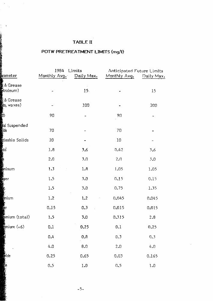
These fo rmer NPDES and sewer use permi t l imits a re summar ized in Tables I and 11, respect ively. For comparison, t h e final w a t e r quali ty based blP9ES permit l imi t s and an t ic ipa ted C i t y of Att leboro p re t r ea tmen t l imits a r e also included in Tables I and 11, respectively.
Faced with the task of upgrading exis t ing t r ea tmen t operat ions and select ing and implementing advanced t r e a t m e n t process technology t o m e e t wa te r quali ty based ef f luent and p re t r ea tmen t l imits, Texas Instruments re ta ined United Engineers & Cons t ruc to r s Inc. (UERcC) of Soston, Vassachuse t t s to provide engineering, design and s t a r tup serv ices for this project . ln May of 1985, IJE&C commenced pilot tes t ing of several advanced t r e a t m e n t process technologies in order to establ ish compliance, design, and operat ing d a t a for the systetin or sys t ems t o be se l ec t ed f o r implementat ion. The following advanced t r ea tmen t process technologies were t e s t ed on-site using e f f luents f r o m t h e existing was te t r e a t m e n t processes discharging t o Coopers Pond and to t h e City of Att leboro POTW:
o Insoluble (iron) sulfide precipi ta t ion and fi l tration.
o Membrane microf i l t ra t ion.
o Chela t ing resin ion exchange.
o Soluble (sodium) sulfide precipi ta t ion and f i l t ra t ion.
- 2-

NPOES PERMIT LIMITS (mg/l)
1977 Permit Cur ren t ?ermi t Monthly Avg. Daily Max. Monthly Avg.
15 15
20
2 .n
I. .0
0.5
0.5
0.5
0.2
0.05
30
2 .o
z .n
1 .o
1 .O
1 .o
0.2
0.1
- -
0.05 0.1
Monitor 3 n l y Monitor Only
1 .n z .n
15
20
0.17
1.75
I .n
0.15
n .4
n ,025
0 .no7
0.1
0.09
0 . O x
0.02
1.7
15
30
2 .0
1.75
1.25
0.15
0.75
0.025
o .n5
1.5
0.09
0.15
0 .OR
4.1
-3-

TABLE I (Cont.)
1977 Pe rmi t P a r a m e t e r Monthly Avg. Daily Max.
Residual Chlorine
Selenium
2.0
- 2 .a -
Cyanide 0.5 1 .o
Fluor i de 18 36
Phosphrous Monitor Only Monitor 3 n l y
Palladium 0.05 0.1
Boron Monitor q n l y Monitor Only
Tota l Toxic Oganics - -
N O A E L ( ~ ) -
Cur ren t Pe rmi t Monthly Avg. Daily Max.
0.02 0.025
0.1 0.45
0.13 0.185
9.0 9 .1
1 .D 1 .0
I .05 1.1 ,
2.0 2 .o
- 2.13
- 6096
Monitor -13nly Monitor 3 n l y
Notes:
1.
2.
No Observed Acu te Ef fec t Level (NOAEL) specif ies the dilution of the t r e a t e d was tewa te r sample in which a major population of the t e s t organism (Daphnia Pulex) survives 48 hours. In this case; 60?6 wastewater , 40 "/o d i 1 uti on w a t e r . No Observed Chronic Ef fec t Level (NOCEL) specif ies the dilution of the t r e a t e d was tewa te r sample in which the normal l ife production cycle of juveniles of t he major population of the test organism is unaffected through 7 days of tes t ing. In this case, no permi t l imit for was tewa te r sample dilution was specified - only a requirement t o monitor and report .
-4-
imeter
i Grease roleum)
3( Grease i, waxes)
1 Suspended Is
eable Solids
€
iinum
)er
nium
!r
mium ( total)
ium (+6)
TABLE I1
POTW PRETREATMENT LIMITS (mg/I)
1984 Limits Monthly Avg. Daily Max.
-
-
90
70
I. 0
1.8
2 .0
1.3
1.5
1.5
1.2
0.1 5
1.5
0.1
0.4
4.0
0.25
0.5
15
10'3
-
- -
3.6
3.0
1.8
3 .O
3 .O
1.2
0.3
3.0
0.25
0.R
8.0
0.65
1 .o
- 5-
AnticiDated Future Limits Monthly Avg.
-
-
9n
70
10
0.43
2.0
1.05
0.1 5
0.75
0.045
0.015
0.31 5
0.1
0.3
2.0
0.03
0.5
Daily Max.
15
100
-
3.6
3 .O
1.05
0.1 5
1.35
0.04 5
0.015
2.8
0.25
0.3
4 .O
0.165
1.0

The pilot tes t ing program involved six months of d a t a collection and biotoxicity testing. In the Final analysis of t h e pilot testing d a t a , the insoluble sulfide precipitation process was selected for t h e discharge to Coopers Pond, a n d the membrane microf i l t ra t ion process was se lec ted for the discharge to the C i ty o f Attleboro POTW.
In parallel with the pilot scale tes t ing prograin, an extensive faci l i ty wide source reduction study was conducted t o reduce the volume of was tewa te r and hazardous was te s produced f rom t h e various manufactur ing operations. The study recommended several manufactur ing process modifications in addition to those which had already been implemented by TI to achieve fur ther was tewa te r and hazardous waste reduct ions including:
o 21ating line r insetank w a t e r sparging (distribution).
o Conductivity controlled rinsing.
o Timer controlled rinsing.
o Coun te rcu r ren t rinsing.
o High eff ic iency spray rinsing.
o Chemical substi tution.
Process modifications current ly being implemented h y TI a re expected to reduce facility's overall was t ewa te r discharge by approxirnately 150,000 - 200,000 gallons per day (nearly a 20% reduction).
Il
Design of the advanced was tewa te r t r e a t m e n t system, which incli ided J
10,000 square foot addition t o the existing was tewa te r t r e a t m e n t building, commenced in November 1985 following successful completion of the pilot tes t ing program. Construct ion began in June 1986 and was essentially completed in October 1987, a t which t i m e t h e advanced was tewa te r t r e a t l n e n t process system s t a r t u p and shakedown procedures began.
-6-
EM DESIGN F E A T W E S
Insoluble Sulfide Precipitation
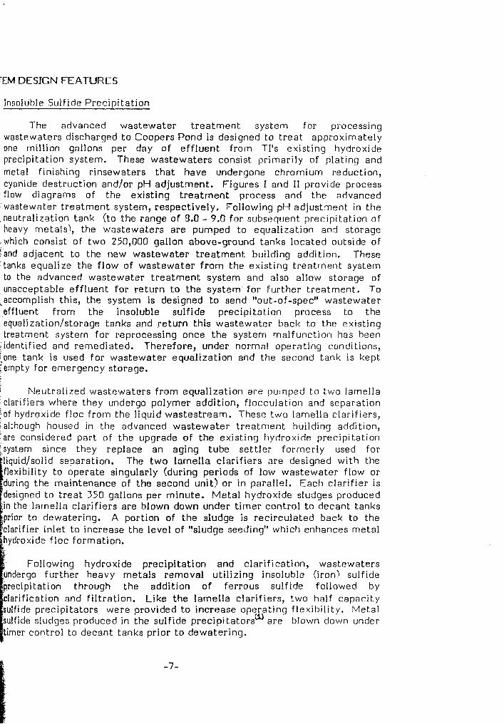
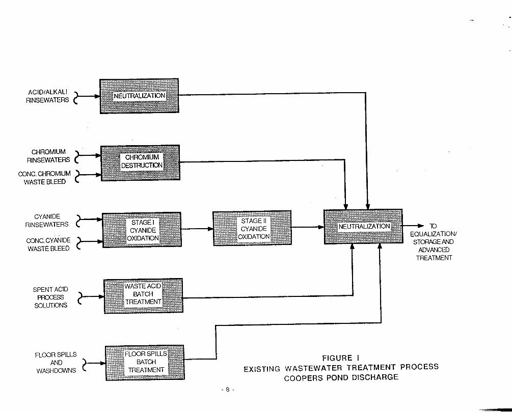
The advanced was tewater t r e a t m e n t system For processing wastewaters discharged t o Coopers Pond is designed to t r e a t approximately one million gallons per day of e f f luent from TI'S existing hydroxide precipitation system. These was tewa te r s consist primarily of plating and metal finishing r insewaters t h a t have undergone chromium reduction, cyanide destruction and/or pH adjus tment . Figures I and I1 provide process flow diagrams of the existing t r e a t m e n t process and t h e advanced wastewater t r e a t m e n t sys tem, respectively. Following p1-i ad jus tTen t in t h e neutralization tank (to t h e range of 8.0 - 9.0 for subsequent precipitation of heavy metals), the was tewaters are pumped to equalization and s torage which consist o f two 250,000 gallon above-ground tanks loca ted outside of and adjacent to the new was tewa te r t r e a t m e n t building addition. These tanks equalize the flow of was tewa te r f rom the existing t r e a t m e n t sys tem to the advanced was tewa te r t r e a t m e n t sys tem and also allow s torage of unacceptable e f f luent for r e tu rn to the sys t em fo r fur ther t r ea tmen t . To accomplish this, the system is designed to send "out-of-spec1' was t ewa te r effluent from the insoluble sulfide precipitation process to the equali z a t i o d s t o r a g e tanks and re turn this was tewa te r back to the existing treatment system for reprocessing once t h e sys tem malfunction has been identified and remediated. Therefore, under normal operating conditions, one tank is used for was tewa te r equalization and t h e second tank is kept empty f o r emergency storage.
Neutralized was tewa te r s f rom equalization are pu:nped to two lamella clarifiers where they undergo polymer addition, flocculation and separation of hydroxide f loc f rom the liquid wastestrearn. These two lamella clarifiers, although housed in the advanced was tewa te r t rea t rnent building addition, are considered par t of t h e upgrade of t h e existing hydroxide precipitation system since they replace an aging tube se t t l e r former ly used for liquid/solid separation. The two lamel la clarifiers a r e designed with the flexibility t o ope ra t e singularly (during periods of low was tewa te r flow or uring the main tenance of t h e second unit) or in parallel. Each clarifier is esigned to t r e a t 350 gallons per minute. Meta l hydroxide sludges produced n the lamella c la r i f ie rs are blown down under t imer cont ro l to decant tanks rior to dewatering. A portion of t h e sludge is rec i rcu la ted back to the larifier inlet t o increase the level of "sludge seeding" which enhances me ta l ydroxide f loc formation.
Following hydro xi de precipitation and cl ari f i c a ti on, was tewaters ergo fur ther heavy me ta l s removal utilizing insoluble (iron) sulfide cipitation through the addition of ferrous sulfide followed by rification and fi l tration. Like t h e lamella clarifiers, two half capac i ty fide precipitators were provided to increase operating flexibility. Metal fide sludges produced in t h e sulfide precipitatorsw a r e blown down under er control to decant tanks prior t o dewater ing .
-7-
ACIDJALKALI RINSEWATERS
CHROMIUM RINSEWATERS
CONC. CHROMIUM WASTE BLEED
CYANIDE RINSEWATERS
m c . CYANIDE WASTE BLEED
-la LlZATlONl
STORAGE AND ADVANCED
TREATMENT
SPENT ACID PROCESS
SOLLFTloNS
FLOOR SPILLS AND FIGURE I WASHDOWNS EXISTING WASTEWATER TREATMENT PROCESS
COOPERS POND DISCHARGE - 8 -

HYDROXIDE SLUDGE 70
DEWATERING
SULFIDE SLUDGE To
DEWATERING
I I I
DIA FILTRATION
FIGURE i I ADVANCED WASTEWATER TREATMENT SYSTEM
COOPERS POND DISCHARGE - 9 -
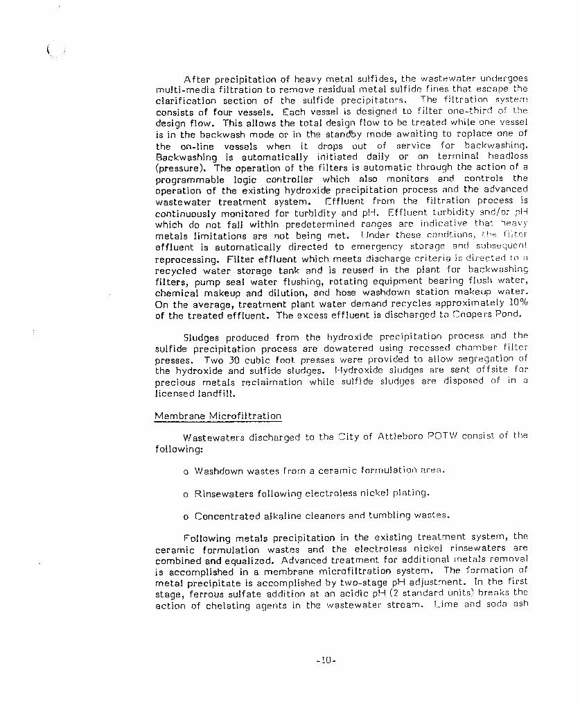
.4fter precipitation of heavy meta l sulfides, the was tewa te r undergoes multi-media f i l t ra t ion t o remove residual me ta l sulfide fines tha t e scape the c la r i f ica t ion sect ion of the sulfide precipi ta tors . The f i l t ra t ion system consis ts of four vessels. Each vessel is designed to f i l ter one-third o f the design flow. This allows t h e to t a l design flow t o be t r ea t ed while one vessel is in t h e backwash mode or in the standby mode await ing to rep lace one of the on-line vessels when i t drops out of service for backwashing. Backwashing is au tomat ica l ly init iated daily or on te rmina l headloss (pressure). The operat ion of the filters is au tomat i c through the ac t ion of a programmable logic control ler which also monitors and controls the opera t ion of t he existing hydroxide precipi ta t ion process and t he advanced was tewa te r t r e a t m e n t system. Eff luent from the f i l t ra t ion process is continuously monitored for turbidity and pH. Eff luent turbidi ty and/or pH which do not fall within predetermined ranges a re indicative tha t heav)! m e t a l s l imi ta t ions a re not being me t . I Jnder these condtions, rhp tiltel
e f f luen t is automatical ly directed to emergency s torage and SlJbSeclU?r7t
reprocessing, F i l te r e f f luen t which mee t s discharge c r i te r la is d i rec ted to d recyc led w a t e r s torage tank and is reused in the plant f o r backwashing f i l t e rs , pump seal wa te r flushing, ro ta t ing equipment bearing f l u s h water , chemica l makeup and dilution, and hose washdown s ta t ion makeup water . On the average , t r e a t m e n t plant water demand recyc les approxirnately 10% of t h e t r e a t e d e f f luent . The excess eff luent is discharged t o Coopers Pond.
Sludges produced f r o m the hydroxide precipi ta t ion process and the sulfide precipi ta t ion process a r e dewatered using recessed chamber f i l ter presses. Two 30 cubic foot presses were provided to allow segregat ion of the hydroxide and sulfide sludges. Hydroxide sludges a re sen t of fs i te f o r precious me ta l s reclaimation while sulfide sludges a r e disposed of in a l icensed landfill.
Membrane Microfi l t ra t ion
Wastewaters discharged to the C i ty of Attleboro POTW consist of the f ol lowing:
o Washdown was te s f rom a ce ramic formulatioi3 a rea .
o Rinsewaters following electroless n icke l plating.
o Concen t r a t ed alkaline c leaners and tumbling wastes .
Following me ta l s precipi ta t ion in the existing t r e a t m e n t sys tem, the c e r a m i c formulat ion was tes and the e lec t ro less n i c k e l r insewaters a re combined and equalized. Advanced t r ea tmen t for additional meta ls removal is accomplished in a membrane microf i l t ra t ion system. The formation of m e t a l p rec ip i ta te is accomplished by two-stage pH a d j u s t v e n t . In the first s t age , fe r rous su l fa te addition a t an acidic pf-i ( 2 s tandard units) breaks the ac t ion of chelat ing agents in the was tewater s t r eam. Lime and soda ash
-10-

(sodium ca rbona te ) a r e added in the second s t a y t o frirm irisoliJble metal hydroxide and lead carbonate prec ip i ta tes . The solids formed in the precipitation process a re separa ted f rom the iiquid st.ream in the membrane microf i l t ra t ion modules. Ff f luent from the second stage p ! i r eac to r i:: r ec i rcu la ted through the membrane modules. "hysica! fi l tration of ths prec ip i ta ted solids occurs a t the memhrane slurface which has a nominal pore ra t ing of 0.2 microns. Prec ip i ta ted solids a r e retained and wa te r (permeate) passes the membrane and is discharged. . I s the concent ra t ion of solids builds in the rec i rcu la ted was te s t r eam, a controlled volume is bled o f f a s was te sludge under t imer control and is then dewatered h y f i l t e r press for of fs i te disposal.
A second rnembrane microf i l t ra t ion is employed to t r e a t spent ~ I k a l i n t . was te for me ta l s removal using a twcl-stage hydroxide precipitation aroci::;.? followed by microfil tration of t he hydron.irle prec ip i ta te . l lff luents (pe rmea te ) f rom both systems a r e combined for pl-1 adjustment and a r e discharged to t h e City of Attleboro sewer. provides a process flow diagram of the advanced was tewa te r t rea t rnent system for the POTLV discharge.
Figure 111
Proara tnmable Process Control Loaic Svstern
The monitoring and control of t h e en t i re was tewa te r t rea t rnent sys tem is accomplished through a programmable logic controller (PLC) systern. T h e PLC consists of t h e following basic components:
o Compute r or cent ra l processing unit (CPLJ),
o R e m o t e input/output modules.
o Cont ro l logic software.
The input/output (I/O) modules a re basically fieid located circuit '>t>di-dS t 1 I
a r e directly wired to and communica te w i t h f i e l d lncated prncesl, P ~ U I ~ ~ T - I P
devices (motor s t a r t e r s for pumps and mixers, switches, 111 l / r l I ? \ ) t r ansmi t t e r s , level t ransmi t te rs , etc.). network, the C'P( 1
communica te s wi th the 1/0 modules. \ / i a the network, t he SPIJ rece ives analog and digital signals which represent d a t a such a s on/off s ta tus , liquid level, pH, ORP and t empera tu re readings from the I/O modules. The CPU updates its logic control sof tware with the new da ta , performs a l l calculations and logic checks, gene ra t e s new output, and then sends the new output (analog and digital signals) on the network buss to the appropr ia te input/output module. The I/O module, in turn, utilizes the rece ived d a t a t o manipulate associated process pquipment devices.
I Jstnq a radial
?he process control system a t TI utilizes a -Texas Instruments 561) PLC. The TI sys tem monitors and/or controls approximately 1509 da ta points. The sys tem comple tes the receiving of ail input d a t a and updating o f all output d a t a f o r t h e 1500 points every 4 5 milliseconds.
-11-

FROM PTC AND
ELECTFOLESS NICKEL
TREATMENT SYSTEMS
SLUDGE TO DEWATERING
b- PERMEATE
CONCEmlED ALKALINE
WASTE
SLUDGE TO DEWATERING
FIGURE 111 ADVANCED WASTEWATER TREATMENT SYSTEM - POTW DISCHARGE
- 1 2 -
I SYSTEM STARTUP
Compliance Schedule
i k i
1 E
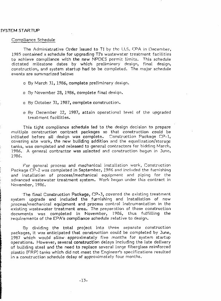
The Administrative Order issued t o TI by the [J.S. FPA in December , 1985 contained a schedule for upgrading TI'S was tewa te r t r e a t m e n t faci l i t ies t o achieve Compliance with t h e new NPDES permit l imits. This schedule d ic ta ted milestone da tes by which preliminary design, final design, construction, and system s ta r tup had t o be completed. The major schedule even t s a r e summarized below: t
i
l o By March 31, 19R6, comple t e preliminary design.
o By November 28, 1996, comple t e final design.
o By October 31, 1987, comple t e construction.
o By December 12, 1987, a t t a i n operational level of the upgraded E t r e a t m e n t facil i t ies.
This t ight compliance schedule led t o t h e design decision to prepare multiple construction c o n t r a c t packages so t h a t construction could be ini t ia ted before all design was complete . r o n s t r u c t i o n Package CP-1, covering site work, the new building addition and the equalization/storage tanks, was completed and released t o general con t r ac to r s for bidding March, 1986. A general con t r ac to r was se lec ted and construction begun in June , 1986.
k
For general process and mechanical installation work, Construction Package CP-2 was completed in September , 1986 and included t h e furnishing and installation of processlmechanical equipment and piping for the advanced wastewater t r e a t m e n t system. Work began under t h i s con t r ac t in November, 1986.
The final Construction Package, CP-3, covered the existing t r e a t m e n t system upgrade and included t h e furnishing and installation of new process/mechanicaI equipment and process control instrumentation in the existing was tewa te r t r e a t m e n t area. The preparat ion of these construction documents was completed in November, 1986, thus fulfilling the requirements of t h e EPA's compliance schedule re la t ive to design.
By dividing t h e t o t a l project into three sepa ra t e construction packages, it was ant ic ipated t h a t construction could be completed by June , 1987 which would allow approximately f i v e months for system s ta r tup operations. Howeve:, several construction delays including t h e l a t e delivery of building s tee l and t h e need t o replace several large fiberglass reinforced plastic (FRP) tanks which did not m e e t t h e Engineer's specifications resulted in a construction schedule delay of approximately four months.
-13-

Star tup Planninq
The construct ion delay forced a major revision to the original s ta r t k i p plans. S ta r tup operat ions had to begin before construction w a s con lp ie t r and all individual pieces of equipment could be thoroughly checked antf tes ted. Additionally, it was necessary to set final construction priori t i es based on t h e need to have cer ta in subsystems and support equipment operat ional , as s t a r tup systematical ly progressed.
With the f inal goal of meet ing a plant operat ional da t e of Deember 1 2 , 1987, a comprehensive s t a r t u p schedule was developed in ear ly October . This schedule de ta i led individual tasks and expec ted durations and noted cr i t ical ac t iv i t ies which a f f ec t ed the overall s t a r tup completion da te . All tasks were ca tegor ized according to responsible engineering disciplines: e lec t r ica l , ins t rumenta t ion , mechanical , and chemical process. I s t a r tup t e a m comprised of personnel froin both TI and IJE&C was formed. Team members were engineers and technicians who were involved in the project from the ea r ly design phase.
Although t h e s t a r t u p schedule did not provide any "float", i t did show tha t the t r e a t m e n t plant could become operat ional on t ime if major setbacks, such as equipment failures, did not occur and i f comple te coordination and cooperat ion among cont rac tors , equipment suppliers, T! and UE&C f ie ld personnel could be a t ta ined .
S ta r tup Opera t ions
S ta r tup operat ions began on October 19th a f t e r most o f the plant 's piping had been hydrotested. Since the Administrative 9 r d e r covered only TI'S sur face w a t e r discharge, and due to a delay in InstalIing the membrane microf i l t ra t ion sys tem f o r t r s a t m e n t of was tewater directed to the san i ta ry sewer, all e f fo r t s were placed on operat ing the advanced was tewa te r t r e a t m e n t system f o r discharges t o Coopers Pond.
The f i r s t tasks comple ted were the programming of the Pl-C: and establishing communicat ion between the PLC and each of the r e m o t e I/O modules. A t t he s a m e t ime, t he main control panel was ac t iva ted and panel mounted ins t ruments were t e s t ed and cal ibrated. Since the schedule t i m e f r a m e did not allow for checking of all control loops prior to mechanical equipment s t a r tup , this task was accomplished as the individual mechanical subsystems were placed into operation.
The init ial mechanical s t a r tup e f fo r t s were placed on t he equal izat ion/s torage tanks and the associated pumping sys tem, T hroughoii t the s t a r t u p operat ions, t he two 250,000 gallon equalization tanks provided R
reservoir of non-potable process wa te r for equipment hydrotest ing and subsystem s ta r tup . When the pumping system was operat ional , s t a r tup progressed sys temat ica l ly along the main flowpath of the t r ea tmen t sys tem. The c la r i f ie rs were first placed into operat ion, followed by the precipi ta tors
-14-

d the multi-media fi l ters. In parallel with these ef fo r ts , peripheral ubsystems such a s the c la r i f ie r polymer feed sys tem, the lime feed sys tem, e fe r rous s u l f a t e and fe r rous sulfide s y s t e v s 2nd t k <i!:?r presses d e w en t s :a r t up.
Although small problems arose, typical of any major s ta r tup , process up operations generally progressed on schedule. By November ZOth,
oximately one month after s t a r tup opera t ions began, non-potable ess water was flowing through t h e advanced was tewater t r e a t m e n t m and all chemical feed sys t ems were operational. A major schedule
complishment was made on November 24th when was tewater was cessed through the system.
From tha t da te , f ine tuning of control loops and chemical feed justments continued until December 10, 1957 when the system became l y operational, two days before t h e required da te .
When was tewa te r was initially d i rec ted through the advanced tewater t r e a t m e n t sys tem, less than th ree weeks remained for adjusting process chemis t ry t o produce an e f f luent meet ing the stringent NPDES
rmit requirements. The f i r s t t ask during process s t a r tup was to build a od f loc in the flocculators ups t ream of the clarifiers. T h i s was complished by injecting a slightly higher than normal dosage of polymer d by recirculating s e t t l e d sludge from t h e c la r i f ie r back to the
culator. Once an accep tab le f loc was maintained, polymer dosing was back t o minimum opera t ing level.
Another process requi rement was building an adequate sludge blanket the precipitators. This proved more difficult since the total solids
ncentration leaving t h e c la r i f ie rs and en te r ing into the prec ip i ta tors was r y low. To reduce the t ime necessary t o build the sludge blanket, excess
ous sulfide ( the predominant chernical makeup of the sludge blanket) was ted to the precipitators; however, th i s was only partially successful. A a1 sludge blanket level was reached only a f t e r continuous processing of
stewater for a period of approximate ly t h r e e weeks.
Despite initial delays and problerns, t h e first g rab sample taken cember 1st from filter e f f luent , after only t h r e e days of processing stewater, showed exce l len t results. With t h e exception of phosphorus, all
contituents analyzed for m e t t he daily ave rage l imits imposed by the
From this point, a comprehensive sampling program was implemented. ical results f rom 8-hour composite samples taken during the f i r s t 1 weeks of operation a r e summar ized in Table 111. Fur ther adjustment
e process chemis t ry continues.
-15-

TABLE III FINAL EFFLUENT MOFarORMG RESULTS
PARAMETER COMXNTRATION (mdl)
Cr-T sn NPDES Permit Monthly Avg. Limit 0.4 2 .o 1 .D 0.025 1.75 0.02 0.007 1.05 0.15 0.031 0.17 1 .o 0.19
NPDES Permit Daily Max. Limit 0.75 2.0 I .o 0.025 1.75 O.OA 0.05 1.1 0.15 0.15 2 -0 1.25 1.59
- At - Ni - Pb - cu - Pd !!!l - - Fe - Cd - P - 8 - Zn
Date of Sampling
12/1/87
12/9/87
12/10/87
12/12/87
12/13/87
12/14/87
12/15/87
12/16/87
NOTE:
0.004 0.580 1.345 o.001 0.05~
< 0.030 0.763 0.122 0.038 0.020
< 0.030 0.888 0.955 < 0.020 0.152
< 0.030 0.751 1.300 < 0.020 0.11~
(0.030 0.640 1.310 (0.020 0.134
0.041 0.504 0.82R < 0.020 0.229
< 0.030 0.707 0.750 < 0.020 0.19)
< 0.030 0.721 1.350 < 0.020 0.066
Effluent samples were &hour composites. Samples were taken, preserved and analyzed in accordance with 40 CFR 136.
0.055
< 0.030
(0.030
(0.030
< 0.030
0.073
< o m 0
-16-
< 0 .008 0.048
0.044
0.034
0.104
0.025
< 0.008
< 0.010
< 0.010
< 0.010
(0.010
<0.010
< 0.010
to.010
< 0.010
o m 1
0.029
0.072
0.157
0.166
0.139
0.1 39
0.0 19
< 0.030 < 0.030
< 0.030 < 0.030
< 0.030
< 0.030
< 0.030
0.049
0.065
0.129
0.398
0.419
0.287
0.297
0.183
0.704
0.229
0.301
0.266
0.186
0.2Cr3
0.246
0.228
0.005
< 0.010
< 0.010
0.022
0.011
< 0.010 < 0.0ro
< o . m

--'
6
Fii fluent ilizing nple,
nally, was the
a t 1[
on December 16th, a 24-hour composite sample of the system sent to a laboratory for t h e first biological toxicity test daphnid, D a hnia Pulex, as t h e a c u t e test organism. The
10% s t rength le, J.e. undiluted), passed.
-17-

SUMMARY
The Environmental Protect ion Agency i s current ly using site-specif ic water qual i ty c r i te r ia to develop wastewater e f f luent l i m i t s for direct discharges. Texas Instruments, in Att leboro, Vassachusetts was one o f the f i r s t industries i n New England t o receive an NPDES permi t based on the new water qual i ty cr i ter ia. Al though the discharge l i m i t s dictated by the i r new permi t are among the most str ingent in the country, Texas Instruments commit ted the technical and economic resources required t o support t h i s ambitious environmental compliance project. Appl icat ion of advanced technology was only part o f TI'S success s t o r y . Implementat ion o f faci l i ty-wide source reduct ion programs, f lex ib i l i t y in the t reatment system design, and to ta l commitment and cooperation among t he design/startup team members and f a c i l i t y management and technical personnel all played a major par t in this state-of-the-art demonstration project.
-18-
ACKNOWLEDGMENTS
V., I<elleher, C.M., and Yeligar, M.G., "Metal Finishing Wastewater Upgrade with an Insoluble Sulfide Precipi ta t ion Process", presented a t AESF/EPA Conference on Pollution Control for t h e Metal Finishing
February 10, 1987.
min Y ., "Advanced Wastewater T r e a t m e n t Study and Pilot Testing the IW-003 Discharge a t Texas Instruments-Attleboro", d Engineers K Constructors Inc., August 15, 1986.
neem & Constructors Inc., Vre l imina ry Design Manual for t h e Instruments Industrial Wastewater T rea tmen t Eff luent Upgrade",
ncis J. Jr., and Elliott , Michael J., "Meeting t h e Water Quality ria for t h e Metal Finishing Industries", May 2, 1986.
-19-


