11030/2 Te
1
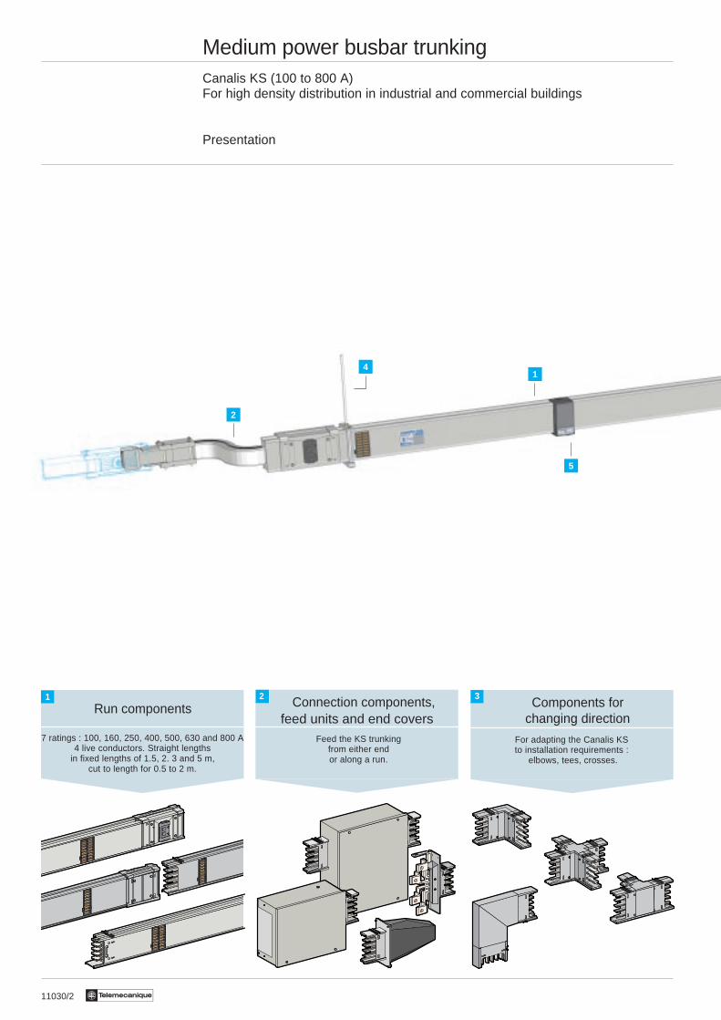
Medium power busbar trunkingCanalis KS (100 to 800 A)For high density distribution in industrial and commercial buildings
Presentation
Run components
7 ratings : 100, 160, 250, 400, 500, 630 and 800 A4 live conductors. Straight lengths
in fixed lengths of 1.5, 2. 3 and 5 m,cut to length for 0.5 to 2 m.
Connection components, Components forchanging direction
For adapting the Canalis KSto installation requirements :
elbows, tees, crosses.
2 3
Feed the KS trunkingfrom either endor along a run.
feed units and end covers
41
2
5
11030/3Te
1
0
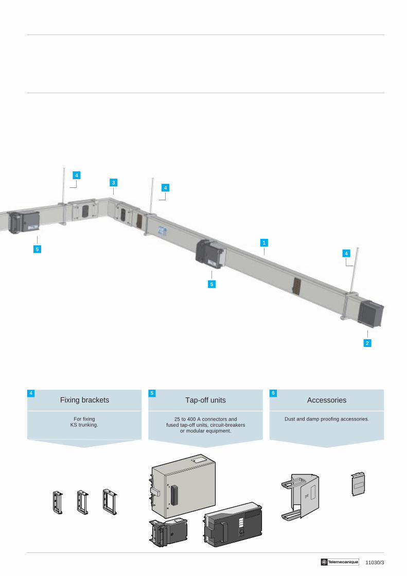
Fixing brackets
For fixingKS trunking.
Tap-off units
Dust and damp proofing accessories.
Accessories4 5 6
25 to 400 A connectors andfused tap-off units, circuit-breakers
or modular equipment.
4
4
4
1
3
5
5
2
11031/2 Te
Medium power busbar trunkingCanalis KS (100 to 800 A)
Description
General
Canalis KS is designed for medium power distribution with high tap-off density in industrial and commercial buildings(exhibition halls, hypermarkets, office blocks, etc.).The range is available in 7 ratings from 100 to 800 A.The standard IP 52 degree of protection makes KS suitable for the majority of locations. It can be increased to IP 54 bythe addition of dust and damp proof blanking plates on the tap-off outlets.Tapping off is via tap-off units. These units, from 25 to 400 A, can be safely removed while live.100 to 250 A trunking can take connectors and tap-off units up to 250 A.Higher rated trunking can take any tap-off unit from the range.
Run components
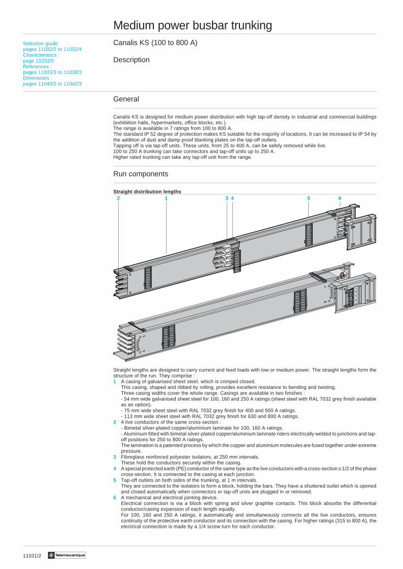
Straight distribution lengths
Straight lengths are designed to carry current and feed loads with low or medium power. The straight lengths form thestructure of the run. They comprise :1 A casing of galvanised sheet steel, which is crimped closed.
This casing, shaped and ribbed by rolling, provides excellent resistance to bending and twisting.Three casing widths cover the whole range. Casings are available in two finishes :- 54 mm wide galvanised sheet steel for 100, 160 and 250 A ratings (sheet steel with RAL 7032 grey finish availableas an option).- 75 mm wide sheet steel with RAL 7032 grey finish for 400 and 500 A ratings.- 113 mm wide sheet steel with RAL 7032 grey finish for 630 and 800 A ratings.
2 4 live conductors of the same cross-section :- Bimetal silver-plated copper/aluminium laminate for 100, 160 A ratings.- Aluminium fitted with bimetal silver-plated copper/aluminium laminate riders electrically welded to junctions and tap-off positions for 250 to 800 A ratings.The lamination is a patented process by which the copper and aluminium molecules are fused together under extremepressure.
3 Fibreglass reinforced polyester isolators, at 250 mm intervals.These hold the conductors securely within the casing.
4 A special protected earth (PE) conductor of the same type as the live conductors with a cross-section ≥ 1/2 of the phasecross-section. It is connected to the casing at each junction.
5 Tap-off outlets on both sides of the trunking, at 1 m intervals.They are connected to the isolators to form a block, holding the bars. They have a shuttered outlet which is openedand closed automatically when connectors or tap-off units are plugged in or removed.
6 A mechanical and electrical jointing device.Electrical connection is via a block with spring and silver graphite contacts. This block absorbs the differentialconductor/casing expansion of each length equally.For 100, 160 and 250 A ratings, it automatically and simultaneously connects all the live conductors, ensurescontinuity of the protective earth conductor and its connection with the casing. For higher ratings (315 to 800 A), theelectrical connection is made by a 1/4 screw turn for each conductor.
Selection guide:pages 11032/2 to 11032/4Characteristics :page 11032/5References :pages 11033/3 to 11038/3Dimensions :pages 11040/2 to 11042/3
1 4 5 62 3
11031/3Te
Medium power busbar trunkingCanalis KS (100 to 800 A)
Description
Special components
i Fire barrier lengthTo cross a fire partition, between two areas of a building. Fire resistance : 2 h (A120) conforming to ISO 834.
i “Made to measure” lengthTo alter the length of a run (for example, between two components for changing direction). These components aremanufactured, on request, from 500 mm to 1995 mm, in multiples of 5 mm. They do not have tap-off outlets.
Connection components and feed units
Feed units
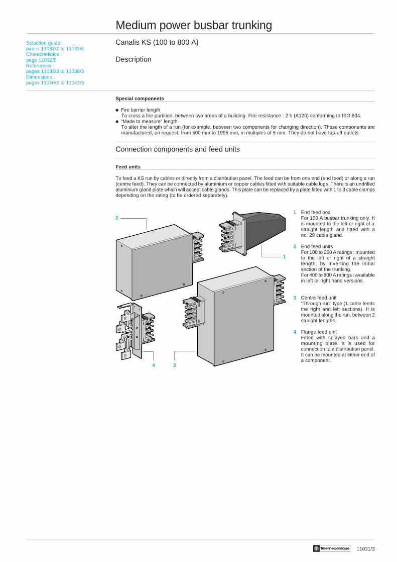
To feed a KS run by cables or directly from a distribution panel. The feed can be from one end (end feed) or along a run(centre feed). They can be connected by aluminium or copper cables fitted with suitable cable lugs. There is an undrilledaluminium gland plate which will accept cable glands. This plate can be replaced by a plate fitted with 1 to 3 cable clampsdepending on the rating (to be ordered separately).
1 End feed boxFor 100 A busbar trunking only. Itis mounted to the left or right of astraight length and fitted with ano. 29 cable gland.
2 End feed unitsFor 100 to 250 A ratings : mountedto the left or right of a straightlength, by inverting the initialsection of the trunking.For 400 to 800 A ratings : availablein left or right hand versions.
3 Centre feed unit“Through run” type (1 cable feedsthe right and left sections). It ismounted along the run, between 2straight lengths.
4 Flange feed unitFitted with splayed bars and amounting plate. It is used forconnection to a distribution panel.It can be mounted at either end ofa component.
Selection guide:pages 11032/2 to 11032/4Characteristics :page 11032/5References :pages 11033/3 to 11038/3Dimensions :pages 11040/2 to 11042/3
2
3
1
4
11031/4 Te
Medium power busbar trunkingCanalis KS (100 to 800 A)
Description
Connection components and feed units (continued)
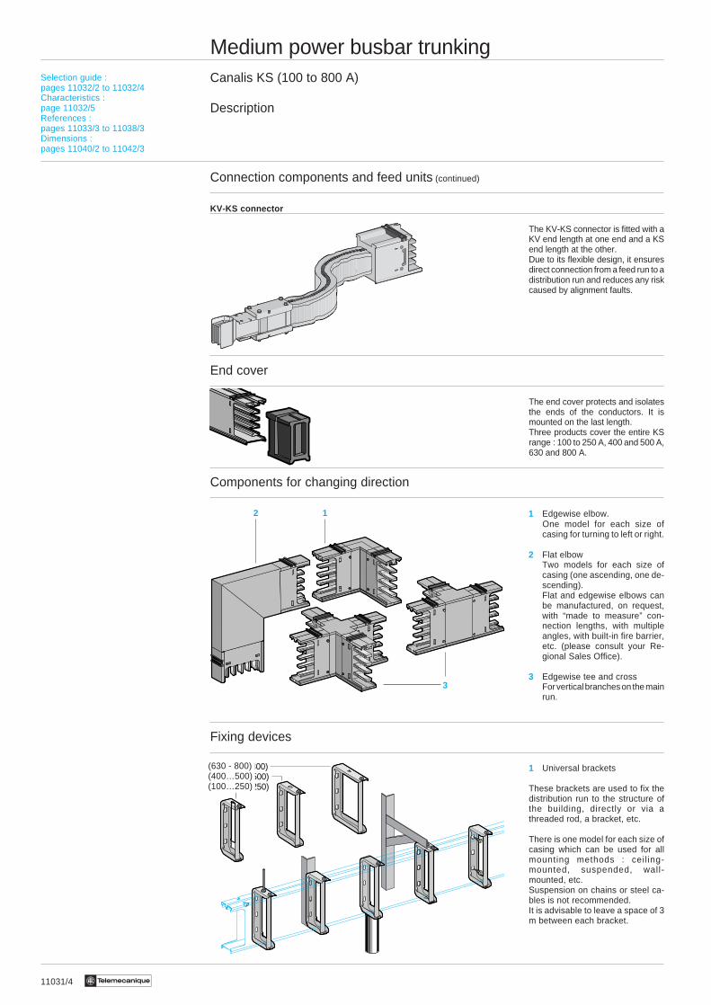
KV-KS connector
The KV-KS connector is fitted with aKV end length at one end and a KSend length at the other.Due to its flexible design, it ensuresdirect connection from a feed run to adistribution run and reduces any riskcaused by alignment faults.
End cover
The end cover protects and isolatesthe ends of the conductors. It ismounted on the last length.Three products cover the entire KSrange : 100 to 250 A, 400 and 500 A,630 and 800 A.
Components for changing direction
1 Edgewise elbow.One model for each size ofcasing for turning to left or right.
2 Flat elbowTwo models for each size ofcasing (one ascending, one de-scending).Flat and edgewise elbows canbe manufactured, on request,with “made to measure” con-nection lengths, with multipleangles, with built-in fire barrier,etc. (please consult your Re-gional Sales Office).
3 Edgewise tee and crossFor vertical branches on the mainrun.
Fixing devices
1 Universal brackets
These brackets are used to fix thedistribution run to the structure ofthe building, directly or via athreaded rod, a bracket, etc.
There is one model for each size ofcasing which can be used for allmounting methods : ceil ing-mounted, suspended, wall-mounted, etc.Suspension on chains or steel ca-bles is not recommended.It is advisable to leave a space of 3m between each bracket.
1 (630 - 800) (315…500) (100…250)
(630 - 800)(400…500)(100…250)
Selection guide :pages 11032/2 to 11032/4Characteristics :page 11032/5References :pages 11033/3 to 11038/3Dimensions :pages 11040/2 to 11042/3
12
3
11031/5Te
Medium power busbar trunkingCanalis KS (100 to 800 A)
Description
Tap-off units
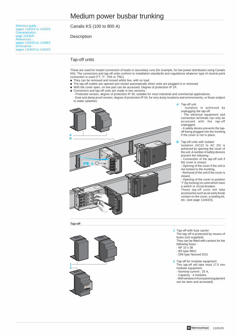
These are used for instant connection of loads or secondary runs (for example, for low power distribution using CanalisKN). The connectors and tap-off units conform to installation standards and regulations whatever type of neutral pointconnection is used (TT, IT, TNS or TNC).i They can be removed and moved whilst live, with no load.i The tap-off outlets are opened and closed automatically when units are plugged in or removed.i With the cover open, no live part can be accessed. Degree of protection IP 2X.i Connectors and tap-off units are made in two versions :
- Protected version, degree of protection IP 40, suitable for most industrial and commercial applications,- Dust and damp proof version, degree of protection IP 54, for very dusty locations and environments, or those subjectto water splashes.
A Tap-off unit- Isolation is achieved byunplugging the tap-off.- The electrical equipment andconnection terminals can only beaccessed with the tap-offunplugged.- A safety device prevents the tap-off being plugged into the trunkingif the cover is not in place.
B Tap-off units with isolatorIsolation (AC22 to AC 20) isachieved by opening the cover ofthe unit. A number of safety devicesprevent the following :- Connection of the tap-off unit ifthe cover is closed,- Opening of the cover if the unit isnot locked to the trunking,- Removal of the unit if the cover isclosed,- Opening of the cover to position“I” (by locking) on units which havea switch or circuit-breaker.These tap-off units will takeaccessories such as an early breakcontact on the cover, a sealing kit,etc. (see page 11043/3).
Tap-off
1 Tap-off with fuse carrierThe tap-off is protected by means offuses (not supplied).They can be fitted with carriers for thefollowing fuses :- NF 10 x 38- BS type 88A1- DIN type Neozed DO1
2 Tap-off for modular equipmentThis tap-off will take most 17.5 mmmodular equipment.- Nominal current : 25 A,- Capacity : 4 modules,- With window in front panel (equipmentcan be seen and accessed).
Selection guide :pages 11032/2 to 11032/4Characteristics :page 11032/5References :pages 11033/3 to 11038/3Dimensions :pages 11040/2 to 11042/3
PE =
AB
12
11031/6 Te
321
Medium power busbar trunkingCanalis KS (100 to 800 A)
Description
Tap-off units (continued)
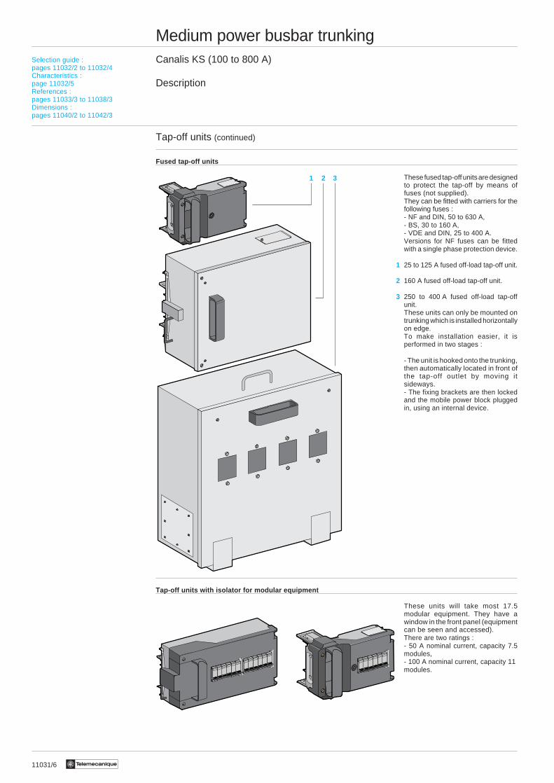
Fused tap-off units
These fused tap-off units are designedto protect the tap-off by means offuses (not supplied).They can be fitted with carriers for thefollowing fuses :- NF and DIN, 50 to 630 A,- BS, 30 to 160 A,- VDE and DIN, 25 to 400 A.Versions for NF fuses can be fittedwith a single phase protection device.
1 25 to 125 A fused off-load tap-off unit.
2 160 A fused off-load tap-off unit.
3 250 to 400 A fused off-load tap-offunit.These units can only be mounted ontrunking which is installed horizontallyon edge.To make installation easier, it isperformed in two stages :
- The unit is hooked onto the trunking,then automatically located in front ofthe tap-off outlet by moving itsideways.- The fixing brackets are then lockedand the mobile power block pluggedin, using an internal device.
Tap-off units with isolator for modular equipment
These units will take most 17.5modular equipment. They have awindow in the front panel (equipmentcan be seen and accessed).There are two ratings :- 50 A nominal current, capacity 7.5modules,- 100 A nominal current, capacity 11modules.
Selection guide :pages 11032/2 to 11032/4Characteristics :page 11032/5References :pages 11033/3 to 11038/3Dimensions :pages 11040/2 to 11042/3
11031/7Te
Medium power busbar trunkingCanalis KS (100 to 800 A)
Description
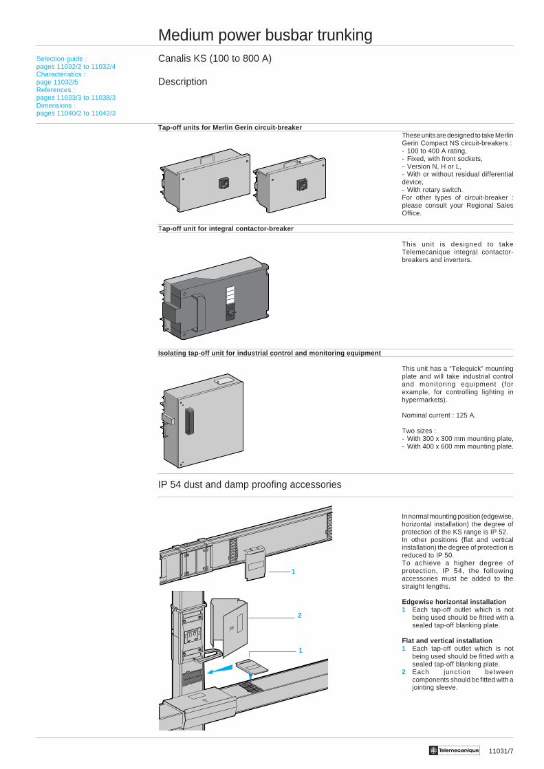
Tap-off units for Merlin Gerin circuit-breakerThese units are designed to take MerlinGerin Compact NS circuit-breakers :- 100 to 400 A rating,- Fixed, with front sockets,- Version N, H or L,- With or without residual differentialdevice,- With rotary switch.For other types of circuit-breaker :please consult your Regional SalesOffice.
Tap-off unit for integral contactor-breaker
This unit is designed to takeTelemecanique integral contactor-breakers and inverters.
Isolating tap-off unit for industrial control and monitoring equipment
This unit has a “Telequick” mountingplate and will take industrial controland monitoring equipment (forexample, for controlling lighting inhypermarkets).
Nominal current : 125 A.
Two sizes :- With 300 x 300 mm mounting plate,- With 400 x 600 mm mounting plate.
IP 54 dust and damp proofing accessories
In normal mounting position (edgewise,horizontal installation) the degree ofprotection of the KS range is IP 52.In other positions (flat and verticalinstallation) the degree of protection isreduced to IP 50.To achieve a higher degree ofprotection, IP 54, the followingaccessories must be added to thestraight lengths.
Edgewise horizontal installation1 Each tap-off outlet which is not
being used should be fitted with asealed tap-off blanking plate.
Flat and vertical installation1 Each tap-off outlet which is not
being used should be fitted with asealed tap-off blanking plate.
2 Each junction betweencomponents should be fitted with ajointing sleeve.
Selection guide :pages 11032/2 to 11032/4Characteristics :page 11032/5References :pages 11033/3 to 11038/3Dimensions :pages 11040/2 to 11042/3
1
0
2
1
1
11032/2 Te
Medium power busbar trunkingCanalis KS (100 to 800 A)
Selection guide
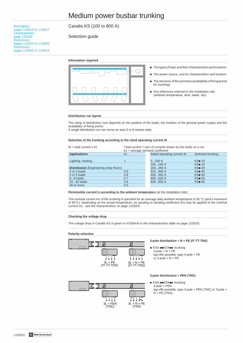
Information required
i The types of load, and their characteristics and locations.
i The power source, and its characteristics and location.
i The structure of the premises (availability of fixing pointsfor trunking).
i Any influences external to the installation site.(ambient temperature, dust, water, etc).
Distribution run layout
The siting of distribution runs depends on the position of the loads, the location of the general power supply and theavailability of fixing points.A single distribution run can serve an area 5 to 8 metres wide.
Selection of the trunking according to the rated operating current Ib
Ib = total current x k1 Total current = sum of currents drawn by the loads on a runk1 = average demand coefficient
Applications k1 Rated operating current Ib Selected trunking
Lighting, heating 1 0...100 A KSi-10100...160 A KSi-16
Distribution (Engineering shop floors) 160...250 A KSi-252 or 3 loads 0.9 315...400 A KSi-404 or 5 loads 0.8 400...500 A KSi-506...9 loads 0.7 500...630 A KSi-6310...40 loads 0.6 630...800 A KSi-8040 or more 0.5
Permissible current Iz according to the ambient temperature (at the installation site)
The nominal current Inc of the trunking is specified for an average daily ambient temperature of 35 °C (and a maximumof 40°C). Depending on the actual temperature, an uprating or derating coefficient (f1) may be applied to the nominalcurrent Inc : see the characteristics on page 11032/5.
Checking the voltage drop
The voltage drop in Canalis KS is given in V/100m/A in the characteristics table on page 11032/5.
Polarity selection
3-pole distribution + N + PE (IT-TT-TNS)
i KSA-iiED4ii trunking3-pole + N + PEtap-offs possible, type 3-pole + PEor 3-pole + N + PE
3-pole distribution + PEN (TNC)
i KSA-iiED4ii trunking3-pole + PENtap-offs possible, type 3-pole + PEN (TNC) or 3-pole +N + PE (TNS)..
Description :pages 11031/2 to 11031/7Characteristics :page 11032/5References :pages 11033/3 to 11038/3Dimensions :pages 11040/2 to 11042/3
3L + PE(IT-TT-TNS)
3L + N + PE(IT-TT-TNS)
3L + N + PE(TNS)
3L + PEN(TNC)
11032/3Te
Description :pages 11031/2 to 11031/7Characteristics :page 11032/5References :pages 11033/3 to 11038/3Dimensions :pages 11040/2 to 11042/3
Medium power busbar trunkingCanalis KS (100 to 800 A)
Selection guide
Protecting the trunking against overloads
To enable it to be extended, prefabricated busbar trunking is generally protected to its nominal current Inc (or to itspermissible current Iz if the f1 coefficient is applied according to the ambient temperature).
Protection using fuses
i Calculate the standard nominal current In of the fuse so that : In ≤ Inc1
i Select the standard rating In which is equal to or immediately below.Check that In ≥ Ib. If this is not the case, select the next highest rating of trunking.
Note : Protecting trunking using fuses is the same as limiting the rated operating current.
Protection using a circuit-breaker
i Select the circuit-breaker setting current Ir so that : Ib ≤ Ir ≤ Inc
Note : Protecting trunking using a circuit-breaker makes it possible to use the trunking at full capacity.
Electrodynamic protection against short-circuit currents
The electrodynamic withstand of the trunking should be taken into account when selecting a protective device(permissible rated peak current).i Determine (1) the 3-phase short-circuit current, prospective lcc 3 (KA) at the start of the Canalis KS.
i Check, on the current limitation curve of the selected protective device, that this limits the peak current (kÂ) to a valuebelow the permissible rated peak current of the KS trunking.Limited current ≤ Canalis current
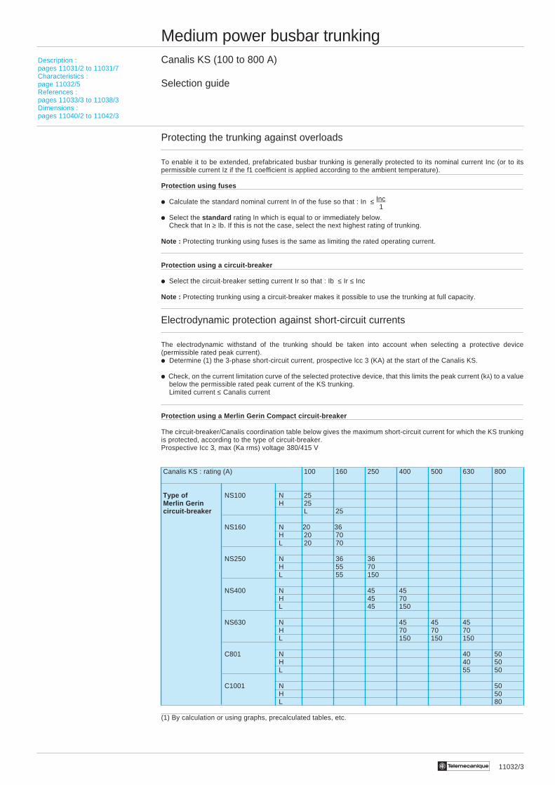
Protection using a Merlin Gerin Compact circuit-breaker
The circuit-breaker/Canalis coordination table below gives the maximum short-circuit current for which the KS trunkingis protected, according to the type of circuit-breaker.Prospective Icc 3, max (Ka rms) voltage 380/415 V
Canalis KS : rating (A) 100 160 250 400 500 630 800
Type of NS100 N 25 Merlin Gerin H 25 circuit-breaker L 25
NS160 N 20 36H 20 70L 20 70
NS250 N 36 36H 55 70L 55 150
NS400 N 45 45H 45 70L 45 150
NS630 N 45 45 45H 70 70 70L 150 150 150
C801 N 40 50H 40 50L 55 50
C1001 N 50H 50L 80
(1) By calculation or using graphs, precalculated tables, etc.
11032/4 Te
Medium power busbar trunkingCanalis KS (100 to 800 A)
Selection guide
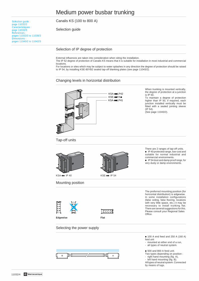
Selection of IP degree of protection
External influences are taken into consideration when siting the installation.The IP 52 degree of protection of Canalis KS means that it is suitable for installation in most industrial and commerciallocations.For locations or sites which may be subject to water splashes in any direction the degree of protection should be raisedto IP 54, by installing KSE-80YB2 sealed tap-off blanking plates (see page 11043/2).
Changing levels in horizontal distribution
When trunking is mounted vertically,the degree of protection at a junctionis IP 50.To maintain a degree of protectionhigher than IP 50, if required, eachjunction installed vertically must befitted with a sealed jointing sleeve(IP 54).(See page 11043/2).
Tap-off units
There are 2 ranges of tap-off units.i IP 40 protected range, low-cost andsuitable for normal industrial andcommercial environments.i IP 54 dust and damp proof range, forvery dusty or damp environments.
KSA-ii IP 40 KSE-ii IP 54n
Mounting position
The preferred mounting position (forhorizontal distribution) is edgewise.In some installation configurations(false ceiling, false flooring, locationswith very little space, etc.) it may benecessary to install trunking flat.There are several suggestions for this.Please consult your Regional SalesOffice.
Selecting the power supply
i 100 A end feed and 250 A (160 A)feed unit- mounted at either end of a run,- all types of neutral system.
i 500 and 800 A feed unit.Two types depending on position :- right hand mounting (fig. A),- left hand mounting (fig. B).All types of neutral system. Connectedby means of lugs.
B A
n
Selection guide :page 11032/2Caracteristiques :page 11032/5References :pages 11033/3 to 11038/3Dimensions :pages 11040/2 to 11042/3
Edgewise Flat
KSA-LP41KSE-YAiKSA-LP42

11032/5Te
Description :pages 11031/2 to 11031/7Selection guide :page 11032/2References :pages 11033/3 to 11038/3Dimensions :pages 11040/2 to 11042/3
Medium power busbar trunkingCanalis KS (100 to 800 A)
Characteristics (1)
Type of trunking KSA-10 KSA-16 KSA-25 KSA-40 KSA-50 KSA-63 KSA-80
General Characteristics
Number of live conductors 3 or 4 3 or 4 3 or 4 3 or 4 3 or 4 3 or 4 3 or 4
Rated thermal current lth A 100 160 250 400 500 630 800
Rated insulation voltage V 660 660 660 660 660 660 660conforming to IEC 158-1
Rated operating voltage V 660 660 660 660 660 660 660
Rated frequency Hz 50/60 50/60 50/60 50/60 50/60 50/60 50/60
Conductor characteristics
Live conductorsRb0phAverage resistance per mΩ/m 1.059 0.490 0.216 0.142 0.091 0.074 0.045conductor, cold state(ambient temperature 20 °C)
Rb1phAverage resistance per mΩ/m 1.395 0.661 0.294 0.190 0.123 0.101 0.061conductor at Ith(ambient temperature 35 °C)
XphAverage reactance per mΩ/m 0.457 0.233 0.192 0.112 0.116 0.070 0.071conductor
ZphAverage impedance per mΩ/m 1.468 0.701 0.351 0.221 0.170 0.123 0.094conductor
Protective conductorCross-section (copper equivalent) mm 2 66 78 78 127 127 247 247
Average resistance, cold state mΩ/m 0.270 0.230 0.230 0.142 0.142 0.074 0.074(ambient temperature 20 °C)
Fault loop impedance at 6 IthBetween live conductors mΩ/m 3.384 1.708 0.811 0.541 0.428 0.279 0.237
Between live conductors and PE mΩ/m 2.090 1.139 0.720 0.512 0.439 0.317 0.289
Other Characteristics
Short-circuit withstand capacityPermissible rated peak current kA 13.6 22 28 49.2 55 67.5 78.7(3-phase)
Permissible rated short time current kA rms 8 11 14 24.6 27.1 32.5 38.3(0.1 s)
Maximum thermal limit A2s 6.8.106 20.2.106 100.106 354.106 733.106 1096.106 1798.106
Degree of protection In normal mounting position. Horizontal, edgewise installation.Standard IP 52 IP 52 IP 52 IP 52 IP 52 IP 52 IP 52With sealing accessories IP 54 IP 54 IP 54 IP 54 IP 54 IP 54 IP 54
Other positions : horizontal installation, flat, vertical installation.Standard IP 50 IP 50 IP 50 IP 50 IP 50 IP 50 IP 50With sealing accessories IP 54 IP 54 IP 54 IP 54 IP 54 IP 54 IP 54
Voltage drop Composite voltage drop, hot state, expressed in V/100 m/A for 3-phase 50 Hz current, with load distributed along therun. Where the load is concentrated at the end of the feed run, the voltage drops are twice the values indicated in thetable.
For a power factor 0.7 V/100 m/A 0.112 0.055 0.030 0.0184 0.0146 0.0104 0.0081cos ϕ of 0.8 V/100 m/A 0.120 0.058 0.030 0.0190 0.0146 0.0106 0.0079
0.9 V/100 m/A 0.126 0.060 0.030 0.0190 0.0140 0.0105 0.00741.0 V/100 m/A 0.121 0.057 0.025 0.0164 0.0107 0.0087 0.0053
Determination of permissible current Derating or uprating factor to be applied to the rated thermal current of the trunkingwhere the average daily ambientlz for a busbar trunking system, temperature is other than 35 °C.according to ambient temperature
Average ambient temperature °C 10 15 20 25 30 35 40 45 50 55 60Factor f1 1,10 1,08 1,06 1,04 1,02 1,00 0,97 0,94 0,91 0,88 0,85
(1) Conforming to international standard IEC 439-2 and European standard EN 60439.2
Te11033/2
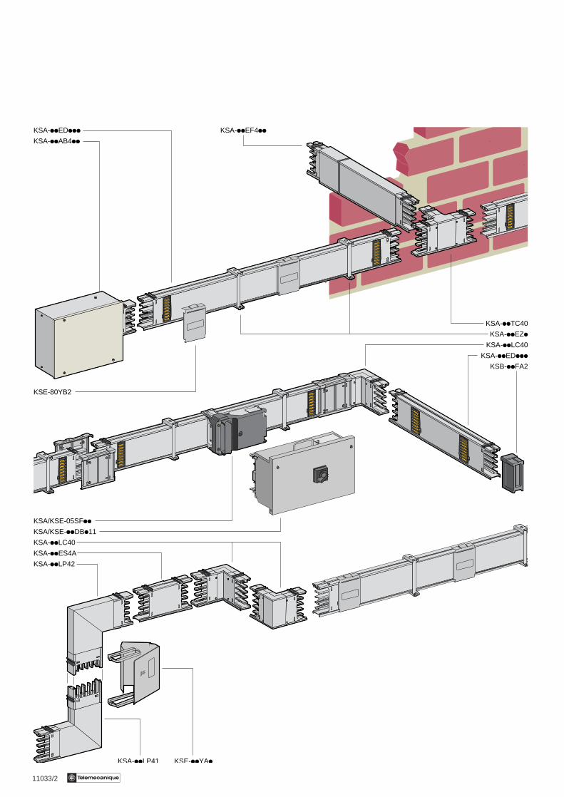
KSA-iiEDiii KSA-iiEF4ii
KSA-iiAB4ii
KSA-iiEZi
KSA-iiTC40
KSA-iiLC40
KSA-iiEDiii
KSB-iiFA2
KSA/KSE-05SFii
KSA-iiLC40
KSA-iiLP42
KSA-iiES4A
KSE-80YB2
KSA-iiLP41 KSE-iiYAi
KSA/KSE-iiDBi11
11033/3Te
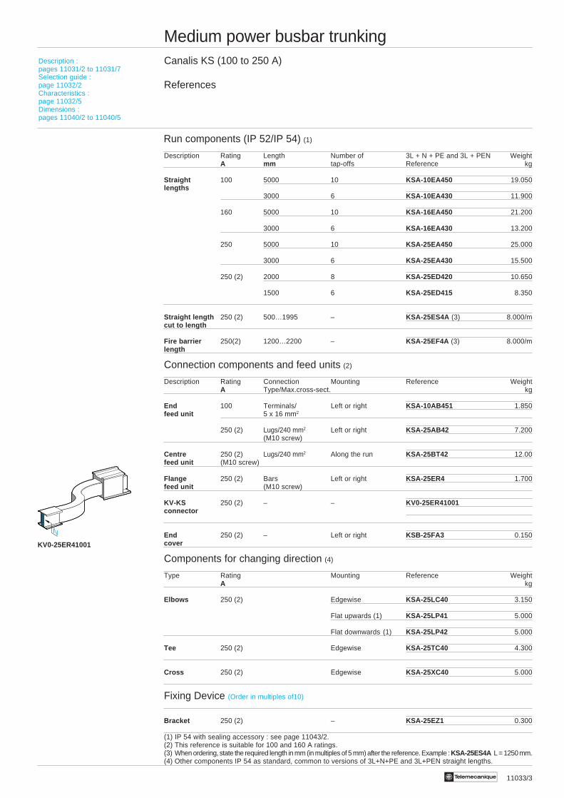
Medium power busbar trunkingCanalis KS (100 to 250 A)
References
Run components (IP 52/IP 54) (1)
Description Rating Length Number of 3L + N + PE and 3L + PEN WeightA mm tap-offs Reference kg
Straight 100 5000 10 KSA-10EA450 19.050lengths
3000 6 KSA-10EA430 11.900
160 5000 10 KSA-16EA450 21.200
3000 6 KSA-16EA430 13.200
250 5000 10 KSA-25EA450 25.000
3000 6 KSA-25EA430 15.500
250 (2) 2000 8 KSA-25ED420 10.650
1500 6 KSA-25ED415 8.350
Straight length 250 (2) 500…1995 – KSA-25ES4A (3) 8.000/mcut to length
Fire barrier 250(2) 1200…2200 – KSA-25EF4A (3) 8.000/mlength
Connection components and feed units (2)
Description Rating Connection Mounting Reference WeightA Type/Max.cross-sect. kg
End 100 Terminals/ Left or right KSA-10AB451 1.850feed unit 5 x 16 mm2
250 (2) Lugs/240 mm2 Left or right KSA-25AB42 7.200(M10 screw)
Centre 250 (2) Lugs/240 mm2 Along the run KSA-25BT42 12.00feed unit (M10 screw)
Flange 250 (2) Bars Left or right KSA-25ER4 1.700feed unit (M10 screw)
KV-KS 250 (2) – – KV0-25ER41001connector
End 250 (2) – Left or right KSB-25FA3 0.150cover
Components for changing direction (4)
Type Rating Mounting Reference WeightA kg
Elbows 250 (2) Edgewise KSA-25LC40 3.150
Flat upwards (1) KSA-25LP41 5.000
Flat downwards (1) KSA-25LP42 5.000
Tee 250 (2) Edgewise KSA-25TC40 4.300
Cross 250 (2) Edgewise KSA-25XC40 5.000
Fixing Device (Order in multiples of10)
Bracket 250 (2) – KSA-25EZ1 0.300
(1) IP 54 with sealing accessory : see page 11043/2.(2) This reference is suitable for 100 and 160 A ratings.(3) When ordering, state the required length in mm (in multiples of 5 mm) after the reference. Example : KSA-25ES4A L = 1250 mm.(4) Other components IP 54 as standard, common to versions of 3L+N+PE and 3L+PEN straight lengths.
N
Description :pages 11031/2 to 11031/7Selection guide :page 11032/2Characteristics :page 11032/5Dimensions :pages 11040/2 to 11040/5
KV0-25ER41001
11033/4 Te
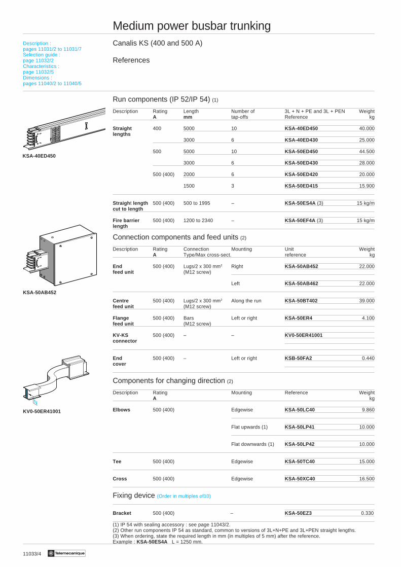
Medium power busbar trunkingCanalis KS (400 and 500 A)
References
Run components (IP 52/IP 54) (1)
Description Rating Length Number of 3L + N + PE and 3L + PEN WeightA mm tap-offs Reference kg
Straight 400 5000 10 KSA-40ED450 40.000lengths
3000 6 KSA-40ED430 25.000
500 5000 10 KSA-50ED450 44.500
3000 6 KSA-50ED430 28.000
500 (400) 2000 6 KSA-50ED420 20.000
1500 3 KSA-50ED415 15.900
Straigh t length 500 (400) 500 to 1995 – KSA-50ES4A (3) 15 kg/mcut to length
Fire barrier 500 (400) 1200 to 2340 – KSA-50EF4A (3) 15 kg/mlength
Connection components and feed units (2)
Description Rating Connection Mounting Unit WeightA Type/Max cross-sect. reference kg
End 500 (400) Lugs/2 x 300 mm2 Right KSA-50AB452 22.000feed unit (M12 screw)
Left KSA-50AB462 22.000
Centre 500 (400) Lugs/2 x 300 mm2 Along the run KSA-50BT402 39.000feed unit (M12 screw)
Flange 500 (400) Bars Left or right KSA-50ER4 4.100feed unit (M12 screw)
KV-KS 500 (400) – – KV0-50ER41001connector
End 500 (400) – Left or right KSB-50FA2 0.440cover
Components for changing direction (2)
Description Rating Mounting Reference WeightA kg
Elbows 500 (400) Edgewise KSA-50LC40 9.860
Flat upwards (1) KSA-50LP41 10.000
Flat downwards (1) KSA-50LP42 10.000
Tee 500 (400) Edgewise KSA-50TC40 15.000
Cross 500 (400) Edgewise KSA-50XC40 16.500
Fixing device (Order in multiples of10)
Bracket 500 (400) – KSA-50EZ3 0.330
(1) IP 54 with sealing accessory : see page 11043/2.(2) Other run components IP 54 as standard, common to versions of 3L+N+PE and 3L+PEN straight lengths.(3) When ordering, state the required length in mm (in multiples of 5 mm) after the reference.Example : KSA-50ES4A L = 1250 mm.
Description :pages 11031/2 to 11031/7Selection guide :page 11032/2Characteristics :page 11032/5Dimensions :pages 11040/2 to 11040/5
KSA-50AB452
KSA-40ED450
N
KV0-50ER41001

11033/5Te
Medium power busbar trunkingCanalis KS (630 and 800 A)
References
Run components (IP 52/IP 54) (1)
Description Rating Length Number of 3L + N + PE and 3L + PEN WeightA mm tap-offs Reference kg
Straight 630 5000 10 KSA-63ED450 58.500lengths
3000 6 KSA-63ED430 36.200
800 5000 10 KSA-80ED450 70.000
3000 6 KSA-80ED430 43.500
800 (630) 2000 6 KSA-80ED420 30.600
1500 3 KSA-80ED415 24.000
Straight length 800 (630) 500 to 1995 – KSA-80ES4A (3) 19.600/mcut to length
Fire barrier 800 (630) 1200 to 2340 – KSA-80EF4A (3) 19.600/mlength
Connection components and feed units (2)
Description Rating Connection Mounting Reference WeightA Type/Max cross-sect. kg
End 800 (630) Lugs/3 x 300 mm2 Right KSA-80AB452 36.200feed unit (M12 screw)
Left KSA-80AB462 36.200
Centre 800 (630) Lugs/3 x 300 mm2 Along the run KSA-80BT402 40.000feed unit (M12 screw)
Flange 800 (630) Bars Left or right KSA-80ER4 6.150feed unit (4 x M10 screw)
KV-KS 800 (630) – – KV0-80ER41001connector
End 800 (630) – – KSB-80FA2 0.510cover
Components for changing direction (2)
Description Rating Mounting Reference WeightA kg
Elbows 800 (630) Edgewise KSA-80LC40 15.000
Flat upwards (1) KSA-80LP41 13.700
Flat downwards (1) KSA-80LP42 13.700
Tee 800 (630) Edgewise KSA-80TC40 18.240
Cross 800 (630) Edgewise KSA-80XC40 20.000
Fixing device (Order in multiples of 10)
Bracket 800 (630) – KSA-80EZ3 0.400
(1) IP 54 with sealing accessory : see page 11043/2.(2) Other run components IP 54 as standard, common to versions of 3L+ N + PE and 3L+ PEN straight lengths.(3) When ordering, state the required length in mm (in multiples of 5 mm) after the reference.Example : KSA-80ES4A L = 1250 mm.
Description :pages 11031/2 to 11031/7Selection guide :page 11032/2Characteristics :page 11032/5Dimensions :pages 11040/2 to 11040/5
KSA-63ED450
KSA-80AB452
N
KV0-80ER41001
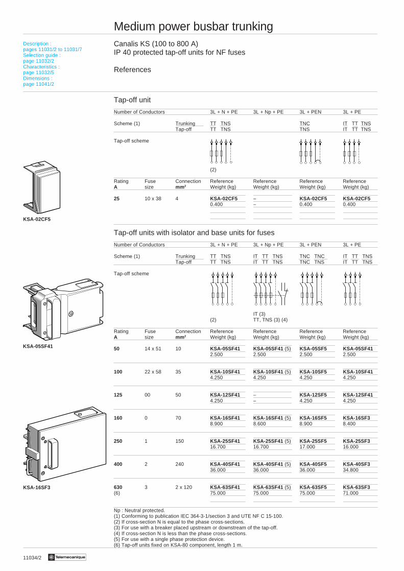
11034/2 Te
Medium power busbar trunkingCanalis KS (100 to 800 A)IP 40 protected tap-off units for NF fuses
References
Tap-off unit
Number of Conductors 3L + N + PE 3L + Np + PE 3L + PEN 3L + PE
Scheme (1) Trunking TT TNS TNC IT TT TNSTap-off TT TNS TNS IT TT TNS
Tap-off scheme
(2)
Rating Fuse Connection Reference Reference Reference ReferenceA size mm 2 Weight (kg) Weight (kg) Weight (kg) Weight (kg)
25 10 x 38 4 KSA-02CF5 – KSA-02CF5 KSA-02CF50.400 – 0.400 0.400
Tap-off units with isolator and base units for fuses
Number of Conductors 3L + N + PE 3L + Np + PE 3L + PEN 3L + PE
Scheme (1) Trunking TT TNS IT TT TNS TNC TNC IT TT TNSTap-off TT TNS IT TT TNS TNC TNS IT TT TNS
Tap-off scheme
IT (3)(2) TT, TNS (3) (4)
Rating Fuse Connection Reference Reference Reference ReferenceA size mm 2 Weight (kg) Weight (kg) Weight (kg) Weight (kg)
50 14 x 51 10 KSA-05SF41 KSA-05SF41 (5) KSA-05SF5 KSA-05SF412.500 2.500 2.500 2.500
100 22 x 58 35 KSA-10SF41 KSA-10SF41 (5) KSA-10SF5 KSA-10SF414.250 4.250 4.250 4.250
125 00 50 KSA-12SF41 – KSA-12SF5 KSA-12SF414.250 – 4.250 4.250
160 0 70 KSA-16SF41 KSA-16SF41 (5) KSA-16SF5 KSA-16SF38.900 8.600 8.900 8.400
250 1 150 KSA-25SF41 KSA-25SF41 (5) KSA-25SF5 KSA-25SF316.700 16.700 17.000 16.000
400 2 240 KSA-40SF41 KSA-40SF41 (5) KSA-40SF5 KSA-40SF336.000 36.000 36.000 34.800
630 3 2 x 120 KSA-63SF41 KSA-63SF41 (5) KSA-63SF5 KSA-63SF3(6) 75.000 75.000 75.000 71.000
Np : Neutral protected.(1) Conforming to publication IEC 364-3-1/section 3 and UTE NF C 15-100.(2) If cross-section N is equal to the phase cross-sections.(3) For use with a breaker placed upstream or downstream of the tap-off.(4) If cross-section N is less than the phase cross-sections.(5) For use with a single phase protection device.(6) Tap-off units fixed on KSA-80 component, length 1 m.
KSA-16SF3
KSA-02CF5
KSA-05SF41
Description :pages 11031/2 to 11031/7Selection guide :page 11032/2Characteristics :page 11032/5Dimensions :page 11041/2
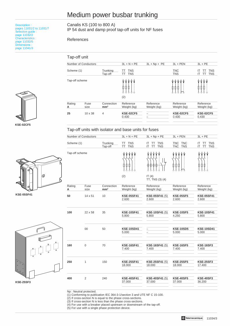
11034/3Te
Medium power busbar trunkingCanalis KS (100 to 800 A)IP 54 dust and damp proof tap-off units for NF fuses
References
Tap-off unit
Number of Conductors 3L + N + PE 3L + Np + PE 3L + PEN 3L + PE
Scheme (1) Trunking TT TNS TNC IT TT TNSTap-off TT TNS TNS IT TT TNS
Tap-off scheme
(2)
Rating Fuse Connection Reference Reference Reference ReferenceA size mm 2 Weight (kg) Weight (kg) Weight (kg) Weight (kg)
25 10 x 38 4 KSE-02CF5 – KSE-02CF5 KSE-02CF50.430 – 0.430 0.430
Tap-off units with isolator and base units for fuses
Number of Conductors 3L + N + PE 3L + Np + PE 3L + PEN 3L + PE
Scheme (1) Trunking TT TNS IT TT TNS TNC TNC IT TT TNSTap-off TT TNS IT TT TNS TNC TNS IT TT TNS
Tap-off scheme
(2) IT (4)TT, TNS (3) (4)
Rating Fuse Connection Reference Reference Reference ReferenceA size mm 2 Weight (kg) Weight (kg) Weight (kg) Weight (kg)
50 14 x 51 10 KSE-05SF41 KSE-05SF41 (5) KSE-05SF5 KSE-05SF412.600 2.600 2.600 2.600
100 22 x 58 35 KSE-10SF41 KSE-10SF41 (5) KSE-10SF5 KSE-10SF415.800 5.800 4.250 5.800
00 50 KSE-10SD41 – KSE-10SD5 KSE-10SD415.000 – 5.000 5.000
160 0 70 KSE-16SF41 KSE-16SF41 (5) KSE-16SF5 KSE-16SF37.400 7.400 7.400 7.400
250 1 150 KSE-25SF41 KSE-25SF41 (5) KSE-25SF5 KSE-25SF318.000 18.000 18.000 17.400
400 2 240 KSE-40SF41 KSE-40SF41 (5) KSE-40SF5 KSE-40SF337.000 37.000 37.000 36.200
Np : Neutral protected.(1) Conforming to publication IEC 364-3-1/section 3 and UTE NF C 15-100.(2) If cross-section N is equal to the phase cross-sections.(3) If cross-section N is less than the phase cross-sections.(4) For use with a breaker placed upstream or downstream of the tap-off.(5) For use with a single phase protection device.
Description :pages 11031/2 to 11031/7Selection guide :page 11032/2Characteristics :page 11032/5Dimensions :page 11041/3
KSE-02CF5
KSE-25SF3
KSE-05SF41
11035/2 Te
Medium power busbar trunkingCanalis KS (100 to 800 A)IP 54 dust and damp proof tap-off units for DIN and BS fuses
References
Tap-off units
Number of conductors 3L + N + PE 3L + PEN 3L + PE
Scheme (1) Trunking TT TNS TNC IT TT TNSTap-off TT TNS TNS IT TT TNS
Tap-off scheme
For Rating Type of Connection Reference Reference Referencefuses A fuses mm 2 Weight (kg) Weight (kg) Weight (kg)
DIN 16 D01 4 KSE-02CD5 KSE-02CD5 KSE-02CD5Neozed E14 0.450 0.450 0.450
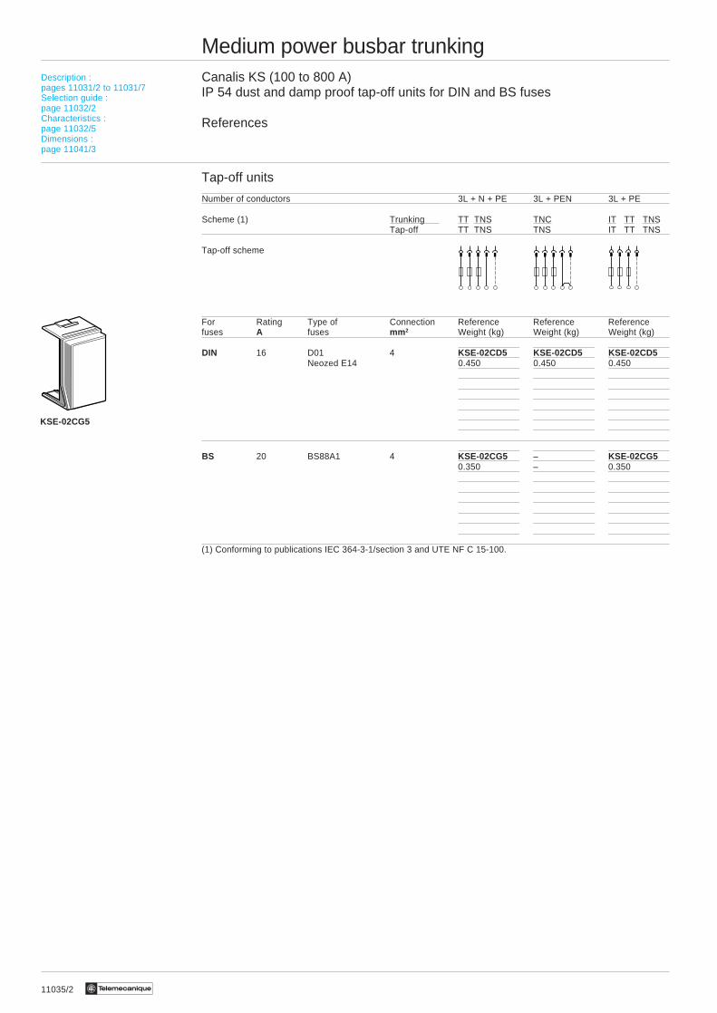
BS 20 BS88A1 4 KSE-02CG5 – KSE-02CG50.350 – 0.350
(1) Conforming to publications IEC 364-3-1/section 3 and UTE NF C 15-100.
Description :pages 11031/2 to 11031/7Selection guide :page 11032/2Characteristics :page 11032/5Dimensions :page 11041/3
KSE-02CG5
11035/3Te
Medium power busbar trunkingCanalis KS (100 to 800 A)IP 54 dust and damp proof tap-off units for DIN and BS fuses
References
Tap-off units with isolator and base units for fuses
Number of conductors 3L + N + PE 3L + PEN 3L + PE
Scheme (1) Trunking TT TNS TNC TNC IT TT TNSTap-off TT TNS TNC TNS IT TT TNS
Tap-off scheme
(2)
For Rating Type of Connection Reference Reference Referencefuses A fuses mm 2 Weight (kg) Weight (kg) Weight (kg)
DIN 25 Diazed E27 6 KSE-02SD41 KSE-02SD5 KSE-02SD412.720 2.720 2.720
50 D02 10 KSE-05SD41 KSE-05SD5 KSE-05SD41Neozed E18 2.600 2.600 2.600
63 Diazed E33 16 KSE-06SD41 KSE-06SD5 KSE-06SD415.300 5.300 5.300
100 Size 00 50 KSE-10SD41 KSE-10SD5 KSE-10SD415.000 5.000 5.000
160 Size 00 50 KSE-16SD41 KSE-16SD5 KSE-16SD37.400 7.400 7.400
250 Size 1 150 KSE-25SF41 KSE-25SF5 KSE-25SF318.000 18.000 17.400
400 Size 2 240 KSE-40SF41 KSE-40SF5 KSE-40SF337.000 37.000 36.200
BS 30 (3) BS88A1 6 KSE-03SG41 – KSE-03SG412.600 – 2.600
60 BS88A1 or A3 35 KSE-06SG41 – KSE-06SG415.000 – 5.000
160 BS88B1 or B2 70 KSE-16SG41 – KSE-16SG417.400 – 7.400
(1) Conforming to publications IEC 364-3-1/section 3 and UTE NF C 15-100.(2) If the neutral cross-section is equal to the phase cross-sections.(3) Do not use with scheme TNC
TNC
Description :pages 11031/2 to 11031/7Selection guide :page 11032/2Characteristics :page 11032/5Dimensions :page 11041/3
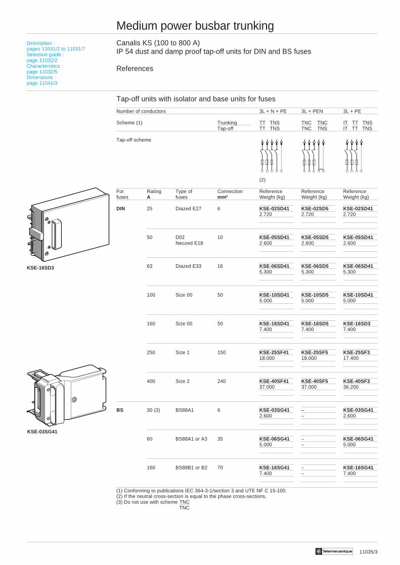
KSE-16SD3
KSE-03SG41
11037/2 Te
Medium power busbar trunkingCanalis KS (100 to 800 A)Tap-off units for IP 40 protected equipment
References
Tap-off units for modular equipment (not supplied)
Number of conductors 3L + N + PE 3L + Np + PE 3L + PEN 3L + PE
Scheme (1) Trunking TT TNS IT TT TNS TNC IT TT TNSTap-off TT TNS IT TT TNS TNS IT TT TNS
Tap-off scheme(Example with circuit-breaker)
(2)
Rating Number Reference Reference Reference ReferenceA of modules Weight (kg) Weight (kg) Weight (kg) Weight (kg)
25 4 KSA-02DA50010 KSA-02DA50010 KSA-02DA50010 KSA-02DA500100.500 0.500 0.500 0.500
Tap-off units with isolator
Number of conductors 3L + N + PE 3L + Np + PE 3L + PEN 3L + PE
Scheme (1) Trunking TT TNS IT TT TNS TNC TNC IT TT TNSTap-off TT TNS IT TT TNS TNC TNS IT TT TNS
Tap-off scheme(Example with circuit-breaker)
(2)
For modular equipment (not supplied)Rating Number Reference Reference Reference ReferenceA of modules Weight (kg) Weight (kg) Weight (kg) Weight (kg)
50 7.5 KSA-05DA40010 KSA-05DA40010 KSA-05DA50010 KSA-05DA400102.400 2.400 2.400 2.400
100 11 KSA-10DB40030 KSA-10DB40030 KSA-10DB50030 KSA-10DB400305.000 5.000 5.000 5.000
For contact breakers (not supplied)With Telequick plate Reference Reference Reference ReferenceType Weight (kg) Weight (kg) Weight (kg) Weight (kg)
AM1-PA3030 KSA-12SU411 – KSA-12SU511 –
AM1-PA6040 KSA-12SU412 – KSA-12SU512 –
Np : Neutral protected.(1) Conforming to publications IEC 364-3-1/section 3 and UTE NF C 15-100.(2) If the neutral cross-section is equal to the phase cross-sections.
Description :pages 11031/2 to 11031/7Selection guide :page 11032/2Characteristics :page 11032/5Dimensions :page 11042/2
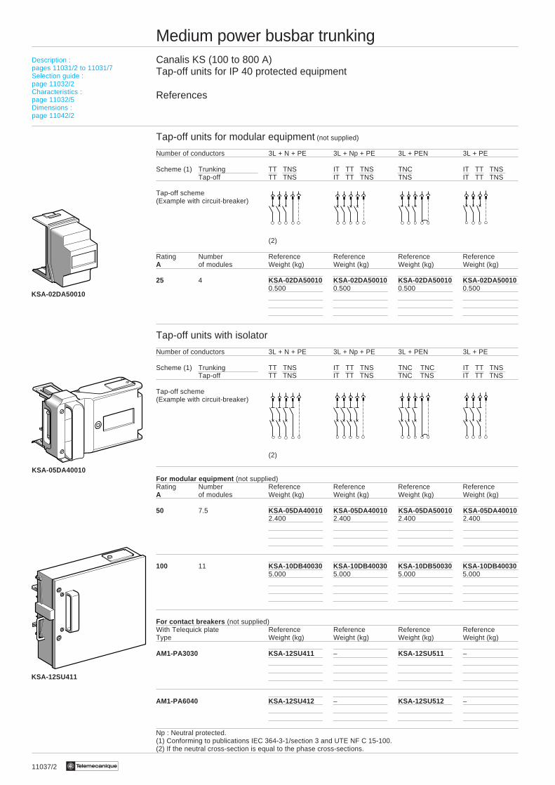
KSA-02DA50010
KSA-05DA40010
KSA-12SU411
11037/3Te
Medium power busbar trunkingCanalis KS (100 to 800 A)Tap-off units for IP 54 dust and damp proof equipment
References
Tap-off units with isolator for modular equipment (not supplied)
Number of conductors 3L + N + PE 3L + Np + PE 3L + PEN 3L + PE
Scheme (1) Trunking TT TNS IT TT TNS TNC TNC IT TT TNSTap-off TT TNS IT TT TNS TNC TNS IT TT TNS
Tap-off scheme(Example with circuit-breaker)
(2)
Rating Number Reference Reference Reference ReferenceA of modules Weight (kg) Weight (kg) Weight (kg) Weight (kg)
50 7.5 KSE-05DA4 KSE-05DA4 KSE-05DA5 KSE-05DA42.400 2.400 2.400 2.400
100 7.5 KSE-10DA4 KSE-10DA4 KSE-10DA5 KSE-10DA43.400 3.400 3.400 3.400
Np : Neutral protected.(1) Conforming to publications IEC 364-3-1/section 3 and UTE NF C 15-100.(2) If the neutral cross-section is equal to the phase cross-sections.
Description :pages 11031/2 to 11031/7Selection guide :page 11032/2Characteristics :page 11032/5Dimensions :page 11042/3
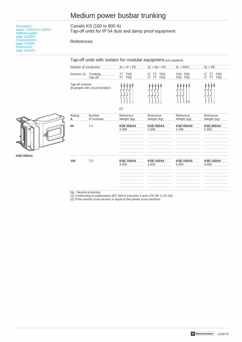
KSE-05DA4
11038/2 Te
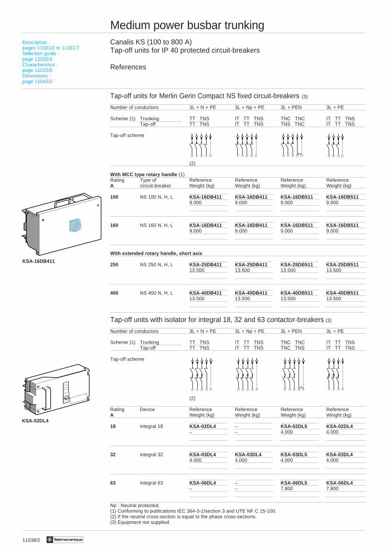
Medium power busbar trunkingCanalis KS (100 to 800 A)Tap-off units for IP 40 protected circuit-breakers
References
Tap-off units for Merlin Gerin Compact NS fixed circuit-breakers (3)
Number of conductors 3L + N + PE 3L + Np + PE 3L + PEN 3L + PE
Scheme (1) Trunking TT TNS IT TT TNS TNC TNC IT TT TNSTap-off TT TNS IT TT TNS TNS TNC IT TT TNS
Tap-off scheme
(2)
With MCC type rotary handle (1)Rating Type of Reference Reference Reference ReferenceA circuit-breaker Weight (kg) Weight (kg) Weight (kg) Weight (kg)
100 NS 100 N, H, L KSA-16DB411 KSA-16DB411 KSA-16DB511 KSA-16DB5119.000 9.000 9.000 9.000
160 NS 160 N, H, L KSA-16DB411 KSA-16DB411 KSA-16DB511 KSA-16DB5119.000 9.000 9.000 9.000
With extended rotary handle, short axis
250 NS 250 N, H, L KSA-25DB411 KSA-25DB411 KSA-25DB511 KSA-25DB51113.500 13.500 13.500 13.500
400 NS 400 N, H, L KSA-40DB411 KSA-40DB411 KSA-40DB511 KSA-40DB51113.500 13.500 13.500 13.500
Tap-off units with isolator for integral 18, 32 and 63 contactor-breakers (3)
Number of conductors 3L + N + PE 3L + Np + PE 3L + PEN 3L + PE
Scheme (1) Trunking TT TNS IT TT TNS TNC TNC IT TT TNSTap-off TT TNS IT TT TNS TNC TNS IT TT TNS
Tap-off scheme
(2)
Rating Device Reference Reference Reference ReferenceA Weight (kg) Weight (kg) Weight (kg) Weight (kg)
18 integral 18 KSA-02DL4 – KSA-02DL5 KSA-02DL4– – 4.000 4.000
32 integral 32 KSA-03DL4 KSA-03DL4 KSA-03DL5 KSA-03DL44.000 4.000 4.000 4.000
63 integral 63 KSA-06DL4 – KSA-06DL5 KSA-06DL4– – 7.800 7.800
Np : Neutral protected.(1) Conforming to publications IEC 364-3-1/section 3 and UTE NF C 15-100.(2) If the neutral cross-section is equal to the phase cross-sections.(3) Equipment not supplied.
Description :pages 11031/2 to 11031/7Selection guide :page 11032/2Characteristics :page 11032/5Dimensions :page 11042/2
KSA-02DL4
KSA-16DB411

11038/3Te
Medium power busbar trunkingCanalis KS (100 to 800 A)Tap-off units for IP 54 dust and damp proof circuit-breakers
References
Tap-off units for Merlin Gerin Compact NS fixed circuit-breaker (3)
With extended rotary handle, short axis (1)Number of conductors 3L + N + PE 3L + Np + PE 3L + PEN 3L + PE
Scheme (1) Trunking TT TNS IT TT TNS TNC TNC IT TT TNSTap-off TT TNS IT TT TNS TNS TNC IT TT TNS
Tap-off scheme
(2)
Rating Type of Reference Reference Reference ReferenceA circuit-breaker Weight (kg) Weight (kg) Weight (kg) Weight (kg)
100 NS 100 N, H, L KSE-16DB411 KSE-16DB411 KSE-16DB511 KSE-16DB51111.000 11.000 11.000 11.000
160 NS 160 N, H, L KSE-16DB411 KSE-16DB411 KSE-16DB511 KSE-16DB51111.000 11.000 11.000 11.000
250 NS 250 N, H, L KSE-25DB411 KSE-25DB411 KSE-25DB511 KSE-25DB51113.500 13.500 13.500 13.500
400 NS 400 N, H, L KSE-40DB411 KSE-40DB411 KSE-40DB511 KSE-40DB51113.500 13.500 13.500 13.500
Tap-off units with isolator for integral 18, 32 and 63 contactor-breakers (3)
With non-adjustable handle on door, for dust and damp proof units (1)Number of conductors 3L + N + PE 3L + Np + PE 3L + PEN 3L + PE
Scheme (1) Trunking TT TNS IT TT TNS TNC TNC IT TT TNSTap-off TN TNS IT TT TNS TNC TNS IT TT TNS
Tap-off scheme
(2)
Rating Device Reference Reference Reference ReferenceA Weight (kg) Weight (kg) Weight (kg) Weight (kg)
18 integral 18 KSE-02DL4 – KSE-02DL5 KSE-02DL4– – 4.000 4.000
32 integral 32 KSE-03DL4 KSE-03DL4 KSE-03DL5 KSE-03DL44.000 4.000 4.000 4.000
63 integral 63 KSE-06DL4 – KSE-06DL5 KSE-06DL4– – 7.800 7.800
Np : Neutral protected.(1) Conforming to publications IEC 364-3-1/section 3 and UTE NF C 15-100.(2) If the neutral cross-section is equal to the phase cross-sections.(3) Equipment not supplied.
Description :pages 11031/2 to 11031/7Selection guide :page 11032/2Characteristics :page 11032/5Dimensions :page 11042/3
KSE-16DB411
KSE-02DL4

11043/2 Te
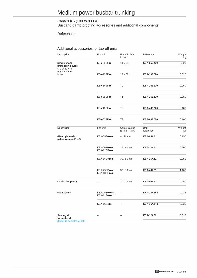
Medium power busbar trunkingCanalis KS (100 to 800 A)Dust and damp proofing accessories and additional components
References
IP 54 dust and damp proofing accessories for trunking installed edgewise
Description Rating Use Reference WeightA kg
Tap-off 100 to 800 1 per unused KSE-80YB2 0.080blanking plate tap-off outlet
IP 54 dust and damp proofing accessories for trunking installed flat or vertically
Sealed jointing 250 For straight lengths KSE-25YA2 1.280sleeve (100 to 160) KSA-iiEDiii
(1 per length)
For any other KSE-25YA3 1.280length(1 per length)
500 For any length KSE-50YA2 2.250(400) (1 per length)
800 For any length KSE-80YA2 2.600(630) (1 per length)
Tap-off 100 to 800 1 per unused KSE-80YB2 0.080blanking plate tap-off outlet
Description :page 11031/7Dimensions :page 11040/5
KSE-80YB2
KSE-80YB2
KSE-iiYAi
11043/3Te
Medium power busbar trunkingCanalis KS (100 to 800 A)Dust and damp proofing accessories and additional components
References
Additional accessories for tap-off units
Description For unit For NF blade Reference Weightfuses kg
Single phase KSi-05SFii 14 x 51 KSA-05EZ20 0.020protection device(3L or 3L + N)For NF bladefuses KSi-10SFii 22 x 58 KSA-10EZ20 0.020
KSi-16SFii T0 KSA-16EZ20 0.050
KSi-25SFii T1 KSA-25EZ20 0.050
KSi-40SFii T2 KSA-40EZ20 0.100
KSi-63SFii T3 KSA-63EZ20 0.100
Description For unit Cable clamps Unit WeightØ min. - max. reference kg
Gland plate with KSA-05Siiii 8...20 mm KSA-05AZ1 0.150cable clamps (IP 40)
KSA-06Siiii 25...40 mm KSA-12AZ1 0.200KSA-12SFiii
KSA-16Siiii 30...55 mm KSA-16AZ1 0.250
KSA-25SFiii 30...70 mm KSA-40AZ1 1.100KSA-40SFiii
Cable clamp only – 30...70 mm KSA-80AZ1 0.950
Gate switch KSA-05Siii to – KSA-12AZ40 0.015KSA-12Siii
KSA-16Siii – KSA-16AZ40 0.030
Sealing kit – – KSA-12AZ2 0.010for unit end(Order in multiples of 20)

Te11040/2
Medium power busbar trunkingCanalis KS (100 to 800 A)
Dimensions
Trunking lengths 100, 160 and 250 AKSA-10EAiii, KSA-16EA iii and KSA-25EA iii
Trunking lengths 400, 500, 630 and 800 AKSA-40EDiii, KSA-50EDiii, KSA-63EDiii and KSA-80ED iii
Rating (A) a400/500 75630/800 113
Straight lengths cut to length Fire barrier lengthsKSA-i ii ii ii ii iES4A KSA- i ii ii ii ii iEF4A
Rating (A) a Rating (A) a100…250 54 100…250 54400…500 75 400…500 75630 and 800 113 630 and 800 113
(1) Minimum 500, maximum 1995 (1) Minimum 600.(indicate the position of the fire barrier)
Description :pages 11031/2 to 11031/7Selection guide :page 11032/2Characteristics :page 11032/5References :pages 11033/3 to 11033/5
5000
a
146
2501000100010001000750
250 1000 750100010001000
54
146
5000
2501000100010001000750
250 1000 750100010001000
a(1) a(1)
1200 à 2340
(1)
11040/3Te
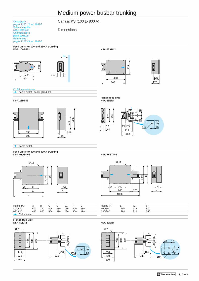
Medium power busbar trunkingCanalis KS (100 to 800 A)
Dimensions
Feed units for 100 and 250 A trunkingKSA-10AB451 KSA-25AB42
(1) 60 mm minimumCable outlet : cable gland 29
Flange feed unitKSA-25BT42 KSA-25ER4
Cable outlet.
Feed units for 400 and 800 A trunkingKSA-iiAB4i2 KSA-iiBT402
Rating (A) A B C D D1 F G Rating (A) a a1 b400/500 600 770 406 230 175 300 150 400/500 290 235 510630/800 680 850 556 310 236 300 190 630/800 390 316 556
Cable outlet.
Flange feed unitKSA-50ER4 KSA-80ER4
Description :pages 11031/2 to 11031/7Selection guide :page 11032/2Characteristics :page 11032/5References :pages 11033/3 to 11033/5
G F
A
B
D
D1
C
C-2
0
Ø 11
1640
40 72
Ø11290
260
210 166
338
370
290
340
8080
80
Ø 7
N
20
37
Ø14143
315
370
290
340
8080
80
Ø 7
N
250
220
170
177 300
660
1000
a
a1
b
b-20
170
Ø 11
(1)
390
284 112
212
505
400
315
170
126
390
600
270
126
170
430
20
37
Ø1445 90 105
143
253
N
81
280
294
494361
61
11040/4 Te
Medium power busbar trunkingCanalis KS (100 to 800 A)
Dimensions
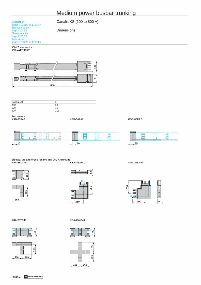
KV-KS connectorKV0-iiER41001
Rating (A) a250 54500 75800 113
End coversKSB-25FA3 KSB-50FA2 KSB-80FA2
Elbows, tee and cross for 100 and 250 A trunkingKSA-25LC40 KSA-25LP41 KSA-25LP42
KSA-25TC40 KSA-25XC40
Description :pages 11031/2 to 11031/7Selection guide :page 11032/2Characteristics :page 11032/5References :pages 11033/3 to 11033/5
165
165
165
N
N
5425
0
250
165
165 165
165N
165
165 165
165N
165
54250
250
250250
N
15 20 20
146
2000
a
11040/5Te
Medium power busbar trunkingCanalis KS (100 to 800 A)
Dimensions
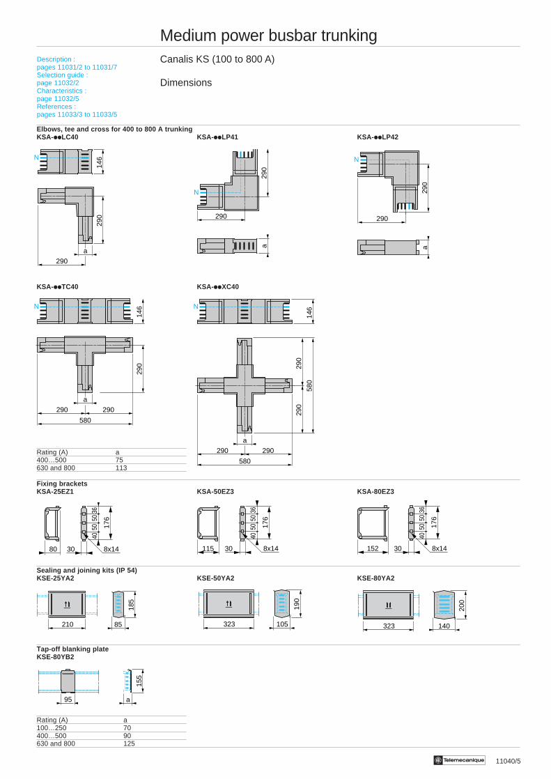
Elbows, tee and cross for 400 to 800 A trunkingKSA-iiLC40 KSA-iiLP41 KSA- iiLP42
KSA-iiTC40 KSA-iiXC40
Rating (A) a400…500 75630 and 800 113
Fixing bracketsKSA-25EZ1 KSA-50EZ3 KSA-80EZ3
Sealing and joining kits (IP 54)KSE-25YA2 KSE-50YA2 KSE-80YA2
Tap-off blanking plateKSE-80YB2
Rating (A) a100…250 70400…500 90630 and 800 125
140
200
32385
185
210 105
190
323
a
155
95
N
146
290
a
290
N
a29
0
290
N
a29
0
290
N
290
146
290 290
580
a
290 290
580
290
290
580
146
a
N
152 30
3650
50 176
8x14
40
80 30
3650
50 176
8x14
40
115 30
3650
50 176
8x14
40
Description :pages 11031/2 to 11031/7Selection guide :page 11032/2Characteristics :page 11032/5References :pages 11033/3 to 11033/5
11041/2 Te
Medium power busbar trunkingCanalis KS (100 to 800 A)Tap-off units with/without isolator and fuse carriers
Dimensions
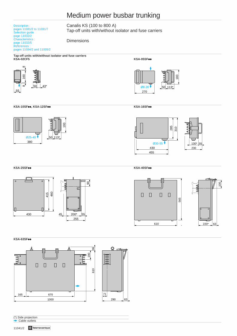
Tap-off units with/without isolator and fuse carriersKSA-02CF5 KSA-05SFii
KSA-10SFii, KSA-12SFii KSA-16SFii
KSA-25SFii KSA-40SFii
KSA-63SFii
(*) Side projection Cable outlets
Description :pages 11031/2 to 11031/7Selection guidepage 11032/2Characteristics :page 11032/5References :pages 11034/2 and 11035/2
430
55130*
285
310
230
455
Ø30-55
270
50 113*
183
Ø8-2093
50 43*
160
88
380
193
50 113*Ø25-40
430 200*
415
460
255
45
90
55
610 220*10
0
565
63
670165
290
610
36
71
631000
190
11041/3Te
Medium power busbar trunkingCanalis KS (100 to 800 A)Dust and damp proof tap-off units with/without isolator and fuse carriersDimensions
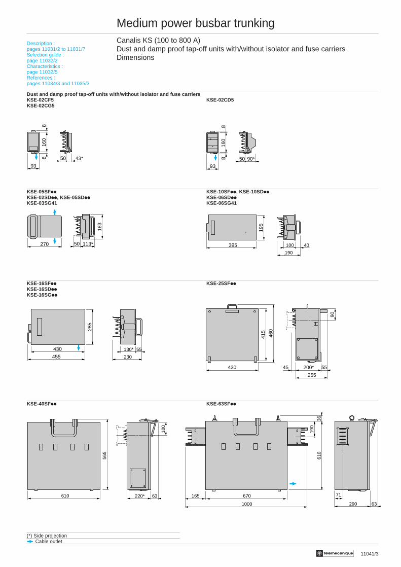
Dust and damp proof tap-off units with/without isolator and fuse carriersKSE-02CF5 KSE-02CD5KSE-02CG5
KSE-05SFii KSE-10SFii, KSE-10SDiiKSE-02SDii, KSE-05SDii KSE-06SDiiKSE-03SG41 KSE-06SG41
KSE-16SFii KSE-25SFiiKSE-16SDiiKSE-16SGii
KSE-40SFii KSE-63SFii
(*) Side projection Cable outlet
Description :pages 11031/2 to 11031/7Selection guide :page 11032/2Characteristics :page 11032/5References :pages 11034/3 and 11035/3
93
50 43*
160
88 90*
93
50
160
88
195
395 40100
190
270 50 113*
183
430 55130*
285
230455
430 200*
415
460
255
45
90
55
610 220*
100
565
63 670165
290
610
36
71
631000
190
11042/2 Te
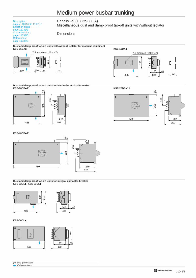
Medium power busbar trunkingCanalis KS (100 to 800 A)Miscellaneous tap-off units with/without isolator
Dimensions
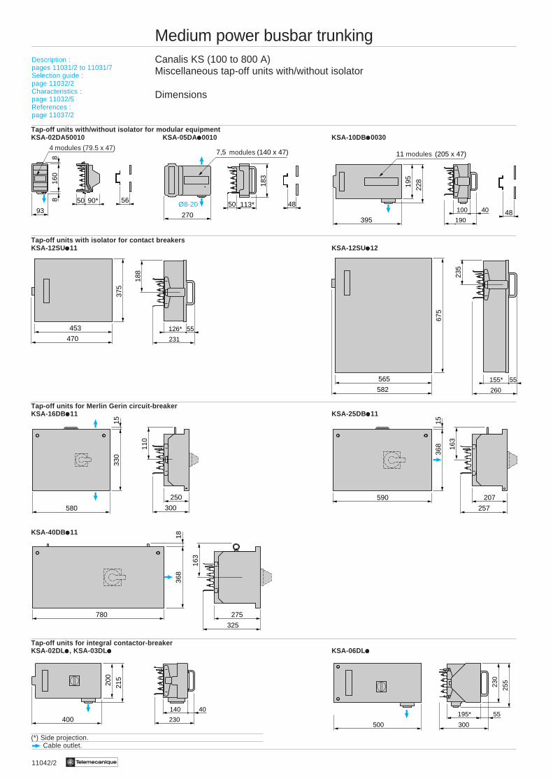
Tap-off units with/without isolator for modular equipmentKSA-02DA50010 KSA-05DA iiiii0010 KSA-10DB iiiii0030
Tap-off units with isolator for contact breakersKSA-12SUiiiii11 KSA-12SUiiiii12
Tap-off units for Merlin Gerin circuit-breakerKSA-16DB iiiii11 KSA-25DB iiiii11
KSA-40DB iiiii11
Tap-off units for integral contactor-breakerKSA-02DL iiiii , KSA-03DL iiiii KSA-06DL iiiii
(*) Side projection. Cable outlet.
Description :pages 11031/2 to 11031/7Selection guide :page 11032/2Characteristics :page 11032/5References :page 11037/2
modules4 modules (79.5 x 47)
modules
500 300
195* 55
230
255
270
50 113*
183
Ø8-20 48
7,5 (140 x 47)
195
228
3954840100
190
11 (205 x 47)
90*
93
50
160
88 56
453 55126*
375
188
231470
565 55155*
675
235
260582
590 207
15
163
368
257
200
215
400
40140
230
780 275
368
18
163
325
580
250
330
110
15
300
11042/3Te
Medium power busbar trunkingCanalis KS (100 to 800 A)Miscellaneous dust and damp proof tap-off units with/without isolator
Dimensions
Dust and damp proof tap-off units with/without isolator for modular equipmentKSE-05DAiiiii KSE-10DAiiiii
Dust and damp proof tap-off units for Merlin Gerin circuit-breakerKSE-16DBiiiii11 KSE-25DBiiiii11
KSE-40DBiiiii11
Dust and damp proof tap-off units for integral contactor-breakerKSE-02DLiiiii , KSE-03DLiiiii
KSE-06DLiiiii
(*) Side projection. Cable outlets.
Description :pages 11031/2 to 11031/7Selection guide :page 11032/2Characteristics :page 11032/5References :page 11037/3
500 300
195* 55
230
7.5 modules (140 x 47) 7.5 modules (140 x 47)
270 50 113*
183
70
195
395 5240100
190
590 207
1536
8
257
163
465
147
368
15
163
197
780 275
368
325
163
18
200
215
400
40140
230

1/4 Te
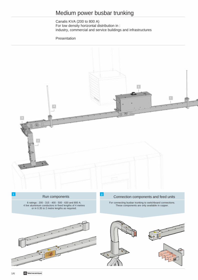
Medium power busbar trunkingCanalis KVA (200 to 800 A)For feeding and connections in :industry, commercial and service buildings and infrastructures
Presentation
Connection components and feed units
For connecting busbar trunking to switchboard connections,generators and transformers. Also for feeding distribution busbar trunking
and for feeding feed trunking from the distribution trunking.These components are only available in copper.
Run components
6 ratings : 200 - 315 - 400 - 500 - 630 and 800 A.4 live aluminium conductors in fixed lengths of 4 metres
or in 0.35 to 2 metre lengths as required.
1 2

1/5Te
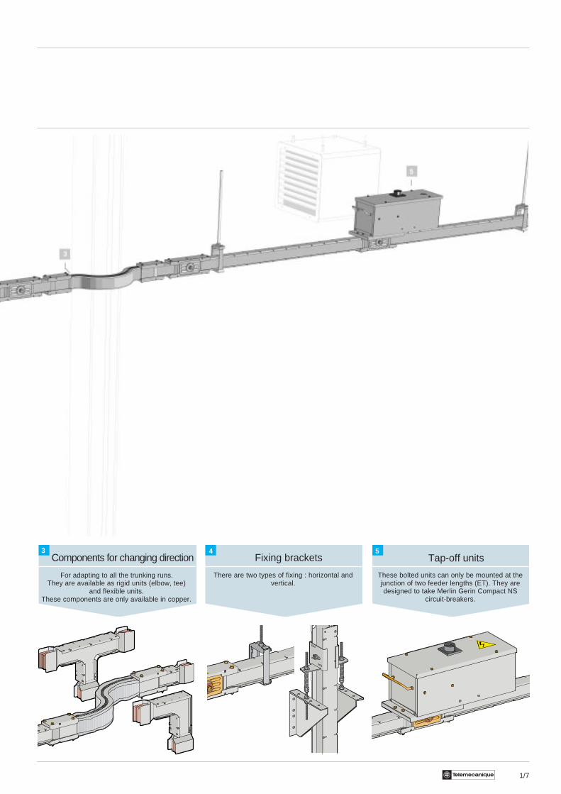
Components for changing direction
For adapting to all the trunking runs.They are available as rigid units (elbow, tee)
or flexible units.These components are only available in copper.
Fixing brackets
There are two types of fixing : horizontal and vertical.
3 4
1/6 Te
Medium power busbar trunkingCanalis KVA (200 to 800 A)For low density horizontal distribution in :industry, commercial and service buildings and infrastructures
Presentation
Connection components and feed unitsRun components
For connecting busbar trunking to switchboard connections.These components are only available in copper.
6 ratings : 200 - 315 - 400 - 500 - 630 and 800 A.4 live aluminium conductors in fixed lengths of 4 metres
or in 0.35 to 2 metre lengths as required.
1 2
1/7Te
Components for changing direction Tap-off unitsFixing brackets
There are two types of fixing : horizontal andvertical.
For adapting to all the trunking runs.They are available as rigid units (elbow, tee)
and flexible units.These components are only available in copper.
These bolted units can only be mounted at thejunction of two feeder lengths (ET). They aredesigned to take Merlin Gerin Compact NS
circuit-breakers.
3 4 5

1/8 Te
Medium power busbar trunkingCanalis KVA (200 to 800 A)For rising main distribution in :service buildings and infrastructures
Presentation
Components for changing direction
Run components
For connecting busbar trunking toswitchboard connections.
These components are only available in copper.
6 ratings : 200 - 315 - 400 - 500 - 630 and 800 A.4 live aluminium conductors in fixed
lengths of 1, 2 or 3 metres or in 2.50 to 4 metrelengths according to the height between floors.
For adapting to all the trunking runs.They are available as rigid units (elbow, tee)
or flexible units.These components are only available in copper.
1
2
3
Connection components and feedunits
1/9Te
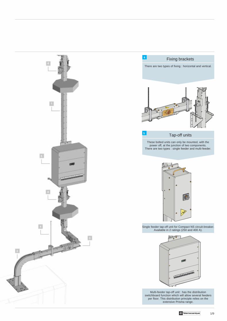
Fixing brackets
There are two types of fixing : horizontal and vertical.
Tap-off units
These bolted units can only be mounted, with thepower off, at the junction of two components.
There are two types : single feeder and multi-feeder.
Single feeder tap-off unit for Compact NS circuit-breaker.Available in 2 ratings (250 and 400 A).
Multi-feeder tap-off unit : has the distributionswitchboard function which will allow several feeders
per floor. This distribution principle relies on theextensive Prisma range.
4
5

Te1/10
Medium power busbar trunkingCanalis KVA (200 to 800 A)
Description
General
Canalis KVA trunking is designed to feed medium power in industrial, commercial or service buildings. It can also be usedto tap off directly from the joint, between two lengths, for rising main distribution or low density distribution applications.This trunking has a compact design, namely with plated conductors inside a metal enclosure. The standard range is IP 52(IP 54 as an option). The isolated conductor bars are made of nickel plated aluminium. The range is divided into 6 ratingsfrom 200 to 800 A. The insulation used on the conductors is halogen-free 130°C class B polyester.
The trunking has :- 4 conductors for the 3-pole + neutral version (cross-section of the neutral equal to the cross-section of thephases). Recommended for TNC scheme.The metal enclosure in prelacquered galvanised sheetsteel (RAL 7032) provides protection and mechanicalresistance for the conductors along their entire length.Moreover, the metal enclosure is used as a protectiveconductor (conforming to NF C15-100) with continuityensured at each junction along the length of the installation.As an option, Canalis KVA can be fitted with an additionalcopper protective conductor (cross-section equal to halfthe cross-section of the phase).Recommended for TNSscheme. With its compact design (no free space within thetrunking), Canalis KVA can be mounted horizontally, edge-wise or vertically without derating the rated current Ith.Moreover, this design does not require the mounting of afire barrier joint to pass through floors and walls. CanalisKVA is designed to be fire-resistant for up to 2 hours.
Run components
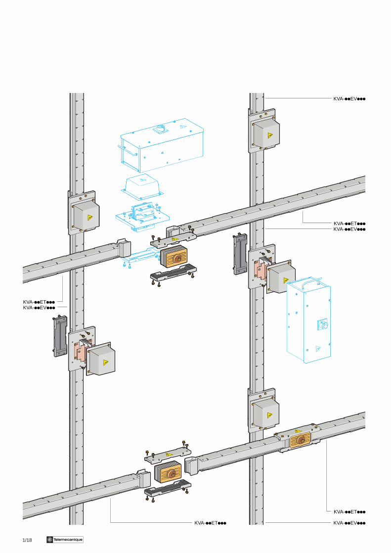
ET TypeThese are designed to feed current through horizontal orvertical runs. A joint between two lengths can be replacedby a special joint which can be used as a tap-off point.These lengths are produced in fixed lengths of 4 metres orin 0.35 m to 2 metre lengths as required.EV TypeThese are designed for rising main distribution. The jointbetween two lengths can be used as a tap-off point. Theselengths are produced in fixed lengths of 1, 2 and 3 metresor in 2.50 m to 4 metre lengths as required.They should be mounted with the neutral on the left.
Junction block
1 This is supplied with the ET run components and thecomponents for changing direction. It provides anelectrical and mechanical joint. When the run has a feedunit at both ends, an additional junction block must beordered.
2 This is supplied with the EV run components. It can beordered separately if ET components are used to replacethe junction block and enable tap-off. It provides anelectrical and mechanical joint as well as a tap-off point.
The electrical junction is ensured by a single junction block(1 to 2 bolts per bar) which provides continuity for all theconductors. The bolt is made up of a screw and a contractionnut, the external head of which breaks when the tighteningtorque is reached. When the head of the nut breaks, a redwasher is released, showing that the electrical junctionoperation has been completed successfully. For disassemblyor maintenance operations, a second head is available.The recommended torque is thus 3 daNm. The junctionblock contacts are silver-plated copper.
Selection :pages 11002/2 and 11002/3Characteristics :pages 11003/2 and 11003/3References :pages 11004/2 to 11004/13Dimensions :pages 11005/2 to 11005/5
1
2

1/11Te
Medium power busbar trunkingCanalis KVA (200 to 800 A)
Description
Connection components and feed units
Connection components can be mounted at either end of the run. If there is a feed unit at both ends of the run, an additionaljunction block should be ordered.
Flange feed unit
The flange feed unit is fitted with a mounting plate (on theswitchboard or transformer cover) and bars. These barsare spread along the axis of the trunking and enable directconnection, by flexible or rigid bars, or by cables, to the lowvoltage terminals of a transformer or the connections of alow voltage switchboard.
Switchboard connection component
The switchboard connection component is fitted with aplate for fixing to the switchboard. Its flexible constructionmeans that it can be connected directly to the connectionsor the protection device, and provides a multidirectionalfeeder at the switchboard outlet.The fixing plate, which runs along the length of the flexiblebar, can be connected directly to the protection deviceinside the switchboard, wherever it is situated.
Warning : for connection by braid, a fixer must be providedevery 300 mm (maximum value) inside the switchboard. Todo this, use the Prisma P cable tray.
KH - KV connector
The KH - KV connector supplies a feed run directly from aKH high power distribution tap-off unit. Its flexible designaccommodates any changes in alignment, level and axis.It is fitted at one end with an SB or SD tap-off unit outletplate from the KH range with flexible braids for connectionto the protection device and, at the other end, with a KVconnector end.
Selection :pages 11002/2 and 11002/3Characteristics :pages 11003/2 and 11003/3References :pages 11004/2 to 11004/13Dimensions :pages 11005/2 to 11005/5
1/12 Te
Medium power busbar trunkingCanalis KVA (200 to 800 A)
Description
Connection components and feed units (continued)
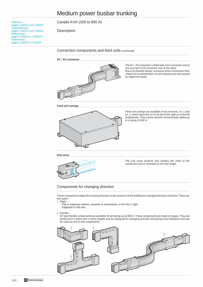
KV - KS connector
The KV - KS connector is fitted with a KV connector end atone end and a KS connector end at the other.Due to its flexible design, it ensures direct connection froma feed run to a distribution run and reduces any risk causedby alignment faults.
Feed unit casings
Feed unit casings are available in two versions, no. 1 andno. 2, which allow the run to be fed to the right or to the leftrespectively. They can be used for connecting by cables upto a rating of 800 A.
End cover
The end cover protects and isolates the ends of theconductors and is mounted on the last length.
Components for changing direction
These components adapt the trunking direction to the contours of the building by changing direction and level. There aretwo types :1 Rigid :
- Flat or edgewise elbows, upwards or downwards, to the left or right- Edgewise or flat tees
2 Flexible :EF type flexible components are available for all ratings up to 800 A. These components are made of copper. They areproduced in 2 metre and 1 metre lengths and are designed for changing direction and going round obstacles and canbe used as end of site components.
Selection :pages 11002/2 and 11002/3Characteristics :pages 11003/2 and 11003/3References :pages 11004/2 to 11004/13Dimensions :pages 11005/2 to 11005/5
2
1
1
1
1/13Te
Medium power busbar trunkingCanalis KVA (200 to 800 A)
Description
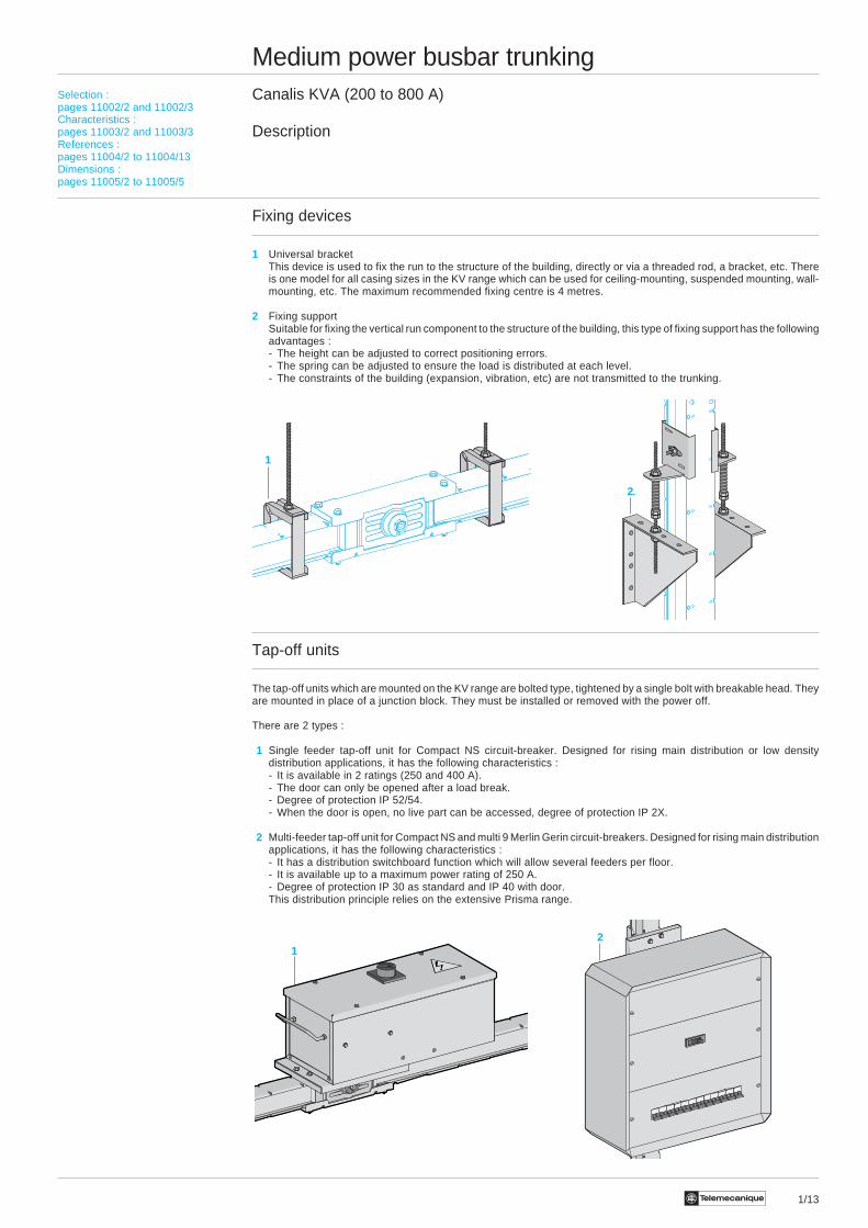
Fixing devices
1 Universal bracketThis device is used to fix the run to the structure of the building, directly or via a threaded rod, a bracket, etc. Thereis one model for all casing sizes in the KV range which can be used for ceiling-mounting, suspended mounting, wall-mounting, etc. The maximum recommended fixing centre is 4 metres.
2 Fixing supportSuitable for fixing the vertical run component to the structure of the building, this type of fixing support has the followingadvantages :- The height can be adjusted to correct positioning errors.- The spring can be adjusted to ensure the load is distributed at each level.- The constraints of the building (expansion, vibration, etc) are not transmitted to the trunking.
Tap-off units
The tap-off units which are mounted on the KV range are bolted type, tightened by a single bolt with breakable head. Theyare mounted in place of a junction block. They must be installed or removed with the power off.
There are 2 types :
1 Single feeder tap-off unit for Compact NS circuit-breaker. Designed for rising main distribution or low densitydistribution applications, it has the following characteristics :- It is available in 2 ratings (250 and 400 A).- The door can only be opened after a load break.- Degree of protection IP 52/54.- When the door is open, no live part can be accessed, degree of protection IP 2X.
2 Multi-feeder tap-off unit for Compact NS and multi 9 Merlin Gerin circuit-breakers. Designed for rising main distributionapplications, it has the following characteristics :- It has a distribution switchboard function which will allow several feeders per floor.- It is available up to a maximum power rating of 250 A.- Degree of protection IP 30 as standard and IP 40 with door.This distribution principle relies on the extensive Prisma range.
2
Selection :pages 11002/2 and 11002/3Characteristics :pages 11003/2 and 11003/3References :pages 11004/2 to 11004/13Dimensions :pages 11005/2 to 11005/5
21
1

1/14 Te
Medium power busbar trunkingCanalis KVA (200 to 800 A)
Selection guide
Determining the rating according to the temperature rise
The rating of a busbar trunking, in amps, represents the maximum intensity of the constant current which the trunking cancontinuously support, for an average ambient temperature of 35 °C, and in accordance with standard temperature rises(IEC 439.2).
Determining the rating according to the temperature rise consists of selecting the busbar trunking rating immediatelyabove the operating current of the installation. However, as a rule, the intensity of the current which crosses a busbartrunking is constantly fluctuating. The operating current is therefore defined as that of the constant current which producesthe same thermal effects as the actual current.
It is sometimes difficult to determine the operating current, especially when there is no reading for the installation or foran equivalent installation. The operating current can be estimated with sufficient precision by calculating the product ofthe nominal currents of receivers connected to the busbar trunking by a coefficient known as the “average demandcoefficient”. The average demand coefficient is empirically determined by comparison with existing installations. It isdependent upon :- the average quantity of receivers operating- the load variation of each receiver (a receiver rarely absorbs its maximum power, as peak periods alternate with those
of no-load operation)- whether several receivers are operating at the same time, whether peaks are superimposed and the duration of these
peaks
As an example, here are a few coefficients for a general mechanical engineering workshop.
Number of receivers Average demand coefficient
2 or 3 0.9
4 or 5 0.8
6 to 9 0.7
10 to 40 0.6
40 plus 0.5
Depending on the ambient temperature, the trunking must be derated (see characteristics pages 11003/2 and 11003/3).
Checking the rating according to the permissible voltage drop
The permissible voltage drop is that which is compatible with the correct operation of receivers (refer to the manufacturers'manuals).
i Read the voltage drop in mV/m/A in the tables on page 11003/3 for the busbar trunking selected according to thetemperature rise.
i Determine the voltage drop for the most disadvantaged receivers, namely those which are the furthest from the sourceand for the highest current. If the voltage drop is not permissible, select the rating immediately above.
i Repeat the checking procedure for the new rating.
Checking the rating according to withstand to short-circuit currents
i Calculate the intensity of the short-circuit current at the points which are considered to be unfavourable.
i Check, by referring to the tables on pages 11003/2 and 11003/3, that the selected rating of the trunking enables it towithstand this short-circuit current. If this is not the case, there are two possible solutions :- Select trunking of a higher rating and repeat the checking procedure.- Provide a protection system which limits current peaks upstream of the trunking.
Description :pages 11001/2 to 11001/5Characteristics :pages 11003/2 and 11003/3References :pages 11004/2 to 11004/13Dimensions :pages 11005/2 to 11005/5
1/15Te
Description :pages 11001/2 to 11001/5Characteristics :pages 11003/2 and 11003/3References :pages 11004/2 to 11004/13Dimensions :pages 11005/2 to 11005/5
Medium power busbar trunkingCanalis KVA (200 to 800 A)
Selection guide
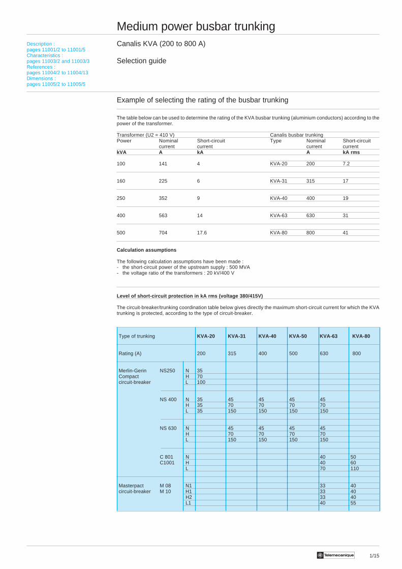
Example of selecting the rating of the busbar trunking
The table below can be used to determine the rating of the KVA busbar trunking (aluminium conductors) according to thepower of the transformer.
Transformer (U2 = 410 V) Canalis busbar trunkingPower Nominal Short-circuit Type Nominal Short-circuit
current current current currentkVA A kA A kA rms
100 141 4 KVA-20 200 7.2
160 225 6 KVA-31 315 17
250 352 9 KVA-40 400 19
400 563 14 KVA-63 630 31
500 704 17.6 KVA-80 800 41
Calculation assumptions
The following calculation assumptions have been made :- the short-circuit power of the upstream supply : 500 MVA- the voltage ratio of the transformers : 20 kV/400 V
Level of short-circuit protection in kA rms (voltage 380/415V)
The circuit-breaker/trunking coordination table below gives directly the maximum short-circuit current for which the KVAtrunking is protected, according to the type of circuit-breaker.
Type of trunking KVA-20 KVA-31 KVA-40 KVA-50 KVA-63 KVA-80
Rating (A) 200 315 400 500 630 800
Merlin-Gerin NS250 N 35Compact H 70circuit-breaker L 100
NS 400 N 35 45 45 45 45H 35 70 70 70 70L 35 150 150 150 150
NS 630 N 45 45 45 45H 70 70 70 70L 150 150 150 150
C 801 N 40 50C1001 H 40 60
L 70 110
Masterpact M 08 N1 33 40circuit-breaker M 10 H1 33 40
H2 33 40L1 40 55
1/16 Te
Description :pages 11001/2 to 11001/5Selection guide :pages 11002/2 and 11002/3References :pages 11004/2 to 11004/13Dimensions :pages 11005/2 to 11005/5
Medium power busbar trunkingCanalis KVA (200 to 800 A)
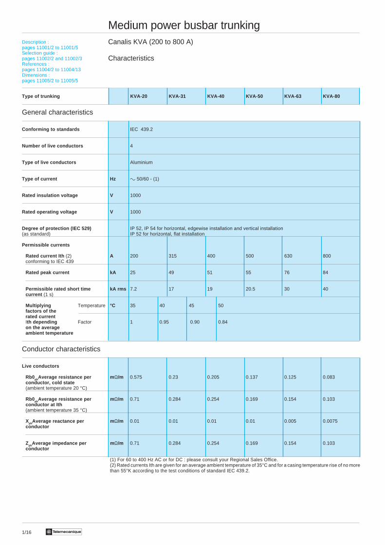
Characteristics
Type of trunking KVA-20 KVA-31 KVA-40 KVA-50 KVA-63 KVA-80
General characteristics
Conforming to standards IEC 439.2
Number of live conductors 4
Type of live conductors Aluminium
Type of current Hz c 50/60 - (1)
Rated insulation voltage V 1000
Rated operating voltage V 1000
Degree of protection (IEC 529) IP 52, IP 54 for horizontal, edgewise installation and vertical installation(as standard) IP 52 for horizontal, flat installation
Permissible currents
Rated current Ith (2) A 200 315 400 500 630 800conforming to IEC 439
Rated peak current kA 25 49 51 55 76 84
Permissible rated short time kA rms 7.2 17 19 20.5 30 40current (1 s)
Multiplying Temperature °C 35 40 45 50factors of therated currentIth depending Factor 1 0.95 0.90 0.84on the averageambient temperature
Conductor characteristics
Live conductors
Rb0phAverage resistance per m Ω/m 0.575 0.23 0.205 0.137 0.125 0.083conductor, cold state(ambient temperature 20 °C)
Rb0phAverage resistance per m Ω/m 0.71 0.284 0.254 0.169 0.154 0.103conductor at Ith(ambient temperature 35 °C)
XphAverage reactance per m Ω/m 0.01 0.01 0.01 0.01 0.005 0.0075conductor
ZphAverage impedance per m Ω/m 0.71 0.284 0.254 0.169 0.154 0.103conductor
(1) For 60 to 400 Hz AC or for DC : please consult your Regional Sales Office.(2) Rated currents Ith are given for an average ambient temperature of 35°C and for a casing temperature rise of no morethan 55°K according to the test conditions of standard IEC 439.2.

1/17Te
Description :pages 11001/2 to 11001/5Selection guide :pages 11002/2 and 11002/3References :pages 11004/2 to 11004/13Dimensions :pages 11005/2 to 11005/5
Medium power busbar trunkingCanalis KVA (200 to 800 A)
Characteristics
Type of trunking KVA-20 KVA-31 KVA-40 KVA-50 KVA-63 KVA-80
Other characteristics
Live conductors
Rb1ph ph or phN Average resistance m Ω/m 1.42 0.568 0.508 0.338 0.308 0.206of fault loops betweenlive conductors
Rb2ph ph or phN Average resistance m Ω/m 1.704 0.682 0.609 0.406 0.37 0.247of fault loops betweenlive conductors
Rb1ph PE Average resistance m Ω/m 1.374 0.948 0.793 0.708 0.482 0.431of fault loops betweenlive conductors and PE
Xb1ph ph or phN Average reactance m Ω/m 0.02 0.02 0.02 0.02 0.01 0.015of fault loops betweenlive conductors
Xb1ph PE Average reactance m Ω/m 0.02 0.02 0.02 0.02 0.01 0.015of fault loops betweenlive conductors and PE
Voltage drop Composite voltage drop, hot state, in millivolts per metre and per amp, for three-phase 50 Hz current, with loadconcentrated at the end of the run (feed run). If the load is distributed along the run, voltage drops are half the valuesindicated in the table below.
For a power factor ϕ mV/m/A 0.872 0.356 0.32 0.218 0.192 0.134of 0.7
For a power factor ϕ mV/m/A 0.994 0.404 0.362 0.244 0.218 0.15of 0.8
For a power factor ϕ mV/m/A 1.114 0.45 0.404 0.27 0.244 0.166of 0.9
For a power factor ϕ mV/m/A 1.23 0.492 0.44 0.292 0.266 0.178of 1
Protective conductor
Casing Equivalent mm 2 26 26 32 32 42 42coppercross-section
Average resistance, mΩ/m 0.664 0.664 0.539 0.539 0.328 0.328cold state (ambienttemperature 20°C)
Additional Equivalent mm 2 40 40 102 102 165 165conductor copper
cross-section
Average resistance, mΩ/m 0.298 0.298 0.145 0.145 0.11 0.11cold state (ambienttemperature 20°C)
Average weight3L + N + PE kg/m 2.7 3.8 4.5 6.1 7.6 10.8
3L + N + PER kg/m 3 4.3 5.3 6.8 8.6 11.8
1/18 Te
KVA-iiEViii
KVA-iiETiiiKVA-iiEViii
KVA-iiETiii
KVA-iiEViiiKVA-iiETiii
KVA-iiETiiiKVA-iiEViii
1/19Te
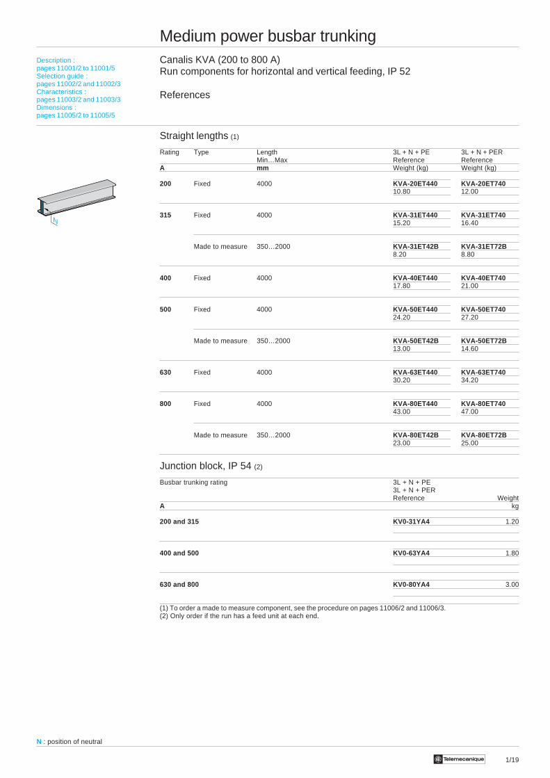
Medium power busbar trunkingCanalis KVA (200 to 800 A)Run components for horizontal and vertical feeding, IP 52
References
Straight lengths (1)
Rating Type Length 3L + N + PE 3L + N + PERMin…Max Reference Reference
A mm Weight (kg) Weight (kg)
200 Fixed 4000 KVA-20ET440 KVA-20ET74010.80 12.00
315 Fixed 4000 KVA-31ET440 KVA-31ET74015.20 16.40
Made to measure 350…2000 KVA-31ET42B KVA-31ET72B8.20 8.80
400 Fixed 4000 KVA-40ET440 KVA-40ET74017.80 21.00
500 Fixed 4000 KVA-50ET440 KVA-50ET74024.20 27.20
Made to measure 350…2000 KVA-50ET42B KVA-50ET72B13.00 14.60
630 Fixed 4000 KVA-63ET440 KVA-63ET74030.20 34.20
800 Fixed 4000 KVA-80ET440 KVA-80ET74043.00 47.00
Made to measure 350…2000 KVA-80ET42B KVA-80ET72B23.00 25.00
Junction block, IP 54 (2)
Busbar trunking rating 3L + N + PE3L + N + PERReference Weight
A kg
200 and 315 KV0-31YA4 1.20
400 and 500 KV0-63YA4 1.80
630 and 800 KV0-80YA4 3.00
(1) To order a made to measure component, see the procedure on pages 11006/2 and 11006/3.(2) Only order if the run has a feed unit at each end.
N
Description :pages 11001/2 to 11001/5Selection guide :pages 11002/2 and 11002/3Characteristics :pages 11003/2 and 11003/3Dimensions :pages 11005/2 to 11005/5
N : position of neutral
Te1/20
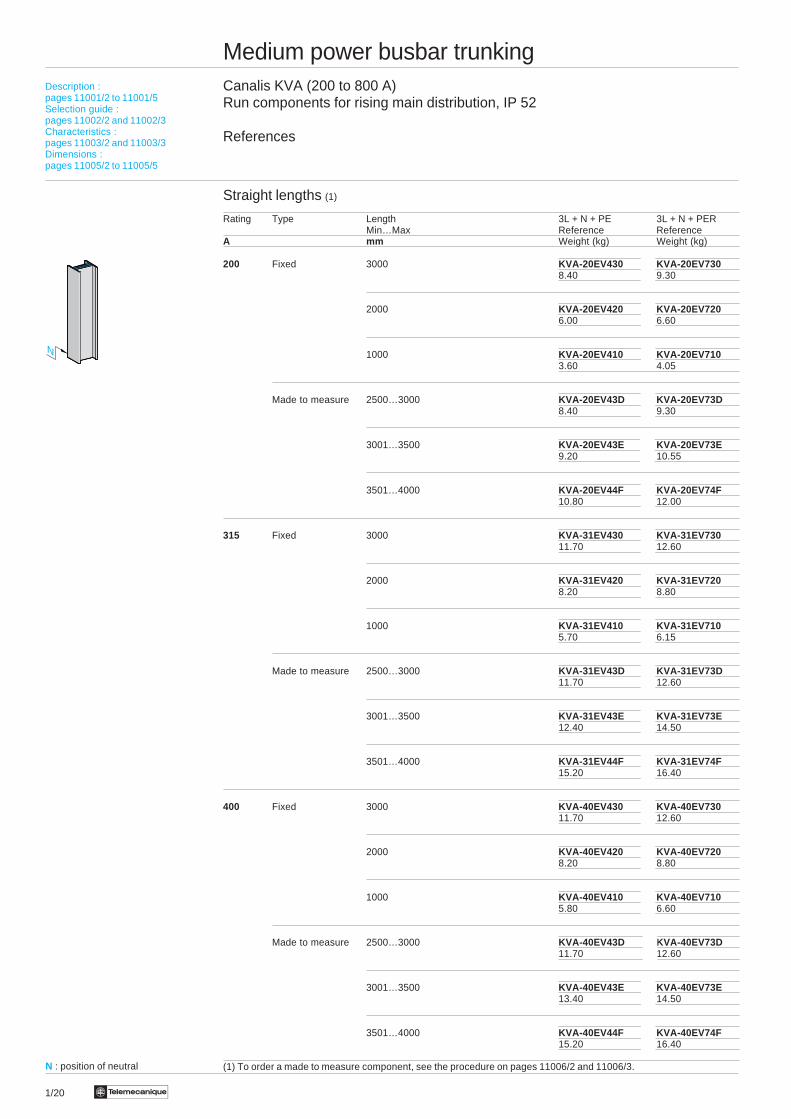
Medium power busbar trunkingCanalis KVA (200 to 800 A)Run components for rising main distribution, IP 52
References
Straight lengths (1)
Rating Type Length 3L + N + PE 3L + N + PERMin…Max Reference Reference
A mm Weight (kg) Weight (kg)
200 Fixed 3000 KVA-20EV430 KVA-20EV7308.40 9.30
2000 KVA-20EV420 KVA-20EV7206.00 6.60
1000 KVA-20EV410 KVA-20EV7103.60 4.05
Made to measure 2500…3000 KVA-20EV43D KVA-20EV73D8.40 9.30
3001…3500 KVA-20EV43E KVA-20EV73E9.20 10.55
3501…4000 KVA-20EV44F KVA-20EV74F10.80 12.00
315 Fixed 3000 KVA-31EV430 KVA-31EV73011.70 12.60
2000 KVA-31EV420 KVA-31EV7208.20 8.80
1000 KVA-31EV410 KVA-31EV7105.70 6.15
Made to measure 2500…3000 KVA-31EV43D KVA-31EV73D11.70 12.60
3001…3500 KVA-31EV43E KVA-31EV73E12.40 14.50
3501…4000 KVA-31EV44F KVA-31EV74F15.20 16.40
400 Fixed 3000 KVA-40EV430 KVA-40EV73011.70 12.60
2000 KVA-40EV420 KVA-40EV7208.20 8.80
1000 KVA-40EV410 KVA-40EV7105.80 6.60
Made to measure 2500…3000 KVA-40EV43D KVA-40EV73D11.70 12.60
3001…3500 KVA-40EV43E KVA-40EV73E13.40 14.50
3501…4000 KVA-40EV44F KVA-40EV74F15.20 16.40
(1) To order a made to measure component, see the procedure on pages 11006/2 and 11006/3.
Description :pages 11001/2 to 11001/5Selection guide :pages 11002/2 and 11002/3Characteristics :pages 11003/2 and 11003/3Dimensions :pages 11005/2 to 11005/5
N : position of neutral
N
Te 1/21
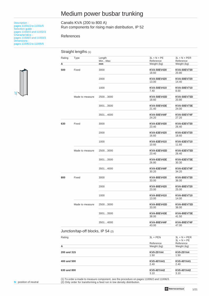
Medium power busbar trunkingCanalis KVA (200 to 800 A)Run components for rising main distribution, IP 52
References
Straight lengths (1)
Rating Type Length 3L + N + PE 3L + N + PERMin…Max Reference Reference
A mm Weight (kg) Weight (kg)
500 Fixed 3000 KVA-50EV430 KVA-50EV73018.60 20.80
2000 KVA-50EV420 KVA-50EV72013.00 14.40
1000 KVA-50EV410 KVA-50EV7107.40 8.00
Made to measure 2500…3000 KVA-50EV43D KVA-50EV73D18.60 20.80
3001…3500 KVA-50EV43E KVA-50EV73E21.40 24.00
3501…4000 KVA-50EV44F KVA-50EV74F24.20 27.20
630 Fixed 3000 KVA-63EV430 KVA-63EV73023.40 26.40
2000 KVA-63EV420 KVA-63EV72016.60 18.60
1000 KVA-63EV410 KVA-63EV71010.60 11.60
Made to measure 2500…3000 KVA-63EV43D KVA-63EV73D23.40 26.40
3001…3500 KVA-63EV43E KVA-63EV73E26.80 30.30
3501…4000 KVA-63EV44F KVA-63EV74F30.20 34.20
800 Fixed 3000 KVA-80EV430 KVA-80EV73033.00 36.00
2000 KVA-80EV420 KVA-80EV72023.00 25.00
1000 KVA-80EV410 KVA-80EV71013.00 14.00
Made to measure 2500…3000 KVA-80EV43D KVA-80EV73D33.00 36.00
3001…3500 KVA-80EV43E KVA-80EV73E38.00 41.50
3501…4000 KVA-80EV44F KVA-80EV74F43.00 47.00
Junction/tap-off blocks, IP 54 (2)
Rating 3L + PEN 3L + N + PER3L + N + PE
Reference ReferenceA Weight (kg) Weight (kg)
200 and 315 KV0-25YA4 KV0-25YA41.50 1.50
400 and 500 KV0-40YA41 KV0-40YA412.40 2.40
630 and 800 KV0-40YA42 KV0-40YA423.10 3.10
(1) To order a made to measure component, see the procedure on pages 11006/2 and 11006/3.(2) Only order for transforming a feed run in low density distribution.
Description :pages 11001/2 to 11001/5Selection guide :pages 11002/2 and 11002/3Characteristics :pages 11003/2 and 11003/3Dimensions :pages 11005/2 to 11005/5
N : position of neutral
N
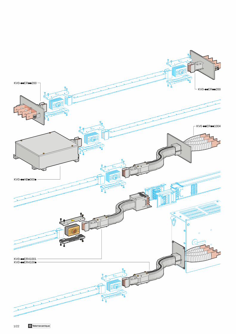
1/22 Te
KV0-iiERii200
KV0-iiERii1004
KV0-iiER41001KV0-iiER4100i
KV0-iiABi000i
KV0-iiERii200

1/23Te
Medium power busbar trunkingCanalis KVA (200 to 800 A)Connection components and feed units, IP 52End covers
References
Feed units
End feed boxRating Lengths 3L + N + PE 3L + N + PER
a, e Reference ReferenceA mm Weight (kg) Weight (kg)
200 and 315 150 KV0-31ER40200 KV0-31ER702002.70 2.90
400 and 500 150 KV0-63ER40200 KV0-63ER702005.10 5.50
630 and 800 150 KV0-80ER40200 KV0-80ER7020010.00 10.50
N1 feed unit with connection via cable
200 and 315 – KV0-31AB40001 KV0-31AB700013.80 4.00
400 and 500 – KV0-63AB40001 KV0-63AB700017.20 7.70
630 and 800 – KV0-80AB40001 KV0-80AB7000114.00 14.70
N2 feed unit with connection via cable
200 and 315 – KV0-31AB40002 KV0-31AB700023.80 4.00
400 and 500 – KV0-63AB40002 KV0-63AB700027.20 7.70
630 and 800 – KV0-80AB40002 KV0-80AB7000214.00 14.70
Switchboard connection component
Rating 3L + N + PE3L + N + PERReference Weight
A kg
315 KV0-31ER71004 12.60
630 KV0-63ER71004 23.80
800 KV0-80ER71004 55.00
KV - KS connector (3L + N + PE)
KV = 315/KS = 250 KV = 500/KS = 500 KV = 800/KS = 800
KV0-25ER41001 KV0-50ER41001 KV0-80ER4100112.60 23.80 43.00
KH - KV connector (3L + N + PE)
KV = 315 KV = 315 KV = 500 KV = 800KH SB400 unit KH SD400 unit KH SB1000 unit KH SB1000 unit
KV0-25ER41002 KV0-50ER41003 KV0-63ER41002 KV0-80ER4100212.60 12.60 23.80 43.00
End cover IP 54 (3L + N + PE ou 3L + N + PER)
Busbar trunking rating Reference MasseA kg
200 and 315 KV0-31FA 1.00
400 and 500 KV0-63FA 1.10
630 and 800 KV0-80FA 1.20
Description :pages 11001/2 to 11001/5Selection guide :pages 11002/2 and 11002/3Characteristics :pages 11003/2 and 11003/3Dimensions :pages 11005/2 to 11005/5
N
a
ee
e
N
N2
N1
N
N
Ni : position of neutral
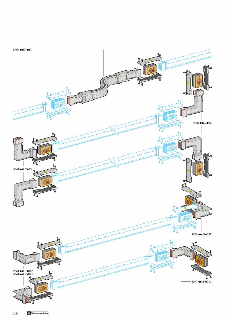
1/24 Te
KV0-iiEFii0
KV0-iiLCi05
KV0-iiLCi05
KV0-iiLPi042
KV0-iiLPi042KV0-iiLPi041
KV0-iiLPi041
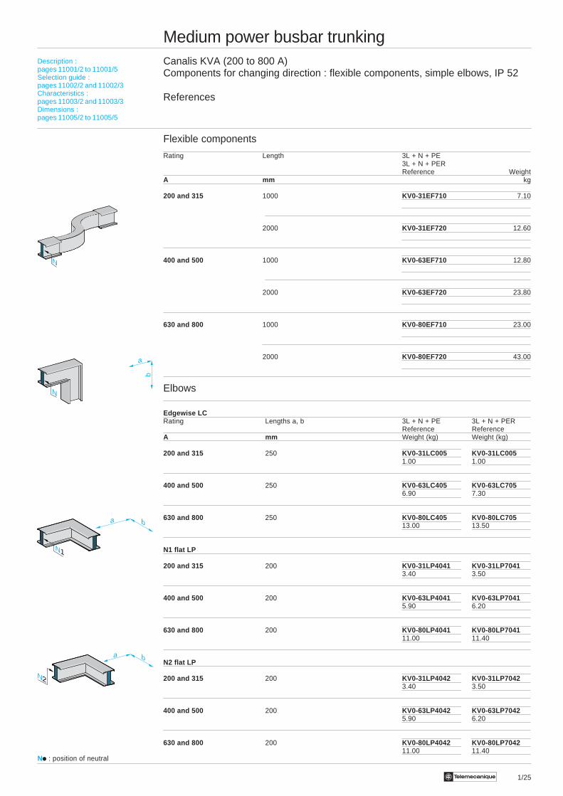
1/25Te
Medium power busbar trunkingCanalis KVA (200 to 800 A)Components for changing direction : flexible components, simple elbows, IP 52
References
Flexible components
Rating Length 3L + N + PE3L + N + PERReference Weight
A mm kg
200 and 315 1000 KV0-31EF710 7.10
2000 KV0-31EF720 12.60
400 and 500 1000 KV0-63EF710 12.80
2000 KV0-63EF720 23.80
630 and 800 1000 KV0-80EF710 23.00
2000 KV0-80EF720 43.00
Elbows
Edgewise LCRating Lengths a, b 3L + N + PE 3L + N + PER
Reference ReferenceA mm Weight (kg) Weight (kg)
200 and 315 250 KV0-31LC005 KV0-31LC0051.00 1.00
400 and 500 250 KV0-63LC405 KV0-63LC7056.90 7.30
630 and 800 250 KV0-80LC405 KV0-80LC70513.00 13.50
N1 flat LP
200 and 315 200 KV0-31LP4041 KV0-31LP70413.40 3.50
400 and 500 200 KV0-63LP4041 KV0-63LP70415.90 6.20
630 and 800 200 KV0-80LP4041 KV0-80LP704111.00 11.40
N2 flat LP
200 and 315 200 KV0-31LP4042 KV0-31LP70423.40 3.50
400 and 500 200 KV0-63LP4042 KV0-63LP70425.90 6.20
630 and 800 200 KV0-80LP4042 KV0-80LP704211.00 11.40
a b
a b
N1
N
a
b
N
N2
Description :pages 11001/2 to 11001/5Selection guide :pages 11002/2 and 11002/3Characteristics :pages 11003/2 and 11003/3Dimensions :pages 11005/2 to 11005/5
Ni : position of neutral

1/27Te
Medium power busbar trunkingCanalis KVA (200 to 800 A)Component for changing direction : Tees, IP 52Fixing devices
References
Tees, IP 52
Edgewise TCRating Lengths a. b. c 3L + N + PE 3L + N + PER
Reference ReferenceA mm Weight (kg) Weight (kg)
200 and 315 250 KV0-31TC407 KV0-31TC7075.30 5.50
400 and 500 250 KV0-63TC407 KV0-63TC7079.50 10.10
630 and 800 250 KV0-80TC407 KV0-80TC70718.00 18.80
N1 flat TP
200 and 315 300 KV0-31TP4091 KV0-31TP70916.10 6.40
400 and 500 300 KV0-63TP4091 KV0-63TP709111.00 11.70
630 and 800 300 KV0-80TP4091 KV0-80TP709121.00 21.90
N2 flat TP
200 and 315 300 KV0-31TP4092 KV0-31TP70926.10 6.40
400 and 500 300 KV0-63TP4092 KV0-63TP709211.00 11.70
630 and 800 300 KV0-80TP4092 KV0-80TP709221.00 21.90
Fixing Devices
Description Rating Reference WeightA kg
Horizontal fixing bracket 200...800 KV0-80ZA1 0.50
Vertical fixing for 200 and 315 KV0-31ZA2 1.00rising main distribution
400 and 500 KV0-63ZA2 1.00
630 and 800 KV0-80ZA2 1.00
ac
b
N
bac
N1
N2
bac
Description :pages 11001/2 to 11001/5Selection guide :pages 11002/2 and 11002/3Characteristics :pages 11003/2 and 11003/3Dimensions :pages 11005/2 to 11005/5
Ni : position of neutral
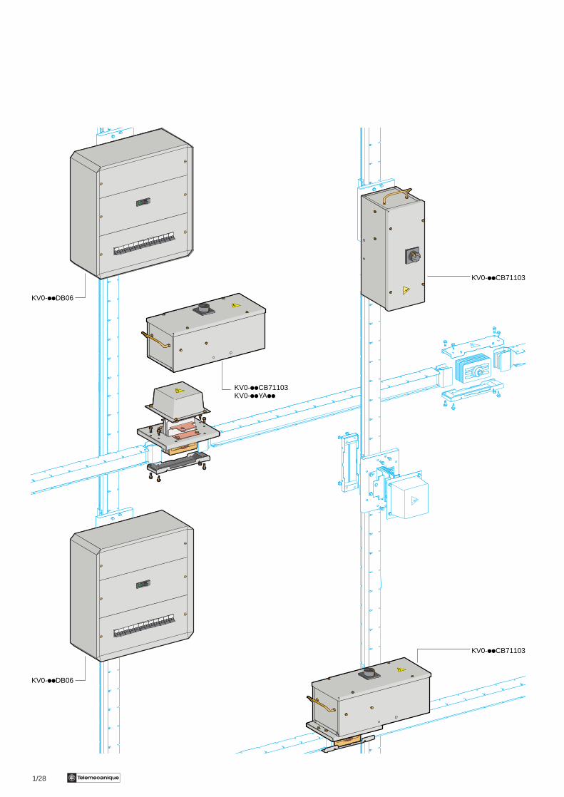
1/28 Te
KV0-iiCB71103KV0-iiYAii
KV0-iiCB71103
KV0-iiCB71103
KV0-iiDB06
KV0-iiDB06
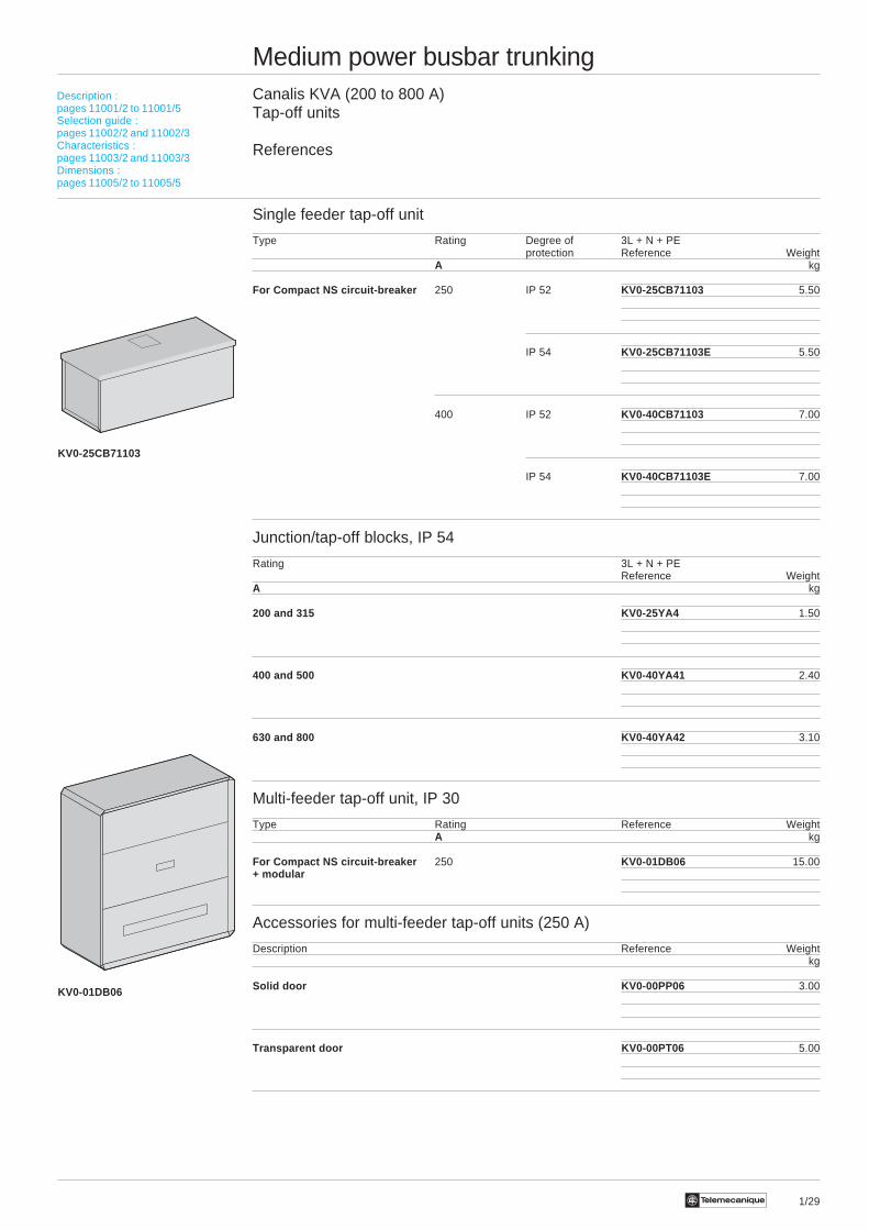
1/29Te
Medium power busbar trunkingCanalis KVA (200 to 800 A)Tap-off units
References
Single feeder tap-off unit
Type Rating Degree of 3L + N + PEprotection Reference Weight
A kg
For Compact NS circuit-breaker 250 IP 52 KV0-25CB71103 5.50
IP 54 KV0-25CB71103E 5.50
400 IP 52 KV0-40CB71103 7.00
IP 54 KV0-40CB71103E 7.00
Junction/tap-off blocks, IP 54
Rating 3L + N + PEReference Weight
A kg
200 and 315 KV0-25YA4 1.50
400 and 500 KV0-40YA41 2.40
630 and 800 KV0-40YA42 3.10
Multi-feeder tap-off unit, IP 30
Type Rating Reference WeightA kg
For Compact NS circuit-breaker 250 KV0-01DB06 15.00+ modular
Accessories for multi-feeder tap-off units (250 A)
Description Reference Weightkg
Solid door KV0-00PP06 3.00
Transparent door KV0-00PT06 5.00
Description :pages 11001/2 to 11001/5Selection guide :pages 11002/2 and 11002/3Characteristics :pages 11003/2 and 11003/3Dimensions :pages 11005/2 to 11005/5
KV0-25CB71103
KV0-01DB06
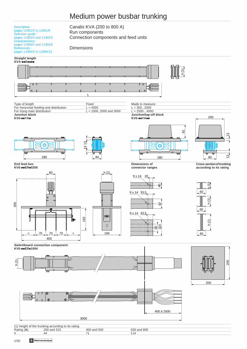
1/30 Te
Medium power busbar trunkingCanalis KVA (200 to 800 A)Run componentsConnection components and feed units
Dimensions
Straight lengthKVA-iiEiiii
Type of length Fixed Made to measureFor horizontal feeding and distribution L = 4000 L = 350...2000For rising main distribution L = 1000, 2000 and 3000 L = 2500…4000Junction block Junction/tap-off blockKV0-iiYAi KV0-iiYAii
End feed box Dimensions of Cross-section of trunkingKV0-iiERi0200 connector ranges according to its rating
Switchboard connection componentKV0-iiERi1004
(1) Height of the trunking according to its ratingRating (A) 200 and 315 400 and 500 630 and 800h 44 71 114
Description :pages 11001/2 to 11001/5Selection guide :pages 11002/2 and 11002/3Characteristics :pages 11003/2 and 11003/3References :pages 11004/2 to 11004/13
L
h (1
)
h (1
)60
h (1
)
60
h (1
)
60
40
209 x 14
67
33,59 x 14
50 110
33,59 x 14
3000
200
200
h (1
)
400 à 2500
90
200
1313
280
92
h (1)
190
60
= =70 70
400
70
150
350
84
1313
280
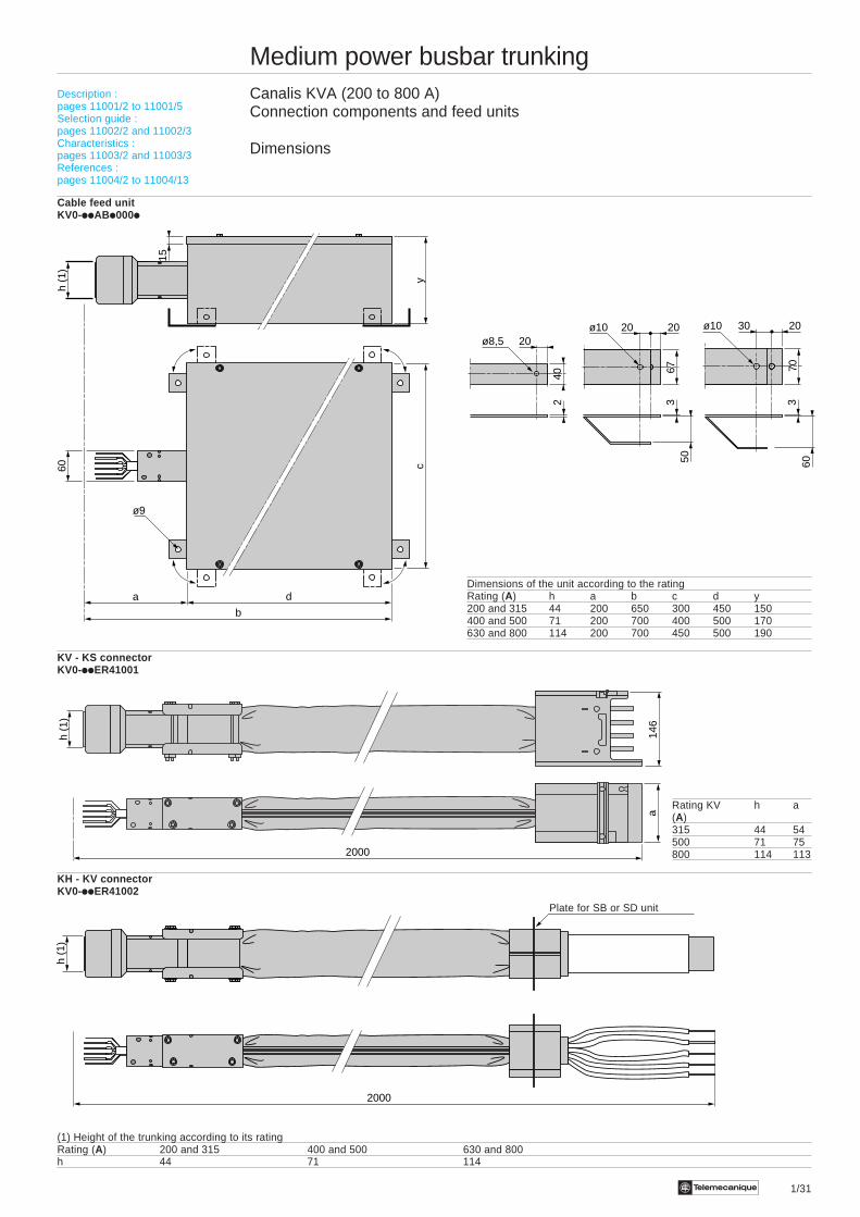
Te 1/31
Medium power busbar trunkingCanalis KVA (200 to 800 A)Connection components and feed units
Dimensions
Cable feed unitKV0-iiABi000i
Dimensions of the unit according to the ratingRating (A) h a b c d y200 and 315 44 200 650 300 450 150400 and 500 71 200 700 400 500 170630 and 800 114 200 700 450 500 190
KV - KS connectorKV0-iiER41001
Rating KV h a(A)315 44 54500 71 75800 114 113
KH - KV connectorKV0-iiER41002
(1) Height of the trunking according to its ratingRating (A) 200 and 315 400 and 500 630 and 800h 44 71 114
Description :pages 11001/2 to 11001/5Selection guide :pages 11002/2 and 11002/3Characteristics :pages 11003/2 and 11003/3References :pages 11004/2 to 11004/13
146
2000
a
h (1
)
240
20ø8,5
6750
20 20ø10
6070
30 20ø10
3 3
2000
h (1
)
Plate for SB or SD unit
b
da
h (1
)60
yc
15
ø9
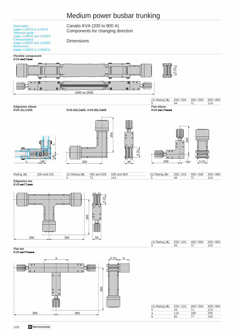
1/32 Te
Medium power busbar trunkingCanalis KVA (200 to 800 A)Components for changing direction
Dimensions
Flexible componentKV0-iiEFiii
(1) Rating (A) 200 / 315 400 / 500 630 / 800h 44 71 114
Edgewise elbow Flat elbowKV0-31LC005 KV0-63LC i05, KV0-80LCi05 KV0-iiLPiiii
Rating (A) 200 and 315 (1) Rating (A) 400 and 500 630 and 800 (1) Rating (A) 200 / 315 400 / 500 630 / 800h 71 114 h 44 71 114
Edgewise teeKV0-iiTCiii
(1) Rating (A) 200 / 315 400 / 500 630 / 800h 44 71 114
Flat teeKV0-iiTPiiii
(1) Rating (A) 200 / 315 400 / 500 630 / 800h 44 71 114a 115 169 255b 50 77 120
Description :pages 11001/2 to 11001/5Selection guide :pages 11002/2 and 11002/3Characteristics :pages 11003/2 and 11003/3References :pages 11004/2 to 11004/13
a h (1) b
300300
300
250 250
250
60
h (1
)
1000 ou 2000
h (1
)
250
250
h (1
)
60 h (1)200
200
90°L 40
L40
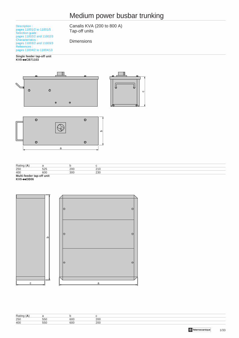
Te 1/33
Medium power busbar trunkingCanalis KVA (200 to 800 A)Tap-off units
Dimensions
Single feeder tap-off unitKV0-iiCB71103
Rating (A) a b c250 525 200 210400 600 300 230Multi-feeder tap-off unitKV0-iiDB06
Rating (A) a b c250 550 600 200400 550 600 200
Description :pages 11001/2 to 11001/5Selection guide :pages 11002/2 and 11002/3Characteristics :pages 11003/2 and 11003/3References :pages 11004/2 to 11004/13
b
a
c
c
b
a
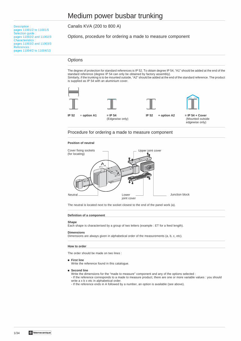
1/34 Te
Medium power busbar trunkingCanalis KVA (200 to 800 A)
Options, procedure for ordering a made to measure component
Options
The degree of protection for standard references is IP 52. To obtain degree IP 54, “A1” should be added at the end of thestandard reference (degree IP 54 can only be obtained by factory assembly).Similarly, if the trunking is to be mounted outside, “A2” should be added at the end of the standard reference. The productis supplied as IP 54 with an aluminium cover.
IP 52 + option A1 = IP 54 IP 52 + option A2 = IP 54 + Cover(Edgewise only) (Mounted outside
edgewise only)
Procedure for ordering a made to measure component
Position of neutral
The neutral is located next to the socket closest to the end of the panel work (a).
Definition of a component
ShapeEach shape is characterised by a group of two letters (example : ET for a feed length).
DimensionsDimensions are always given in alphabetical order of the measurements (a, b, c, etc).
How to order
The order should be made on two lines :
i First lineWrite the reference found in this catalogue.
i Second lineWrite the dimensions for the “made to measure” component and any of the options selected :- If the reference corresponds to a made to measure product, there are one or more variable values : you shouldwrite a x b x etc in alphabetical order.- If the reference ends in A followed by a number, an option is available (see above).
Description :pages 11001/2 to 11001/5Selection guide :pages 11002/2 and 11002/3Characteristics :pages 11003/2 and 11003/3References :pages 11004/2 to 11004/13
Upper joint cover
Junction blockNeutral Lowerjoint cover
Cover fixing sockets(for locating)
a
A
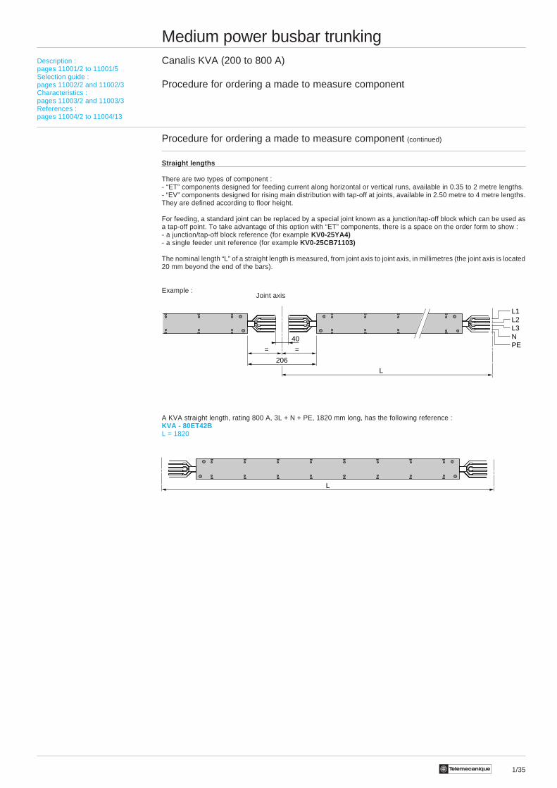
1/35Te
Medium power busbar trunkingCanalis KVA (200 to 800 A)
Procedure for ordering a made to measure component
Procedure for ordering a made to measure component (continued)
Straight lengths
There are two types of component :- “ET” components designed for feeding current along horizontal or vertical runs, available in 0.35 to 2 metre lengths.- “EV” components designed for rising main distribution with tap-off at joints, available in 2.50 metre to 4 metre lengths.They are defined according to floor height.
For feeding, a standard joint can be replaced by a special joint known as a junction/tap-off block which can be used asa tap-off point. To take advantage of this option with “ET” components, there is a space on the order form to show :- a junction/tap-off block reference (for example KV0-25YA4)- a single feeder unit reference (for example KV0-25CB71103)
The nominal length “L” of a straight length is measured, from joint axis to joint axis, in millimetres (the joint axis is located20 mm beyond the end of the bars).
Example :
A KVA straight length, rating 800 A, 3L + N + PE, 1820 mm long, has the following reference :KVA - 80ET42BL = 1820
L
Description :pages 11001/2 to 11001/5Selection guide :pages 11002/2 and 11002/3Characteristics :pages 11003/2 and 11003/3References :pages 11004/2 to 11004/13
Joint axis
40
206
L
==
L1L2L3NPE
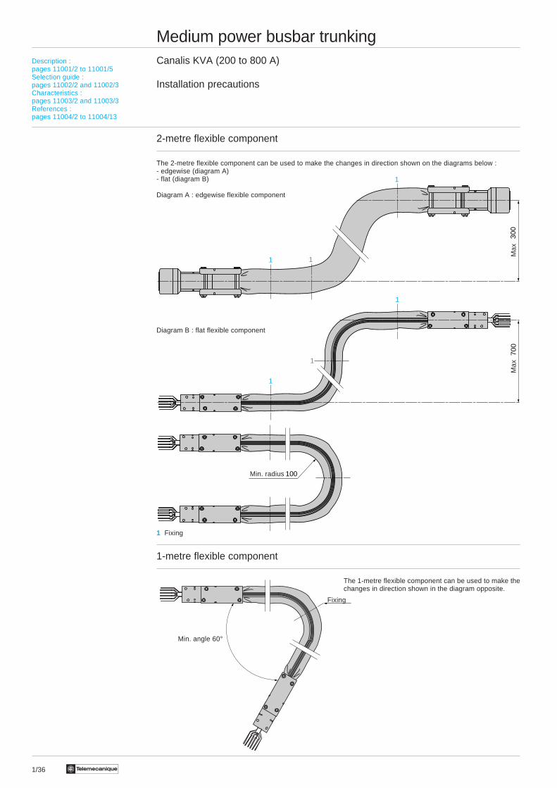
1/36 Te
Medium power busbar trunkingCanalis KVA (200 to 800 A)
Installation precautions
2-metre flexible component
The 2-metre flexible component can be used to make the changes in direction shown on the diagrams below :- edgewise (diagram A)- flat (diagram B)
Diagram A : edgewise flexible component
Diagram B : flat flexible component
1 Fixing
1-metre flexible component
The 1-metre flexible component can be used to make thechanges in direction shown in the diagram opposite.
Description :pages 11001/2 to 11001/5Selection guide :pages 11002/2 and 11002/3Characteristics :pages 11003/2 and 11003/3References :pages 11004/2 to 11004/13
300
700
100
1
1
1
1 1
1
Min. radius
Max
Max
Fixing
Min. angle 60°
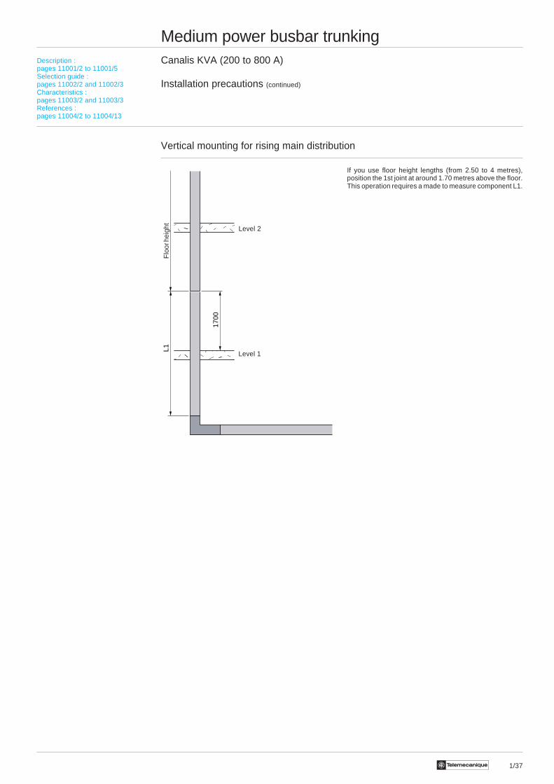
1/37Te
Medium power busbar trunkingCanalis KVA (200 to 800 A)
Installation precautions (continued)
Vertical mounting for rising main distribution
If you use floor height lengths (from 2.50 to 4 metres),position the 1st joint at around 1.70 metres above the floor.This operation requires a made to measure component L1.
Description :pages 11001/2 to 11001/5Selection guide :pages 11002/2 and 11002/3Characteristics :pages 11003/2 and 11003/3References :pages 11004/2 to 11004/13
L1 17
00
Level 2
Level 1
Flo
or h
eigh
t
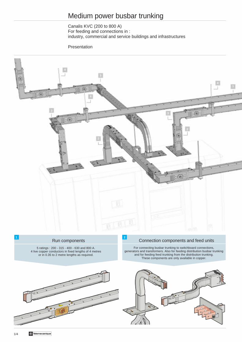
1/4 Te
Medium power busbar trunkingCanalis KVC (200 to 800 A)For feeding and connections in :industry, commercial and service buildings and infrastructures
Presentation
Connection components and feed units
For connecting busbar trunking to switchboard connections,generators and transformers. Also for feeding distribution busbar trunking
and for feeding feed trunking from the distribution trunking.These components are only available in copper.
Run components
5 ratings : 200 - 315 - 400 - 630 and 800 A.4 live copper conductors in fixed lengths of 4 metres
or in 0.35 to 2 metre lengths as required.
1 2
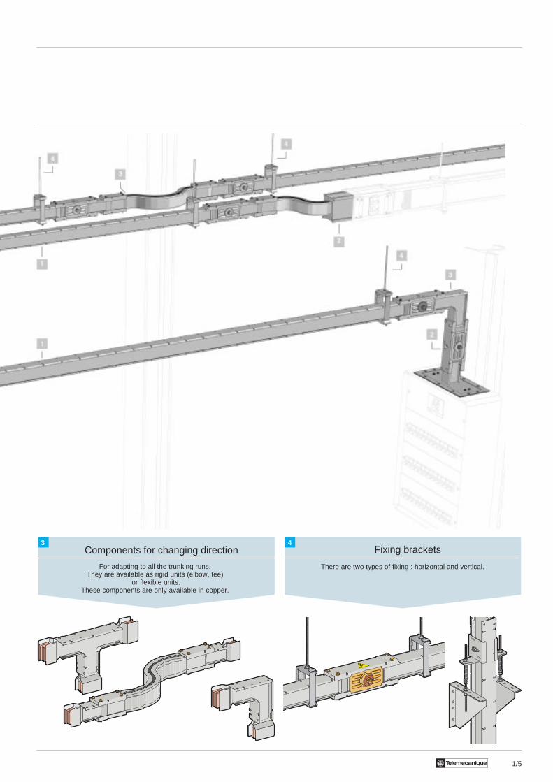
1/5Te
Components for changing direction
For adapting to all the trunking runs.They are available as rigid units (elbow, tee)
or flexible units.These components are only available in copper.
Fixing brackets
There are two types of fixing : horizontal and vertical.
3 4
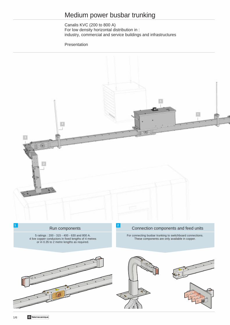
1/6 Te
Medium power busbar trunkingCanalis KVC (200 to 800 A)For low density horizontal distribution in :industry, commercial and service buildings and infrastructures
Presentation
Connection components and feed unitsRun components
For connecting busbar trunking to switchboard connections.These components are only available in copper.
5 ratings : 200 - 315 - 400 - 630 and 800 A.4 live copper conductors in fixed lengths of 4 metres
or in 0.35 to 2 metre lengths as required.
1 2
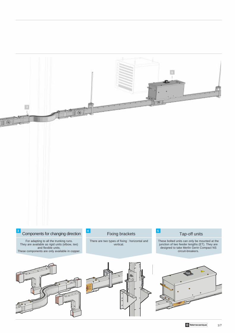
1/7Te
Components for changing direction Tap-off unitsFixing brackets
There are two types of fixing : horizontal andvertical.
For adapting to all the trunking runs.They are available as rigid units (elbow, tee)
and flexible units.These components are only available in copper.
These bolted units can only be mounted at thejunction of two feeder lengths (ET). They aredesigned to take Merlin Gerin Compact NS
circuit-breakers.
3 4 5
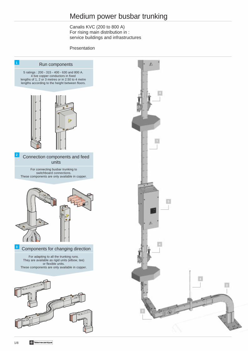
1/8 Te
Connection components and feedunits
Medium power busbar trunkingCanalis KVC (200 to 800 A)For rising main distribution in :service buildings and infrastructures
Presentation
Components for changing direction
Run components
For connecting busbar trunking toswitchboard connections.
These components are only available in copper.
5 ratings : 200 - 315 - 400 - 630 and 800 A.4 live copper conductors in fixed
lengths of 1, 2 or 3 metres or in 2.50 to 4 metrelengths according to the height between floors.
For adapting to all the trunking runs.They are available as rigid units (elbow, tee)
or flexible units.These components are only available in copper.
1
2
3
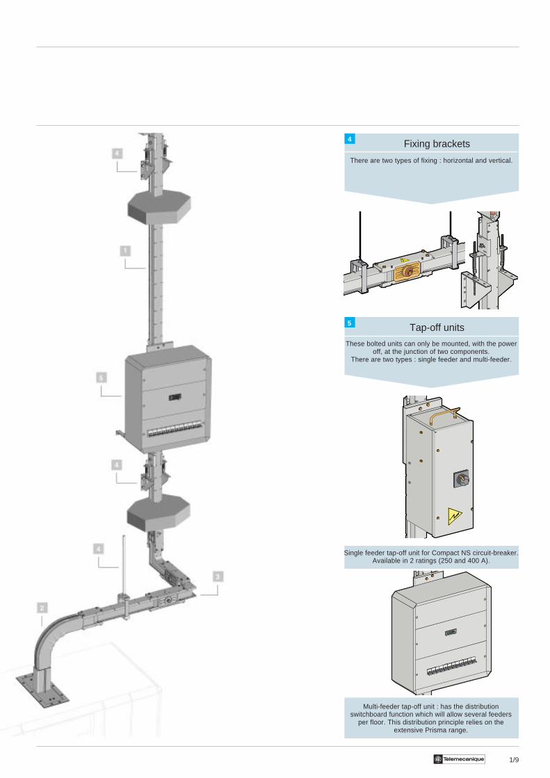
1/9Te
Fixing brackets
There are two types of fixing : horizontal and vertical.
Tap-off units
These bolted units can only be mounted, with the poweroff, at the junction of two components.
There are two types : single feeder and multi-feeder.
Single feeder tap-off unit for Compact NS circuit-breaker.Available in 2 ratings (250 and 400 A).
Multi-feeder tap-off unit : has the distributionswitchboard function which will allow several feeders
per floor. This distribution principle relies on theextensive Prisma range.
4
5
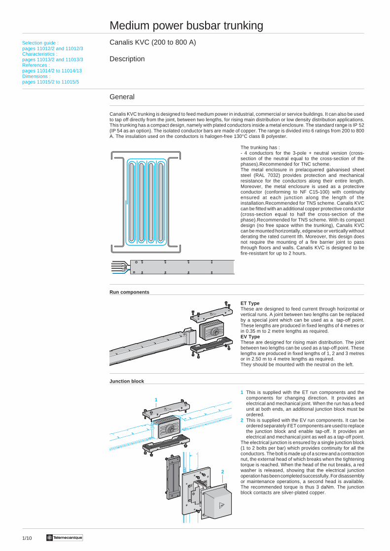
Te1/10
Medium power busbar trunkingCanalis KVC (200 to 800 A)
Description
General
Canalis KVC trunking is designed to feed medium power in industrial, commercial or service buildings. It can also be usedto tap off directly from the joint, between two lengths, for rising main distribution or low density distribution applications.This trunking has a compact design, namely with plated conductors inside a metal enclosure. The standard range is IP 52(IP 54 as an option). The isolated conductor bars are made of copper. The range is divided into 6 ratings from 200 to 800A. The insulation used on the conductors is halogen-free 130°C class B polyester.
The trunking has :- 4 conductors for the 3-pole + neutral version (cross-section of the neutral equal to the cross-section of thephases).Recommended for TNC scheme.The metal enclosure in prelacquered galvanised sheetsteel (RAL 7032) provides protection and mechanicalresistance for the conductors along their entire length.Moreover, the metal enclosure is used as a protectiveconductor (conforming to NF C15-100) with continuityensured at each junction along the length of theinstallation.Recommended for TNS scheme. Canalis KVCcan be fitted with an additional copper protective conductor(cross-section equal to half the cross-section of thephase).Recommended for TNS scheme. With its compactdesign (no free space within the trunking), Canalis KVCcan be mounted horizontally, edgewise or vertically withoutderating the rated current Ith. Moreover, this design doesnot require the mounting of a fire barrier joint to passthrough floors and walls. Canalis KVC is designed to befire-resistant for up to 2 hours.
Run components
ET TypeThese are designed to feed current through horizontal orvertical runs. A joint between two lengths can be replacedby a special joint which can be used as a tap-off point.These lengths are produced in fixed lengths of 4 metres orin 0.35 m to 2 metre lengths as required.EV TypeThese are designed for rising main distribution. The jointbetween two lengths can be used as a tap-off point. Theselengths are produced in fixed lengths of 1, 2 and 3 metresor in 2.50 m to 4 metre lengths as required.They should be mounted with the neutral on the left.
Junction block
1 This is supplied with the ET run components and thecomponents for changing direction. It provides anelectrical and mechanical joint. When the run has a feedunit at both ends, an additional junction block must beordered.
2 This is supplied with the EV run components. It can beordered separately if ET components are used to replacethe junction block and enable tap-off. It provides anelectrical and mechanical joint as well as a tap-off point.
The electrical junction is ensured by a single junction block(1 to 2 bolts per bar) which provides continuity for all theconductors. The bolt is made up of a screw and a contractionnut, the external head of which breaks when the tighteningtorque is reached. When the head of the nut breaks, a redwasher is released, showing that the electrical junctionoperation has been completed successfully. For disassemblyor maintenance operations, a second head is available.The recommended torque is thus 3 daNm. The junctionblock contacts are silver-plated copper.
Selection guide :pages 11012/2 and 11012/3Characteristics :pages 11013/2 and 11013/3References :pages 11014/2 to 11014/13Dimensions :pages 11015/2 to 11015/5
1
2
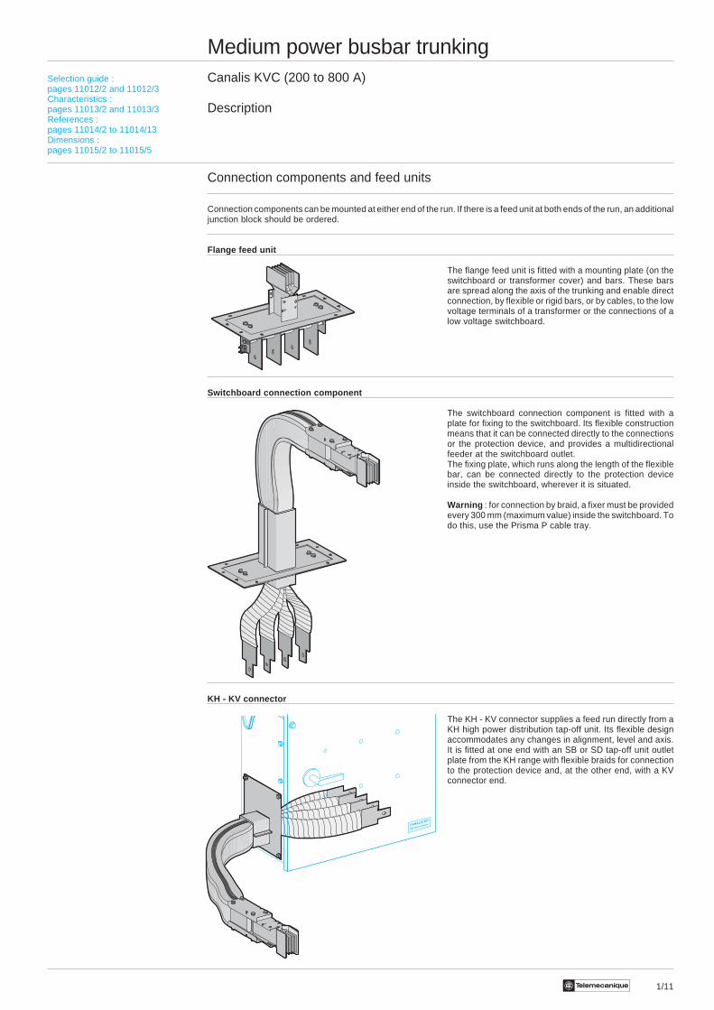
1/11Te
Medium power busbar trunkingCanalis KVC (200 to 800 A)
Description
Connection components and feed units
Connection components can be mounted at either end of the run. If there is a feed unit at both ends of the run, an additionaljunction block should be ordered.
Flange feed unit
The flange feed unit is fitted with a mounting plate (on theswitchboard or transformer cover) and bars. These barsare spread along the axis of the trunking and enable directconnection, by flexible or rigid bars, or by cables, to the lowvoltage terminals of a transformer or the connections of alow voltage switchboard.
Switchboard connection component
The switchboard connection component is fitted with aplate for fixing to the switchboard. Its flexible constructionmeans that it can be connected directly to the connectionsor the protection device, and provides a multidirectionalfeeder at the switchboard outlet.The fixing plate, which runs along the length of the flexiblebar, can be connected directly to the protection deviceinside the switchboard, wherever it is situated.
Warning : for connection by braid, a fixer must be providedevery 300 mm (maximum value) inside the switchboard. Todo this, use the Prisma P cable tray.
KH - KV connector
The KH - KV connector supplies a feed run directly from aKH high power distribution tap-off unit. Its flexible designaccommodates any changes in alignment, level and axis.It is fitted at one end with an SB or SD tap-off unit outletplate from the KH range with flexible braids for connectionto the protection device and, at the other end, with a KVconnector end.
Selection guide :pages 11012/2 and 11012/3Characteristics :pages 11013/2 and 11013/3References :pages 11014/2 to 11014/13Dimensions :pages 11015/2 to 11015/5
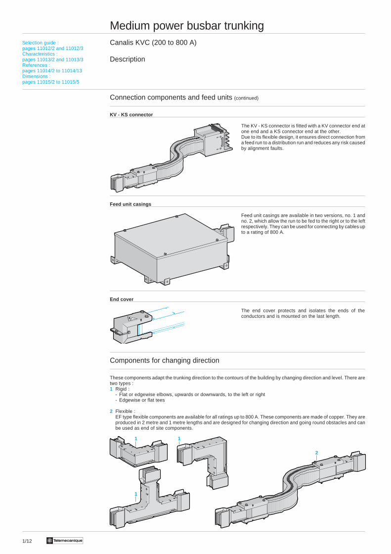
1/12 Te
Medium power busbar trunkingCanalis KVC (200 to 800 A)
Description
Connection components and feed units (continued)
KV - KS connector
The KV - KS connector is fitted with a KV connector end atone end and a KS connector end at the other.Due to its flexible design, it ensures direct connection froma feed run to a distribution run and reduces any risk causedby alignment faults.
Feed unit casings
Feed unit casings are available in two versions, no. 1 andno. 2, which allow the run to be fed to the right or to the leftrespectively. They can be used for connecting by cables upto a rating of 800 A.
End cover
The end cover protects and isolates the ends of theconductors and is mounted on the last length.
Components for changing direction
These components adapt the trunking direction to the contours of the building by changing direction and level. There aretwo types :1 Rigid :
- Flat or edgewise elbows, upwards or downwards, to the left or right- Edgewise or flat tees
2 Flexible :EF type flexible components are available for all ratings up to 800 A. These components are made of copper. They areproduced in 2 metre and 1 metre lengths and are designed for changing direction and going round obstacles and canbe used as end of site components.
Selection guide :pages 11012/2 and 11012/3Characteristics :pages 11013/2 and 11013/3References :pages 11014/2 to 11014/13Dimensions :pages 11015/2 to 11015/5
1
1
1
2
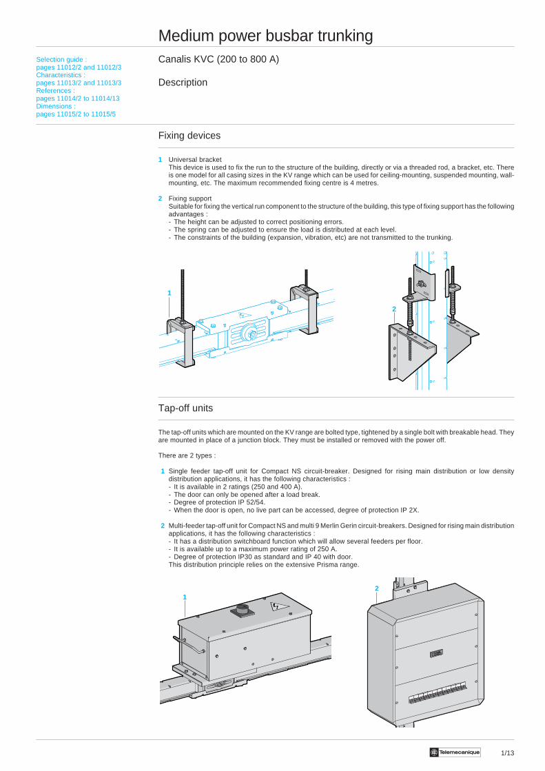
1/13Te
Medium power busbar trunkingCanalis KVC (200 to 800 A)
Description
Fixing devices
1 Universal bracketThis device is used to fix the run to the structure of the building, directly or via a threaded rod, a bracket, etc. Thereis one model for all casing sizes in the KV range which can be used for ceiling-mounting, suspended mounting, wall-mounting, etc. The maximum recommended fixing centre is 4 metres.
2 Fixing supportSuitable for fixing the vertical run component to the structure of the building, this type of fixing support has the followingadvantages :- The height can be adjusted to correct positioning errors.- The spring can be adjusted to ensure the load is distributed at each level.- The constraints of the building (expansion, vibration, etc) are not transmitted to the trunking.
Tap-off units
The tap-off units which are mounted on the KV range are bolted type, tightened by a single bolt with breakable head. Theyare mounted in place of a junction block. They must be installed or removed with the power off.
There are 2 types :
1 Single feeder tap-off unit for Compact NS circuit-breaker. Designed for rising main distribution or low densitydistribution applications, it has the following characteristics :- It is available in 2 ratings (250 and 400 A).- The door can only be opened after a load break.- Degree of protection IP 52/54.- When the door is open, no live part can be accessed, degree of protection IP 2X.
2 Multi-feeder tap-off unit for Compact NS and multi 9 Merlin Gerin circuit-breakers. Designed for rising main distributionapplications, it has the following characteristics :- It has a distribution switchboard function which will allow several feeders per floor.- It is available up to a maximum power rating of 250 A.- Degree of protection IP30 as standard and IP 40 with door.This distribution principle relies on the extensive Prisma range.
2
Selection guide :pages 11012/2 and 11012/3Characteristics :pages 11013/2 and 11013/3References :pages 11014/2 to 11014/13Dimensions :pages 11015/2 to 11015/5
21
1
1/14 Te
Medium power busbar trunkingCanalis KVC (200 to 800 A)
Selection guide
Determining the rating according to the temperature rise
The rating of a busbar trunking, in amps, represents the maximum intensity of the constant current which the trunking cancontinuously support, for an average ambient temperature of 35 °C, and in accordance with standard temperature rises(IEC 439.2).
Determining the rating according to the temperature rise consists of selecting the busbar trunking rating immediatelyabove the operating current of the installation. However, as a rule, the intensity of the current which crosses a busbartrunking is constantly fluctuating. The operating current is therefore defined as that of the constant current which producesthe same thermal effects as the actual current.
It is sometimes difficult to determine the operating current, especially when there is no reading for the installation or foran equivalent installation. The operating current can be estimated with sufficient precision by calculating the product ofthe nominal currents of receivers connected to the busbar trunking by a coefficient known as the “average demandcoefficient”. The average demand coefficient is empirically determined by comparison with existing installations. It isdependent upon :- the average quantity of receivers operating- the load variation of each receiver (a receiver rarely absorbs its maximum power, as peak periods alternate with those
of no-load operation)- whether several receivers are operating at the same time, whether peaks are superimposed and the duration of these
peaks
As an example, here are a few coefficients for a general mechanical engineering workshop.
Number of receivers Average demand coefficient
2 or 3 0.9
4 or 5 0.8
6 to 9 0.7
10 to 40 0.6
40 plus 0.5
Depending on the ambient temperature, the trunking must be derated (see characteristics pages 11013/2 and 11013/3).
Checking the rating according to the permissible voltage drop
The permissible voltage drop is that which is compatible with the correct operation of receivers (refer to the manufacturers'manuals).
i Read the voltage drop in mV/m/A in the tables on page 11013/3 for the busbar trunking selected according to thetemperature rise.
i Determine the voltage drop for the most disadvantaged receivers, namely those which are the furthest from the sourceand for the highest current. If the voltage drop is not permissible, select the rating immediately above.
i Repeat the checking procedure for the new rating.
Checking the rating according to withstand to short-circuit currents
i Calculate the intensity of the short-circuit current at the points which are considered to be unfavourable.
i Check, by referring to the tables on pages 11013/2 and 11013/3, that the selected rating of the trunking enables it towithstand this short-circuit current. If this is not the case, there are two possible solutions :- Select trunking of a higher rating and repeat the checking procedure.- Provide a protection system which limits current peaks upstream of the trunking.
Description :pages 11011/2 to 11011/5Characteristics :pages 11013/2 and 11013/3References :pages 11014/2 to 11014/13Dimensions :pages 11015/2 to 11015/5

1/15Te
Description :pages 11011/2 to 11011/5Characteristics :pages 11013/2 and 11013/3References :pages 11014/2 to 11014/13Dimensions :pages 11015/2 to 11015/5
Medium power busbar trunkingCanalis KVC (200 to 800 A)
Selection guide
Example of selecting the rating of the busbar trunking
The table below can be used to determine the rating of the KVC busbar trunking (copper conductors) according to thepower of the transformer.
Transformer (U2 = 410 V) Canalis busbar trunkingPower Nominal Short-circuit Type Nominal Short-circuit
current current current currentkVA A kA A kA rms
100 141 4 KVC-20 200 7.2
160 225 6 KVC-31 315 17
250 352 9 KVC-40 400 19
400 563 14 KVC-63 630 31
500 704 17.6 KVC-80 800 41
Calculation assumptionsThe following calculation assumptions have been made :- the short-circuit power of the upstream supply : 500 MVA- the voltage ratio of the transformers : 20 kV/400 V
The circuit-breaker/trunking coordination table below gives directly the maximum short-circuit current for which the KVCtrunking is protected, according to the type of circuit-breaker.
Type of trunking KVC-20 KVC-31 KVC-40 KVC-63 KVC-80
Rating (A) 200 315 400 630 800
Merlin-Gerin NS250 N 35Compact H 70circuit-breaker L 100
NS 400 N 35 45 45 45H 35 70 70 70L 35 150 150 150
NS 630 N 45 45 45H 70 70 70L 150 150 150
C 801 N 40 50C1001 H 40 60
L 70 110
Masterpact M 08 N1 33 40circuit-breaker M 10 H1 33 40
H2 33 40L1 40 55
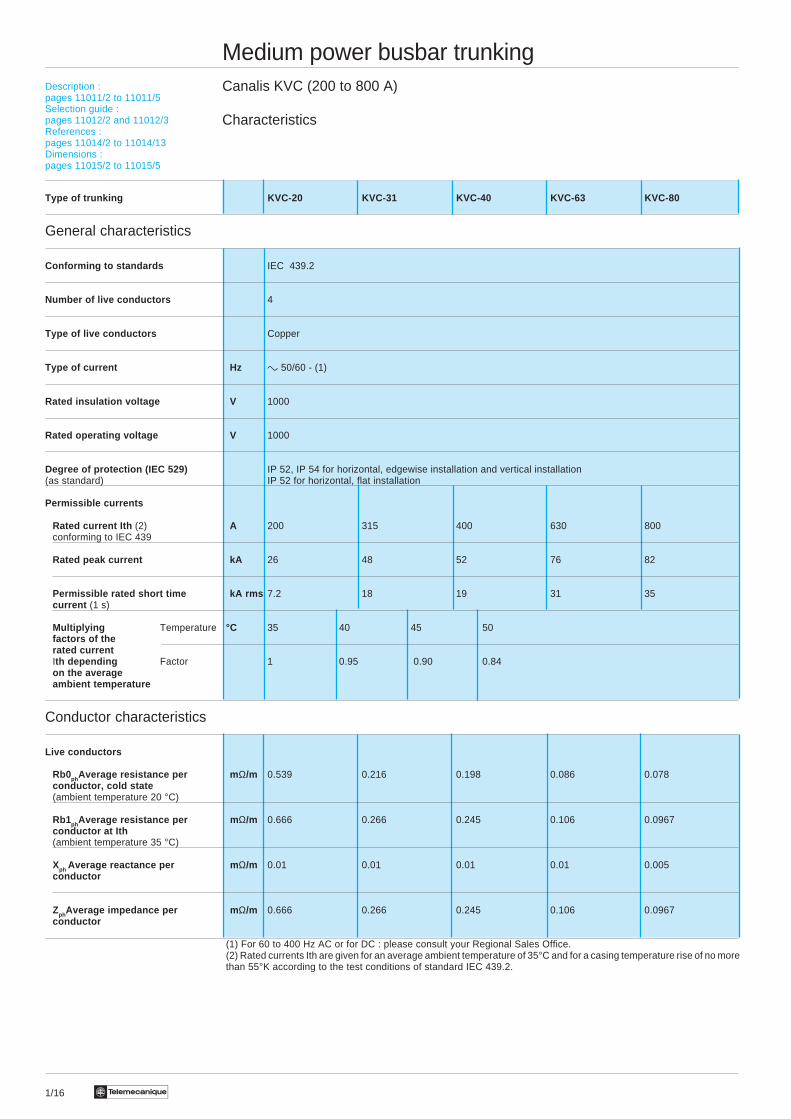
1/16 Te
Description :pages 11011/2 to 11011/5Selection guide :pages 11012/2 and 11012/3References :pages 11014/2 to 11014/13Dimensions :pages 11015/2 to 11015/5
Medium power busbar trunkingCanalis KVC (200 to 800 A)
Characteristics
Type of trunking KVC-20 KVC-31 KVC-40 KVC-63 KVC-80
General characteristics
Conforming to standards IEC 439.2
Number of live conductors 4
Type of live conductors Copper
Type of current Hz c 50/60 - (1)
Rated insulation voltage V 1000
Rated operating voltage V 1000
Degree of protection (IEC 529) IP 52, IP 54 for horizontal, edgewise installation and vertical installation(as standard) IP 52 for horizontal, flat installation
Permissible currents
Rated current Ith (2) A 200 315 400 630 800conforming to IEC 439
Rated peak current kA 26 48 52 76 82
Permissible rated short time kA rms 7.2 18 19 31 35current (1 s)
Multiplying Temperature °C 35 40 45 50factors of therated currentIth depending Factor 1 0.95 0.90 0.84on the averageambient temperature
Conductor characteristics
Live conductors
Rb0phAverage resistance per m Ω/m 0.539 0.216 0.198 0.086 0.078conductor, cold state(ambient temperature 20 °C)
Rb1phAverage resistance per m Ω/m 0.666 0.266 0.245 0.106 0.0967conductor at Ith(ambient temperature 35 °C)
Xph Average reactance per m Ω/m 0.01 0.01 0.01 0.01 0.005conductor
ZphAverage impedance per m Ω/m 0.666 0.266 0.245 0.106 0.0967conductor
(1) For 60 to 400 Hz AC or for DC : please consult your Regional Sales Office.(2) Rated currents Ith are given for an average ambient temperature of 35°C and for a casing temperature rise of no morethan 55°K according to the test conditions of standard IEC 439.2.
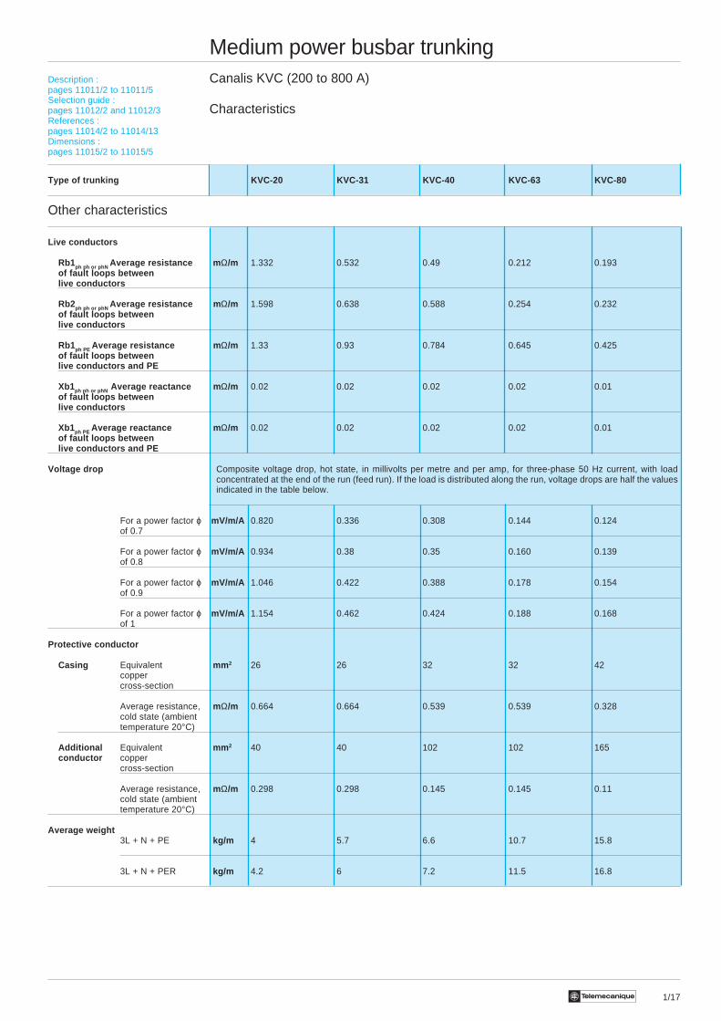
1/17Te
Description :pages 11011/2 to 11011/5Selection guide :pages 11012/2 and 11012/3References :pages 11014/2 to 11014/13Dimensions :pages 11015/2 to 11015/5
Medium power busbar trunkingCanalis KVC (200 to 800 A)
Characteristics
Type of trunking KVC-20 KVC-31 KVC-40 KVC-63 KVC-80
Other characteristics
Live conductors
Rb1ph ph or phN Average resistance m Ω/m 1.332 0.532 0.49 0.212 0.193of fault loops betweenlive conductors
Rb2ph ph or phN Average resistance m Ω/m 1.598 0.638 0.588 0.254 0.232of fault loops betweenlive conductors
Rb1ph PE Average resistance m Ω/m 1.33 0.93 0.784 0.645 0.425of fault loops betweenlive conductors and PE
Xb1ph ph or phN Average reactance m Ω/m 0.02 0.02 0.02 0.02 0.01of fault loops betweenlive conductors
Xb1ph PE Average reactance m Ω/m 0.02 0.02 0.02 0.02 0.01of fault loops betweenlive conductors and PE
Voltage drop Composite voltage drop, hot state, in millivolts per metre and per amp, for three-phase 50 Hz current, with loadconcentrated at the end of the run (feed run). If the load is distributed along the run, voltage drops are half the valuesindicated in the table below.
For a power factor ϕ mV/m/A 0.820 0.336 0.308 0.144 0.124of 0.7
For a power factor ϕ mV/m/A 0.934 0.38 0.35 0.160 0.139of 0.8
For a power factor ϕ mV/m/A 1.046 0.422 0.388 0.178 0.154of 0.9
For a power factor ϕ mV/m/A 1.154 0.462 0.424 0.188 0.168of 1
Protective conductor
Casing Equivalent mm 2 26 26 32 32 42coppercross-section
Average resistance, mΩ/m 0.664 0.664 0.539 0.539 0.328cold state (ambienttemperature 20°C)
Additional Equivalent mm 2 40 40 102 102 165conductor copper
cross-section
Average resistance, mΩ/m 0.298 0.298 0.145 0.145 0.11cold state (ambienttemperature 20°C)
Average weight3L + N + PE kg/m 4 5.7 6.6 10.7 15.8
3L + N + PER kg/m 4.2 6 7.2 11.5 16.8

Te1/18
KVC-iiETiiiKVC-iiEViii
KVC-iiETiii
KVC-iiEViiiKVC-iiETiii
KVC-iiETiiiKVC-iiEViii

1/19Te
Medium power busbar trunkingCanalis KVC (200 to 800 A)Run components for horizontal and vertical feeding. IP 52
References
Straight lengths (1)
Rating Type Length 3L + N + PE 3L + N + PERMin…Max Reference Reference
A mm Weight (kg) Weight (kg)
200 Fixed 4000 KVC-20ET440 KVC-20ET74015.60 16.50
315 Fixed 4000 KVC-31ET440 KVC-31ET74022.80 24.00
Made to measure 350…2000 KVC-31ET42B KVC-31ET72B12.00 12.60
400 Fixed 4000 KVC-40ET440 KVC-40ET74026.20 29.40
630 Fixed 4000 KVC-63ET440 KVC-63ET74042.60 45.80
Made to measure 350…2000 KVC-63ET42B KVC-63ET72B22.20 23.80
800 Fixed 4000 KVC-80ET440 KVC-80ET74063.00 67.00
Made to measure 350…2000 KVC-80ET42B KVC-80ET72B33.00 35.00
Junction block, IP 54 (2)
Busbar trunking rating 3L + N + PE3L + N + PERReference Weight
A kg
200 and 315 KV0-31YA4 1.20
400 and 630 KV0-63YA4 1.80
800 KV0-80YA4 3.00
(1) To order a made to measure component, see the procedure on pages 11016/2 and 11016/3.(2) Only order if the run has a feed unit at each end.
Description :pages 11011/2 to 11011/5Selection guide :pages 11012/2 and 11012/3Characteristics :pages 11013/2 and 11013/3Dimensions :pages 11015/2 to 11015/5
N : position of neutral
N

Te1/20
Medium power busbar trunkingCanalis KVC (200 to 800 A)Run components for rising main distribution, IP 52
References
Straight lengths (1)
Rating Type Lengths 3L + N + PE 3L + N + PERMin…Max Reference Reference
A mm Weight (kg) Weight (kg)
200 Fixed 3000 KVC-20EV430 KVC-20EV73012.00 12.60
2000 KVC-20EV420 KVC-20EV7208.40 8.40
1000 KVC-20EV410 KVC-20EV7104.80 5.10
Made to measure 2500…3000 KVC-20EV43D KVC-20EV73D12.00 12.60
3001…3500 KVC-20EV43E KVC-20EV73E13.80 13.50
3501…4000 KVC-20EV44F KVC-20EV74F15.60 16.50
315 Fixed 3000 KVC-31EV430 KVC-31EV73017.40 18.30
2000 KVC-31EV420 KVC-31EV72012.00 12.60
1000 KVC-31EV410 KVC-31EV7106,60 7.05
Made to measure 2500…3000 KVC-31EV43D KVC-31EV73D17.40 18.30
3001…3500 KVC-31EV43E KVC-31EV73E20.10 21.15
3501…4000 KVC-31EV44F KVC-31EV74F22.80 24.00
400 Fixed 3000 KVC-40EV430 KVC-40EV73020.10 22.50
2000 KVC-40EV420 KVC-40EV72014.00 15.60
1000 KVC-40EV410 KVC-40EV7107.90 8.70
Made to measure 2500…3000 KVC-40EV43D KVC-40EV73D20.10 22.50
3001…3500 KVC-40EV43E KVC-40EV73E23.15 25.95
3501…4000 KVC-40EV44F KVC-40EV74F26.20 29.40
(1) To order a made to measure component, see the procedure on pages 11016/2 and 11016/3.
Description :pages 11011/2 to 11011/5Selection guide :pages 11012/2 and 11012/3Characteristics :pages 11013/2 and 11013/3Dimensions :pages 11015/2 to 11015/5
N : position of neutral
N
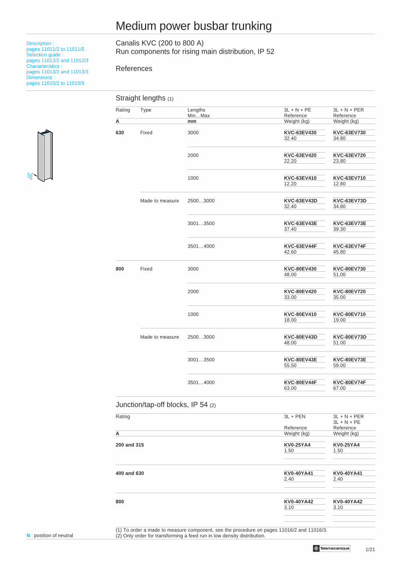
Te 1/21
Medium power busbar trunkingCanalis KVC (200 to 800 A)Run components for rising main distribution, IP 52
References
Straight lengths (1)
Rating Type Lengths 3L + N + PE 3L + N + PERMin…Max Reference Reference
A mm Weight (kg) Weight (kg)
630 Fixed 3000 KVC-63EV430 KVC-63EV73032.40 34.80
2000 KVC-63EV420 KVC-63EV72022.20 23.80
1000 KVC-63EV410 KVC-63EV71012.20 12.80
Made to measure 2500…3000 KVC-63EV43D KVC-63EV73D32.40 34.80
3001…3500 KVC-63EV43E KVC-63EV73E37.40 39.30
3501…4000 KVC-63EV44F KVC-63EV74F42.60 45.80
800 Fixed 3000 KVC-80EV430 KVC-80EV73048.00 51.00
2000 KVC-80EV420 KVC-80EV72033.00 35.00
1000 KVC-80EV410 KVC-80EV71018.00 19.00
Made to measure 2500…3000 KVC-80EV43D KVC-80EV73D48.00 51.00
3001…3500 KVC-80EV43E KVC-80EV73E55.50 59.00
3501…4000 KVC-80EV44F KVC-80EV74F63.00 67.00
Junction/tap-off blocks, IP 54 (2)
Rating 3L + PEN 3L + N + PER3L + N + PE
Reference ReferenceA Weight (kg) Weight (kg)
200 and 315 KV0-25YA4 KV0-25YA41.50 1.50
400 and 630 KV0-40YA41 KV0-40YA412.40 2.40
800 KV0-40YA42 KV0-40YA423.10 3.10
(1) To order a made to measure component, see the procedure on pages 11016/2 and 11016/3.(2) Only order for transforming a feed run in low density distribution.
Description :pages 11011/2 to 11011/5Selection guide :pages 11012/2 and 11012/3Characteristics :pages 11013/2 and 11013/3Dimensions :pages 11015/2 to 11015/5
N : position of neutral
N
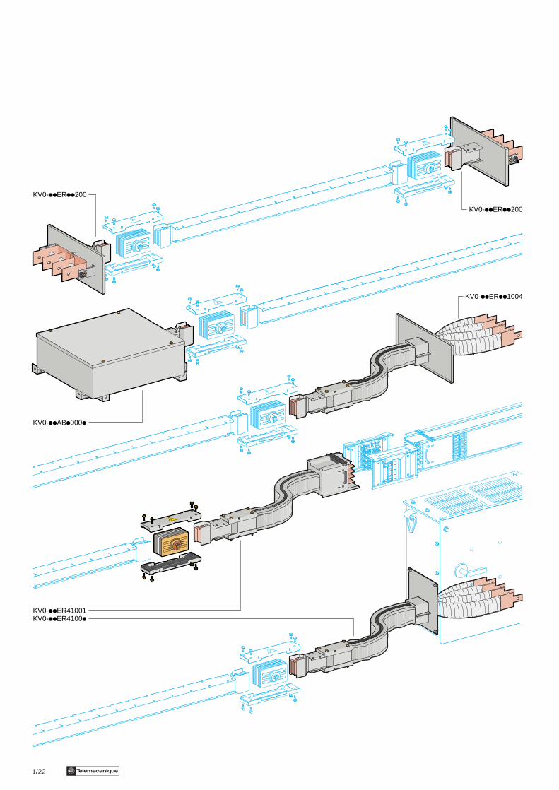
1/22 Te
KV0-iiERii200
KV0-iiERii1004
KV0-iiER41001KV0-iiER4100i
KV0-iiABi000i
KV0-iiERii200
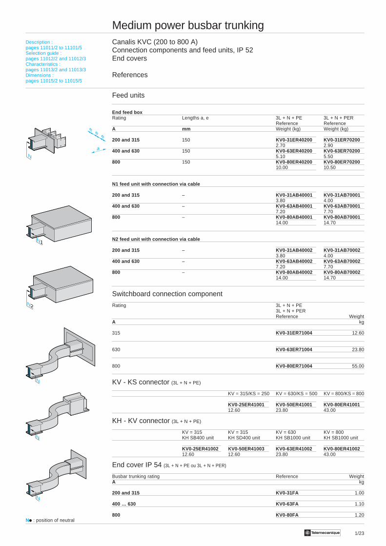
1/23Te
Medium power busbar trunkingCanalis KVC (200 to 800 A)Connection components and feed units, IP 52End covers
References
Feed units
End feed boxRating Lengths a, e 3L + N + PE 3L + N + PER
Reference ReferenceA mm Weight (kg) Weight (kg)
200 and 315 150 KV0-31ER40200 KV0-31ER702002.70 2.90
400 and 630 150 KV0-63ER40200 KV0-63ER702005.10 5.50
800 150 KV0-80ER40200 KV0-80ER7020010.00 10.50
N1 feed unit with connection via cable
200 and 315 – KV0-31AB40001 KV0-31AB700013.80 4.00
400 and 630 – KV0-63AB40001 KV0-63AB700017.20 7.70
800 – KV0-80AB40001 KV0-80AB7000114.00 14.70
N2 feed unit with connection via cable
200 and 315 – KV0-31AB40002 KV0-31AB700023.80 4.00
400 and 630 – KV0-63AB40002 KV0-63AB700027.20 7.70
800 – KV0-80AB40002 KV0-80AB7000214.00 14.70
Switchboard connection component
Rating 3L + N + PE3L + N + PERReference Weight
A kg
315 KV0-31ER71004 12.60
630 KV0-63ER71004 23.80
800 KV0-80ER71004 55.00
KV - KS connector (3L + N + PE)
KV = 315/KS = 250 KV = 630/KS = 500 KV = 800/KS = 800
KV0-25ER41001 KV0-50ER41001 KV0-80ER4100112.60 23.80 43.00
KH - KV connector (3L + N + PE)
KV = 315 KV = 315 KV = 630 KV = 800KH SB400 unit KH SD400 unit KH SB1000 unit KH SB1000 unit
KV0-25ER41002 KV0-50ER41003 KV0-63ER41002 KV0-80ER4100212.60 12.60 23.80 43.00
End cover IP 54 (3L + N + PE ou 3L + N + PER)
Busbar trunking rating Reference WeightA kg
200 and 315 KV0-31FA 1.00
400 … 630 KV0-63FA 1.10
800 KV0-80FA 1.20
Description :pages 11011/2 to 11101/5Selection guide :pages 11012/2 and 11012/3Characteristics :pages 11013/2 and 11013/3Dimensions :pages 11015/2 to 11015/5
N
a
ee
e
N
N2
N1
N
N
Ni : position of neutral

1/24 Te
KV0-iiEFii0
KV0-iiLCi05
KV0-iiLCi05
KV0-iiLPi042
KV0-iiLPi042KV0-iiLPi041
KV0-iiLPi041
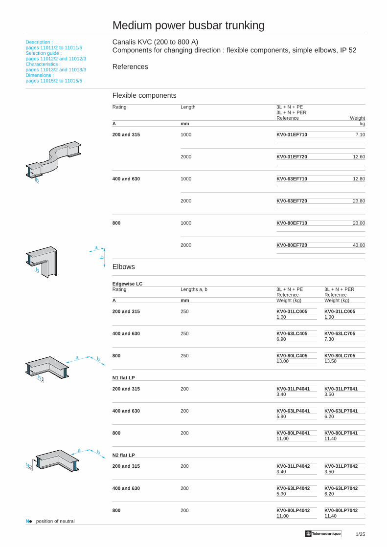
1/25Te
Medium power busbar trunkingCanalis KVC (200 to 800 A)Components for changing direction : flexible components, simple elbows, IP 52
References
Flexible components
Rating Length 3L + N + PE3L + N + PERReference Weight
A mm kg
200 and 315 1000 KV0-31EF710 7.10
2000 KV0-31EF720 12.60
400 and 630 1000 KV0-63EF710 12.80
2000 KV0-63EF720 23.80
800 1000 KV0-80EF710 23.00
2000 KV0-80EF720 43.00
Elbows
Edgewise LCRating Lengths a, b 3L + N + PE 3L + N + PER
Reference ReferenceA mm Weight (kg) Weight (kg)
200 and 315 250 KV0-31LC005 KV0-31LC0051.00 1.00
400 and 630 250 KV0-63LC405 KV0-63LC7056.90 7.30
800 250 KV0-80LC405 KV0-80LC70513.00 13.50
N1 flat LP
200 and 315 200 KV0-31LP4041 KV0-31LP70413.40 3.50
400 and 630 200 KV0-63LP4041 KV0-63LP70415.90 6.20
800 200 KV0-80LP4041 KV0-80LP704111.00 11.40
N2 flat LP
200 and 315 200 KV0-31LP4042 KV0-31LP70423.40 3.50
400 and 630 200 KV0-63LP4042 KV0-63LP70425.90 6.20
800 200 KV0-80LP4042 KV0-80LP704211.00 11.40
a b
a b
N1
N
a
b
N
N2
Description :pages 11011/2 to 11011/5Selection guide :pages 11012/2 and 11012/3Characteristics :pages 11013/2 and 11013/3Dimensions :pages 11015/2 to 11015/5
Ni : position of neutral
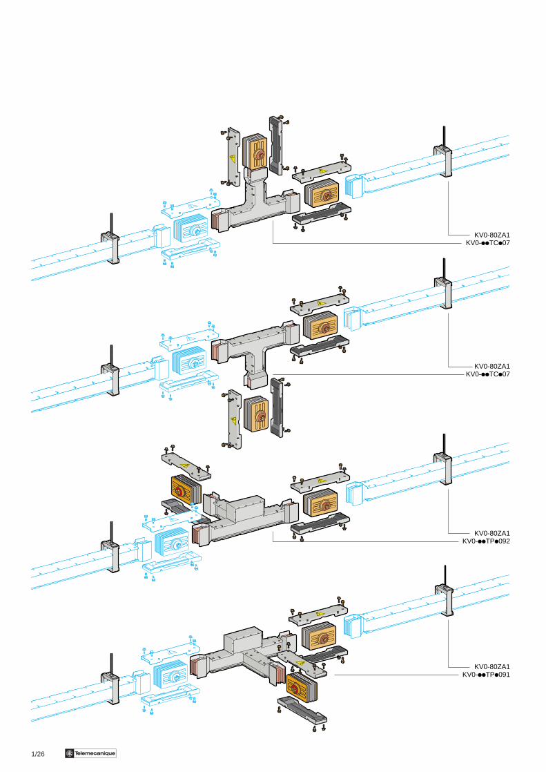
1/26 Te
KV0-80ZA1KV0-iiTCi07
KV0-80ZA1KV0-iiTCi07
KV0-80ZA1KV0-iiTPi092
KV0-80ZA1KV0-iiTPi091
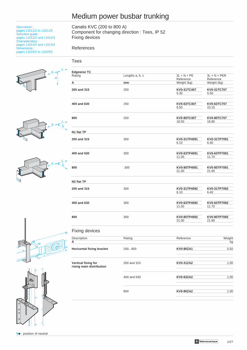
1/27Te
Medium power busbar trunkingCanalis KVC (200 to 800 A)Component for changing direction : Tees, IP 52Fixing devices
References
Tees
Edgewise TCRating Lengths a, b, c 3L + N + PE 3L + N + PER
Reference ReferenceA mm Weight (kg) Weight (kg)
200 and 315 250 KV0-31TC407 KV0-31TC7075.30 5.50
400 and 630 250 KV0-63TC407 KV0-63TC7079.50 10.10
800 250 KV0-80TC407 KV0-80TC70718.00 18.80
N1 flat TP
200 and 315 300 KV0-31TP4091 KV0-31TP70916.10 6.40
400 and 630 300 KV0-63TP4091 KV0-63TP709111.00 11.70
800 300 KV0-80TP4091 KV0-80TP709121.00 21.90
N2 flat TP
200 and 315 300 KV0-31TP4092 KV0-31TP70926.10 6.40
400 and 630 300 KV0-63TP4092 KV0-63TP709211.00 11.70
800 300 KV0-80TP4092 KV0-80TP709221.00 21.90
Fixing devices
Description Rating Reference WeightA kg
Horizontal fixing bracket 200...800 KV0-80ZA1 0.50
Vertical fixing for 200 and 315 KV0-31ZA2 1.00rising main distribution
400 and 630 KV0-63ZA2 1.00
800 KV0-80ZA2 1.00
Description :pages 11011/2 to 11011/5Selection guide :pages 11012/2 and 11012/3Characteristics :pages 11013/2 and 11013/3Dimensions :pages 11015/2 to 11015/5
Ni : position of neutral
ac
b
N
bac
N1
N2
bac
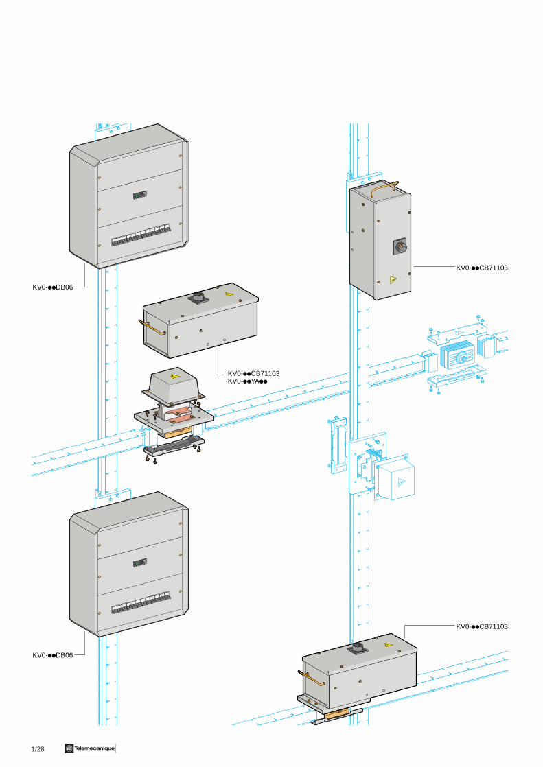
1/28 Te
KV0-iiCB71103KV0-iiYAii
KV0-iiCB71103
KV0-iiCB71103
KV0-iiDB06
KV0-iiDB06
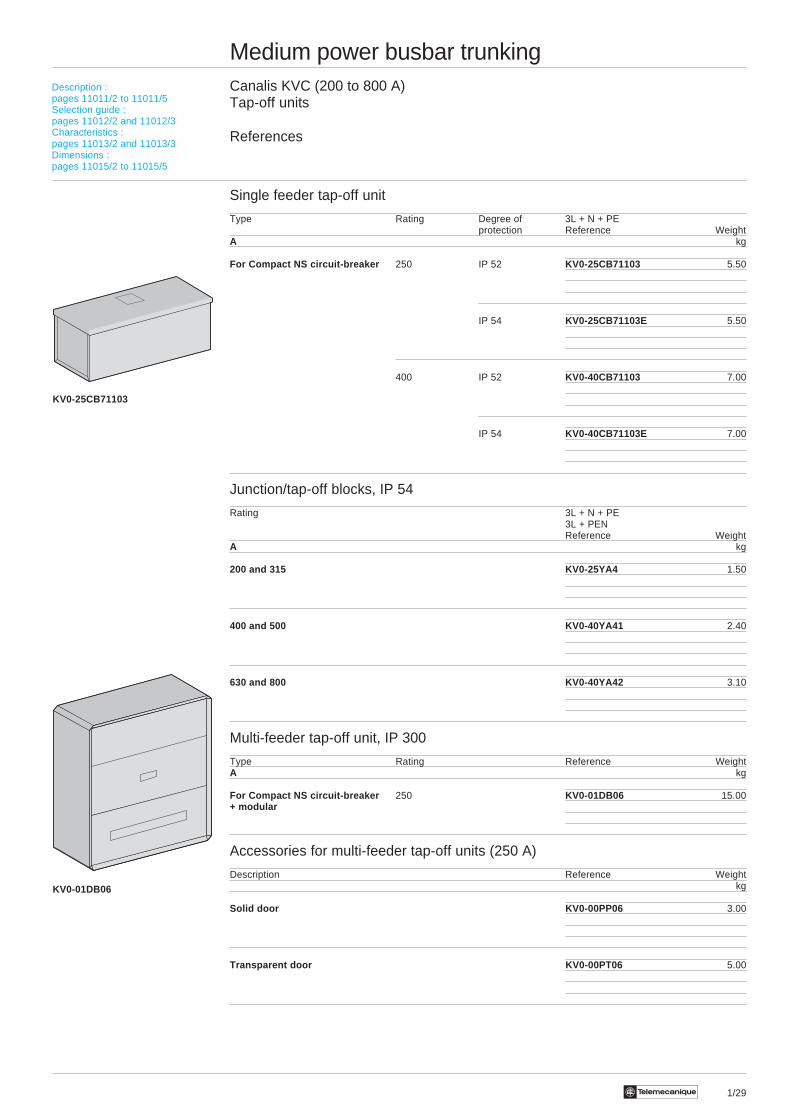
1/29Te
Medium power busbar trunkingCanalis KVC (200 to 800 A)Tap-off units
References
Single feeder tap-off unit
Type Rating Degree of 3L + N + PEprotection Reference Weight
A kg
For Compact NS circuit-breaker 250 IP 52 KV0-25CB71103 5.50
IP 54 KV0-25CB71103E 5.50
400 IP 52 KV0-40CB71103 7.00
IP 54 KV0-40CB71103E 7.00
Junction/tap-off blocks, IP 54
Rating 3L + N + PE3L + PENReference Weight
A kg
200 and 315 KV0-25YA4 1.50
400 and 500 KV0-40YA41 2.40
630 and 800 KV0-40YA42 3.10
Multi-feeder tap-off unit, IP 300
Type Rating Reference WeightA kg
For Compact NS circuit-breaker 250 KV0-01DB06 15.00+ modular
Accessories for multi-feeder tap-off units (250 A)
Description Reference Weight kg
Solid door KV0-00PP06 3.00
Transparent door KV0-00PT06 5.00
Description :pages 11011/2 to 11011/5Selection guide :pages 11012/2 and 11012/3Characteristics :pages 11013/2 and 11013/3Dimensions :pages 11015/2 to 11015/5
KV0-25CB71103
KV0-01DB06
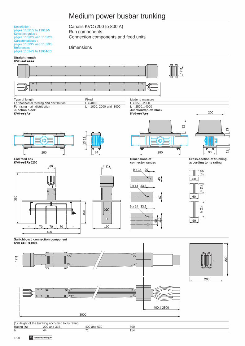
1/30 Te
Medium power busbar trunkingCanalis KVC (200 to 800 A)Run componentsConnection components and feed units
Dimensions
Straight lengthKVC-iiEiiii
Type of length Fixed Made to measureFor horizontal feeding and distribution L = 4000 L = 350...2000For rising main distribution L = 1000, 2000 and 3000 L = 2500…4000Junction block Junction/tap-off blockKV0-iiYAi KV0-iiYAii
End feed box Dimensions of Cross-section of trunkingKV0-iiERi0200 connector ranges according to its rating
Switchboard connection componentKV0-iiERi1004
(1) Height of the trunking according to its ratingRating (A) 200 and 315 400 and 630 800h 44 71 114
Description :pages 11011/2 to 11011/5Selection guide :pages 11012/2 and 11012/3Caractéristiques :pages 11013/2 and 11013/3References :pages 11014/2 to 11014/13
L
h (1
)
h (1
)60
h (1
)
60
h (1
)
6040
209 x 14
67
33,59 x 14
50 110
33,59 x 14
3000
200
200
h (1
)
400 à 2500
84
1313
280 90
200
1313
280
92
h (1)
190
60
= =70 70
400
70
150
350
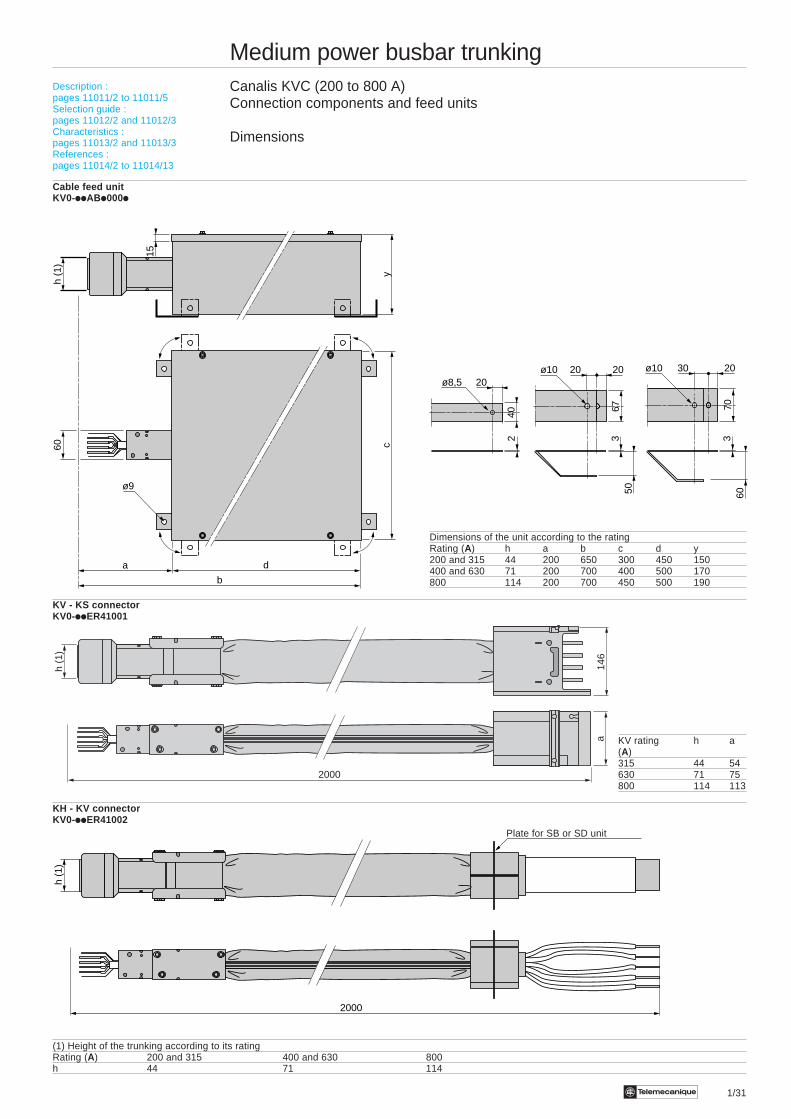
Te 1/31
Medium power busbar trunkingCanalis KVC (200 to 800 A)Connection components and feed units
Dimensions
Cable feed unitKV0-iiABi000i
Dimensions of the unit according to the ratingRating (A) h a b c d y200 and 315 44 200 650 300 450 150400 and 630 71 200 700 400 500 170800 114 200 700 450 500 190
KV - KS connectorKV0-iiER41001
KV rating h a(A)315 44 54630 71 75800 114 113
KH - KV connectorKV0-iiER41002
(1) Height of the trunking according to its ratingRating (A) 200 and 315 400 and 630 800h 44 71 114
Description :pages 11011/2 to 11011/5Selection guide :pages 11012/2 and 11012/3Characteristics :pages 11013/2 and 11013/3References :pages 11014/2 to 11014/13
146
2000
a
h (1
)
240
20ø8,5
6750
20 20ø10
6070
30 20ø10
3 3
2000
h (1
)
Plate for SB or SD unit
b
da
h (1
)60
yc
15
ø9
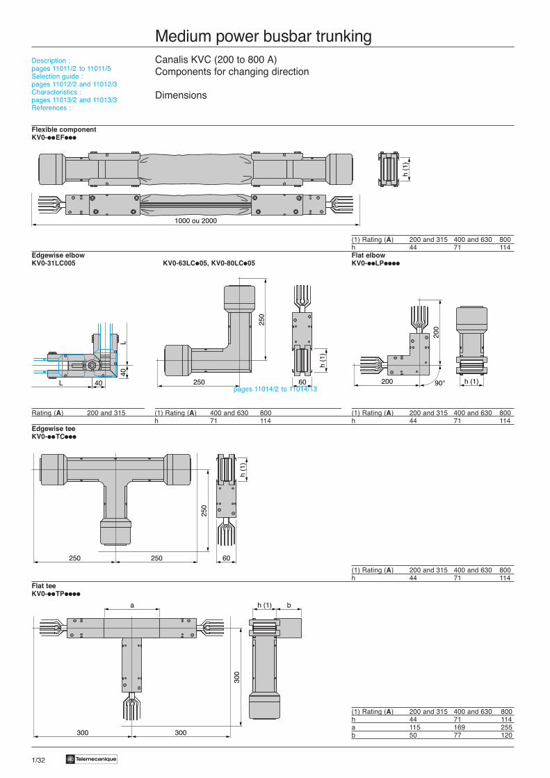

Te 1/33
Medium power busbar trunkingCanalis KVC (200 to 800 A)Tap-off units
Dimensions
Single feeder tap-off unitKV0-iiCB71103
Rating (A) a b c250 525 200 210400 600 300 230Multi-feeder tap-off unitKV0-iiDB06
Rating (A) a b c250 550 600 200400 550 600 200
Description :pages 11011/2 to 11011/5Selection guide :pages 11012/2 and 11012/3Characteristics :pages 11013/2 and 11013/3References :pages 11014/2 to 11014/13
b
a
c
c
b
a
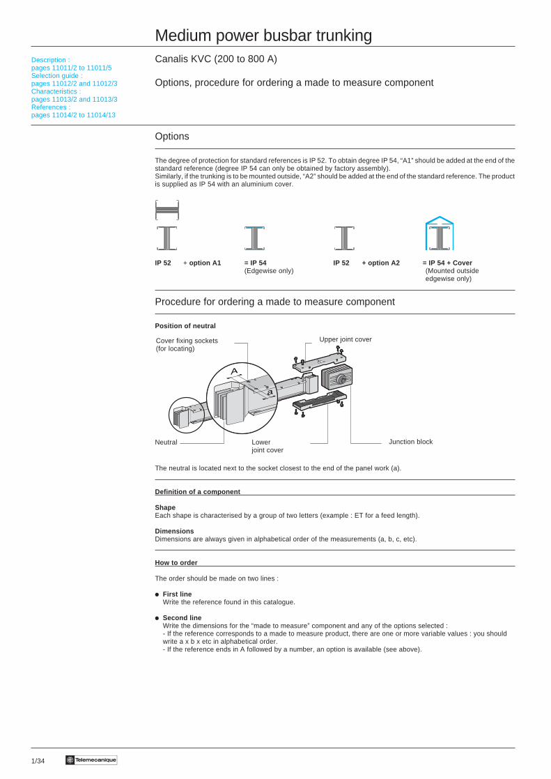
1/34 Te
Medium power busbar trunkingCanalis KVC (200 to 800 A)
Options, procedure for ordering a made to measure component
Options
The degree of protection for standard references is IP 52. To obtain degree IP 54, “A1” should be added at the end of thestandard reference (degree IP 54 can only be obtained by factory assembly).Similarly, if the trunking is to be mounted outside, “A2” should be added at the end of the standard reference. The productis supplied as IP 54 with an aluminium cover.
IP 52 + option A1 = IP 54 IP 52 + option A2 = IP 54 + Cover(Edgewise only) (Mounted outside
edgewise only)
Procedure for ordering a made to measure component
Position of neutral
The neutral is located next to the socket closest to the end of the panel work (a).
Definition of a component
ShapeEach shape is characterised by a group of two letters (example : ET for a feed length).
DimensionsDimensions are always given in alphabetical order of the measurements (a, b, c, etc).
How to order
The order should be made on two lines :
i First lineWrite the reference found in this catalogue.
i Second lineWrite the dimensions for the “made to measure” component and any of the options selected :- If the reference corresponds to a made to measure product, there are one or more variable values : you shouldwrite a x b x etc in alphabetical order.- If the reference ends in A followed by a number, an option is available (see above).
Description :pages 11011/2 to 11011/5Selection guide :pages 11012/2 and 11012/3Characteristics :pages 11013/2 and 11013/3References :pages 11014/2 to 11014/13
a
A
Upper joint cover
Junction blockNeutral Lowerjoint cover
Cover fixing sockets(for locating)
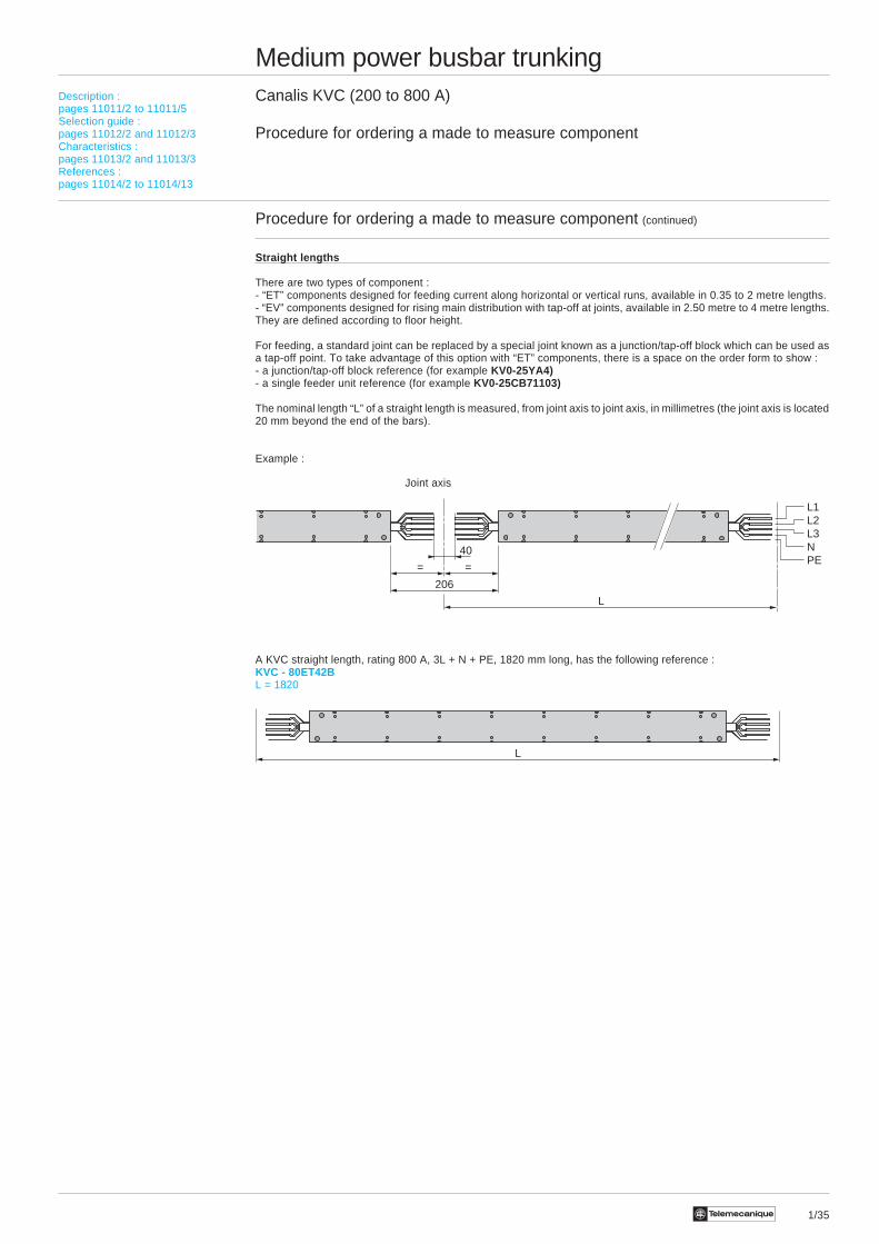
1/35Te
L
40
206
L
==
L1L2L3NPE
Joint axis
Medium power busbar trunkingCanalis KVC (200 to 800 A)
Procedure for ordering a made to measure component
Procedure for ordering a made to measure component (continued)
Straight lengths
There are two types of component :- “ET” components designed for feeding current along horizontal or vertical runs, available in 0.35 to 2 metre lengths.- “EV” components designed for rising main distribution with tap-off at joints, available in 2.50 metre to 4 metre lengths.They are defined according to floor height.
For feeding, a standard joint can be replaced by a special joint known as a junction/tap-off block which can be used asa tap-off point. To take advantage of this option with “ET” components, there is a space on the order form to show :- a junction/tap-off block reference (for example KV0-25YA4)- a single feeder unit reference (for example KV0-25CB71103)
The nominal length “L” of a straight length is measured, from joint axis to joint axis, in millimetres (the joint axis is located20 mm beyond the end of the bars).
Example :
A KVC straight length, rating 800 A, 3L + N + PE, 1820 mm long, has the following reference :KVC - 80ET42BL = 1820
Description :pages 11011/2 to 11011/5Selection guide :pages 11012/2 and 11012/3Characteristics :pages 11013/2 and 11013/3References :pages 11014/2 to 11014/13
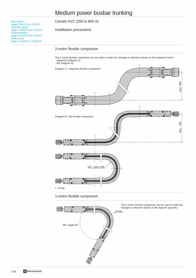
1/36 Te
Medium power busbar trunkingCanalis KVC (200 to 800 A)
Installation precautions
2-metre flexible component
The 2-metre flexible component can be used to make the changes in direction shown on the diagrams below :- edgewise (diagram A)- flat (diagram B)
Diagram A : edgewise flexible component
Diagram B : flat flexible component
1 Fixing
1-metre flexible component
The 1-metre flexible component can be used to make thechanges in direction shown in the diagram opposite.
Description :pages 11011/2 to 11011/5Selection guide :pages 11012/2 and 11012/3Characteristics :pages 11013/2 and 11013/3References :pages 11014/2 to 11014/13
300
700
100
1
1
1
1 1
1
Min. radius
Max
Max
Fixing
Min. angle 60°

1/37Te
Medium power busbar trunkingCanalis KVC (200 to 800 A)
Installation precautions (continued)
Vertical mounting for rising main distribution
If you use floor height lengths (from 2.50 to 4 metres),position the 1st joint at around 1.70 metres above the floor.This operation requires a made to measure component L1.
Description :pages 11011/2 to 11011/5Selection guide :pages 11012/2 and 11012/3Characteristics :pages 11013/2 and 11013/3References :pages 11014/2 to 11014/13
L1 17
00
Level 2
Level 1
Flo
or h
eigh
t


