Model SRX-101ASERVICE MANUAL
KONICA CORPORATIONNo. 26-2, Nishishinjuku 1-chome, Shinjuku-ku, Tokyo 163-0512, Japan
MEDICAL FILM PROCESSOR
CODE NO. 1051/1052

SERVICE MANUAL
SRX-101A Medical Film Processor
Code No. 1051/1052
Contents� Precautions...................................................................................................................................1� Tools and Instrument...................................................................................................................1� Caution Labels .............................................................................................................................21. Specifications...............................................................................................................................42. Dimensions...................................................................................................................................53. Name of Parts...............................................................................................................................64. Time Chart ..................................................................................................................................205. Troubleshooting.........................................................................................................................216. CPU Board DIP Switches ..........................................................................................................467. Checking Circuit Boards Sensors and Electrical Loads........................................................478. Developer Temperature Correction..........................................................................................519. Electrical Components Diagram...............................................................................................5210. Wiring Diagram of Main Unit...................................................................................................5311. Circuit Board Diagram.............................................................................................................5512. Pre-Installation Instructions ...................................................................................................6313. Installation Instructions and Precautions .............................................................................7014. Changing Processing Conditions ..........................................................................................8215. SRX-101A Customer Presentation Guide..............................................................................8316. SRX-101A Light Shield Installation Manual...........................................................................8917. Installation Procedure .............................................................................................................91
PRECAUTIONS
1SERVICE MANUAL
� PRECAUTIONS
Before shipment from the factory, the procedure has already been inspected according to local
safety regulations.
However, the following precautions must be taken when servicing this equipment.
a Before servicing, disconnect the automatic processor's power plug from is AC outlet.
If it is absolutely necessary to repair the processor while the power is on, be sure to take
precautions to avoid electrical shock and keep your fingers away from rollers, gears and
other moving parts.
s Use only the types of fuses specified in this manual.
d Use only the replacement parts specified in this manual.
f When unplugging connectors, disconnect them at the socket. Do not pull on the wire bundle.
g When carrying or shipping circuit boards, place them in static-proof bags, or containers
made of conductive material to prevent damage from static electricity.
h Do not touch the wiring patterns, connector contacts or solder on the circuit boards.
j Take care to prevent washers, bolts or other metal objects from failing into the machine and
causing short circuit or damage to gears. etc.
k Remodeling of processor components or systems which is not described in this operation
manual is forbidden.
l After repairs, make sure all parts and wiring have been correctly replaced and reconnected.
� TOOLS AND INSTRUMENT
In addition to your standard service-use tool kit. the following special tools and equipment will
be necessary.
aPush-pull Gauge (Max. 500g)

2 SERVICE MANUAL
CAUTION LABEL
� Caution labels imply the degree of the risk which may arise from incorrect use of thisproduct.
� There are 3 degrees of caution labels, and each is used depending on the level of riskand damage caused by incorrect use and mishandling.
DANGER : If failed to avoid the risk, this implies the imminent danger level which may lead to serious injury including a loss of life.
WARNING : If failed to avoid the risk, this implies the danger level which may lead to serious injury including a loss of life.
CAUTION : If failed to avoid the risk, this implies the danger level which may lead to moderate damage or light injury. Also it is used when a physical damage alone is expected.
Risk of the damage
High Low
Loss of life or DANGER WARNING
Bodily injuryserious injury
(and damage to property)(Damage is serious)
Moderate damage or WARNING
light injury or CAUTION
(Damage is light) CAUTION
Damage to property only CAUTION
Should this manual become not readable due to any reason,replace it with a new one which is available at charged basis.
1. EXPLANATION OF CAUTION LABELS
� CAUTION LABELS

3SERVICE MANUAL
q
CA
UT
ION
Mak
e su
re th
at th
e in
itial
che
mic
als
are
fille
daf
ter t
he c
ompl
etio
n of
rack
set
ting.
To p
reve
nt c
ross
–con
tam
inat
ion
tilt r
ack
to re
ar o
f pro
cess
orw
hen
rem
ovin
g.If
chem
ical
s ha
ve b
een
fille
d.M
ake
sure
that
che
mic
als
are
not e
xcee
ding
the
indi
cate
leve
l.Ra
ck s
ettin
g sh
ould
be
done
with
car
e so
it d
oes
not c
ause
a s
pill.
Indi
cate
leve
l
1 2
2. W
AR
NIN
G L
AB
EL
S A
ND
TH
EIR
LO
CA
TIO
NS
UL
VO
RS
ICH
TLö
sen
Sie
des
auto
mat
ishe
Bef
ülle
n de
r Tan
ks e
rst a
us,
wenn
die
Rol
lens
ätze
kor
rekt
ein
gese
tzt w
orde
n si
nd.
*Um
ung
ewol
lte C
hem
ikal
ienv
erm
isch
unge
nzw
isch
en d
en B
ädem
zu v
erm
eide
n, n
eige
n Si
e ei
nen
Rolle
nsat
z nac
h hi
nter
n in
Ric
htun
g Ta
nk, w
enn
Sie
ihn
aus
der M
asch
ine
entn
ehm
en w
olle
n.
Eins
etze
n de
r Rol
lens
ätze
in g
efül
lte T
anks
:St
elle
n Si
e si
cher
, daß
der
Fül
lsta
nd in
den
Tan
ks n
icht
den
ang
ezei
gten
.Di
e Ro
llens
ätze
lang
sam
ein
setz
en, o
hne
dies
e fa
llen
zu la
ssen
.
Indi
cate
leve
lM
axim
ulw
ert ü
bers
teig
t
1 2
CA
UT
ION
Mak
e su
re th
at th
e in
itial
che
mic
als
are
fille
daf
ter t
he c
ompl
etio
n of
rack
set
ting.
To p
reve
nt c
ross
–con
tam
inat
ion
tilt r
ack
to re
ar o
f pro
cess
orw
hen
rem
ovin
g.If
chem
ical
s ha
ve b
een
fille
d.M
ake
sure
that
che
mic
als
are
not e
xcee
ding
the
indi
cate
leve
l.Ra
ck s
ettin
g sh
ould
be
done
with
car
e so
it d
oes
not c
ause
a s
pill.
1 2
TÜ
V
w
w
q
t
4 SERVICE MANUAL
SPECIFICATIONS
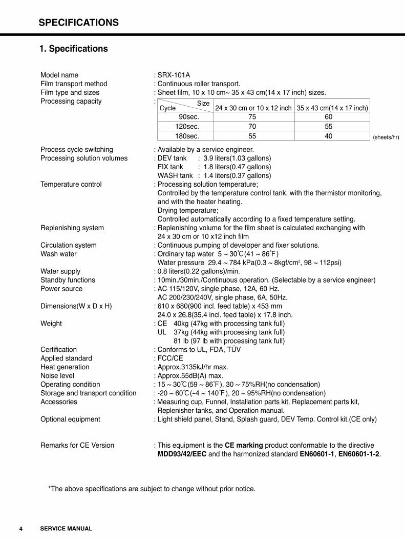
Model name : SRX-101AFilm transport method : Continuous roller transport.Film type and sizes : Sheet film, 10 x 10 cm~ 35 x 43 cm(14 x 17 inch) sizes.Processing capacity :
Process cycle switching : Available by a service engineer.Processing solution volumes : DEV tank : 3.9 liters(1.03 gallons)
FIX tank : 1.8 liters(0.47 gallons)WASH tank : 1.4 liters(0.37 gallons)
Temperature control : Processing solution temperature;Controlled by the temperature control tank, with the thermistor monitoring, and with the heater heating.Drying temperature;Controlled automatically according to a fixed temperature setting.
Replenishing system : Replenishing volume for the film sheet is calculated exchanging with 24 x 30 cm or 10 x12 inch film
Circulation system : Continuous pumping of developer and fixer solutions.Wash water : Ordinary tap water 5 ~ 30:(41 ~ 86<)
Water pressure 29.4 ~ 784 kPa(0.3 ~ 8kgf/cm2, 98 ~ 112psi)Water supply : 0.8 liters(0.22 gallons)/min.Standby functions : 10min./30min./Continuous operation. (Selectable by a service engineer)Power source : AC 115/120V, single phase, 12A, 60 Hz.
AC 200/230/240V, single phase, 6A, 50Hz.Dimensions(W x D x H) : 610 x 680(900 incl. feed table) x 453 mm
24.0 x 26.8(35.4 incl. feed table) x 17.8 inch.Weight : CE 40kg (47kg with processing tank full)
UL 37kg (44kg with processing tank full)81 lb (97 lb with processing tank full)
Certification : Conforms to UL, FDA, TÜVApplied standard : FCC/CEHeat generation : Approx.3135kJ/hr max.Noise level : Approx.55dB(A) max.Operating condition : 15 ~ 30:(59 ~ 86<), 30 ~ 75%RH(no condensation)Storage and transport condition : -20 ~ 60:(--4 ~ 140<), 20 ~ 95%RH(no condensation)Accessories : Measuring cup, Funnel, Installation parts kit, Replacement parts kit,
Replenisher tanks, and Operation manual.Optional equipment : Light shield panel, Stand, Splash guard, DEV Temp. Control kit.(CE only)
Remarks for CE Version : This equipment is the CE marking product conformable to the directive MDD93/42/EEC and the harmonized standard EN60601-1, EN60601-1-2.
*The above specifications are subject to change without prior notice.
SizeCycle 24 x 30 cm or 10 x 12 inch 35 x 43 cm(14 x 17 inch)
90sec. 75 60120sec. 70 55180sec. 55 40 (sheets/hr)
1. Specifications
5SERVICE MANUAL
DIMENSIONS
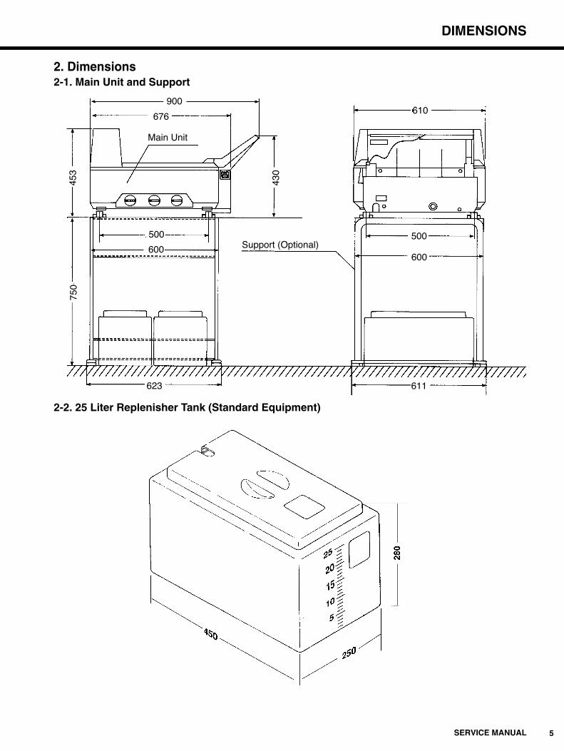
2. Dimensions2-1. Main Unit and Support
2-2. 25 Liter Replenisher Tank (Standard Equipment)
900610
500
600
611
676
500
453
750
430
600
623
Main Unit
Support (Optional)

6 SERVICE MANUAL
NAME OF PARTS
3-2. Main Unit (Left Side View)
™Power Breaker
™Power Cord
™Wash Water Drainage Hose (larger diameter than other hoses)
™Fixer Drainage Hose (red)
™Fixer Supply Hose (red)
™Binding Tape
™Electrical Components Housing
™Developer Supply Hose (yellow)
™Developer Drainage Hose (yellow)
™Overflow Drainage Hose
™Right Side Panel
™Film Exit
™Top Cover
™Level Adjustable Leg
™Control Panel
™Feed Tray
™Feed Tray Cover
™Fixer Drainage Valve ™Developer Drainage Valve
™Water Supply Hose
™Wash Water Drainage Valve
™Left Side Panel
3-1. Main Unit (Front View)
3. Name of Parts

NAME OF PARTS
7SERVICE MANUAL
3-4. Control Panel
3-3. Main Unit (Rear View)
RUNREADY
RUN
™Drier Section Cover
™Back Panel
™RUN LampLights up when the RUN button ispressed. Will automatically go out ifno film has been inserted for 8 hoursafter the READY lamp went on. Willlight up again when the RUN buttonis pressed.
™READY LampLights up when the temperatures ofthe processing chemicals and heaterare at their preset values. Film maybe inserted for processing wheneverthis lamp is on.
™Replenishment ButtonPress and hold down this button forabout 5 seconds to begin the supplyof processing chemicals to the tanksat a rate of 3P per second. Duringreplenishment, READY lamp willchange to flashing.
™RUN ButtonPress this button to start and stopfilm processing.
™RUN Button LampIndicates that the SRX-101A iselectrically powered.
When errors occur, be sure to turn off the power
breaker.(S1)
(Refer to 5. TROUBLESHOOTING page 21.)
8 SERVICE MANUAL
NAME OF PARTS
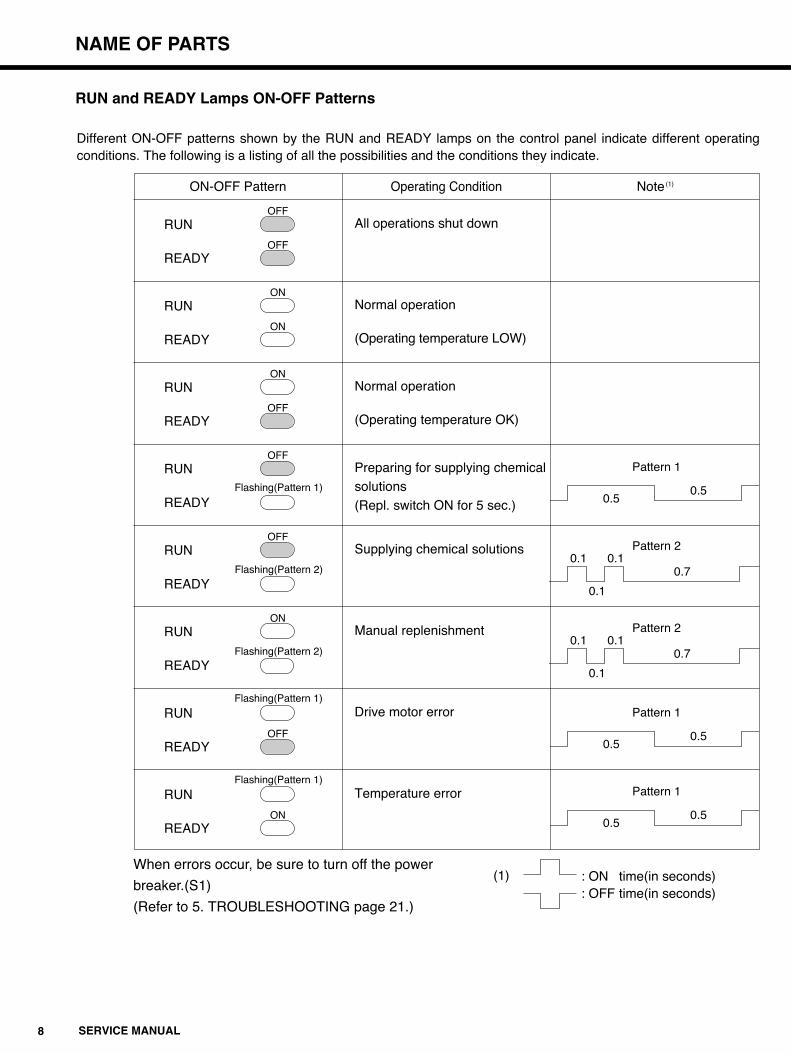
Different ON-OFF patterns shown by the RUN and READY lamps on the control panel indicate different operatingconditions. The following is a listing of all the possibilities and the conditions they indicate.
RUN and READY Lamps ON-OFF Patterns
OFF
OFF
ON
ON
ON
OFF
OFF
Flashing(Pattern 1)
OFF
Flashing(Pattern 2)
ON
Flashing(Pattern 1)
OFF
Flashing(Pattern 1)
ON
RUN
READY
RUN
READY
RUN
READY
RUN
READY
RUN
READY
RUN
READY
RUN
READY
RUN
READY
Flashing(Pattern 2)
ON-OFF Pattern Operating Condition Note(1)
All operations shut down
Normal operation
(Operating temperature LOW)
Normal operation
(Operating temperature OK)
Preparing for supplying chemicalsolutions(Repl. switch ON for 5 sec.)
Supplying chemical solutions
Manual replenishment
Drive motor error
Temperature error
Pattern 1
0.50.5
Pattern 2
0.70.10.1
0.1
Pattern 2
0.70.10.1
0.1
Pattern 1
0.50.5
Pattern 1
0.50.5
: ON time(in seconds): OFF time(in seconds)
(1)
NAME OF PARTS
9SERVICE MANUAL
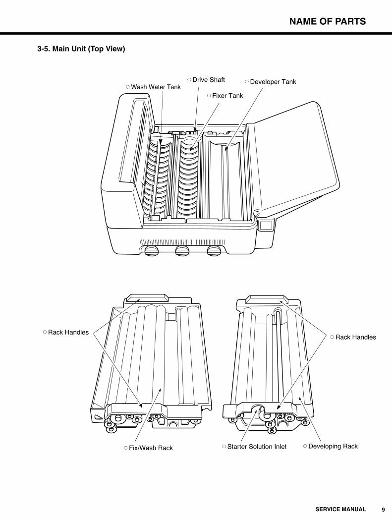
3-5. Main Unit (Top View)
™Wash Water Tank™Drive Shaft
™Fixer Tank
™Developer Tank
™Rack Handles™Rack Handles
™Developing Rack™Starter Solution Inlet™Fix/Wash Rack
10 SERVICE MANUAL
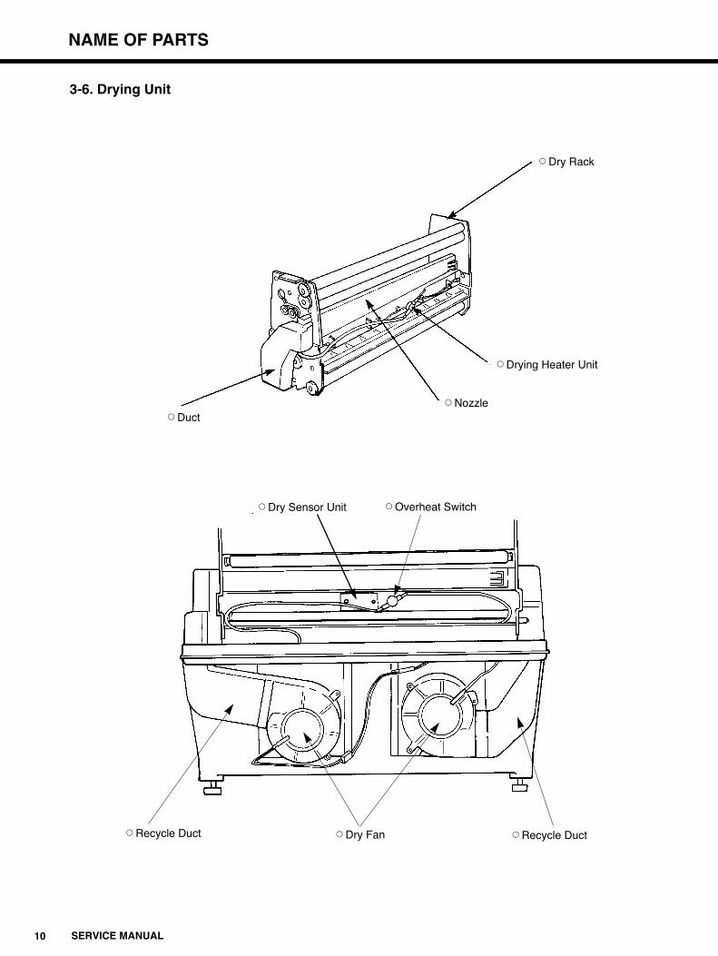
NAME OF PARTS
™Dry Rack
™Drying Heater Unit
™Duct™Nozzle
™Overheat Switch
™Recycle Duct ™Dry Fan ™Recycle Duct
™Dry Sensor Unit
3-6. Drying Unit
NAME OF PARTS
11SERVICE MANUAL
Spr
ings
Typ
eP
arts
No.
L=74
1361
0130
50
L=80
1030
1402
7A
Wor
m G
ear
Par
ts N
o.
Rig
ht10
50-1
3003
A
Left
1050
-130
04A
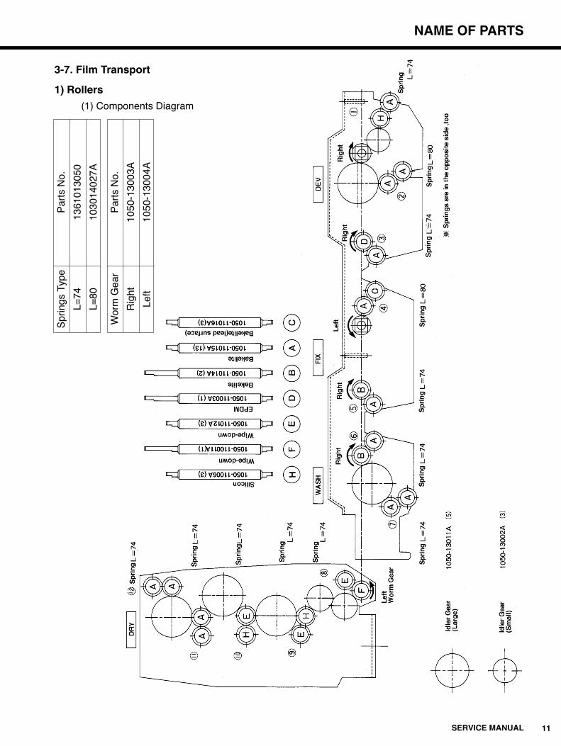
3-7. Film Transport
1) Rollers
(1) Components Diagram

12 SERVICE MANUAL
NAME OF PARTS
(2) Roller Component Listing
NOTE :
In the processing tanks, the "upper" rollers are vertically higher rollers in the solution. In the drying
unit, the "upper" rollers are the rollers closer to the feed tray side of the main unit. the rollers on the
other side are the "lower" rollers.
(3) Capability
The SRX-101A is capable of processing film ranging in size from 10 x 10 cm to 35 x 43cm
(14x17 inch). The feed tray has an insertion slot that will feed film up to 17" in width.
ProcessingUnit
DEV
FIX
WASH
DRY
Upper roller material
Silicon (H)
Bakelite (A)
EPDM (D)
Bakelite (A)
Bakelite (B)
Bakelite (B)
Bakelite (A)
Wipe-down (E)
Silicon (H)
Wipe-down (E)
Bakelite (A)
Bakelite (A)
Lower roller material
Bakelite (A)
Bakelite (A)
Bakelite (A)
Bakelite(lead surface) (C)
Bakelite (A)
Bakelite (B)
Bakelite (A)
Wipe-down (F)
Wipe-down (E)
Silicon (H)
Bakelite (A)
Bakelite (A)
Roller No.
q
w
e
r
t
y
u
i
o
!0
!1
!2
Springlength
74mm
80mm
74mm
80mm
74mm
74mm
74mm
74mm
74mm
74mm
74mm
74mm
Spring pressurein grams
410~480
110~170
410~520
180~270
490~530
450~530
330~530
610~860
590~720
470~620
410~520
460~560
NAME OF PARTS
13SERVICE MANUAL
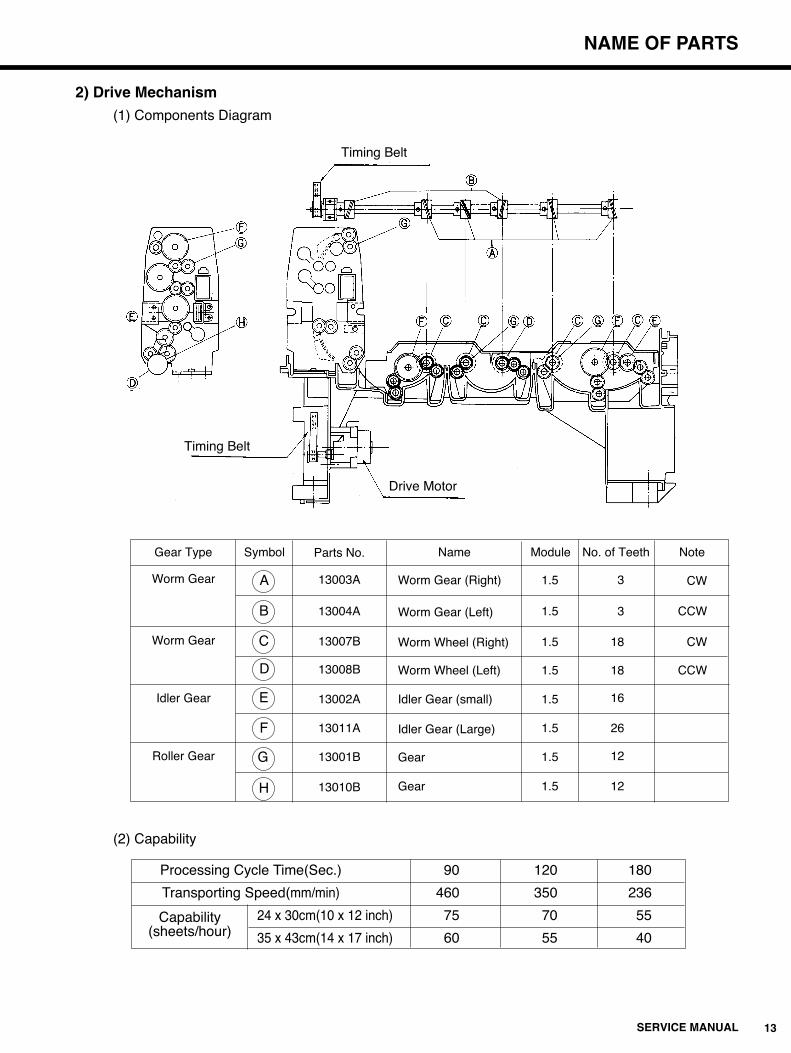
2) Drive Mechanism
(1) Components Diagram
(2) Capability
Timing Belt
Timing Belt
Drive Motor
Gear Type
Worm Gear
Worm Gear
Idler Gear
Roller Gear
Symbol
13003A
13004A
13007B
13008B
13002A
13011A
13001B
13010B
A
B
C
D
E
F
G
H
Parts No. Name
Worm Gear (Right)
Worm Gear (Left)
Worm Wheel (Right)
Worm Wheel (Left)
Idler Gear (small)
Idler Gear (Large)
Gear
Gear
Module
1.5
1.5
1.5
1.5
1.5
1.5
1.5
1.5
No. of Teeth
3
3
18
18
16
26
12
12
Note
CW
CCW
CW
CCW
Processing Cycle Time(Sec.) 90 120 180
Transporting Speed(mm/min) 460 350 236
Capability 24 x 30cm(10 x 12 inch) 75 70 55(sheets/hour) 35 x 43cm(14 x 17 inch) 60 55 40

14 SERVICE MANUAL
NAME OF PARTS
3) Adjusting the Drive Timing Belt
qRemove the Top Cover, the Right Side Panel and the Back Panel.
wTest the tension in the timing belt with a push-pull gauge at a point half way between the main
drive shaft pulley and the drive motor pulley. Adjust the belt tension by loosing the drive motor
and moving it up or down. Proper timing belt tension is in a range between loads of 75 and
125 grams with approximately 2 mm of slack in the belt. Refer to the diagram below.
eWind the rotor located on the back side of the motor mounting 3 times, then check the belt
tension once more to make sure that it is still in a range between loads of 75 and 125 grams
with approximately 2mm of slack in the belt.
rRepeat the same step of (3) eight times. If the tension falls in the above range eight times in a
row, the adjustment has been successfully completed. If even one test result falls that range,
the whole adjustment procedure must be repeated from the beginning.
Main Drive Shaft
Timing Belt
Drive Motor
Drive Motor Pulley
2mm
75~125g
From the rear side of the processor

NAME OF PARTS
15SERVICE MANUAL
1) Components Diagram (Bottom of the Main Unit)
Temperature
Control Tank
Developer
Drainage Valve
Electromagnetic
Valve
Fixer Drainage
Valve
Wash Water
Drainage Valve
Fixer Circulation Pump
Developer Supply Unit
Fixer Supply Unit Developer Circulation Pump
3-8. Solution Supply and Drainage Unit
16 SERVICE MANUAL
NAME OF PARTS
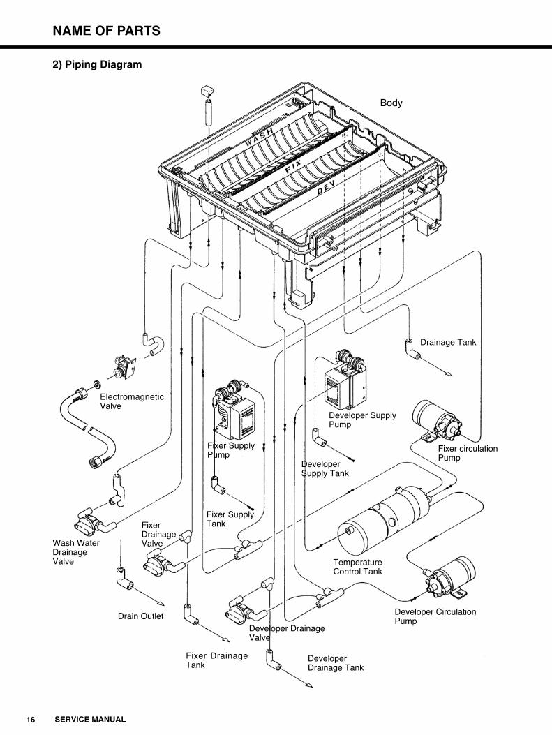
2) Piping Diagram
Body
ElectromagneticValve
Fixer SupplyPump
Developer SupplyPump
Fixer circulationPump
Temperature Control Tank
Developer Circulation Pump
Developer DrainageValve
Wash WaterDrainageValve
Drainage Tank
Fixer SupplyTank
Drain Outlet
Fixer DrainageTank
DeveloperDrainage Tank
DeveloperSupply Tank
Fixer DrainageValve

NAME OF PARTS
17SERVICE MANUAL
3) Solution Temperature Control Tank
(1) Components Diagram
(2) Capabilities
qDeveloper temperature control is carried out by warming with a heater and by natural
cooling.
wFixer temperature is maintained by means of heat transferred from the developer
temperature control tank.
eCirculation volumes :
At 50 Hz : Developer 4.0 liters ; Fixer 4.0 liters/minute
At 60 Hz : Developer 4.8 liters ; Fixer 4.8 liters/minute
rRates of Temperature Rise :
Developer : approx. 1.07:/minute
Fixer : approx. 0.75:/minute
tSensor Precision :
Developer : ±0.5: at settings between 32: and 34:.
From the FixerCirculation Tank
FIX Tank
From the Developer Circulation Pump
Temperature Control Tank
To the DEV Tank
Thermometer
Heater

18 SERVICE MANUAL CE
NAME OF PARTS
Transformer(PT1)
TerminalBlock
Power Breaker (S1)
CPU Board(unified withTemperature Control)
Circuit Protector
CB 1 : 15ACB 3 : 15A
SSR(DEV)
Switching Power source
SSR(DRY)
Noise Filter (F1)
Motor Control Board
3-9. Electrical Components Unit

NAME OF PARTS
18SERVICE MANUAL UL
3-9. Electrical Components Unit
Transformer(PT1)
TerminalBlock
Switching Power Source
Power Breaker (S1)
CPU Board(unified withTemperature Control)
Circuit Protector
CB 1 : 15ASSR(DEV)
SSR(DRY)
Noise Filter (F1)
Motor Control Board

19 SERVICE MANUAL
NAME OF PARTS
※ A rib has been added to the processing tanks so that the Guide has been unified.
Insertion Guide
Moving InsertionDetector
Contact InsertionDetector
Feed Tray
Control Panel Board
3-10. Film Insertion Unit
TIME CHART
20SERVICE MANUAL
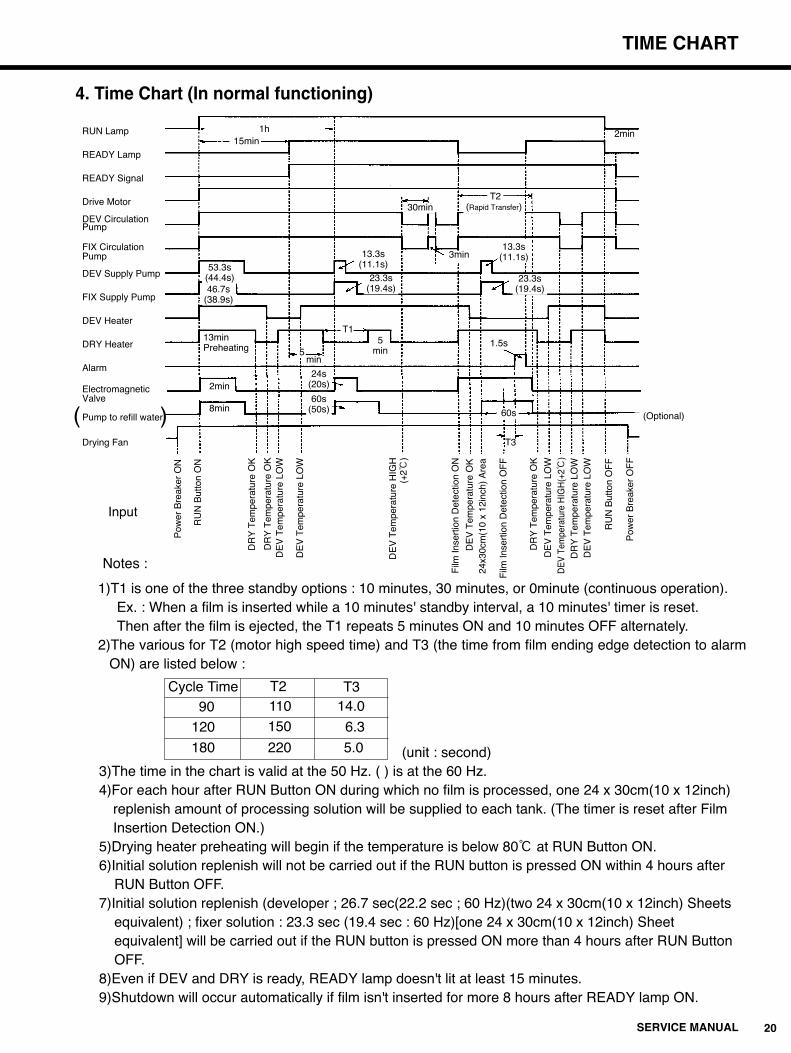
4. Time Chart (In normal functioning)
1)T1 is one of the three standby options : 10 minutes, 30 minutes, or 0minute (continuous operation).Ex. : When a film is inserted while a 10 minutes' standby interval, a 10 minutes' timer is reset. Then after the film is ejected, the T1 repeats 5 minutes ON and 10 minutes OFF alternately.
2)The various for T2 (motor high speed time) and T3 (the time from film ending edge detection to alarmON) are listed below :
(unit : second)3)The time in the chart is valid at the 50 Hz. ( ) is at the 60 Hz.4)For each hour after RUN Button ON during which no film is processed, one 24 x 30cm(10 x 12inch)
replenish amount of processing solution will be supplied to each tank. (The timer is reset after Film Insertion Detection ON.)
5)Drying heater preheating will begin if the temperature is below 80: at RUN Button ON.6)Initial solution replenish will not be carried out if the RUN button is pressed ON within 4 hours after
RUN Button OFF.7)Initial solution replenish (developer ; 26.7 sec(22.2 sec ; 60 Hz)(two 24 x 30cm(10 x 12inch) Sheets
equivalent) ; fixer solution : 23.3 sec (19.4 sec : 60 Hz)[one 24 x 30cm(10 x 12inch) Sheet equivalent] will be carried out if the RUN button is pressed ON more than 4 hours after RUN Button OFF.
8)Even if DEV and DRY is ready, READY lamp doesn't lit at least 15 minutes.9)Shutdown will occur automatically if film isn't inserted for more 8 hours after READY lamp ON.
RUN Lamp
READY Lamp
READY Signal
Drive Motor
DEV CirculationPump
FIX CirculationPump
DEV Supply Pump
FIX Supply Pump
DEV Heater
DRY Heater
Alarm
ElectromagneticValve
Pump to refill water
Drying Fan
Input
1h15min
53.3s(44.4s)46.7s
(38.9s)
13minPreheating
2min
8min
24s(20s)
60s(50s)
min5
5min
1.5s
60s
T3
(Optional)
13.3s(11.1s)
23.3s(19.4s)
13.3s(11.1s)
23.3s(19.4s)
3min
30minT2
(Rapid Transfer)
2min
T1
( )
Notes :
Pow
er B
reak
er O
N
RU
N B
utto
n O
N
DR
Y T
empe
ratu
re O
K
DE
V T
empe
ratu
re L
OW
DR
Y T
empe
ratu
re O
KD
EV
Tem
pera
ture
LO
W
DE
V T
empe
ratu
re H
IGH
(+
2:)
Film
Inse
rtio
n D
etec
tion
ON
DE
V T
empe
ratu
re O
K24
x30c
m(1
0 x
12in
ch)
Are
a
Film
Inse
rtio
n D
etec
tion
OF
F
DR
Y T
empe
ratu
re O
K
DE
V T
empe
ratu
re L
OW
DE
V T
empe
ratu
re H
IGH
(+2:
)D
RY
Tem
pera
ture
LO
WD
EV
Tem
pera
ture
LO
W
RU
N B
utto
n O
FF
Pow
er B
reak
er O
FF
Cycle Time T2110150
220
14.0
6.3
5.0
T390
120
180

21S
ER
VIC
E M
AN
UA
L
TR
OU
BL
E S
HO
OT
ING
5. TROUBLESHOOTING5-1. Motor and Preset Temperature ErrorsIn this SRX-101A, the motor error or the Temperature error will be indicated by the control panel lamps and an alarm buzzer. When such errorsoccur, use the following listing to correct these errors. The other errors will not displayed, so these errors have to be dealt with in the nextsections. (When errors occur, be sure to turn off the power source (S1))
Error
Motor
Temperatures
Display
The RUN lamp will beginflashing, the READY lampwill go out, and the alarm willsound.
The RUN lamp will beginflashing, the READY lampwill remain lit, and the alarmwill sound.
Cause
The rack drive motor isbeing overloaded.
The temperature levelsfor the developer and/orheater have dangerouslyrisen above the presetvalues, or have remainedbelow these values for along period of time.
Response
q Check to see if there is film or some foreign object jammed in the rack rollers or gear mechanisms.
w The rack rollers and gears may not be rotating smoothly due to shaft supports worn down by built up processing solution crystals.
e Is the drive motor damaged?r Is AC 24V±10% being
supplied to the motor control board?
Reset or Set Direction
Setq The range of motor cycle is over 10% (LOK signal ON) for three
seconds.w When the over 0.83N.m torque is on the motor shaft.
ResetWhen the power source is OFF.
Set ¡About the developer temperature.q Although 45 minutes has passed after the RUN Button is on, the dev. temp.
does not reach set value.w When the dev. temp. is over ±3: of the range of preset value for 3 minutes
after the Ready Lamp is on.¡About the dry temperature.q Although 45 minutes has passed after the Run Button is on, the condition is
not ready.w When the dry temp. is lower than 210: although 25 minutes has passed
after it is over 210:.(Once it is over 250:, the 25 min. timer is canceled.)e After the Run Button is on, the over 270: keeps for 3 minutes.r While Ready lamp is on and film is processed, over ±20: of the preset
value keeps for 3 minutes.t While Ready lamp is on and film is not processed, 160:±20: keeps for 3
minutes.ResetWhen the power source is off.
q Check to see if the developer is being circulated properly.
w Is the heater fan ON and functioning properly?
e Is the room temperature around the processor exceeding 30:?
r Check the developer and dry heater wiring damage.
t Check for breaks in the connection the developer and dry sensor to the temperature control board.
y Is there film jammed in the drying unit?
RUNREADY
RUN
Flashing ON
READY
Flashing OFF
RUN
RUN

TROUBLE SHOOTING
22SERVICE MANUAL
5-2. TROUBLESHOOTING : FLOW CHARTS
No. Problem Page
1 Processor will not start up (RUN lamp will not come on) 23
2 Developer circulation pump not operating. 24
3 Fixer circulation pump not operating. 25
4 Drying fans not operating. 26
5 Electromagnetic valve not operating. 27
6 Developer supply pimp not operating. 28
7 Fixer supply pump not operating. 29
8 Drive motor not operating. 30
9 Drive motor will not shut off. 31
10 Developer temperature too low. 32
11 Developer temperature too high. 33
12 Drying temperature too low. 34
13 Drying temperature too high. 35
14 Supply pumps will not respond to electrical cycle change. 36
15 Initial or replenish solution supply not operating properly. 36
16 Supply pumps will not shut OFF. 36
17 READY light will not come ON. 37
18 READY light will not turn OFF. 37
19 Film insertion alarm will not sound. 38
20 Film insertion alarm will not turn OFF. 38
21 Processor will not switch over to the Standby Mode. 39
22 Processor will not switch out of the Standby Mode. 39
23 SERVICE MANUAL
TROUBLE SHOOTING
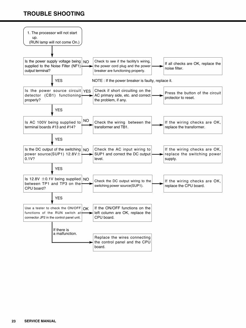
1. The processor will not start up.
(RUN lamp will not come On.)
Is the power supply voltage beingsupplied to the Noise Filter (NF1)output terminal?
Is the power source circuitdetector (CB1) functioningproperly?
Is AC 100V being supplied toterminal boards #13 and #14?
Is the DC output of the switchingpower source(SUP1) 12.8V±0.1V?
Is 12.8V ±0.1V being suppliedbetween TP1 and TP3 on theCPU board?
Use a tester to check the ON/OFF
functions of the RUN switch at
connector JP2 in the control panel unit.
Check to see if the facility's wiring,the power cord plug and the powerbreaker are functioning properly.
Check if short circuiting on theAC primary side, etc. and correctthe problem, if any.
Check the wiring between thetransformer and TB1.
Check the AC input wiring toSUP1 and correct the DC outputlevel.
Check the DC output wiring to theswitching power source(SUP1).
If the ON/OFF functions on theleft column are OK, replace theCPU board.
Replace the wires connectingthe control panel and the CPUboard.
If all checks are OK, replace thenoise filter.
Press the button of the circuitprotector to reset.
If the wiring checks are OK,replace the transformer.
If the wiring checks are OK,replace the switching powersupply.
If the wiring checks are OK,replace the CPU board.
YES
YES
YES
YES
YES
If there is a malfunction.
NO
YES
NO
NO
NO
NOTE : If the power breaker is faulty, replace it.
OK

TROUBLE SHOOTING
24SERVICE MANUAL
2.The developer circulation pump (P1) is mot operating.
Are the other electrical loadsfunctioning properly?
Is the CPU board fuse (F1)blown?
Is AC 100V being supplied toterminal board TB1 terminals#13 and #14?
Is Ac 100V being supplied toJP12?
Is AC 100V being supplied toJP11?
Check the wires connecting thedeveloper circulation pump(P1) toJP11.
Check the connection to connectorJJ11 and the terminal voltage.
Replace the fuse on the CPUboard(F1).
Check the wiring from thetransformer to TB1.
Check the wiring connectingJP12 to TB1.
Check the wiring connectingJP12 to the CPU board.
Repair any wiring breaks orreplace the circulation pump.
If all checks are OK, repair anywiring breaks and/or replace thepump.
If all checks are OK, repair anywiring breaks and/or replace thetransformer.
Repair any wiring breaks orreplace the wiring.
If all checks are OK, replace theCPU board.
NO
NO
YES
YES
YES
YES
YES
NO
NO
NO
25 SERVICE MANUAL
TROUBLE SHOOTING
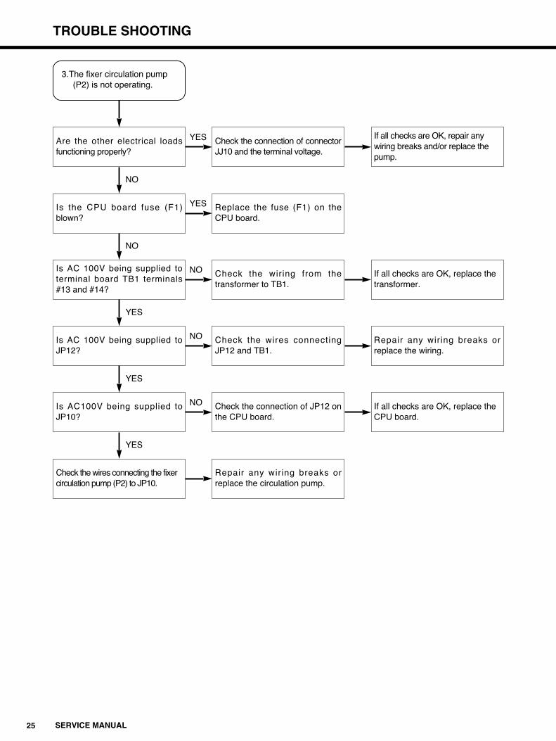
3.The fixer circulation pump (P2) is not operating.
Are the other electrical loadsfunctioning properly?
Is the CPU board fuse (F1)blown?
Is AC 100V being supplied toterminal board TB1 terminals#13 and #14?
Is AC 100V being supplied toJP12?
Is AC100V being supplied toJP10?
Check the wires connecting the fixer circulation pump (P2) to JP10.
Check the connection of connectorJJ10 and the terminal voltage.
Replace the fuse (F1) on theCPU board.
Check the wiring from thetransformer to TB1.
Check the wires connectingJP12 and TB1.
Check the connection of JP12 onthe CPU board.
Repair any wiring breaks orreplace the circulation pump.
If all checks are OK, repair any wiring breaks and/or replace the pump.
If all checks are OK, replace the transformer.
Repair any wiring breaks orreplace the wiring.
If all checks are OK, replace the CPU board.
NO
NO
YES
YES
YES
YES
YES
NO
NO
NO

TROUBLE SHOOTING
26SERVICE MANUAL
4. The drying fans (FM1,FM2)are not operating.
Are the other electrical loads functioning properly?
Is AC100V being supplied toterminal board TB1 terminals#13 and #14?
Check the wires connectingterminal board TB1 and the fans.
Check the connection at connectors JJ11 and check the terminal voltage.
Check the wiring from thetransformer to TB1.
Repair any breaks or replace thefans.
If all checks are OK, repair anywiring breaks or replace the fans.
If all checks are OK, repair any wiring and/or replace the transformer.
NO
YES
YES
NO

27 SERVICE MANUAL
TROUBLE SHOOTING
5. The electromagnetic valve (MV) is not operating.
Are the other electrical loads functioning properly?
Is the CPU board fuse (F1) blown?
Is AC 100V being supplied to terminal board TB1 terminals #13 and #14?
Is AC 100V being supplied to JP12?
Is AC100V being supplied to JP6?
Is AC100V being supplied atboth fastened terminal of theElectromagnetic valve?
Check the connection at connectorJJ6 and the terminal voltage.
Replace the fuse (F1) on the CPU board.
Check the wiring from the transformer to TB1.
Check the wires connecting JP12 and TB1.
Check the wiring connecting JP6and the CPU board
Repair any wiring breaks.
If all checks are OK, repair any wiring breaks and/or replace the valve.
If all checks are OK, repair any wiring breaks and/or replace the transformer.
Repair any wiring breaks orreplace the wiring.
If all checks are OK, replace the CPU board.
NO
NO
YES
YES
YES
Replace the Electromagneticvalve.
YES
YES
YES
NO
NO
NO
TROUBLE SHOOTING
28SERVICE MANUAL
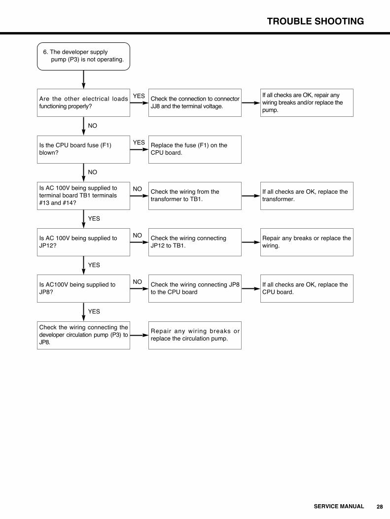
6. The developer supply pump (P3) is not operating.
Are the other electrical loadsfunctioning properly?
Is the CPU board fuse (F1) blown?
Is AC 100V being supplied to terminal board TB1 terminals #13 and #14?
Is AC 100V being supplied to JP12?
Is AC100V being supplied to JP8?
Check the wiring connecting thedeveloper circulation pump (P3) toJP8.
Check the connection to connectorJJ8 and the terminal voltage.
Replace the fuse (F1) on the CPU board.
Check the wiring from the transformer to TB1.
Check the wiring connecting JP12 to TB1.
Check the wiring connecting JP8to the CPU board
Repair any wiring breaks orreplace the circulation pump.
If all checks are OK, repair any wiring breaks and/or replace the pump.
If all checks are OK, replace the transformer.
Repair any breaks or replace thewiring.
If all checks are OK, replace the CPU board.
NO
NO
YES
YES
YES
YES
YES
NO
NO
NO
29 SERVICE MANUAL
TROUBLE SHOOTING
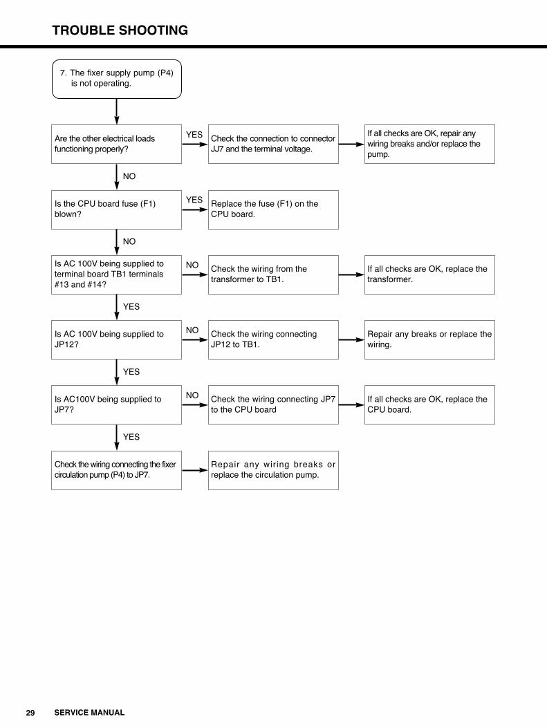
7. The fixer supply pump (P4)is not operating.
Are the other electrical loads functioning properly?
Is the CPU board fuse (F1) blown?
Is AC 100V being supplied to terminal board TB1 terminals #13 and #14?
Is AC 100V being supplied to JP12?
Is AC100V being supplied to JP7?
Check the wiring connecting the fixer circulation pump (P4) to JP7.
Check the connection to connectorJJ7 and the terminal voltage.
Replace the fuse (F1) on the CPU board.
Check the wiring from the transformer to TB1.
Check the wiring connecting JP12 to TB1.
Check the wiring connecting JP7to the CPU board
Repair any wiring breaks orreplace the circulation pump.
If all checks are OK, repair any wiring breaks and/or replace the pump.
If all checks are OK, replace the transformer.
Repair any breaks or replace thewiring.
If all checks are OK, replace the CPU board.
NO
NO
YES
YES
YES
YES
YES
NO
NO
NO
TROUBLE SHOOTING
30SERVICE MANUAL
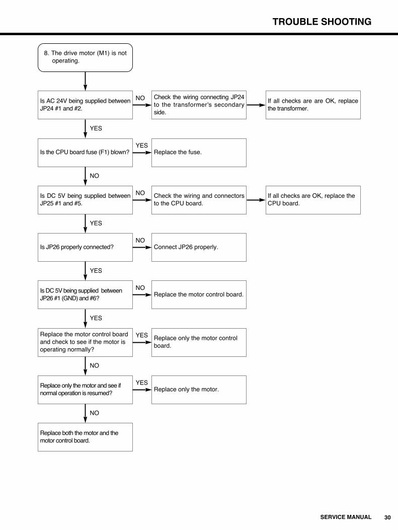
8. The drive motor (M1) is notoperating.
Is AC 24V being supplied betweenJP24 #1 and #2.
Is the CPU board fuse (F1) blown?
Is DC 5V being supplied betweenJP25 #1 and #5.
Is JP26 properly connected?
Is DC 5V being supplied between JP26 #1 (GND) and #6?
Replace the motor control board and check to see if the motor is operating normally?
Check the wiring connecting JP24to the transformer's secondaryside.
Replace the fuse.
Check the wiring and connectorsto the CPU board.
Connect JP26 properly.
Replace the motor control board.
Replace only the motor control board.
If all checks are are OK, replacethe transformer.
If all checks are OK, replace the CPU board.
YES
NO
YES
YES
YES
NO
YES
NO
NO
NO
Replace only the motor and see if normal operation is resumed?
Replace only the motor.
NO
YES
Replace both the motor and the motor control board.
NO
YES

31 SERVICE MANUAL
TROUBLE SHOOTING
9. The drive motor (M1) will not stop.
Did you wait for 2 minutes afterpressing the RUN switch OFF?
Is at least 4.3V being supplied totest pin TO8 on the CPU board?
Replace the motor drive, and see ifthe drive motor stop.
If it does not stop, replace the drivemotor.
Wait for the required time.
Check to see if the output voltage of the switching power source is 12.8V±0.1V.
If the operation is normal, use themotor drive board which has beenreplaced.
NOTE : Refer to the procedure for temperature control board adjustments.
If all checks are OK, replacethe CPU board.
YES
YES
NO
NO
YES

TROUBLE SHOOTING
32SERVICE MANUAL
10. Developer temperature is too low.
Is the temperature setting too low?
Is the overheat switch conducting electricity?
Is DC 5V being supplied betweenSSR1 #3 and #4?
Is electricity being conducted between SSR1 #1 and #2?
Is AC 100V being supplied between #2 and #3 on terminal board TB1?
Is AC 100V being supplied between #1 and #5 on terminal board TB1?
Adjust the temperature setting using the temperature control volume.
After temperature setting adjustment, if improper temperature levels activates the temperature error function, all the electrical loads will be switched OFF.
Replace the overheat switch.
Check if the sensors and temperature control circuits on CPU board are functioning properly?
Replace SSR1.
Check the wiring connecting TB1to Developer heater.
Check the wiring connecting TB1to SSR1.
(See the circuit board check procedures.)
If all of the checks are OK, checkthe wiring connecting the CPU board to SSR, and repair the anywiring breaks.
If it is not OK, adjust or replace the CPU board.
If all of the checks are OK, replace a temperature control tank.
Replace any faulty parts.
NO
YES
YES
YES
NO
YES
NO
NO
NO
YES
Check the wiring to the power breaker and noise filter.
Repair any wiring breaks andreplace any faulty parts.
NO
YES
(See the CPU board check procedures.)
NOTE :

33 SERVICE MANUAL
TROUBLE SHOOTING
If all of the checks are OK, checkthe wiring connecting the CPU board to SSR, and repair the any wiring breaks.
If it is not OK, adjust or replace the CPU board.
11. Developer temperature is too high.
Is the temperature setting too high?
Is DC 5V being supplied betweenSSR1 #3 and #4?
Is electricity being conducted between SSR1 #1 and #2?
Is AC 100V being supplied between #2 and #3 on terminal board TB1?
Check the wiring between TB1 and SSR1.
Adjust the temperature settingusing the temperature controlboard volume.
After temperature setting adjustment, if improper temperature levels activates the temperature error function, all the electrical loads will be switched OFF.
Check if the sensors and temperature control circuits onCPU board are functioningproperly?
Replace SSR1.
Check the wiring connecting TB1to Developer heater.
Repair any wiring breaks andreplace any faulty parts.
(See the circuit board check procedures.)
If all of the checks are OK, replace the temperature control tank.
NO
NO
NO
NO
YES
YES
YES
YES
(See the temperature control board check procedures.)
NOTE :

TROUBLE SHOOTING
34SERVICE MANUAL
12. Drying temperature is too low.
Is the temperature setting too low?
Is the overheat switch conducting electricity?
Is DC 5V being supplied between SSR2 #3 and #4?
Is electricity being conducted between SSR2 #1 and #2?
Is AC 100V being supplied between #1 and #4 on terminal board TB1?
Is AC 100V being supplied between #1 and #5 on terminal board TB1?
Adjust the temperature settingusing the temperature controlvolume.
After temperature setting adjustment, if improper temperature levels activates the temperature error function, all the electrical loads will be switched OFF.
Replace the heater unit.
Check if the sensors and temperature control circuits onCPU board are functioningproperly?
Replace SSR2.
Check the wiring connecting TB1to Developer heater.
Check the wiring connecting TB1to SSR2.
(See the circuit board check procedures.)
If all of the checks are OK, checkthe wiring connecting the CPUboard to SSR, and repair the anywiring breaks.
If it is not OK, adjust or replace the CPU board.
If all of the checks are OK, replace the temperature control tank.
Repair or replace any faulty parts.
NO
YES
YES
YES
NO
YES
NO
NO
NO
YES
Check the wiring to the power breaker and the noise filter.
Replace any faulty parts.
NO
YES
See temperature control check procedure.
NOTE :

35 SERVICE MANUAL
TROUBLE SHOOTING
If all of the checks are OK, checkthe wiring connecting the CPUboard to SSR, and repair the anywiring breaks.
If it is not OK, adjust or replace the CPU board.
13. Drying temperature is too high.
Is the temperature setting too high?
Is DC 5V being supplied between SSR2 #3 and #4?
Is electricity being conducted between SSR2 #1 and #2?
Is AC 100V being supplied between #1 and #4 on terminal board TB1?
Check the wiring between TB1 and SSR2.
Adjust the temperature settingusing the temperature controlboard volume.
After temperature setting adjustment, if improper temperature levels activates the temperature error function, all the electrical loads will be switched OFF.
Check if the sensors and temperature control circuits onCPU board are functioningproperly?
Replace SSR2.
Check the wiring connecting TB1to Developer heater.
Repair any wiring breaks andreplace any faulty parts.
(See temperature control board adjustment procedures)
If all of the checks are OK, replace the temperature control tank.
NO
NO
NO
NO
YES
YES
YES
YES
(See the temperature control board check procedures.)
NOTE :

TROUBLE SHOOTING
36SERVICE MANUAL
14. Supply pumps (P3, P4) will not respond to frequency (DIPSW 1-2) setting change.
Is DIP SW1-2 in the ON position?
Replace the CPU board.
Set DIPSW1-2 to ON.
YES
NO
16. Supply pumps (P3,P4) willnot stop.
Is the film entry detector ON (READY lamp OFF)?
Replace the CPU board.
Check if there is any film jammed at the detector or not.
REMINDER:Initial/replenish solution supply may require the supply pumps to operate for several ten minutes.
If all of the checks are OK, replace the film entry detector unit.
NO
YES
15. Initial or replenish solutionsupply not operating properly.
Replace the CPU board.REMINDER :Be aware that initial solution supply may not be carried out due to the timing of RUN switch ON.
NOTE: Initial supply is the amount of solution supplied immediately after the RUN switch is pressed ON. Replenish supply is the amount of solution if no film has been processed over an hour's duration.
REMINDER : In case of 50Hz, "in the OFF position."
37 SERVICE MANUAL
TROUBLE SHOOTING
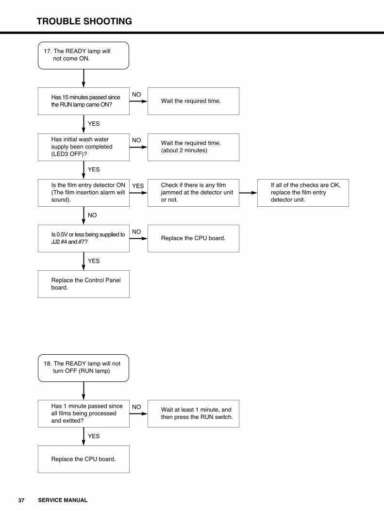
17. The READY lamp will not come ON.
Has 15 minutes passed since the RUN lamp came ON?
Has initial wash water supply been completed (LED3 OFF)?
Wait the required time.
YES
NO
Is the film entry detector ON (The film insertion alarm will sound).
Wait the required time.(about 2 minutes)
YES
NO
Is 0.5V or less being supplied to JJ2 #4 and #7?
Check if there is any film jammed at the detector unit or not.
If all of the checks are OK, replace the film entry detector unit.
NO
YES
Replace the Control Panel board.
Replace the CPU board.
YES
NO
18. The READY lamp will not turn OFF (RUN lamp)
Has 1 minute passed since all films being processed and exitted?
Replace the CPU board.
Wait at least 1 minute, and then press the RUN switch.
YES
NO

TROUBLE SHOOTING
38SERVICE MANUAL
19. The film insertion alarm will not sound.
Is the film entry detector ON (READY lamp OFF)?
Replace the CPU board.
Check if there is any film jammed at the detector unit.
If all of the checks are OK, replace the film entry detector unit.
NO
YES
20. Film insertion alarm will not turn OFF.
Replace the CPU board.REMINDER :The alarm sounds intermittently whenever an error occurs.
39 SERVICE MANUAL
TROUBLE SHOOTING
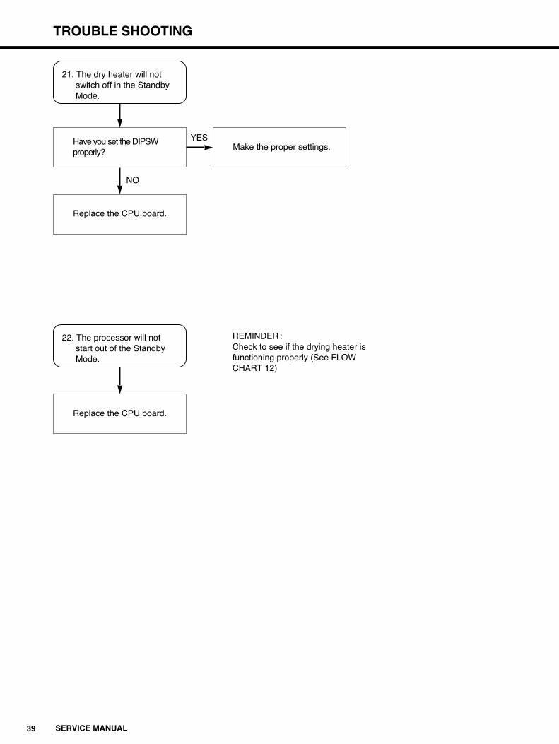
21. The dry heater will not switch off in the Standby Mode.
Have you set the DIPSW properly?
Replace the CPU board.
Make the proper settings.
NO
YES
22. The processor will not start out of the Standby Mode.
Replace the CPU board.
REMINDER:Check to see if the drying heater is functioning properly (See FLOW CHART 12)
TROUBLE SHOOTING
40SERVICE MANUAL
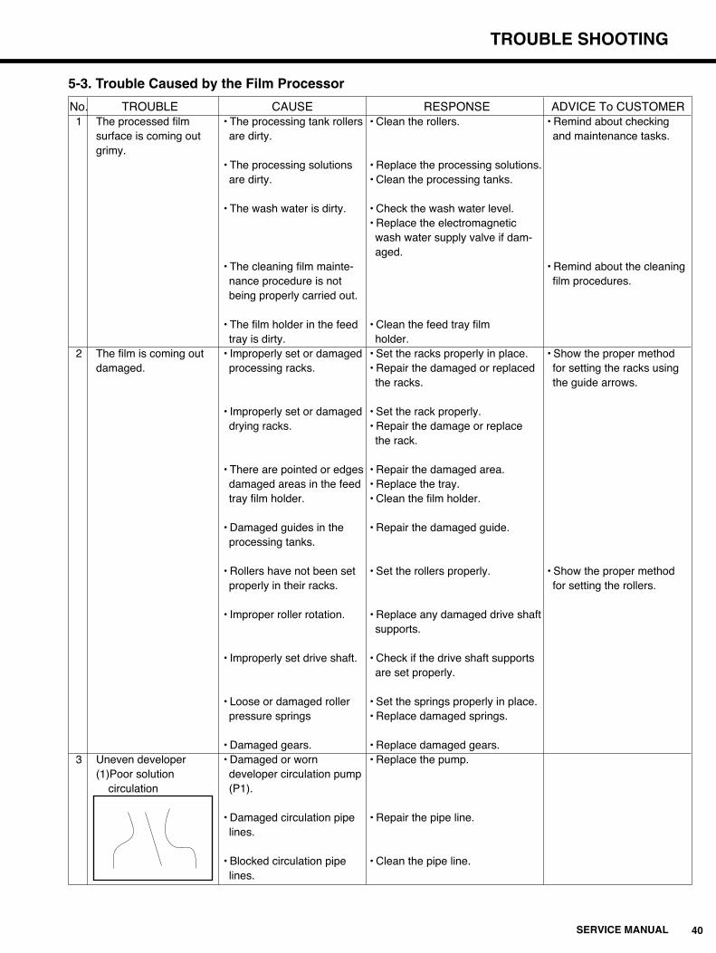
5-3. Trouble Caused by the Film Processor
No. TROUBLE CAUSE RESPONSE ADVICE To CUSTOMER1 The processed film • The processing tank rollers • Clean the rollers. • Remind about checking
surface is coming out are dirty. and maintenance tasks.grimy.
• The processing solutions • Replace the processing solutions.are dirty. • Clean the processing tanks.
• The wash water is dirty. • Check the wash water level.• Replace the electromagneticwash water supply valve if dam-aged.
• The cleaning film mainte- • Remind about the cleaningnance procedure is not film procedures.being properly carried out.
• The film holder in the feed • Clean the feed tray filmtray is dirty. holder.
2 The film is coming out • Improperly set or damaged • Set the racks properly in place. • Show the proper methoddamaged. processing racks. • Repair the damaged or replaced for setting the racks using
the racks. the guide arrows.
• Improperly set or damaged • Set the rack properly.drying racks. • Repair the damage or replace
the rack.
• There are pointed or edges • Repair the damaged area.damaged areas in the feed • Replace the tray.tray film holder. • Clean the film holder.
• Damaged guides in the • Repair the damaged guide.processing tanks.
• Rollers have not been set • Set the rollers properly. • Show the proper methodproperly in their racks. for setting the rollers.
• Improper roller rotation. • Replace any damaged drive shaftsupports.
• Improperly set drive shaft. • Check if the drive shaft supportsare set properly.
• Loose or damaged roller • Set the springs properly in place.pressure springs • Replace damaged springs.
• Damaged gears. • Replace damaged gears.3 Uneven developer • Damaged or worn • Replace the pump.
(1)Poor solution developer circulation pumpcirculation (P1).
• Damaged circulation pipe • Repair the pipe line.lines.
• Blocked circulation pipe • Clean the pipe line.lines.

41 SERVICE MANUAL
TROUBLE SHOOTING
No. PROBLEM CAUSE RESPONSE ADVICE To CUSTOMER(2)Bands across the film • Improper roller rotation. • Check the film transport • Remind about the periodical
perpendicular to the mechanism. check and maintenance.direction of film transport. • Dirty rubber rollers. • Clean the rollers. • Show the proper method
for setting the rollers.
• Film slippage in the rollers. • Make sure all of the moving parts • Show the proper method are set properly. for setting the racks using
• Replace all damaged parts. the guide arrows.
(3)Black streaks • Improper roller rotation. • Check the film transport • Remind about the periodicalmechanism. check and maintenance.
• Dirty rubber rollers. • Clean the rollers. • Show the proper methodfor setting the rollers.
• Film slippage in the rollers. • Make sure all of the moving parts • Show the proper methodare set properly. for setting the racks using
• Replace all damaged parts. the guide arrows.
(4)Pressure marks • Developing rack roller • Replace any faulty rollers. • Remind about when thesurface is too rough. rollers should be cleaned.
• Developing rack roller • Clean the rollers. • Show the proper methodsurface is dirty. for cleaning the rollers.
4 Poor film developing • Insufficient solution • Replace the faulty parts.(Poor density) replenishing.
Faulty supply pump (P3).Faulty supply line.
• The developer is exhausted • Replace the developer solution. • Remind about processingdue to overuse. solution replacement
intervals.• Incorrect developer • Correct the developer temperature. temperature setting.
5 Poor fixing quality • Insufficient replenishing • Replace the faulty parts.Faulty supply pump (P4)Faulty supply line
• The fixer is exhausted • Replace the fixer solution. • Remind about processingdue to over use. solution replacement(When processing small film intervals.lots.)
• The fixer temperature is • Show the proper methodtoo low. for maintaining optimum
fixer temperature.

TROUBLE SHOOTING
42SERVICE MANUAL
No. TROUBLE CAUSE RESPONSE ADVICE To CUSTOMER6 Discoloration • The fixer solution temperature • Show the proper method for
is too low. maintaining optimum fixer temperature.
• The wash water temperature • Install a water heating device.is too low.
• The fixer is exhausted due to • Replace the fixer • Remind about processing solutionoveruse. (when processing solution. replacement intervals.small film lots.)
• There is no water in the • Replace the faulty • Show checking method of the water WASH Water tank. parts. supply valve and wash water drainage
valve.7 Insufficient drying • Incorrect temperature setting. • Correct the temperature
setting.The drying heater (H1) is • Replace the faulty parts.faulty.The drying heater fans (FM1,2)are faulty.The drying sensor (RB1)is faulty.
8 Uneven drying • Incorrect temperature setting. • Correct the temperaturesetting.
The drying heater (H1) is • Replace the faulty parts.faulty.The drying heater fans (FM1,2)are faulty.The drying sensor (RB1) isfaulty.
• Clean or replace• The wipe-down roller is dirty. the wipe-down roller.

43 SERVICE MANUAL
TROUBLE SHOOTING
5-4. Trouble Caused by Improper Film Handling
PROBLEM SYMPTOM CAUSE RESPONSEFogging • A certain portion of the film is • Improper light shielding of • Checking and repair.
being blackened. stored film (due to torn (This is occurring in the same wrapping), a film casette spot on a large number and the other facilities.of sheets.)
• Gas fogging due to sulfurousgas,etc. when docked with otherequipment.
• Circular density unevenness. • Fogging due to light from • Adjust the photoelectric detection the photoelectric sensors. system.
• Radiation material is attachedto the film packaging.
• Traces or shadows of objects • Improper light shielding. • Checking and repair.have been transferred ontothe film.
• Fogging due to long term • Use a safety light that is compatibleexposure to a safety light with the film and strictly follow allwhose intensity is not suited precautions for its use.to the level of film sensitivity.
• Fogging by radiation. • Properly shield the equipment fromradiation.
• Fogging damage to every sheet • The film is being stored under • Store the film in a well air conditionedof film being processed. excessive temperature or and ventilated facilities.
humidity condition.
• Fogging due to gas from • Check the room air exhaust conditions.painted surface in the film storage facilities.
• Safelight fogging.
• The film has been past over • Use film based on a consuming plan.the expiration date.
Static • Certain patterns shaped like • The film is being exposed byelectricity a branch, dot or clouded are a source of static electricity.marking on the film.
• The temperature around the • Use a humidifier to correct dry, lowprocessor is too low. humidity conditions around
the processor.
• Film sensitive to electricalcharge is being used.
• The film is being affectedby friction during handling.
• The equipment is being • Use anti-static cleaners.electrically charged.
• The screen is being electricallycharged.
TROUBLE SHOOTING
44SERVICE MANUAL
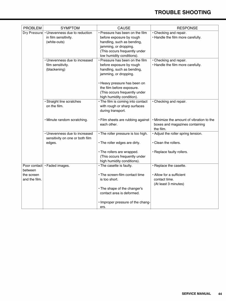
PROBLEM SYMPTOM CAUSE RESPONSEDry Pressure • Unevenness due to reduction • Pressure has been on the film • Checking and repair.
in film sensitivity. before exposure by rough • Handle the film more carefully.(white-outs) handling, such as bending,
jamming, or dropping.(This occurs frequently underlow humidity conditions).
• Unevenness due to increased • Pressure has been on the film • Checking and repair.film sensitivity. before exposure by rough • Handle the film more carefully.(blackening) handling, such as bending,
jamming, or dropping.
• Heavy pressure has been onthe film before exposure.(This occurs frequently underhigh humidity condition).
• Straight line scratches • The film is coming into contact • Checking and repair.on the film. with rough or sharp surfaces
during transport.
• Minute random scratching. • Film sheets are rubbing against • Minimize the amount of vibration to theeach other. boxes and magazines containing
the film.• Unevenness due to increased • The roller pressure is too high. • Adjust the roller spring tension.sensitivity on one or both filmedges. • The roller edges are dirty. • Clean the rollers.
• The rollers are wrapped. • Replace faulty rollers.(This occurs frequently underhigh humidity conditions).
Poor contact • Faded images. • The casette is faulty. • Replace the casette.betweenthe screen • The screen-film contact time • Allow for a sufficientand the film. is too short. contact time.
(At least 3 minutes)• The shape of the changer'scontact area is deformed.
• Improper pressure of the chang-ers.

45 SERVICE MANUAL
TROUBLE SHOOTING
5-5. Service and Maintenance Schedule
Task Monthly Quarterly Semiannually Yearly
Wash Top Cover Underside �
Scrub DEV and FIX/WASH racks �
Clean the area around processing tanks �
Wash DEV, FIX and WASH tanks �
Replace developer and fixer �
Wash processing tank and racks with system cleaner �
Replace FIX side FIX/WASH roller springs �
Replace DEV roller and WASH side FIX/WASH roller springs �
Wash replenishment tanks and replenishment hoses �
Use the splash guard in the following case.
qWhen replacing the solution(s) with a measuring cup ina way other than the procedure of Operation Manual.
wWhen cleaning the processing tank(s).
To use the splash guard, fit it onto the rib located above the film insertion slot.
After the work, check if the solution contacted with the filmentrance sensor or the splash guard. Thoroughly wipe it offin case if it was so.
5-6. How to Use Splash Guard (Optional equipment)
Splash Guard
CPU BOARD DIP SWITCHES
46SERVICE MANUAL
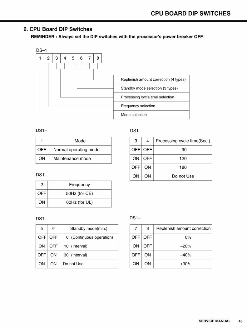
1 2 3 4 5 6 7 8
Replenish amount correction (4 types)
Standby mode selection (3 types)
Processing cycle time selection
Frequency selection
Mode selection
DS–1
1 Mode
OFF Normal operating mode
ON Maintenance mode
DS1–
3 4 Processing cycle time(Sec.)
OFF OFF 90
ON OFF 120
OFF ON 180
ON ON Do not Use
DS1–
7 8 Replenish amount correction
OFF OFF 0%
ON OFF –20%
OFF ON –40%
ON ON +30%
DS1–
5 6 Standby mode(min.)
OFF OFF 0 (Continuous operation)
ON OFF 10 (Interval)
OFF ON 30 (interval)
ON ON Do not Use
DS1–
2 Frequency
OFF 50Hz (for CE)
ON 60Hz (for UL)
DS1–
6. CPU Board DIP SwitchesREMINDER : Always set the DIP switches with the processor's power breaker OFF.

47 SERVICE MANUAL
CHECKING CIRCUIT BOARDS, SENSORS AND ELECTRICAL LOADS
7. Checking Circuit Boards, Sensors and Electrical LoadsREMINDER : After performing each check and related adjustment, switch the power breaker
OFF, then back ON again.
7-1. Circuit Boards
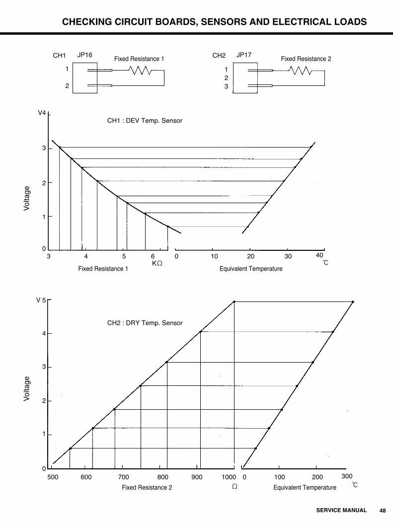
7-2. Sensors (Refer to CPU board in the above table)CH1 : DEV Temp. Sensor (Table 1) CH2 : DRY Temp. Sensor (Table 2)
Speed of temperature rise:
DEV about 1.07:/min
DRY about 80:/min
NOTE : These values are under the condition that surrounding temp. is 20:(68<) until the FIX temp. gets to 28:(82.4<).
Resistivity Voltage Temperature (KΩ) (V) Setting (:)
3.3 3.05 36.1
3.6 2.69 33.5
3.9 2.44 31.7
4.3 2.06 29.0
4.7 1.72 26.6
5.1 1.43 24.5
5.6 1.08 22.0
6.2 0.72 19.4
Resistivity 2 Voltage Temperature(Ω) (V) Setting (:)
510 0.10 6
560 0.57 34
620 1.13 68
680 1.71 103
750 2.40 144
820 3.10 186
910 4.00 240
1K 4.93 296
Board
CPU Board
Circuit
Power source
circuit
Reset circuit
Power sourcecircuit for temp.control.
VoltageConvertercircuit (CH1)
VoltageConvertercircuit (CH2)
Adjustment Point
The VR at the side of the DCpower source terminal block.
None(replace when out of adjustment)
None (replace when out of adjustment)
None (replace when out of adjustment)
VS3 on the CPU Board.
VS1 on the CPU Board.(DEV Temp. side)
VS2 on the CPU Board.(DRY Temp. side)
Correct Voltage
DC12.8±0.1V
DC5.0±0.2V
DC5.0±0.2V
less than DC5.0V
DC5.0±0.01V
Table 1 value±0.07V
Table 2 value±0.07V
Check Points
TP1-GND
TP2-GND
TP5-GND
TP5-GND(Check with power breaker OFF)
TP15-GND
TP12-GND
TP13-GND
48SERVICE MANUAL
CHECKING CIRCUIT BOARDS, SENSORS AND ELECTRICAL LOADS
CH1 CH2
1
2
1
32
JP16 JP17Fixed Resistance 1 Fixed Resistance 2
CH1 : DEV Temp. Sensor
Fixed Resistance 1 Equivalent Temperature
Fixed Resistance 2 Equivalent Temperature
500 600 700 800 900 0 100 200 3001000Ω :
3 4 5 6KΩ
10 20 30 40:
0
Vol
tage
V4
3
2
1
0
Vol
tage
V 5
4
3
2
1
0
CH2 : DRY Temp. Sensor

49 SERVICE MANUAL
CHECKING CIRCUIT BOARDS, SENSORS AND ELECTRICAL LOADS
7-3. Load Outputs and Control Panel Inputs
q Make sure that the power breaker is OFF.
w Set Dip switch (DS1-1) on the CPU board to the ON position.
e Select the desired processing cycle time by setting DIP switch (DS1-3,4) on the CPU board.
r Make sure that connector JP2 from the Control Panel is connected properly to JJ2 on the
CPU Board.
t Switch the power breaker ON, then switch over to the maintenance mode.
y Press and hold down th Replenish Button. Each of the loads will be indicated at 2 second
intervals in the order shown in the following table. Release the switch to select the desired
load.
u Turn the RUN Button ON and OFF, and you can decide the load selected in the y to ON or
OFF.
No.3 No.4 Processing cycle time(Sec.)
OFF OFF 90
ON OFF 120
OFF ON 180
ON ON Do not Use
DS1–
Order Load Check Point
1 READY Lamp READY Lamp ON
2 RUN Lamp RUN Lamp ON
3 DEV heater CPU Board LED1 ON
4 DRY heater CPU Board LED2 ON
5 Circulation pumps CPU Board LED6 ON
6 DEV supply pump CPU Board LED5 ON
7 FIX supply pump CPU Board LED4 ON
8 Electromagnetic valve CPU Board LED3 ON
9 Alarm (on CPU Board) Alarm will sound
10 Drive motor (at processing) Verify by sight
11 Drive motor (on standby) Verify by sight
Return to READY Lamp
50SERVICE MANUAL
CHECKING CIRCUIT BOARDS, SENSORS AND ELECTRICAL LOADS
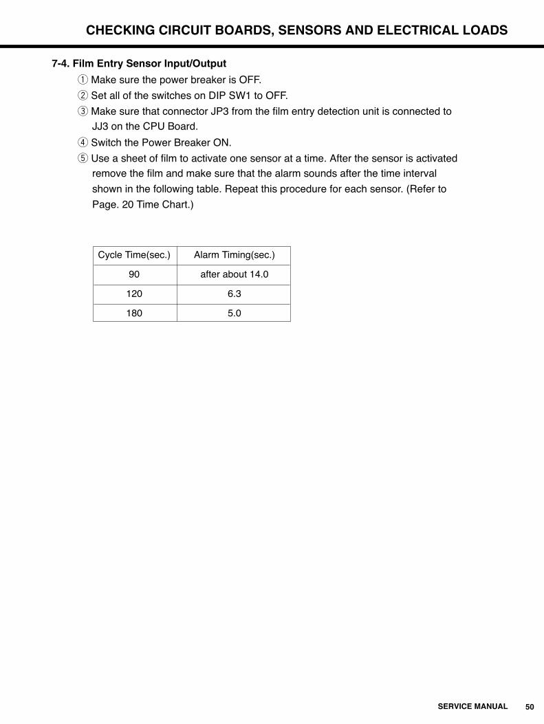
7-4. Film Entry Sensor Input/Output
q Make sure the power breaker is OFF.
w Set all of the switches on DIP SW1 to OFF.
e Make sure that connector JP3 from the film entry detection unit is connected to
JJ3 on the CPU Board.
r Switch the Power Breaker ON.
t Use a sheet of film to activate one sensor at a time. After the sensor is activated
remove the film and make sure that the alarm sounds after the time interval
shown in the following table. Repeat this procedure for each sensor. (Refer to
Page. 20 Time Chart.)
Cycle Time(sec.) Alarm Timing(sec.)
90 after about 14.0
120 6.3
180 5.0

51 SERVICE MANUAL
DEVELOPER TEMPERATURE CORRECTION
8. Developer Temperature CorrectionPerform the following adjustment procedure whenever there is any difference between the value of the DEV Temp. Setting Volume on the temperature control board and the actual developersolution temperature in the developing tank.q Make sure that the Power Breaker is OFF and set the DEV Temperature Setting Volume to 34:.w Switch the Power Breaker ON and press the RUN button.e Measure the voltage between TP15 and TP14 (GND) on the CPU Board. Turn the Standard
Voltage Output Control Volume (VR5/VS3) on the temperature control board so that thevoltage measures 5.0V±0.01V.
r Wait for five minutes after the READY lamp comes ON and then measure the temperature ofthe solution in the developer tank.
t Perform the following calculation, turn the DEV Temp Output Correction Volume (VR4/VS1) on thetemperature control to adjust the voltage between TP12 and TP14 (GND) by the calculated result.EXAMPLE :
When the temperature of the developer in the tank is 34.5:. The correction value is :(34.5–34.0) x 0.14 (fixed value) =0.07V
The voltage should therefore be increased by 0.07.
Temperature Control Section on CPU Board
DRY Temp Output Control Volume VR2/VS2
DRY Temp Sensor Connector JJ17
DRY Temp Setting Volume VR9
DEV Temp output Control Volume VR4/VS1
DEV Temp Sensor Connector JJ16
DEV Temp setting Volume VR7
Reference Voltage Output Control Volume VR5/VS3
ELECTRICAL COMPONENTS DIAGRAM
52SERVICE MANUAL CE
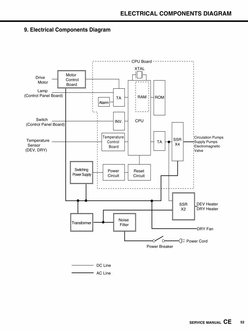
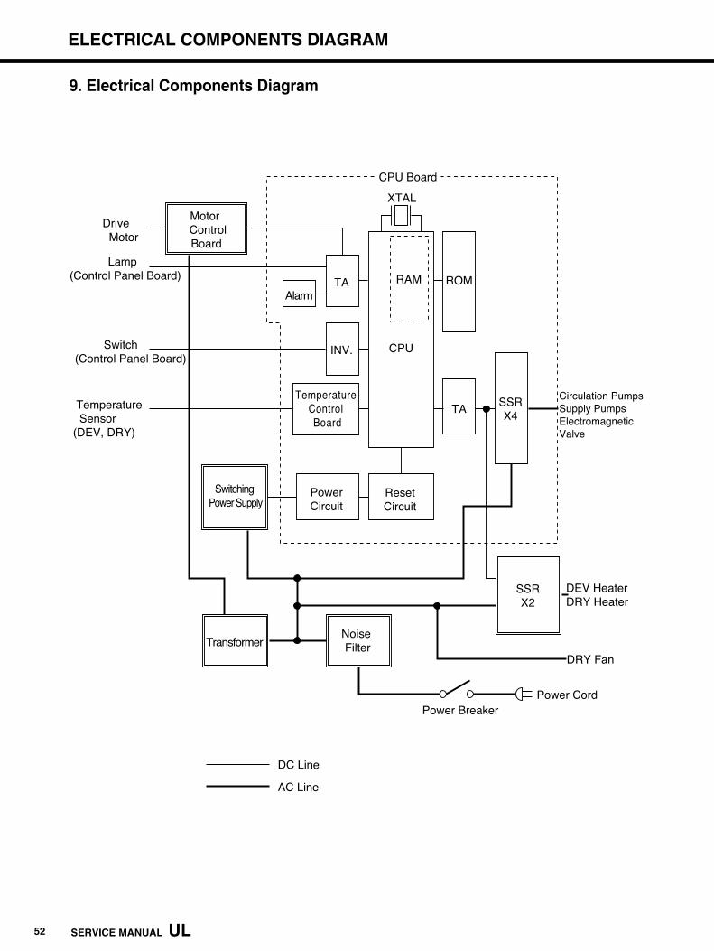
Motor Control
Board
Drive Motor
Lamp(Control Panel Board)
Switch(Control Panel Board)
Temperature Sensor(DEV, DRY)
CPU Board
XTAL
CPU
RAM ROM
TA
TA
INV.
Temperature Control Board
PowerCircuit
Switching Power Supply
ResetCircuit
SSRX4
Alarm
SSRX2
Noise FilterTransformer
Circulation PumpsSupply PumpsElectromagnetic Valve
DEV HeaterDRY Heater
DRY Fan
Power CordPower Breaker
DC Line
AC Line
9. Electrical Components Diagram
52 SERVICE MANUAL UL
ELECTRICAL COMPONENTS DIAGRAM
Motor Control
Board
Drive Motor
Lamp(Control Panel Board)
Switch(Control Panel Board)
Temperature Sensor(DEV, DRY)
CPU Board
XTAL
CPU
RAM ROM
TA
TA
INV.
Temperature Control Board
PowerCircuit
Switching Power Supply
ResetCircuit
SSRX4
Alarm
SSRX2
Noise FilterTransformer
Circulation PumpsSupply PumpsElectromagnetic Valve
DEV HeaterDRY Heater
DRY Fan
Power CordPower Breaker
DC Line
AC Line
9. Electrical Components Diagram

SERVICE MANUAL CE 53
10. Wiring Diagram of Main Unit (CE)
SERVICE MANUAL UL 53
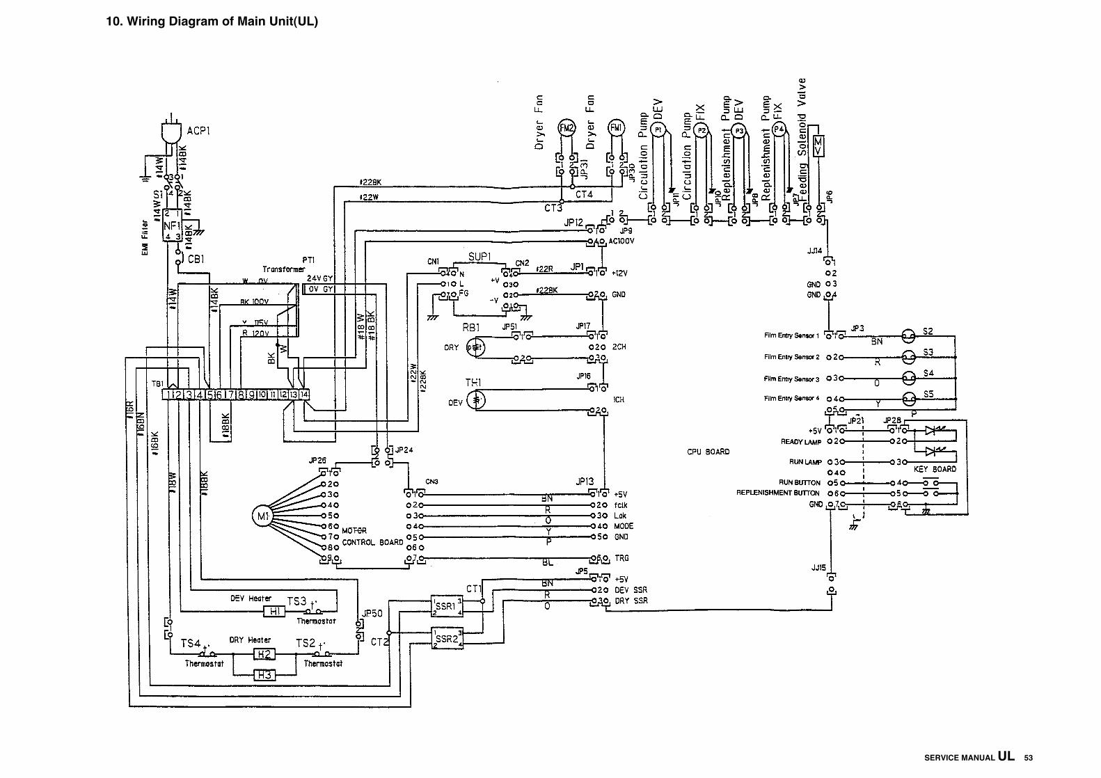
10. Wiring Diagram of Main Unit(UL)

WIRING DIAGRAM OF MAIN UNIT
54SERVICE MANUAL
Main Body Electric Circuit Parts List
Symbol Name Manufacturer(UL/CE) Model(UL/CE) Remarks
S1 Switch Matsushita AJB201R
S2~5 Reed switch Japan AutomationCo. RS-9S
Reed switch magnet Japan AutomationCo. RS-9M
NF1 Noise filter Nemic Ramda MAF-1220-33
TB1 Terminal block Osada OTB-525-14P-06-C
CB1(CB3) Circuit protector AMF W28XQ1A15 CB3: Only for CE
SSR1 SSR Matsushita/JEL SF12DPS-H1-4/S5C-215L-V
SSR2 SSR Matsushita/JEL SF20DPS-H1-4/S5C-225L-V
PT1 Transformer KWAN-CHIU WC-37Y/WC-38
SUP1 Switching power supply Nemic Ramda VS15B-12/RWS15A-12
M1 Drive motor Kokusan Electric
FM1, 2 DRY fan Japan Servo Co. CB55B4-Y
MV Electromagnetic valve CKD J248-676
P1, 2 Magnet pump Iwaki MD-6-NL09
P3, 4 Bellows pump Iwaki KBR-3XAU1M-S12
H1 DEV heater Shinnetsu Kogyo
H2, 3 DRY heater unit Asahi Glass
TS2, 4 Overheat switch Elmwood 8209-72-L140C
TS3 Overheat switch Elmwood 2455RBV-117-207
JP1, 6~8, 10, 11, 24, 30, 31, 51 Connector Molex 5557-02R
JP2, 25 Connector Molex 5102-07
JP3 Connector Molex 5102-05
JP4, 20 Connector Molex 5102-08
JP5, 22 Connector Molex 5102-03
JP12, 50 Connector Molex 5557-04R
JP13 Connector Molex 5102-06
JP14 Connector Molex 5102-04
JP21 Connector Molex 5102-02
JP26 Connector AMP 171822-9
JP28 Connector Molex 5102-06
JJ30, 31 Connector Molex 5559-02P
ACP1 Power cord with plug Kawasaki Densen No.28495 (UL) L=2.81m
Philips 57226604618 (CE) L=3.55m
CPU board Special parts
Control Panel board Special parts
Motor control board Special parts

SERVICE MANUAL 55
11. Circuit Board Diagram
11-1. CPU Board

56SERVICE MANUAL
CPU Board Parts Lists (1)
Symbol Name Manufacturer M o d e l Remarks
IC1 CPU NEC μPD78C10AGF-3BE
IC2 ROM TI TMS27C512-15 SRX-101A
IC3 TTL Toshiba TC74HC573AF
IC4, IC5 TTL Toshiba TC74HC7240AF
IC6 Power voltage IC Fujitsu MB3771PF-G-BND
IC7 TTL Toshiba TC74HC00AF
IC8 3 Point Regulator Toshiba TA7805S
IC9 3 Point Regulator Toshiba TA78L06F
IC10 Ope. amp. Rohm BA10324AF TA75324F Toshiba
TA1, TA2 Sink screwdriver Toshiba TD62381FN
LED1~6 LED Toshiba TLSU1002 Red
PC1 Photocoupler Toshiba TLP181GR
D1~11 Shotkey Diode Nippon Inter EC10QS04 U1GWJ44 Toshiba
D12 Diode Toshiba UIBC44
SSR3-6 Solid state relay Matsushita AQ80139-G01 TUV, UL, CSA
L1 Choking coil Tokin Corporation SN-8S-500
RA1~7 Resistor array Beckman M9-1-4721 1/8W 4.7KΩ
R1 Tip Resistor MICRON MNS05N180JC
R2, R3, R9, R39 Tip Resistor Rohm MCR18EZH102F 5W 18KΩ
R4 Tip Resistor Rohm MCR18EZH201J 1/8W 1KΩ F
R5,R6 Tip Resistor Rohm MCR18EZH104J 1/8W 200Ω
R7,R8 Tip Resistor Rohm MCR18EZH512J 1/8W 100KΩ
R10 Tip Resistor KOA RN73G2ATD392F 1/8W 5.1KΩ
R11 Tip Resistor KOA RN73G2ATD113F 1/10W 3.9KΩ F
R12, R16, R47 Tip Resistor Rohm MCR18EZH301F 1/10W 300KΩ F
R13, R22, R35 Tip Resistor Rohm MCR18EZH103F 1/8W 10Ω F
R14 Tip Resistor Rohm MCR18EZH683F 1/8W 68KΩ F
R15 Tip Resistor Rohm MCR18EZH512F 1/8W 5.1KΩ F
R17, R18, R30, R31 Tip Resistor Rohm MCR18EZH203F 1/8W 20KΩ F
R19 Tip Resistor Rohm MCR18EZH204F 1/8W 200KΩ F
R20 Tip Resistor Rohm MCR18EZH242F 1/8W 2.4KΩ F
R21 Tip Resistor Rohm MCR18EZH822F 1/8W 8.2KΩ F
R23, R36 Tip Resistor Rohm MCR18EZH512F 1/8W 5.1KΩ F
R25 Tip Resistor Rohm MCR18EZH163F 1/8W 16KΩ F
R26 Tip Resistor Rohm MCR18EZH561F 1/8W 560KΩ F
R27, R28 Tip Resistor Rohm MCR18EZH332F 1/8W 3.3KΩ F
R29 Tip Resistor Rohm MCR18EZH471F 1/8W 470KΩ F
R33 Tip Resistor Rohm MCR18EZH123F 1/8W 12KΩ F
R34 Tip Resistor Rohm MCR18EZH622J 1/8W 6.2KΩ
R41, R46 Tip Resistor Rohm MCR18EZH122F 1/8W 1.2KΩ F
R40 Tip Resistor Rohm MCR18EZH122J 1/8W 1.2KΩ
R42 Tip Resistor Rohm MCR18EZH162J 1/8W 1.6KΩ
R45 Tip Resistor Rohm MCR18EZH152J 1/8W 1.5KΩ
R43 Tip Resistor Rohm MCR18EZH392F 1/8W 3.9KΩ F
R44 Tip Resistor Rohm MCR18EZH221F 1/8W 220KΩ F
CIRCUIT BOARD DIAGRAM

57 SERVICE MANUAL
CIRCUIT BOARD DIAGRAM
CPU Board Parts Lists (2)
Symbol Name Manufacturer Model Remarks
R32 Tip Resistor Rohm MCR18EZH104F 1/8W 100Ω F
R38 Tip Resistor Rohm MCR18EZH121F 1/8W 120Ω F
R24, R37 Tip Resistor Rohm MCR18EZH101F 1/8W 100Ω F
C17, C18, C19, C20, C22, C23, C24 Ceramic tip capacitor Murata GRM42-6R104K50 0.1µF/50V
C2, C11 Ceramic tip capacitor Murata GRM40CH102J50 1000pF/50V
C5, C6 Ceramic tip capacitor Murata GRM40CH100D50 10pF/50V
C3 Tantale capacitor NEC MSVA1E105M 1µF/25V
C15 Electrolytic capacitor Nippon chemicon KME25VB-1000M 1000µF/25V
C13 Electrolytic capacitor Nippon chemicon KME25VB-470M 470µF/25V
C1, C4, C7~10, C12, C14, C16, C27 Ceramic tip capacitor Murata GRM40F104Z50 0.1µF/50V Pascon
C21 Both typeelectrolytic Nippon chemicon MVK35VC10MBPF60 10µF/35V
C25 Electrolytic capacitor Nippon chemicon MVK25VC47MH63 47µF/25V
C26 Electrolytic capacitor Nippon chemicon MVK35VC10ME55 10µF/35V
LC1 Emifil Murata DSS306-55B271M100
VR1~3, VR6, VR8 Thermet trimmer Kopal CT-6P102J 1KΩ
VR7, VR9 Thermet trimmer Kopal RJ-6P102J 1KΩ Round shape
VR4 Thermet trimmer Kopal CT-6P202J 2KΩ
VR5 Thermet trimmer Kopal CT-6P101J 100KΩ
X1 Crystal Kaneishi HC-49/U–S7.3728MHz
BZ1 Buzzer Star Mfg. KMB-06
DS1 DIP Switch OMRON A6B8101
(IC2) ICSocket Matsushita AXS102813 28pin(For ROM)
TO1~5, TO7~17 Check Terminal Mac Eight HK-2-G For check TO6luck
F1 Fuse Ritel 2183. 15
FH1 Fuse holder Nagasawa Electric FP-217
(IC9) Heat sink Ryosan 0SH-2425-SP25 For TA7805S
JJ1, JJ6~11 Connector Molex 5566-02A JJ9 isn't contained.
JJ2 Connector Molex 5045-07A
JJ3 Connector Molex 5045-05A
JJ5, JJ17 Connector Molex 5045-03A
JJ12 Connector Molex 5566-04A
JJ13 Connector Molex 5045-06A
JJ14, JJ18 Connector Molex 5045-04A
JJ15, JJ16 Connector Molex 5045-02A JJ15 isn't contained.
JP1 Rapping terminal Mac Eight WL-1 connected to 34pin.
JP2 Rapping terminal Mac Eight WL-1 connected to 34 pin
JPP1, JPP2 Jaump socket Mac Eight JS-1
Silicon rubbar Shinetsu TC-30BG For T0-220 TA7805S
M3 Screw For TA7805S
Print Board Sougou circuit
58SERVICE MANUAL
CIRCUIT BOARD DIAGRAM
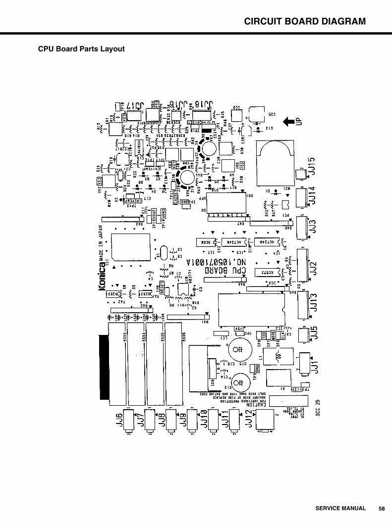
CPU Board Parts Layout

59 SERVICE MANUAL
CIRCUIT BOARD DIAGRAM
11-2. Control Panel Board Circuit Diagram
KEY Board Parts List
KEY Board Parts Diagram
Symbol Name Manufacturer M o d e l Remarks
S1, 2 Switch Fuji Electric AB12-EA137
S1, S2 Push Button Fuji Electric ABX112-H
LED1, 2 LED Toshiba TLR218P
LED3 LED Stanley Electric MPR3338S
R1 Resistor Matsushita ERD-25TJ202 2kΩ/1/4W
JJ28 Connector Molex 5045-06A
Print Board Special part
LED2
LED1 LED3
6
S2 S1
R11
JJ28
1+5V
JJ28
LED 2Ready Lamp
LED 3RUN Lamp
SW 4RUN Button
SW 5ReplenishButton
6GND
LED 1
LED 2
LED 3
R1S1
S2
34
12
34
12
SERVICE MANUAL 60
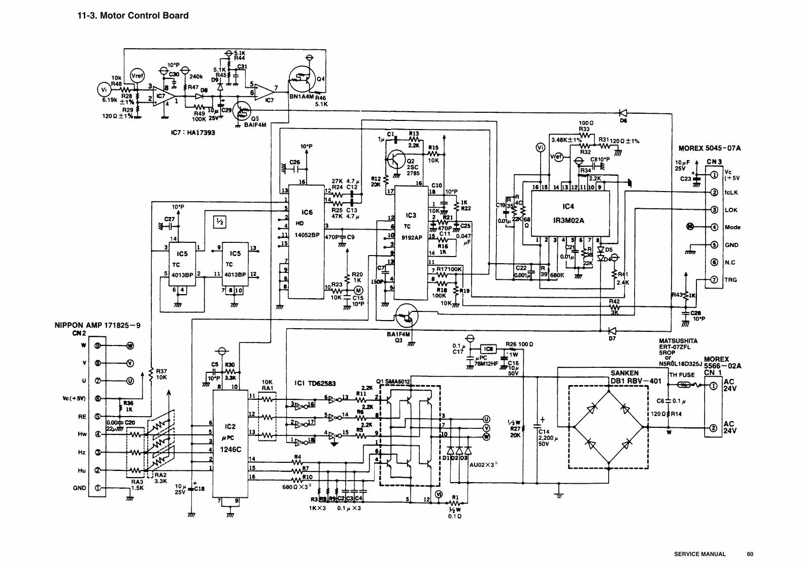
11-3. Motor Control Board

61SERVICE MANUAL
CIRCUIT BOARD DIAGRAM
Motor Control Board Parts List (1)
Symbol Name Manufacturer M o d e l Remarks
IC1 IC Toshiba TD62583AP
IC2 IC NEC μPC1246C
IC3 IC Toshiba TC9192AP or Toshiba TC9192P
IC4 IC Sharp IR3M02A
NEC μPC494C
IC5 IC Toshiba TC4013BP or Motroller MC14013BCP
IC6 IC Hitachi HD14052BP
NEC μPD4052BP
Toshiba TC4052BP
IC7 IC Hitachi HA17393
NEC μPC393C
IC8 IC NEC μPC78M12AHF or NEC μPC78M12HF
Q1 Transistor Array Sanken SMA6012 or Sanken SLA6012
Q2 Transistor NEC 2SC2785
Q3, 5 Transistor NEC BA1F4M
Rohm DTC124
Q4 Transistor NEC BN1A4M
D1~3 Diode Sanken AU02V1
Sanken AU02V0
Hitachi DFA1A2
D4~9 Diode Hitachi 1S2076A
NEC 1S953
DB1 Diode array Sanken RBV-401
RA1 Resistor array Matsushita EXB-F6V103J(Y)
KOA RKCB3S103J
Rohm RMHA3-103J
RA2 Resistor array Matsushita EXB-F4E332J(Y)
KOA RKCB3332J
Rohm RMLS3-332J
RA3 Resistor array Matsushita EXB-F6V152J(Y)
KOA RKCB3S152J
Rohm RMHA3-152J
C1 Condenser Nichicon UEB1H010MAA 1μF/±50V
Nichicon UVP1H010MAA
Nippon Chemi-con SME50VB1BP
C2~4, 17 Condenser NEC TPD33Y5V1E104ZL-W 0.1μF/25V
NEC D33Y5V1EN104Z-51
C5, 8, 10, 15, 26~28, 30, 31 Condenser Matsushita ECK-PH1032ZF 10.000pF/50V
C6 Condenser Nissei Electric MMTV104J50 0.1μF/50V
Nichicon QYA1H104K
C7 Condenser Matsushita ECC-R1H151JC4 150pF/50V
C9, 11 Condenser Matsushita ECK-R1H471KB 470pF/50V
C12, 13 Condenser Nichicon UEB1E4R7MAA 4.7μF/±25V
Nichicon UVP1E4R7MAA

62 SERVICE MANUAL
CIRCUIT BOARD DIAGRAM
Motor Control Board Parts List (2)
Symbol Name Manufacturer M o d e l Remarks
C14 Condenser Matsushita ECES1HU222EG 2,200μF/50V
Nichicon LLK1H222MHSZ
C16 Condenser Nichicon UVZ1H100MAH 10μF/50V
Nichicon UPC-1H100MA1HS
C18, 23, 29 Condenser Nichicon ULB1E100MAA 10μF/25V
Nichicon UVX1E100MAA
Nippon Chemi-con SME25VB10
C19, 21 Condenser Nissei Electric AMZV103K50 0.01μF/50V
Nichicon QYA1H103K
Nichicon QYX1H103K
C20 Condenser Nissei Electric AMZV222K50 0.0022μF/50V
Nichicon QYA1H222K
Nichicon QYX1H222K
C22 Condenser Nissei Electric AMZV102K50 0.001μF/50V
Nichicon QYA1H102K
Nichicon QYX1H102K
C25 Condenser Nissei Electric AMZV473K50 0.047μF/50V
Nichicon QYA1H473K
TH Thermistor Oizumi N5R0L18D325J or Matsushita ERT-D7ZFL5R0P
R1 Resistor Matsushita ERX-12-SJR20 0.2Ω/1/2W
Rohm CRH50JXR20
R3, 8, 9, 16, 20, 22, 36, 43 Resistor Matsushita ERD-S2-TJ102 1kΩ/1/4W
Matsushita ERD25VJ102
R4, 7, 10 Resistor Matsushita ERD-S2-TJ681 680Ω/1/4W
Matsushita ERD25VJ681
R5, 6, 11, 13, 34 Resistor Matsushita ERD-S2-TJ222 2.2kΩ/1/4W
Matsushita ERD25VJ222
R12 Resistor Matsushita ERD-S2-TJ203 20kΩ/1/4W
Matsushita ERD25VJ203
R14 Resistor Matsushita ERG-1-SJ121V 120Ω/1W
R15, 19, 21, 23, 37 Resistor Matsushita ERD-S2-TJ103 10kΩ/1/4W
Matsushita ERD25VJ103
R17, 18, 49 Resistor Matsushita ERD-S2-TJ104 100Ω/1/4W
Matsushita ERD25VJ104
R24 Resistor Matsushita ERD-S2-TJ273 27kΩ/1/4W
R25 Resistor Matsushita ERD-S2-TJ473 47Ω/1/4W
Matsushita ERD25VJ473
R26 Resistor Matsushita ERG-1-SJ101V 100Ω/1W
R27 Resistor Matsushita ERD50TJ203 20kΩ/1/2W
Rohm R50XJ20KΩ
R28 Resistor Matsushita ERO-S2-CKF6191 6.19kΩ±1%/1/4W
R30 Resistor Matsushita ERD-S2-TJ332 3.3kΩ/1/4W
Matsushita ERD25VJ332 120Ω±1%/1/4W
R31, 29 Resistor Matsushita ERO-S2-CKF1200 3.48kΩ±1%/1/4W
R32 Resistor Matsushita ERO-S2-CKF3481 100Ω/1/4W

63SERVICE MANUAL
CIRCUIT BOARD DIAGRAM
Motor Control Board Parts List (3)
Symbol Name Manufacturer M o d e l Remarks
R33 Resistor Matsushita ERD-S2-TJ101 100Ω/1/4W
Matsushita ERD25VJ101
R35, 38 Resistor Matsushita ERD-S2-TJ223 22kΩ/1/4W
Matsushita ERD25VJ223
R39 Resistor Matsushita ERD-S2-TJ684 680kΩ/1/4W
Matsushita ERD25VJ684
R40 Resistor Matsushita ERD-S2-TJ680 68Ω/1/4W
Matsushita ERD25VJ680
R41 Resistor Matsushita ERD-S2-TJ242 2.4kΩ/1/4W
Matsushita ERD25VJ242
R42 Resistor Matsushita ERD-S2-TJ302 3kΩ/1/4W
Matsushita ERD25VJ302
R44~46 Resistor Matsushita ERD-S2-TJ512 5.1kΩ/1/4W
Matsushita ERD25VJ512
R47 Resistor Matsushita ERD-S2-TJ244 240kΩ/1/4W
Matsushita ERD25VJ244
F1 Fuse RITEL 21802.5 250V, 2.5A
F1 Fuse Holder Emuden Musen H-0452
CN1 Connector Molex 5566-02A
CN2 Connector AMP 171825-9
CN3 Connector Molex 5045-07A
Print board
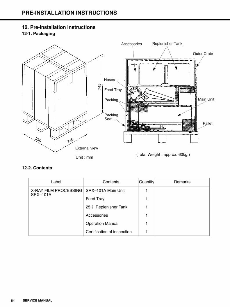
64 SERVICE MANUAL
PRE-INSTALLATION INSTRUCTIONS
12. Pre-Installation Instructions12-1. Packaging
Unit : mm
12-2. Contents
Label Contents Quantity Remarks
X-RAY FILM PROCESSING SRX–101A Main Unit 1SRX–101A
Feed Tray 1
25R Replenisher Tank 1
Accessories 1
Operation Manual 1
Certification of inspection 1
External view
745
745930
Replenisher Tank
(Total Weight : approx. 60kg.)
Accessories
Outer Crate
Main Unit
Pallet
Hoses
Feed Tray
Packing
PackingSeat
65SERVICE MANUAL
PRE-INSTALLATION INSTRUCTIONS
12-3. Package Contents Verification
Before installing the SRX-101A, make sure to check the main unit and accessory equipment
for any missing parts or damage during transportation.
(1) Check to see if the model name and numbers printed on the outside of the package
correspond to what the customer ordered.
(2) Check if there is any extraordinary damage to the outside of the package.
(3) Open the package while following the precautions outline in the next section.
(4) Check if there is any missing parts by matching the contents of the package with the
packing list provided.
(5) Check all the parts for any external damage.
NOTE :
If there are any missing parts or damage, notify your local KONICA representative immediately.
12-4. Precautions ti Take When Opening the Package
(1) At least two persons are needed to hand-carry the SRX-101A.
(2) Be careful when cutting the bands away from the package. They have been bound tightly
and could cause injury when released.
(3) The racks have been wrapped in plastic sheets.
There is cushioning material between the racks and processing tanks.
Remove carefully and dispose of all these materials before beginning installation.
12-5. Opening the Package
(1) Use scissors to cut the bands.
(2) Cut the top of the outer crate open with a utility knife.
(3) Lift the box of accessories up and out over the top of the crate. This package contains the
replenisher tank and other accessories.
(4) Lift the outer crate up and over the main unit.
(5) Remove the Feed Tray.
(6) Unload the Main Unit from the pallet.
At least two persons are necessary to lift and transport the processor.

66 SERVICE MANUAL
PRE-INSTALLATION INSTRUCTIONS
25R Replenisher Tank
ID. NO. Parts Name Qty Remarks
1 Hose band 2 Tyton. SNP–12–HSO
2 Replenisher pipe (DEV) 1
3 Replenisher pipe (FIX) 1
4 Replenisher filter 2
5 Filter cap 2
6 Name plate(DEV) 2
7 Stirring rod(DEV) 1 (yellow)
8 Floating lid 2
9 Clamp 2 Kitagawa Industrial Co. LTD.CKS-16-H
10 Name plate(FIX) 2
11 Replenisher tank 2
12 Stirring rod (FIX) 1 (red)

67SERVICE MANUAL
PRE-INSTALLATION INSTRUCTIONS
25R Replenisher Tank

68 SERVICE MANUAL
PRE-INSTALLATION INSTRUCTIONS
Set of Accessories
ID.No. Parts Name Qty
1 Gear 1
2 Idler gear 1
3 Gear 1
4 Idler gear 1
5 Stopper 1
6 Shaft support 1
7 Coil spring 2
8 Coil spring 2
9 Rubber pad 4
10 Bushing 1
11 Packing 1
12 Funnel 1
13 Plastic beaker(Measuring cup) 1
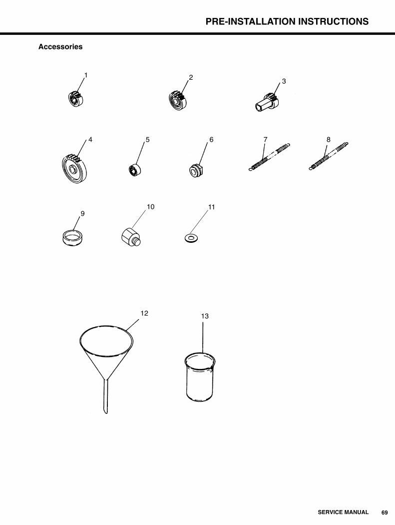
69SERVICE MANUAL
PRE-INSTALLATION INSTRUCTIONS
Accessories
12 13
1
4
910 11
5 6 7 8
2 3

70 SERVICE MANUAL
INSTALLATION INSTRUCTIONS AND PRECAUTIONS
13. Installation Instructions and Precautions13-1. Space Requirements
The accompanying diagram shows the minimum space required to operate, maintain and repair the
SRX-101A. Any space smaller than these dimensions will result in longer shutdown times during
maintenance and repair.
13-2. Setting the Main Unit in place (Refer to the Diagram Below)q Place the Main Unit on the Stand (Option), a desk or a work bench so that the supply and
drainage valves are easily accessible.
w The SRX-101A, when filled with processing solutions, weighs approximately 47 kg. Make
sure that the support to be used is more than capable of bearing this weight and also
resistant to the corrosive effects of the developer (PH 11) and fixer (PH 4) chemicals.
e Do not install the processor in high vibration areas or where it cannot be properly leveled.
r Place the SRX-101A at a height from the floor that fulfills both of the following conditions.
a. The liquid surface inside the replenisher tank is below the full marks of the main unit
processing tanks.
b. The top of the main unit support is less than 130cm from the floor or other surface where the
replenish tank is standing.
At least 60cm
At least 60cm
At least 60cm
SRX–101AAt least 25cm
Drainage Valves
Adjustable Stands
Max.130cm
Binding Tape
Developer Supply Hose (Yellow)
Fixer Supply Hose (Red)
Developer Drainage Hose (Yellow)
Fixer Drainage Hose (Red)
Wash Water Drainage Hose(Thick, Transparent)
Overflow Drainage Hose(Thin, Transparent)
Water Supply Hose
with thread

71SERVICE MANUAL
INSTALLATION INSTRUCTIONS AND PRECAUTIONS
13-3. Connecting the Supply Hosesq Connect the supply hoses to the 25 liter replenisher tank.
Yellow • • • • • • • • • • • •DEV Supply Hose.
Red • • • • • • • • • • • • • •FIX Supply Hose.
w Use SNP-12-HSO to clamp the hoses to the tank.
NOTE :Do not extend any of the hoses more than 5 meters in length. If these 12 mm diameter hosesare extended longer than 5 meters, they tend to bend and collapse.
13-4. Connecting the Drainage Hosesq Connect the drainage hoses to the 25 liter replenisher tank.
Yellow • • • • • • • • • • • •DEV Drainage Hose
Red • • • • • • • • • • • • • •FIX Drainage Hose
Transparent(Thick) • • • •Water Drainage Hose.
Transparent(Thin) • • • • •Overflow Drainage Hose
w String the chemical and water drainage hoses so that no liquid will accumulate in the hoses
between the main unit and the drainage tank or the water drain.
13-5. Power Source and Wiringq Changing the terminal Board to Meet Voltage Requirements
Follow these procedure in changing the connection to terminal board
TB1 located on the top of the electrical components unit.
£ £ £ £ £ £ £ £ £ £ £ £ £ £
£ £ £ £ £ £ £ £ £ £ £ £ £ £
1 2 3 4 5 6 7 8 9 10 11 12 13 14
Black Wire
w q q For AC 120V outlets, connect terminals #5 and #8.
w For AC 115V outlets, connect terminals #5 and #7.
gg
£ £ £ £ £ £ £ £ £ £ £ £ £ £
£ £ £ £ £ £ £ £ £ £ £ £ £ £
1 2 3 4 5 6 7 8 9 10 11 12 13 14
Black Wire
w q q For AC 240V outlets, connect terminals #5 and #9.
w For AC 230V outlets, connect terminals #5 and #8.
e For AC 220V outlets, connect terminals #5 and #7.
gg
e
g
UL Version
CE Version

72 SERVICE MANUAL
INSTALLATION INSTRUCTIONS AND PRECAUTIONS
w Select an electrical outlet that is equal to or above the required current and voltage to operate
the processor and use this outlet for the SRX-101A only.
Insufficient current to the processor may cause overheating and/or smoking.
e The power source voltage to the processor should be within a range of ±10% of the specified
requirement. The frequency (Hz) value should be within a range of ±2.5% of the specified
requirements.
r Lay the power cord so that it is clear of foot traffic, sharp objects and other equipment.
Damaged plugs and cords may cause the processor to overheat and/or smoke.
t To prevent overheating or smoking, do not connect the processor to table top outlets, junction
cords or junction outlets.
y The power cord provided as standard equipment is 2.6 meters in length. If an extension is
needed, use only legally specified (product liability standard) extension cords. Sub-standard
extension cords may cause the processor to overheat or smoke.
u To prevent electrocution accidents, properly ground the SRX-101A. To avoid the possibility of
explosions or electrocution, do not attempt to ground the processor to any of the following
objects.
Gas pipesLightening rodsTelephone ground wiresAny water line or spigot not permitted by your local water department.

73SERVICE MANUAL
INSTALLATION INSTRUCTIONS AND PRECAUTIONS
13-6. Room Conditions Around the SRX-101Aq The acceptable room conditions for operating the SRX-101A are :
Temperatures between 15: and 30:(59<and 86<)
Humidity levels between 30%RH and 75%RH
w In order to maintain the above room conditions, the facility where the SRX-101A is located
should be equipped with a ceiling mounted ventilation fan and a ventilation opening in the
wall below the height of the processor.
The ventilation wall opening should be as close to the processor as possible and as far
away from the ventilation fan as possible. Use light shielding materials for both the fan and
wall openings.
e Keep all fluorescent materials and combustible materials (thinner, benzene, gasoline.etc)
away from the processor. To prevent fires, store such dangerous materials in another
room.
r Divert heat from burners and space heaters away from the processor. Divert forced air
from air conditioning equipment away. Being exposed to direct blast of hot or cold air, poor
film processing quality may result.
Ex. Darkroom Ventilation
Ventilation Fan
Darkroom
Ventilation Opening(below the height of the processor)
SRX–101A

74 SERVICE MANUAL
INSTALLATION INSTRUCTIONS AND PRECAUTIONS
13-7. Water Linesq Connect a reducer bushing with a packing to the facility's water utility outlet.
w Connect the processor's water supply hose to the reducer bushing.
e Acceptable Wash Water Temperature 5:~30:(41<~86<)
Required Water Flow............................................................0.7~1.7R(0.19~0.47gal.)/min
Required Water Pressure .....................................................29.4~784kpa(0.3~8kgf)/cm2
r If water pressure is below 29.4kpa(0.3kgf)/cm2, over 0.7R(0.19gal.)/min Wash water
cannot be maintained.
In this case, a malfunction may occur. Increase the water pressure.
t If water pressure is exceeding 784kpa(8kgf)/cm2, use flow restrictor to reduce the water
pressure.
Excessive water pressure applied to the water line may cause the damage of the hoses.
13-8. Setting the Feed Tray in Placeq Use the pan-head screws provided to attach the feed tray to the main unit.
w Control panel can be attached to either side of the main unit.
Select the side which is more convenient to operate, considering the operating
environment.
13-9. Cleaning the Racksq Remove the DEV and FIX racks from the main unit.
w Scrub each rack(including the rollers) with a wet sponge to remove any dirt or grim and
then rinse with plain water. Lean the racks so that the remaining water can evacuate from
the racks.
Packing
SRX-101A Water Supply HoseFacility Water
Utility Outlet
PF3/4 PF1/2
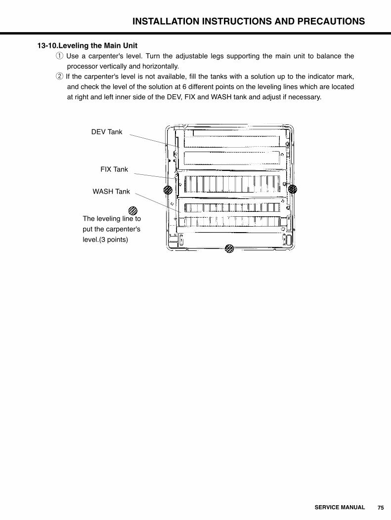
75SERVICE MANUAL
INSTALLATION INSTRUCTIONS AND PRECAUTIONS
13-10.Leveling the Main Unitq Use a carpenter's level. Turn the adjustable legs supporting the main unit to balance the
processor vertically and horizontally.
w If the carpenter's level is not available, fill the tanks with a solution up to the indicator mark,
and check the level of the solution at 6 different points on the leveling lines which are located
at right and left inner side of the DEV, FIX and WASH tank and adjust if necessary.
DEV Tank
FIX Tank
WASH Tank
The leveling line to
put the carpenter's
level.(3 points)

76 SERVICE MANUAL
INSTALLATION INSTRUCTIONS AND PRECAUTIONS
13-11.Setting the Racks
Make sure that there is no excess water remaining in the racks before setting them into the
main unit. The racks have been designed so that the DEV rack is set first, then the FIX-
WASH rack can be inserted. They cannot be set in the reverse order.
Set each rack into the main unit so that the arrows and names on the rack exactly overlap
the arrows and tank names on the main unit. (Refer to the diagram below)
If the arrows and names do not exactly match, the rack ribs will not slide into their grooves
and the racks will wobble in the tanks.
FIX-WASH Rack DEV Rack
WASH Tank FIX Tank DEV Tank
WASH FIX DEV
DEVFIXWASH

77SERVICE MANUAL
INSTALLATION INSTRUCTIONS AND PRECAUTIONS
13-12. Mixing the Processing Chemicals
When Using the 25 Liter Replenisher Tank, follow the direction that come with each pack of
developer and fixer.
1. The chemistry and starter fluid are dangerous to eyes, can causeskin irritation and damage clothing. Handle them with care. If youaccidentally splash chemistry on your skin or clothing,immediately wash the stained areas with water. If you splash anyof these chemistry in your eyes, immediately wash with water andget professional medical treatment.
2. To avoid accidents, strictly follow the directions for handling andmixing of chemistry.
CAUTION
DEV Rack
GrooveRack Rib
FIX/WASH Rack
GrooveRack Rib
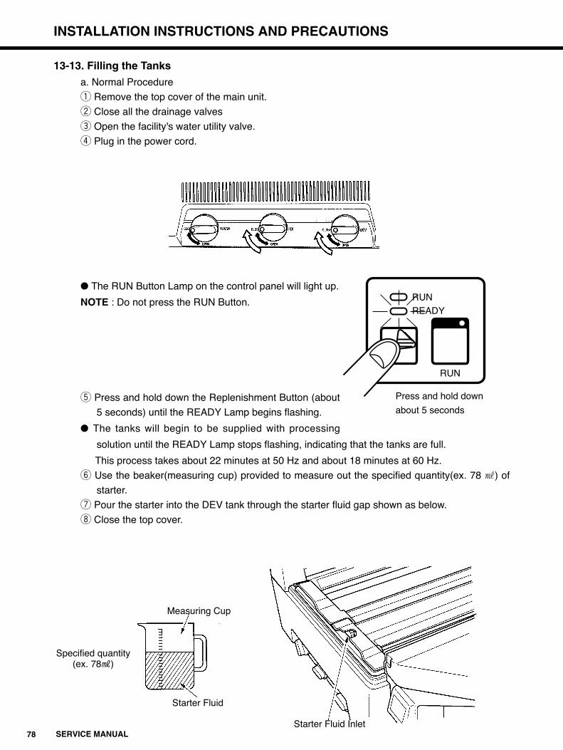
78 SERVICE MANUAL
INSTALLATION INSTRUCTIONS AND PRECAUTIONS
13-13. Filling the Tanks
a. Normal Procedure
q Remove the top cover of the main unit.
w Close all the drainage valves
e Open the facility's water utility valve.
r Plug in the power cord.
� The RUN Button Lamp on the control panel will light up.
NOTE : Do not press the RUN Button.
t Press and hold down the Replenishment Button (about
5 seconds) until the READY Lamp begins flashing.
� The tanks will begin to be supplied with processing
solution until the READY Lamp stops flashing, indicating that the tanks are full.
This process takes about 22 minutes at 50 Hz and about 18 minutes at 60 Hz.
y Use the beaker(measuring cup) provided to measure out the specified quantity(ex. 78 p) of
starter.
u Pour the starter into the DEV tank through the starter fluid gap shown as below.
i Close the top cover.
Starter Fluid
Measuring Cup
Specified quantity(ex. 78P)
Starter Fluid Inlet
RUNREADY
RUN
Press and hold down
about 5 seconds
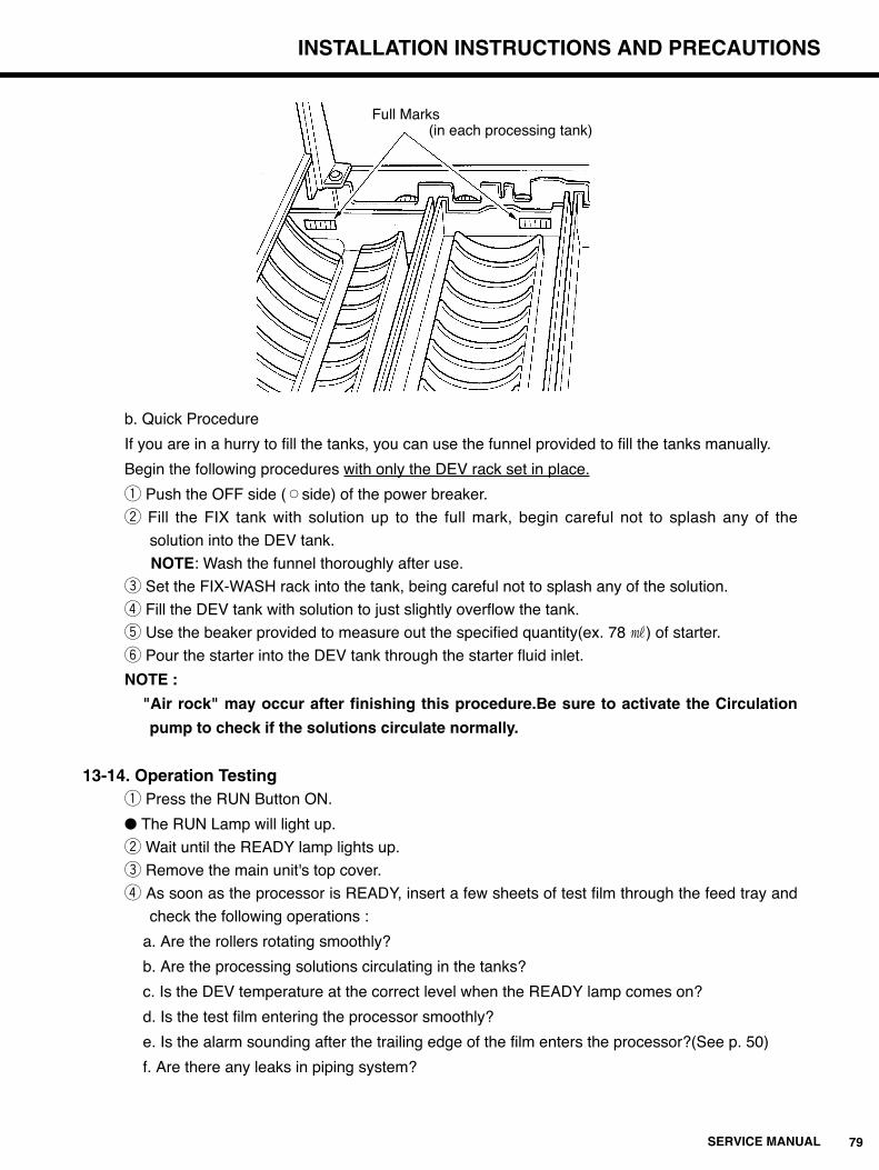
79SERVICE MANUAL
INSTALLATION INSTRUCTIONS AND PRECAUTIONS
b. Quick Procedure
If you are in a hurry to fill the tanks, you can use the funnel provided to fill the tanks manually.
Begin the following procedures with only the DEV rack set in place.
q Push the OFF side (™side) of the power breaker.
w Fill the FIX tank with solution up to the full mark, begin careful not to splash any of the
solution into the DEV tank.
NOTE: Wash the funnel thoroughly after use.
e Set the FIX-WASH rack into the tank, being careful not to splash any of the solution.
r Fill the DEV tank with solution to just slightly overflow the tank.
t Use the beaker provided to measure out the specified quantity(ex. 78 p) of starter.
y Pour the starter into the DEV tank through the starter fluid inlet.
NOTE :
"Air rock" may occur after finishing this procedure.Be sure to activate the Circulation
pump to check if the solutions circulate normally.
13-14. Operation Testingq Press the RUN Button ON.
� The RUN Lamp will light up.
w Wait until the READY lamp lights up.
e Remove the main unit's top cover.
r As soon as the processor is READY, insert a few sheets of test film through the feed tray and
check the following operations :
a. Are the rollers rotating smoothly?
b. Are the processing solutions circulating in the tanks?
c. Is the DEV temperature at the correct level when the READY lamp comes on?
d. Is the test film entering the processor smoothly?
e. Is the alarm sounding after the trailing edge of the film enters the processor?(See p. 50)
f. Are there any leaks in piping system?
Full Marks(in each processing tank)

80 SERVICE MANUAL
INSTALLATION INSTRUCTIONS AND PRECAUTIONS
13-15. Removing Trapped Air from the Supply Hosesq Turn on the RUN Lamp and keep pushing READY button to activate the auto-fill function until
the READY lamp's flashing pattern changes.
w Lift the supply hose up so that any trapped air will move towards the processor.
Refer to the following diagram.
e Gradually lift the hose to move the trapped air towards the processor, the trapped air will
eventually be released into the tanks.
r After the trapped air is released, push RUN button OFF and reset the solution replenish
mode.
Supply Hose Floor
ProcessorSupport (Stand)
Move the air towards the processor
Replenisher Tank
Trapped Air

81SERVICE MANUAL
INSTALLATION INSTRUCTIONS AND PRECAUTIONS
13-16. Wash Basin Specificationsq Install a wash basin nearby the processor to keep it clean and to mix film processing solutions.w The wash basin should be at least 700mm (2.3 ft) long, 500mm (1.64 ft) wide and 200mm (0.66
ft) deep.e The basin should be made of material highly resistant to concentrated acid and alkaline
solutions. We recommend either stainless steel (SUS 304, 316) or hard polyethylene.r We also recommend a hot water line, since the processing racks are much easier to clean
thoroughly with warm water.t Also use a wash basin with a plug, since heavily soiled racks are best cleaned by soaking them
in warm water.
ColdHot
Unit : mm
Reference data of each Rack
at least 500
at least 200at least700
about 800
Rack
DEV
FIX-WASH
DRY
Dimensions (mm) Weight
W D H (kg/Ò)
560 190 85 2.2/ 4.8
560 270 80 2.0/ 4.2
580 125 210 5.1/11.2

82 SERVICE MANUAL
CHANGING PROCESSING CONDITIONS
14. Changing Processing ConditionsThe following listing indicates the conditions that were preset at the factory.
When any changing is needed or customer asks to do that, refer to the following listing.
NOTE :
1. There are three process cycle times to choose from : 90, 120, and 180 sec.
2. The developer temperature may be set between 29: and 37:.
3. The drying temperature (the heater surface temperature) may be set between 210: and 250:.
Adjustments in temperatures are made necessary by differences in room conditions around the
processor.
4. Replenish amounts may be adjusted to –20%, –40%, or +30% of the preset values.
5. There are three standby times to choose from : 10 min, 30min, and 0 min (continuous operation).
If no film enters the processor for 1 hour from READY for processing (READY Lamp ON), the
SRX-101A will automatically switch over the standby mode, during which the drying heater will
be switched OFF and ON at 5 minutes intervals.
As soon as a sheet of film enters the processor, the SRX-101A will automatically switch from
standby into the normal operation mode.
6. The following table shows the standard developer temperature levels for each processing
cycle time.
Cycle Time (sec.) DEV Temperature (:)
90 36
120 34
180 (for mammography)
Condition Factory Setting Change Procedure
Set DIPSW1-3,4 according to the table on p 46.
Adjust the volume on the temperature control board.
See p 51.
Set DIPSW1-7,8 according to the table on p 46.
Set DIPSW1-5,6 according to the table on p 46.
Set DIPSW1-2 according to the table on p 46.
120 Sec.
34:
230:
40P/24 x 30cm(10 x 12inch)
70P/24 x 30cm(10 x 12inch)
10 min.
50/60 Hz
Process Cycle Time
DEV Temperature
DRY Temperature
Standby Time
Frequency
DEV
FIX
Replenish
Amounts

83SERVICE MANUAL
SRX-101A CUSTOMER PRESENTATION GUIDE
15. SRX-101A Customer Presentation GuideAfter the SRX-101A has been installed, explain the following points to the customer.
15-1. First, during your presentation check each of the points outlined in the following flow chart.
1 Introduce yourself.
2 Thank the customer for purchasing the SRX-101A and assure him/her that Konica
will do all that we can to be of service.
1 Make the customer fill confident about the decision in purchasing the processor.
2 Make your general explanation of the processor as brief and concise as possible.
1 Explain these points using the Operation Manual.
2 Point out each component when explaining it.
1 Explain using the directions on the chemical packages.
2 Clearly explain all the precautions to be taken when mixing the solutions.
3 If the customer will be using a chemical mixer, explain how to operate it.
1 Explain these points using the Operation Manual.
2 Have the customer go through the operation process and make sure he or she
remembers all the steps to be taken.
1 Explain these points using the Operation Manual.
1 Explain these points using the sections on cleaning in the Operation Manual.
2 Emphasize all the precautionary measures to be taken in the cleaning process.
1 Emphasize all the precautions to be taken in maintaining optimum operating
conditions both inside the darkroom and out.
Self introduction
Features and Specifications of the SRX-101A
Names and Function of the Main Unit's Components
Operational Procedure
How to Handle the Accessory Equipment
How to Mix the Processing Chemicals
Cleaning
Maintaining Optimum Room Conditions around the SRX-101A
d
d
d
d
d
d
d
d
84 SERVICE MANUAL
SRX-101A CUSTOMER PRESENTATION GUIDE
1 Explain these points using the relevant sections in the Operation Manual.
2 Try to explain how to respond to errors in the simplest way possible.
3 Clearly indicate to the customer where and whom to contact in case of an
operational problem or complaint.
1 Explain these points using the relevant sections in the Operation Manual.
1 Explain these points using the relevant sections in the Operation Manual.
1 Answer all questions from the customer with confidence.
2 If you cannot answer a certain question on the spot, make clear to the customer
when you can answer.
1 Remind the customer that the SRX-101A is guaranteed for a certain period from
the date of installation.
1 Make sure to thank the customer for taking the time to listen to your presentation.
Questions and Answers
Warranty
Conclusion
Troubleshooting
Check and Maintenance
Shutdown Procedure
d
d
d
d
d

85SERVICE MANUAL
SRX-101A CUSTOMER PRESENTATION GUIDE
15-2. Make Sure of the Following Points Before Your Presentation to the Customer.(1) Is this the first time the customer has purchased an automatic film processor?
Is the SRX-101A a replacement processor?
If it is being purchased for the first time, give a more detailed presentation.
If it is a replacement processor, first check the type of processor that was used previously.
Then give your presentation so that the customer understand the similarities and differences
between operating the previous processor and running the SRX-101A.
(2) If the SRX-101A is a replacement processor, make sure that you are familiar with the
features of the previously used model; for example, its processing speeds and solution
temperature levels. (Always keep in mind ways to maintain the film processing conditions
that the customer has become used to.)
(3) Check beforehand the space where the SRX-101A is to be installed, as well as the operating
environment (exhaust devices, temperature/humidity conditions, etc.) Also check to see if
there is a suitable place for electrically grounding the main unit.
(4) Check beforehand the processing speeds, film and sensitized paper the customer intends to
use.
(5) Find out the approximate number of film sheets that will be processed each day. Then
calculate the amount of processing chemicals and film that will be needed, so that
insufficiencies in supply will not arise during operation.
(6) Check beforehand to see that the processing chemicals and the film to be used are
compatible.Caution the customer concerning any incompatible combinations. Make sure that
you explain clearly the reason why the incompatible materials cannot be used together.
(7) Read the catalogues and Operation Manual and understand the specifications and features
of the SRX-101A thoroughly before giving your presentation.
15-3. Explaining How to Use the SRX-101AGive your presentation using the SRX-101A operation manual.
(1) Self Introductionq Introduce yourself.w Thank the customer for purchasing the SRX-101A and let him/her know that Konica will do
all that it can to be of service.
(2) Features and Specificationsq Explain the features and specifications of the processor.
£ Emphasize the special features of the SRX-101A and make the customer feelconfidenthis/her facility has made the right decision in purchasing this particularprocessor.
£ Make sure to mention that the SRX-101A is a state-of-the-art medical film processor, thebest available.
(3) Names and Functions of the Main Unit's Componentsq Explain the main unit's components.w Include in your presentation an explanation of the processor's special features in relation to
the components.

86 SERVICE MANUAL
SRX-101A CUSTOMER PRESENTATION GUIDE
e Point out each component as you explain it.r Study the Operation Manual thoroughly so that you can answer any questions correctly
and informatively.£ If by chance there is a question that you cannot answer immediately, make sure to
inform the customer when you will have an answer ready.
15-4. How to Mix the Processing Chemicalsq Explain how to mix the developer and fixer replenisher solutions using the replenish tanks.
£ Go through the directions printed on the chemical packages.£ Explain clearly the differences between the developer and fixer replenisher solutions, so
that the customer will not confuse them during operation.£ Explain the mixing procedure along with the following precautions :
a) Do not reverse the steps in the developer replenisher (Chemical A, Chemical BChemical C) mixing procedure.
b) Do not reverse the steps in the fixer replenisher (Chemical A, Chemical B) mixingprocedure.
c) Mix the chemicals thoroughly.d) Use only the amount of water specified on the package.e) Explain what measures to take if processing solution comes into contact with the skin
or eyes.w If the customer will use a chemical mixer, explain its features and operating procedures.
£ More and more customers are using chemical mixers these days. So it is a good idea tobecome familiar with their features and operation.
15-5. Operational Proceduresq Explain how to operate the SRX-101A.
£ Be sure to explain these points using the Operation Manual.£ Demonstrate how to switch both the building's power breaker and the main unit power
switch ON and OFF. Have the customer actually perform this procedure until he/sheremembers all the steps involved.
£ Make certain that the processor's initial settings are correct.£ Explain the operational procedures in the following order, emphasizing how to use the
control panel on the main unit.a) Take this opportunity to recheck the cycle time and processing conditions you set
during installation.b) How to select the standby modes.c) How to supply replenisher and processing solution.d) Other procedures.
£ Explain what film sizes and types are compatible with the SRX-101A.£ After the processing solution temperatures have reached their operational levels, run a
few sheets of already developed 24x30cm(10x12inch) film through the processor andexplain how the film is transported.
£ Explain how to insert single-face emulsion film.
87SERVICE MANUAL
SRX-101A CUSTOMER PRESENTATION GUIDE
15-6. How to Handle the Accessory Equipmentq If the customer has chosen to use any optional accessory equipment, explain how it functions
in relation to the SRX-101A.£ Explain these points using the Operating Manual.
w Explain how to hook up optional equipment.£ If no option will be used, make your presentation as concise and brief as possible.
15-7. Cleaningq Explain all the points necessary in keeping the SRX-101A clean.
£ Explain these points using the Operation Manual.w Explain the differences between the way of cleaning the bakelite rollers that are required to be
done everyday, once a week, once a month, and once every three months.
15-8. Maintaining Optimum Room Conditions around the SRX-101A.q Explain clearly all the precautions to take in maintaining optimum operating conditions around
the processor.£ Using an air circulation fan.£ How to use the solution recycling tanks.£ Checking the main unit exhaust.£ Checking the room temperature and humidity around the processor.
15-9. Troubleshootingq Explain the troubleshooting procedures.
£ Explain these points using the relevant sections in the Operation Manual.£ Explain the measures to be taken for every error that may occur.£ Show the easiest ways of troubleshooting.£ Clearly indicate to the customer where and whom to contact in case of an operational
problem or complaint.£ Explain the content of the free-of-change after-service schedule that you intend to follow.
15-10. Maintenanceq Using the Operation Manual, explain how to maintain the processor st optimum operating
conditions.£ Make sure to impress on the customer how important these periodical maintenance checks
are in preventing operational errors.
16-11. Shutdown Procedureq Explain the maintenance checks that should be carried out when the processor is shut down.w Explain these points using the relevant sections in Operation Manual.

88 SERVICE MANUAL
SRX-101A CUSTOMER PRESENTATION GUIDE
15-12. Questions and Answersq Answer all questions from the customer with confidence.w If you cannot answer a certain question on the spot, make clear to the customer when you will
have an answer ready.
15-13. The Warrantyq After installation and check have been completed, refer the customer to the clause in the
warranty that says," The SRX-101A has been handled over to you on this date,......, installedand checked properly with all its components and parts in optimum working condition."£ If for some reason the processor cannot be handed over to the customer under the above
stipulations, explain the details and relate when it will be ready to be handed over. Make sure that the customer agrees to these conditions.
15-14. Conclusionq Urge the customer the read the Operation Manual over thoroughly before trying to operate the
SRX-101A.£ Make sure that the customer knows where and whom to contact if there is something
unclear in the Operation Manual.w Make the customer feel confident about operating the processor easily and safe.e Thank the customer for taking the time to listen to your presentation.

89SERVICE MANUAL
SRX-101A LIGHT SHIELD INSTALLATION MANUAL
16. SRX-101A Light Shield Installation Manual
16-1. Light Shield Kit Contents
Check the contents against this list upon delivery.
ID.No. Qty RemarksParts Name
1 Foam packing(thickness 10mm) 9 L=1000mm, cut at adequate length of light shield plate and wall.
1A Foam packing(thickness 10mm) 1 Cut at L=530mm and use.
2 Light shield plate 1
3 Foam packing(thickness 10mm) 2 Cut at L=20mm and use.
3A Foam packing(thickness 10mm) 1 Cut at L=450mm and use.
3B Foam packing(thickness 5mm) 2 Cut at L=200mm and use.
4 Foam packing(square) 4
5 Foam packing(thickness 3mm) 4 Cut at L=165mm and use.
5A Foam packing(thickness 3mm) 2 Cut at L=225mm and use.
5B Foam packing(thickness 3mm) 1 Cut at L=560mm and use.
6 Light shield plate 1
7 Foam packing(triangle) 2
8 Light shield plate 1
9 Light shield plate 1
10 Foam packing(thickness 20mm) 1 Cut at adequate length.
10A Foam packing(thickness 20mm) 2 Cut at adequate length.
11 Magnet mounting plate 1
12 Magnet mounting plate 1
13 Magnet catcher 1 Tochigiya, TL-238 No.2.
14 Foam packing(pentagonal) 2
15 Magnet mounting plate 1
16 Switch box 1
17 Speed nut M4 8
18 Gromet with membrance 10 Tochigiya, MG-9.
19 Light shield rubber 1
a Pan-head screw M4 x 6
b Truss-head screw M4 x 8
c Pan-head screw M6 x 20
d Plain washer φ6
e Hexagon nut M6

90 SERVICE MANUAL
SRX-101A LIGHT SHIELD INSTALLATION MANUAL

91SERVICE MANUAL
INSTALLATION PROCEDURE
17. Installation Procedure
Preliminary Notes1. Assemble the shield on the light room side of the processor near the access opening in the partition.2. Assemble the processor main unit stand before assembling the light shield.3. Before installing the SRX-101A, make sure to position the main unit stand so that the replenisher
tanks are easily accessible. The main stand has crossbars on three of its four sides. The sidewithout a crossbar is the side providing easy access to the replenisher tanks for mixing newprocessing solutions. Take this point into consideration when deciding which side of the main uniton which to install the light shield assembly.
4. The light shield can be installed on any of the main unit stand's four sides.qMake sure that all of the SRX-101A processing tanks are empty.wPlace the SRX-101A main unit on its stand.eAdjust the two legs on the insertion slot side of the main unit to a height of 25mm. Then slide the main
unit all the way in the direction of the insertion slot so that the legs hit the safety stops on the stand.
rRemove the electrical components unit's outer andinner covers. Disconnect the control panel lead wireconnector from the CPU board. Use a stubbyPhillips screwdriver to remove the screw holding theround wire terminal in place.
tRemove the film insertion table, and then remove thecontrol panel from the film insertion table.
yRemove the top cover. Cut a piece of packing(A)[thickness 3mm] into a strip of 560mm long andattach it to the slot in the main unit for the top cover.(See the diagram right)
Slide the main unit in this direction
Safety StopSRX-101A Main Unit
StandLeg
25
560mm Strip of packing(A)

92 SERVICE MANUAL
INSTALLATION PROCEDURE
uCut a piece of Packing(D)[0thickness 10mm] into a strip of 530mm long. Attach it to the Lower Light
Shield as shown in the diagram below. Attach 4 clip nuts at the top edge of the Lower light Shield,
adjusting the position against the hole, fix the Lower Light Shield to the main unit stand with M6 x
20 pan-head screws, flat washers(φ6) and hexagonal nuts.
iCut two pieces of Packing(A)[thickness 3mm] into strips of 165mm long, and attach them to the
bottoms of the Left and Right Shield. Cut two more pieces of Packing(A)[thickness 3mm] into strips
of 225mm long and attach them to the sides of the Left and Right Light Shields as shown in the
diagram below. Attach two clip nuts onto each top edge of the Left and Right Light Shields adjusting
the position against the hole. Using four M4 x 6 pan-head screws from the light room side of the
shields to fix the Left and Right light Shields to the Lower Light Shield.
Note : The right Light Shield is the one with the manufacturing date stamped on it.
Packing
"A" Enlargement
Lower Light Shield
Holes for attaching the shield to the stand
Attach clip nutsAttach the packing here Attach clip nuts
Speed Nuts
Right Light Shield
M4 x 6 Pan Screw
165mm Strip of Packing (A)
225mm Strip of Packing (A)
Speed Nuts
M4 x 6 Pan Screw
Left Light Shield
166mm Strip of Packing
Lower Light Shield

93SERVICE MANUAL
INSTALLATION PROCEDURE
oCut a piece of Packing(A)[thickness 3mm] into a strip of 165mm long, and attach it to the Upper
Light shield, and fix it to the light shield panel(right and left) using the speed nuts 4 pieces of M4 x 6
pan screws from the light room side.
!0Cut pieces of Packing(D)[thickness 10mm] into two strips of 20mm long and attach them to the left
and right corners of Upper Light Shield as shown in the diagram below(left).
!1Attach the triangle-shaped Packing(E) to the corners as shown in the diagram below(right).
Pan-head Screw(M4 x 6)
Pan-head Screw(M4 x 6)
165mm Strip ofPacking(A)
165mm Strip ofPacking(A)
Left Light Shield
Right Light Shield
Upper Light Shield Panel
20mm Strip of Packing(D)(One for each corner)
Lower Light Shield
Right Light Shield
Upper Light Shield
Main Unit Stand
Packing(E)
(One for each corner)
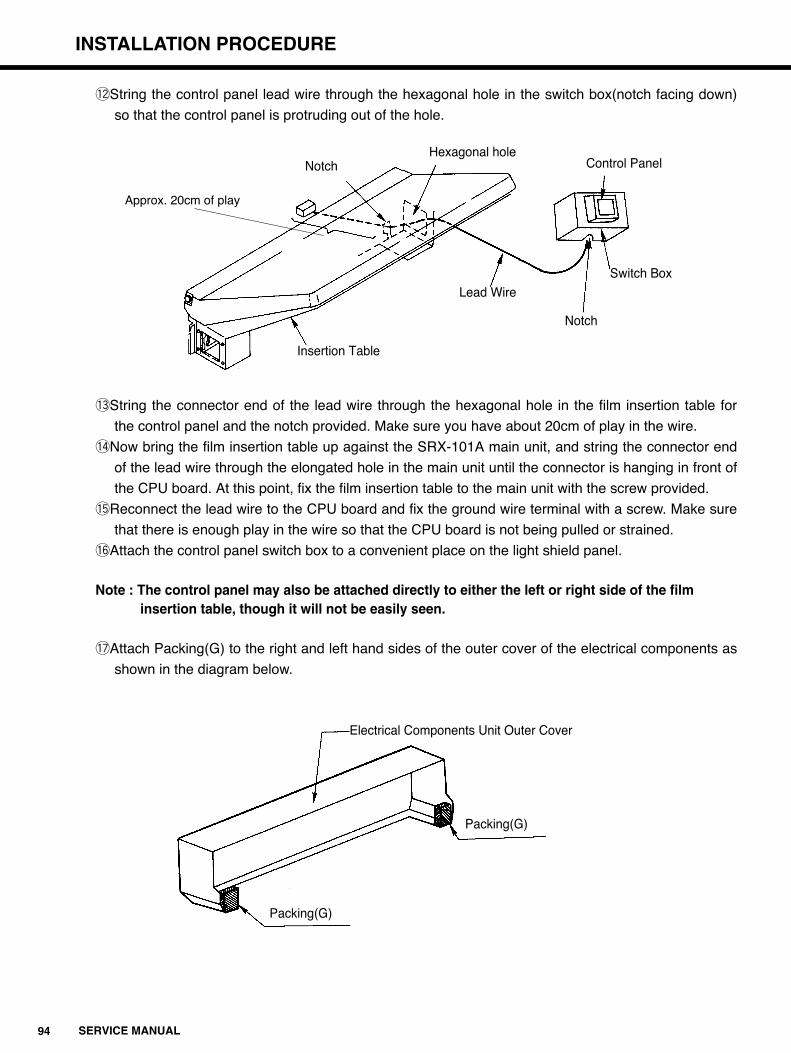
94 SERVICE MANUAL
INSTALLATION PROCEDURE
!2String the control panel lead wire through the hexagonal hole in the switch box(notch facing down)
so that the control panel is protruding out of the hole.
!3String the connector end of the lead wire through the hexagonal hole in the film insertion table for
the control panel and the notch provided. Make sure you have about 20cm of play in the wire.
!4Now bring the film insertion table up against the SRX-101A main unit, and string the connector end
of the lead wire through the elongated hole in the main unit until the connector is hanging in front of
the CPU board. At this point, fix the film insertion table to the main unit with the screw provided.
!5Reconnect the lead wire to the CPU board and fix the ground wire terminal with a screw. Make sure
that there is enough play in the wire so that the CPU board is not being pulled or strained.
!6Attach the control panel switch box to a convenient place on the light shield panel.
Note : The control panel may also be attached directly to either the left or right side of the film insertion table, though it will not be easily seen.
!7Attach Packing(G) to the right and left hand sides of the outer cover of the electrical components as
shown in the diagram below.
Insertion Table
Lead Wire
Notch
Switch Box
Control PanelHexagonal hole
Notch
Approx. 20cm of play
Electrical Components Unit Outer Cover
Packing(G)
Packing(G)

95SERVICE MANUAL
INSTALLATION PROCEDURE
!8Put the inner cover and outer cover of the electrical components unit back to the original position.
!9There will be an area uncovered by the outer cover between bottom of the components housing and
the bottom of the light shield. Cut a piece of Packing(D)[thickness 5mm] into a strip of 450mm long
and attach it to the bottom of the electrical components housing.
@0Attach the square-shaped Packing(F) to the left and right sides of the light shield panel.
(4 pieces in total)
@1Cut pieces of Packing(C) into two strips of 200mm long and attach them to the left and right sides of
the light shield panel around the electrical components unit cover.
SRX-101A Electrical Components Unit Outer Cover
Components Housing
450mm Strip of Packing(D)
Upper Light Shield
Right Light Shield
Lower Light Shield
Packing(F)
Main Unit Stand
(Do the same for the left side)
SRX-101A
Right Light Shield
Electrical Components OuterCover
Lower Light Shield
200mm Strips ofPacking(C)
Left Light Shield

96 SERVICE MANUAL
INSTALLATION PROCEDURE
@2Attach Packing(D)[thickness 10mm] around the opening in the partition and light shield panel. Attach
the packing only to the upper, left, and right sides of where the wall and light shield panel will meet.
@3Lower the insertion table side legs so that the SRX-101A is leveled. Taking special care of the unit's
left and right side position, move the processor up against the partition, and then level the unit once
again.
Notes : 1. Push the light shield up against the partition so that it is bowed slightly towards the darkroom.
This position will give the best light shielding results.2. If the unit cannot be leveled with only the adjustment bolt on the support, shim the support up
using material that will not change shape, like steel plate.
@4Attach the light shield rubber lining to cover the opening between floor and the bottom of the light
shield panel as below. Cut Packing(B)[thickness 20mm] into a block whose length will match the
rubber lining, and stick it to the rubber lining.
Packing(D)Darkroom Side
Film Insertion Table
Processing Tank Light Room Side
Wall
Light Shield Rubber Lining
Wall Light ShieldPanel
Packing(B)
Wall

97SERVICE MANUAL
INSTALLATION PROCEDURE
@5Attach the magnetic catch to the center for the Upper Light Shield.
@6Attach the steel plate to the film insertion table cover so that it hits the magnetic catch when the
cover is folded up. (See the diagram below)
@7Open(fold up) the film insertion table cover and make sure that the magnetic catch is strong enough
to hold it open while operating the SRX-101A.
@8Put back the top cover and make sure that the light shield is functioning properly from the darkroom
side.
Magnetic Catch
Light Shield Panel
Wall
Steel Plate
SRX-101A
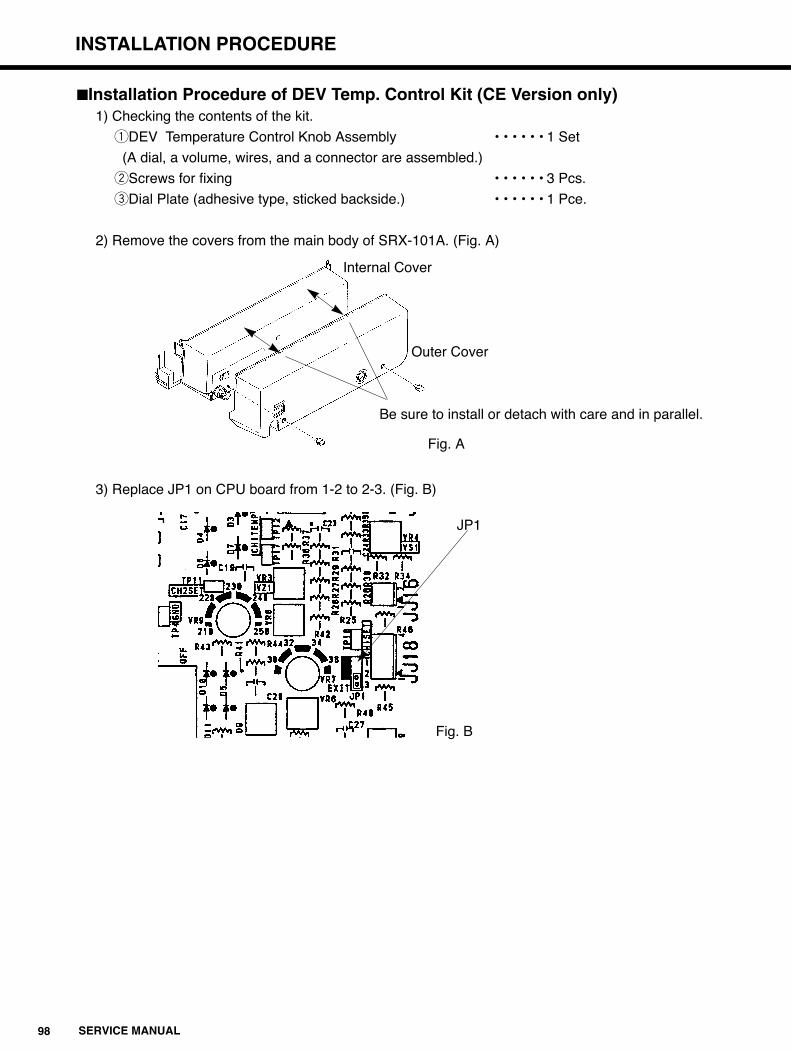
98 SERVICE MANUAL
INSTALLATION PROCEDURE
�Installation Procedure of DEV Temp. Control Kit (CE Version only)1) Checking the contents of the kit.
qDEV Temperature Control Knob Assembly • • • • • • 1 Set
(A dial, a volume, wires, and a connector are assembled.)
wScrews for fixing • • • • • • 3 Pcs.
eDial Plate (adhesive type, sticked backside.) • • • • • • 1 Pce.
2) Remove the covers from the main body of SRX-101A. (Fig. A)
3) Replace JP1 on CPU board from 1-2 to 2-3. (Fig. B)
Internal Cover
Outer Cover
Be sure to install or detach with care and in parallel.
Fig. A
Fig. B
JP1
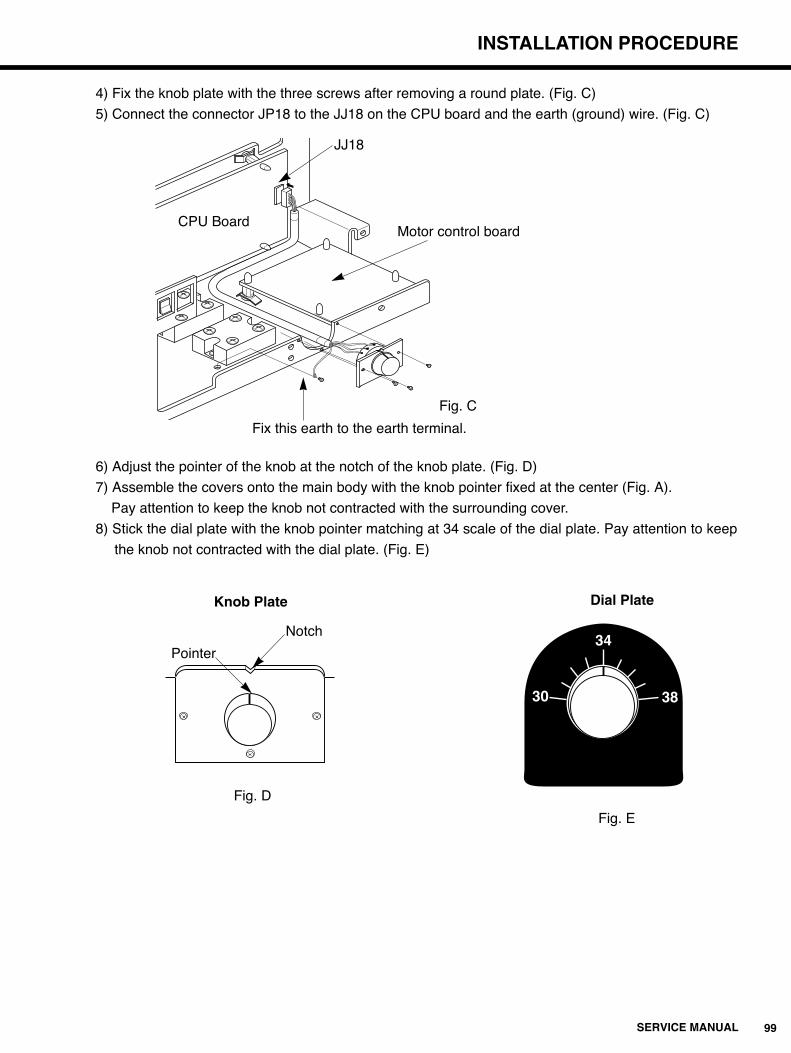
99SERVICE MANUAL
INSTALLATION PROCEDURE
4) Fix the knob plate with the three screws after removing a round plate. (Fig. C)
5) Connect the connector JP18 to the JJ18 on the CPU board and the earth (ground) wire. (Fig. C)
6) Adjust the pointer of the knob at the notch of the knob plate. (Fig. D)
7) Assemble the covers onto the main body with the knob pointer fixed at the center (Fig. A).
Pay attention to keep the knob not contracted with the surrounding cover.
8) Stick the dial plate with the knob pointer matching at 34 scale of the dial plate. Pay attention to keep
the knob not contracted with the dial plate. (Fig. E)
Fig. C
CPU Board
JJ18
Fix this earth to the earth terminal.
Dial Plate
Motor control board
Pointer
Notch
Knob Plate
Fig. E
Fig. D
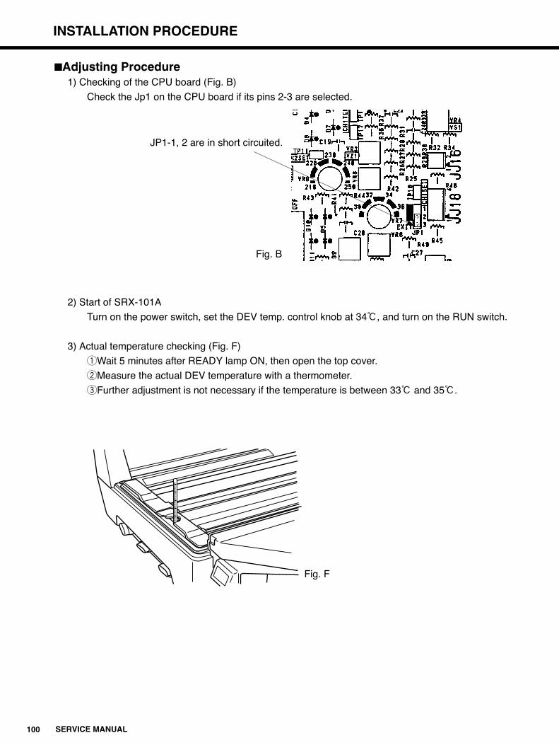
100 SERVICE MANUAL
INSTALLATION PROCEDURE
�Adjusting Procedure1) Checking of the CPU board (Fig. B)
Check the Jp1 on the CPU board if its pins 2-3 are selected.
2) Start of SRX-101A
Turn on the power switch, set the DEV temp. control knob at 34:, and turn on the RUN switch.
3) Actual temperature checking (Fig. F)
qWait 5 minutes after READY lamp ON, then open the top cover.
wMeasure the actual DEV temperature with a thermometer.
eFurther adjustment is not necessary if the temperature is between 33: and 35:.
JP1-1, 2 are in short circuited.
Fig. B
Fig. F

101SERVICE MANUAL
INSTALLATION PROCEDURE
4)When the actual temperature is not between 33: and 35:, proceed the Knob positionadjustment (Fig. G).qLoosen the set screw of the knob which locates just opposite of the pointer.
Pay attention not to move the volume shaft.
wSet the pointer at the measured temperature value.
eTighten the set screw of the knob with the volume shaft not moving.
Next, make the adjustment according to the temperature conditions as Case 1 and Case 2.
Case 1 : When the actual temperature is over 35:.
1)Cooling down of the DEV solution
Turn off RUN switch to wait the actual temperature becomes lower than 34:
In order to check the temperature, make DEV solution circulating.
(Turn off the RUN switch immediately after turning it on, the DEV solution circulates 2 minutes.)
2)Recheck
After turn off the RUN switch, set the dial at 34:, and turn on the RUN switch again.
Return to the step 3) Actual temperature checking.
Case 2 : When the actual temperature is under 33:.Make the above step 2) Recheck.
Fig. G

10511052-55030A
KONICA MEDICAL CORP.411 Newark Pompton Turnpike, Wayne, NJ 07470, U.S.A.TEL.973-633-1500
KONICA FRANCE S.A.Paris Nord II, 305 rue de la Belle Etoile, B.P. 50077, 95948 ROISSY C.D.G. CEDEX, FRANCETEL.1-4938-6550
KONICA CANADA INC.1329 Meyerside Drive, Mississauga, OntarioL5T 1C9, CANADATEL.905-670-7722
KONICA U.K. LTD.Plane Tree Crescent, Feltham, MiddlesexTW13 7HD, U.K.TEL.1-81-751-6121
KONICA EUROPE GMBHFriedrich-Bergius-Str. Gewerbegebiet,85662 Hohenbrunn, GERMANY TEL.8102-8040
KONICA AUSTRALIA PTY.LTD.22 Giffnock Avenue, North Ryde, N.S.W. 2113, AustraliaTEL.2-886-0333
9802TE(500)


