
Mechanical Disciplinary Research
Marissa Caldwell, Anya Godigamuwe, Valerie Miller,Yuka Narisako, Jimmy Weaver

Variable Refrigerant Flow Systems (VRF)
[James Weaver]

The Vapor Compression Cycle
Expansion Valve
Compressor
Evaporator Coil
Condenser Coil

Variable Refrigerant Flow/Volume Systems
Figure 2: VRV System in a tall building. Provided by Daikin Industries, Ltd.
A VRF System operates by sending
refrigerant between an outdoor and indoor
unit.
The outdoor unit houses the condenser and
compressor.
The indoor unit houses the evaporator.
Refrigerant is varied to each indoor unit
based on the desired load using electronic
expansion valves or pulse modulating
valves.
Heat Recovery is available through the
reuse of energy from superheated
refrigerant.
Goetzler, William. Variable Refrigerant Flow Systems. ASHRAE Journal. April 2007.

Advantages Vs. Disadvantages Advantages:
Lightweight and modular
Flexible Design
Minimal Ductwork
Individual Comfort Control
Energy Efficient – High Part Load
Efficiency
Disadvantages:
Initial Costs
Refrigerant Piping Concerns
Cold Climate Issues
Market Acceptance
Many Require a Dedicated Outdoor Air
System
Figure 3: Heat Recovery VRF System. Provided by ASHRAE Journal, April 2007.
Goetzler, William. Variable Refrigerant Flow Systems. ASHRAE Journal. April 2007.

Potential Project Benefits
Figure 4: Temperature distribution in a building. Provided by Daikin Industries, Ltd.
Figure 5: VRV system with 100% Outside Air Unit. Provided by Daikin Industries, Ltd.
A multi-purpose building can
benefit from space by space
comfort control.
Minimal Ductwork can provide
solutions to challenging space
and coordination issues.
Energy performance from a VRF
system can improve a building
operational costs.
Goetzler, William. Variable Refrigerant Flow Systems. ASHRAE Journal. April 2007.

Thermal Energy Storage
[Yuka Narisako]

Thermal Energy Storage – Definition Store unused energy when it is undesired and
release it when it is necessary to reduce energy waste.
http://www.calmac.com/products/icebank.asp

Thermal Energy Storage – Types of Systems Time/Consumption
based Peak shaving
Heating Hot water tanks in homes Thermal mass
Cooling Water pumped from dams Water storage units Ice storage units
http://www.calmac.com/products/icebank.asp

Thermal Energy Storage – Real World Example Nissan Technical Center
North America Inc. Farmington Hills, MI
Duquesne University Pittsburgh, PA Add ice making chiller and
ice storage unit
http://www.energystorageexchange.org/

Thermal Energy Storage – Possible Use for Project Reduce cooling load by installing small chiller
and ice storage unit Lower cost Reduce size of mechanical room Possibly provide cooling for future

Energy Recovery Ventilator (ERV)
[Valerie Miller]

[Energy Recovery Ventilator] – Definition Energy Recovery Ventilators (ERV’s) utilize
conditioned waste air energy to precondition outdoor air, by the use of a heat exchanger.
Heating and cooling All ERV’s transfer sensible heat (temperature);
some types transfer latent heat (humidity)
Space Airconditioning PLCSustainable Sources

[Energy Recovery Ventilator] – Types of Systems Thermal Wheel Plate to Plate Runaround Coil
Fastlane: Ventilation Equipment LimitedLive Building: Integrated Learning Centre

[Energy Recovery Ventilator] – Types of Systems Thermal Wheel
Enthalpy Wheel Wheel spins between exhaust
and outdoor air duct, transferring the heat from the hotter air to the cooler air
Sensible and Latent heat; transfers heat and moisture
Small cross-contamination Ducts must be close
Plate to Plate Runaround Coil
Fastlane: Ventilation Equipment LimitedLive Building: Integrated Learning Centre
Sacramental Municipal Utility District Energy Info. Library
Fastlane: Ventilation Equipment Limited

[Energy Recovery Ventilator] – Types of Systems Thermal Wheel Plate to Plate
Air streams pass through alternating plates
Air streams never come in contact; no cross-contamination
Ducts must be close Runaround Coil
Fastlane: Ventilation Equipment LimitedLive Building: Integrated Learning Centre
Fantronix Online Ventilation Solutions
Fastlane: Ventilation Equipment Limited

[Energy Recovery Ventilator] – Types of Systems Thermal Wheel Plate to Plate Runaround Coil
Coil’s containing a medium run through the exhaust system
No cross-contamination Ducts can be any
distance
Fastlane: Ventilation Equipment LimitedLive Building: Integrated Learning Centre
Fastlane: Ventilation Equipment Limited

[Energy Recovery Ventilator] – Types of Systems
Fastlane: Ventilation Equipment LimitedLive Building: Integrated Learning CentreTrane
Thermal Wheel
Plate to Plate Runaround Coil
0
10
20
30
40
50
60
70
80
90
100
Heat Exchanger Efficiency
HeatingCooling
Effi
cie
ncy (
%)

[Energy Recovery Ventilator] – Example McAllister Building
(2) enthalpy wheel ERV’s 73.7% and 71.4% effective <0.04% cross-contamination
OPP Commissioning Wikispaces

[Energy Recovery Ventilator] – Example Carnegie Mellon University's
Intelligent Workplace Enthalpy wheel Reduced heating load by 77%
James W. Meacham’s Spring 2003 Senior Thesis Grade School, Philadelphia, PA Enthalpy Wheel cost summary
showed a cost savings of ~$25,000 in the first year, a 4 day payback period
Installing an Enthalpy Wheel in new construction allows you to downsize equipment and save money up-front Florida school saved $25,000 up-
front by equipment downsizingProceedings of IMEC2006: 2006 ASME International Mechanical Engineering Congress and ExpositionAn FPL Technical Primer: Energy Recovery VentilationGreenheck: Energy Recovery Application Manual:
http://www.flickr.com/photos/32215181@N08/5521845253/in/photostream/
Greenheck: Energy Recovery Application Manual:

Earth-Coupled Systems
[Anya Godigamuwe]

Earth-Coupled Systems– Definition Using the near
constant temperature of the Earth to heat spaces in winter and to cool spaces in summer
Introduction to Geothermal Technologies / Egg & Howard

Earth-Coupled Systems– Types of Systems
Closed Loop
Introduction to Geothermal Technologies / Egg & Howard

Earth-Coupled Systems– Types of Systems
Open toReinjection
Introduction to Geothermal Technologies / Egg & Howard

Earth-Coupled Systems– Types of Systems
StandingColumn
Introduction to Geothermal Technologies / Egg & Howard

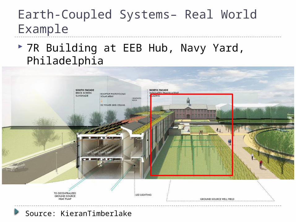
Earth-Coupled Systems– Real World Example 7R Building at EEB Hub, Navy Yard,
Philadelphia
Source: KieranTimberlake
Earth-Coupled Systems– Real World Example 7R Building at EEB Hub, Navy Yard,
Philadelphia
Source: KieranTimberlake

Earth-Coupled Systems– Possible Use for Project
Pros Cons
Could provide 80% heating/cooling needs
Short payoff period
Not suited for 24/7 cooling
Requires a large area of land
Introduction to Geothermal Technologies / Egg & Howard

Radiant Floor Heating
Marissa Caldwell

Radiant Floor Heating – Definition Supplies heat to the floor
from tubing or cables under the floor
Radiant Heat Transfer Heats from floor up Natural circulation
through convection
http://energy.gov/energysaver/articles/radiant-heating

Hydronic vs. Electric Hydronic
Uses pumps and valves to regulate flow based on design temps
Longer to heat up floor Requires a boiler
Electric Uses conduit to pass
electricity at night to heat the thermal mass, and radiate heat during the day

Radiant Floor Heating– Types of Systems Wet Installation
Tubing is placed within the concrete slab
Allows for the use of energy storage in the thermal mass
Dry Installation Plywood is placed on top of the
tubing It can be either sandwiched in or
the tubing is stapled to the underside of the flooring
http://energy.gov/energysaver/articles/radiant-heating

Radiant Floor Heating – Real World Example Herbert Jacobs House – Wisconsin
Wright 1st to use radiant floor heating in a US home
Hearst Tower – New York Radiant floor heating was added in their three-
story atrium to avoid heating unoccupied space California Academy of Sciences – California
35-foot-high museum space, reduced energy through heating by 10%
http://www.calacademy.org/academy/building/sustainable_design/

Radiant Floor Heating – Possible Use for Project This system is ideal for large spaces with high
ceilings Improved indoor air quality Inexpensive if the building already has a boiler Allows for open layouts
Thermal Dynamics of Radiant Floor Heating – Darren Cent


