
MCP2200USB 2.0 to UART Protocol Converter with GPIO
Features
Universal Serial Bus (USB)
• Supports full-speed USB (12 Mb/s)
• Implements USB protocol composite device CDC device for communications, configuration and I/O control
• 128 byte buffer to handle data throughput at any UART baud rate:
- 64 byte transmit
- 64 byte receive
• Fully configurable VID and PID assignments, and string descriptors
• Bus powered or self-powered
• USB 2.0 Compliant (certification #: TBD)
USB Driver and Software Support
• Uses standard Microsoft® Windows® drivers for Virtual Com Port (VCP):
- Windows XP(SP2 and later)/Vista/7
• Configuration utility for initial configuration
Universal Asynchronous Receiver/Transmitter (UART)
• Responds to SET LINE CODING commands to dynamically change baud rates
• Supports baud rates: 300-1000k
• Hardware flow control
• UART signal polarity option
General Purpose Input/Output (GPIO) Pins
• Eight (8) general purpose I/O pins
EEPROM
• 256 bytes of user EEPROM
Other
• USB activity LED outputs (TxLED and RxLED)
• SSPND output pin
• USBCFG output pin (indicates if requested current is allowed)
• Operating voltage: 3.0-5.5V
• Oscillator input: 12 MHz
• ESD protection > 4 kV HBM
• Industrial (I) Operating Temperature: -40°C to +85°C
Package Types
The device will be offered in the following packages:
• 20-lead QFN (5 x 5[mm])
• 20-lead SOIC
• 20-lead SSOP
2
MCP2200SOIC, SSOP
OSC2
OSC1
RST
1
2
3
4
20
19
18
17
VDD VSS
D+
D-
VUSB
GP7/TxLED 5 16 GP0/SSPND
GP6/RxLED 6 15
GP5 7 14 GP2
GP1/USBCFG
MCP22005x5 QFN*
GP6/RxLED
GP5
RST D-
VUSB
GP
3
GP0/SSPND
TX
RT
S
RX
GP1/USBCFG
OS
C2
OS
C1
VD
D
VS
S
GP7/TxLEDEP
20
1
19 18 17
3
4
15
14
13
12
6 7 8 9
21
13
12
11
CTS
RX
RTS
GP4 8
GP3 9TX 10
D+
16
GP4 GP25 11
CT
S
10
* Includes Exposed Thermal Pad (EP); see Table 1-1.
2010 Microchip Technology Inc. DS22228A-page 1

MCP2200
Block Diagram
UART Controller USB Protocol
ControllerUSB
Transceiver
3.3VLDO
Configuration and Control Registers
Osc Reset
Control
USB Clock
State Clock
GPIO
Baud Generator
VSS
VUSB
RSTVSS VDD
RX
TX
CTS
RTS
D+
D-
OSC1 OSC2
USB LEDs
TXLED/ RXLED/GP0
GP1GP2
GP3GP4
GP5
256 Byte EEPROM
GP7 GP6
DS22228A-page 2 2010 Microchip Technology Inc.
MCP2200
1.0 FUNCTIONAL DESCRIPTION
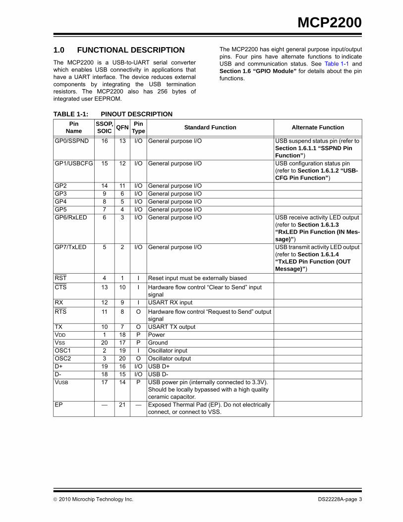
The MCP2200 is a USB-to-UART serial converterwhich enables USB connectivity in applications thathave a UART interface. The device reduces externalcomponents by integrating the USB terminationresistors. The MCP2200 also has 256 bytes ofintegrated user EEPROM.
The MCP2200 has eight general purpose input/outputpins. Four pins have alternate functions to indicateUSB and communication status. See Table 1-1 andSection 1.6 “GPIO Module” for details about the pinfunctions.
TABLE 1-1: PINOUT DESCRIPTION
Pin Name
SSOP,SOIC
QFNPin
TypeStandard Function Alternate Function
GP0/SSPND 16 13 I/O General purpose I/O USB suspend status pin (refer to Section 1.6.1.1 “SSPND Pin Function”)
GP1/USBCFG 15 12 I/O General purpose I/O USB configuration status pin (refer to Section 1.6.1.2 “USB-CFG Pin Function”)
GP2 14 11 I/O General purpose I/OGP3 9 6 I/O General purpose I/OGP4 8 5 I/O General purpose I/OGP5 7 4 I/O General purpose I/OGP6/RxLED 6 3 I/O General purpose I/O USB receive activity LED output
(refer to Section 1.6.1.3 “RxLED Pin Function (IN Mes-sage)”)
GP7/TxLED 5 2 I/O General purpose I/O USB transmit activity LED output (refer to Section 1.6.1.4 “TxLED Pin Function (OUT Message)”)
RST 4 1 I Reset input must be externally biased
CTS 13 10 I Hardware flow control “Clear to Send” input signal
RX 12 9 I USART RX input
RTS 11 8 O Hardware flow control “Request to Send” output signal
TX 10 7 O USART TX outputVDD 1 18 P PowerVSS 20 17 P GroundOSC1 2 19 I Oscillator inputOSC2 3 20 O Oscillator outputD+ 19 16 I/O USB D+D- 18 15 I/O USB D-VUSB 17 14 P USB power pin (internally connected to 3.3V).
Should be locally bypassed with a high quality ceramic capacitor.
EP — 21 — Exposed Thermal Pad (EP). Do not electrically connect, or connect to VSS.
2010 Microchip Technology Inc. DS22228A-page 3
MCP2200
1.1 Supported Operating Systems
Microsoft Windows XP(SP2 and later)/Vista/7operating systems are supported.
1.1.1 ENUMERATION
The MCP2200 will enumerate as a USB device afterPOR. The device enumerates as both a HumanInterface Device (HID) for I/O control, and a VCP.
1.1.1.1 HID
The MCP2200 enumerates as a HID so the device canbe configured and the I/O can be controlled. A DLL issupplied by Microchip that allows I/O control using acustom interface.
1.1.1.2 VCP
The VCP enumeration implements the USB-to-UARTdata translation.
1.2 Control Module
The control module is the heart of the MCP2200. Allother modules are tied together and controlled via thecontrol module. The control module manages the datatransfers between the USB and the UART, as well ascommand requests generated by the USB hostcontroller, and commands for controlling the function ofthe UART and I/O.
1.2.1 SERIAL INTERFACE
The control module interfaces to the UART and USBmodules.
1.2.2 INTERFACING TO THE DEVICE
The MCP2200 can be accessed for reading and writingvia USB host commands. The device cannot beaccessed and controlled via the UART interface.
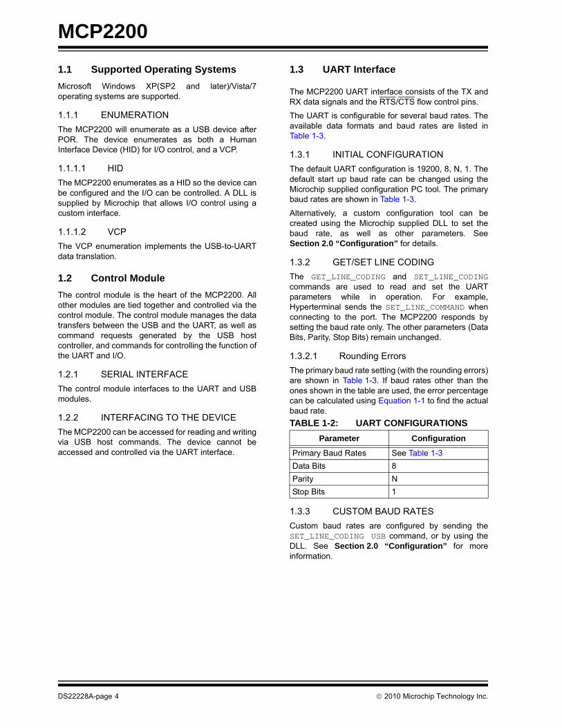
1.3 UART Interface
The MCP2200 UART interface consists of the TX andRX data signals and the RTS/CTS flow control pins.
The UART is configurable for several baud rates. Theavailable data formats and baud rates are listed inTable 1-3.
1.3.1 INITIAL CONFIGURATION
The default UART configuration is 19200, 8, N, 1. Thedefault start up baud rate can be changed using theMicrochip supplied configuration PC tool. The primarybaud rates are shown in Table 1-3.
Alternatively, a custom configuration tool can becreated using the Microchip supplied DLL to set thebaud rate, as well as other parameters. SeeSection 2.0 “Configuration” for details.
1.3.2 GET/SET LINE CODING
The GET_LINE_CODING and SET_LINE_CODINGcommands are used to read and set the UARTparameters while in operation. For example,Hyperterminal sends the SET_LINE_COMMAND whenconnecting to the port. The MCP2200 responds bysetting the baud rate only. The other parameters (DataBits, Parity, Stop Bits) remain unchanged.
1.3.2.1 Rounding Errors
The primary baud rate setting (with the rounding errors)are shown in Table 1-3. If baud rates other than theones shown in the table are used, the error percentagecan be calculated using Equation 1-1 to find the actualbaud rate.
1.3.3 CUSTOM BAUD RATES
Custom baud rates are configured by sending theSET_LINE_CODING USB command, or by using theDLL. See Section 2.0 “Configuration” for moreinformation.
TABLE 1-2: UART CONFIGURATIONS
Parameter Configuration
Primary Baud Rates See Table 1-3
Data Bits 8
Parity N
Stop Bits 1
DS22228A-page 4 2010 Microchip Technology Inc.

MCP2200
1.3.4 HARDWARE FLOW CONTROL
Hardware flow control uses the RTS and CTS pins asa handshake between two devices. The RTS pin ofone device is typically connected to the CTS of theother device.
RTS is an active low output which notifies the otherdevice when it can receive data by driving the pin low.The MCP2200 trip point for de-asserting RTS (high) is63 characters. This is one character short of “bufferfull”.
CTS is an active low input which is used to notify theMCP2200 when it can send data. The MCP2200 willcheck CTS just before loading and sending UART data.If the pin is asserted during a transfer, the transfer willcontinue. Refer to Figure 1-1.
1.3.4.1 Flow Control Disabled
The buffer pointer does not increment (or reset tozero) if the buffer is full. Therefore, if hardware flowcontrol is not enabled and an overflow occurs (i.e., 65unprocessed characters received), the new data over-writes the last position in the buffer.
FIGURE 1-1: RTS/CTS CONNECTIONS EXAMPLE
EQUATION 1-1: SOLVING FOR ACTUAL BAUD RATE
1.4 USB Protocol Controller
The USB controller in the MCP2200 is full-speed USB2.0 compliant.
• Composite device (CDC + HID):
- CDC: USB-to-UART communications
- HID: I/O control, EEPROM access and initial configuration
• 128 byte buffer to handle data throughput at any UART baud rate:
- 64 byte transmit
- 64 byte receive
• Fully configurable VID and PID assignments, and descriptors (stored on-chip)
• Bus powered or self-powered
1.4.1 DESCRIPTORS
The descriptors are stored in the MCP2200 duringconfiguration using the supplied PC interface.
1.4.2 SUSPEND AND RESUME
The USB Suspend and Resume signals are supportedfor power management of the MCP2200. The devicewill enter Suspend mode when suspend signaling isdetected on the bus.
The MCP2200 exits the Suspend mode when any ofthe following occur:
1. Resume signaling is detected or generated
2. A USB Reset signal is detected
3. A device Reset occurs
RTS RTS
CTS CTS
I am readyto receive
I’ll transmitif okay
I am readyto receive
I’ll transmitif okay
MCU MCP2200
ActualRate 12MHzint x
------------------=
Where:x 12MHz
DesiredBaud-----------------------------------=
TABLE 1-3: UART PRIMARY BAUD RATES
Desired Rate Actual rate % Error
300 300 0.00%
1200 1200 0.00%
2400 2400 0.00%
4800 4800 0.00%
9600 9600 0.00%
19200 19200 0.00%
38400 38339 0.16%
57600 57692 0.16%
115200 115385 0.16%
230400 230769 0.16%
460800 461538 0.16%
921600 923077 0.16%
2010 Microchip Technology Inc. DS22228A-page 5

MCP2200
1.5 USB Transceiver
The MCP2200 has a built-in, USB 2.0, full-speedtransceiver internally connected to the USB module.
The USB transceiver obtains power from the VUSB pin,which is internally connected to the 3.3V regulator. Thebest electrical signal quality is obtained when VUSB islocally bypassed with a high quality ceramic capacitor.
1.5.1 INTERNAL PULL-UP RESISTORS
The MCP2200 devices have built-in pull-up resistorsdesigned to meet the requirements for full-speed USB.
1.5.1.1 Bus Power Only
In Bus Power Only mode, all power for the applicationis drawn from the USB (Figure 1-2). This is effectivelythe simplest power method for the device.
In order to meet the inrush current requirements of theUSB 2.0 specifications, the total effective capacitanceappearing across VBUS and ground must be no morethan 10 µF. If not, some kind of inrush limiting isrequired. For more details, see Section 7.2.4 of the“Universal Serial Bus Specification”.
According to the USB 2.0 specification, all USB devicesmust also support a Low-Power Suspend mode. In theUSB Suspend mode, devices must consume no morethan 500 µA (or 2.5 mA for high powered devices thatare remote wake-up capable) from the 5V VBUS line ofthe USB cable.
The host signals the USB device to enter Suspendmode by stopping all USB traffic to that device for morethan 3 ms.
During USB Suspend mode, the D+ or D- pull-upresistor must remain active, which will consume someof the allowed suspend current budget (500 µA/2.5 mA).
FIGURE 1-2: BUS POWER ONLY
1.6 GPIO Module
The GPIO Module is a standard 8-bit I/O port.
1.6.1 CONFIGURABLE PIN FUNCTIONS
The pins can be configured as:
• GPIO – Individually configurable general purpose input or output
• SSPND – USB Suspend state
• USBCFG – Indicates USB configuration status
• RxLED – Indicates USB receive traffic
• TxLED – Indicates USB transmit traffic
1.6.1.1 SSPND Pin Function
The SSPND pin (if enabled) reflects the USB state(Suspend/Resume). The pin is active ‘low’ when theSuspend state has been issued by the USB host.Likewise, the pin drives ‘high’ after the Resume state isachieved.
This pin allows the application to go into Low Powermode when USB communication is suspended, andswitches to a full active state when USB activity isresumed.
1.6.1.2 USBCFG Pin Function
The USBCFG pin (if enabled) starts out ‘low’ duringpower-up or after Reset, and goes ‘high’ after thedevice successfully configures to the USB. The pin willgo ‘low’ when in Suspend mode and ‘high’ when theUSB resumes.
1.6.1.3 RxLED Pin Function (IN Message)
The ‘Rx’ in the pin name is in respect to the USB host.The RxLED pin is an indicator for USB ‘IN’ messages.
This pin will either pulse low for a period of time(configurable for ~100 ms or ~200 ms), or toggle to theopposite state for every message received(IN message) by the USB host. This allows theapplication to count messages or provide a visualindication of USB traffic.
1.6.1.4 TxLED Pin Function (OUT Message)
The ‘Tx’ in the pin name is in respect to the USB host.The TxLED pin is an indicator for USB ‘OUT’messages.
This pin will either pulse low for a period of time(configurable for ~100 ms or ~200 ms), or toggle to theopposite state for every message transmitted (OUTmessage) by the USB host. This allows the applicationto count messages or provide a visual indication ofUSB traffic.
VDD
VUSB
VSS
VBUS
DS22228A-page 6 2010 Microchip Technology Inc.

MCP2200
1.7 EEPROM Module
The EEPROM module is a 256 byte array of nonvolatilememory. The memory locations are accessed for read/write operations via USB host commands. Refer toSection 2.0 “Configuration” for details on accessingthe EEPROM.
The host should wait for the write cycle to complete andthen verify the write by reading the byte(s).
1.8 RESET/POR
1.8.1 RESET PIN
The RST pin provides a method for triggering anexternal Reset of the device. A Reset is generated byholding the pin low. These devices have a noise filter inthe reset path which detects and ignores small pulses.
1.8.2 POR
A Power-on Reset pulse is generated on-chipwhenever VDD rises above a certain threshold. Thisallows the device to start in the initialized state whenVDD is adequate for operation.
To take advantage of the POR circuitry, tie the RST pinthrough a resistor (1 kOhm to 10 kOhm) to VDD. Thiswill eliminate external RC components usually neededto create a Power-on Reset delay.
When the device starts normal operation (i.e., exits theReset condition), device operating parameters(voltage, frequency, temperature, etc.) must be met toensure operation. If these conditions are not achieved,the device must be held in Reset until the operatingconditions are met.
1.9 Oscillator
The input clock must be 12 MHz to provide the properfrequency for the USB module.
USB full-speed is nominally 12 Mb/s. The clock inputaccuracy is ±0.25% (2,500 ppm maximum).
FIGURE 1-3: QUARTZ CRYSTAL OPERATION
FIGURE 1-4: CERAMIC RESONATOR OPERATION
Quartz Crystal12 MHz
OSC1
OSC2RS(1)
RF(2)
MCP2200
Note 1: A series resistor (RS) may be requiredfor quartz crystals with high drive level.
2: The value of RF is typically between2 M to 10 M.
Example: muRata CSTCE12M0G15L
OSC1
OSC2
Resonator12 MHz
MCP2200
2010 Microchip Technology Inc. DS22228A-page 7

MCP2200
2.0 CONFIGURATION
The MCP2200 is configured by writing specialcommands using the HID interface. Configuration canbe achieved using the configuration utility provided byMicrochip. Alternatively, a custom utility can bedeveloped by using the DLL available on the MCP2200product page.
2.1 Configuration Utility
A configuration utility is provided by Microchip to allowthe user to configure the MCP2200 to custom defaults.The Configuration Utility (Figure 2-1) connects to thedevice’s HID interface where all of the configurablefeatures can be set.
2.2 Serial String
The MCP2200 is supplied from the factory with aserialized USB serial string.
TABLE 2-1: CONFIGURATION DESCRIPTIONS
Configuration Name Description
Vendor ID (0x04D8) The USB vendor identification assigned to Microchip by the USB consortium.
Product ID (0x00DF) Device ID assigned by Microchip. The device can be used “as-is”, or Microchip can assign a custom PID by request.
Baud Rate Sets the UART baud rate using a list of primary baud rates. See the UART section for details on setting non-primary baud rates.
IO Config Individually configures the I/O to inputs or outputs.
IO Default Individually configures the output default state for pins configured as outputs.
Tx/Rx LEDs Enables/disables the GP6 and GP7 pins to function as USB traffic indicators. Pins are active low when configured as traffic indicators.
Hardware Flow Control Enables/disables CTS and RTS flow control.
USBCFG Pin Enables/disables the GP1 pin as a USB configuration status indicator.
Suspend Pin Enables/disables the GP0 pin as a USB suspend status pin.
Invert Sense Enables/disables the UART lines states:
- Normal – Tx/Rx idle high; CTS/RTS active low
- Inverted – Tx/Rx idle low; CTS/RTS active high
Manufacturer String USB manufacturer string.
Product String USB product string.
DS22228A-page 8 2010 Microchip Technology Inc.

MCP2200
FIGURE 2-1: CONFIGURATION UTILITY
2010 Microchip Technology Inc. DS22228A-page 9

MCP2200
2.3 Simple Configuration and I/O DLL
A DLL is provided by Microchip to help the userdevelop a custom configurator. See the documentationon the MCP2200 product page for details onassociating the DLL with a Visual C++ project.
2.3.1 SIMPLE I/O DLL CALLS
The DLL provides the following functions to allowconfiguration of the device and control of the I/O.
2.3.1.1 Initialization
void InitMCP2200(VID, PID)bool IsConnected()
2.3.1.2 Configuration (only needs to be set once; stored in NVM)
bool ConfigureIOPins(mask)bool fnRxLED (On/Off, Toggle/Blink, 100/200mS)bool fnTxLED (On/Off, Toggle/Blink, 100/200mS)bool fnHardwareFlowControl (On/Off)bool fnUSBcfg(on/off)bool fnSuspend (on/off)bool SetBaudRate (baudrate)bool ConfigureAll (TRISmask, RxLED, TxLED, RxTGL, TxTGL, LEDX, FLOW, USBCFG, SSPND, BaudRate)
2.3.1.3 I/O Control
bool ClearPin(pinnumber)bool ReadPin(pinnumber)bool SetPort (portValue)bool ReadPort(*portValue)bool WriteEEPROM (Address, Data)bool ReadEEPROM (Address)
2.3.1.4 Summary
Summary:SimpleIOClass::InitMCP2200 (unsigned int VendorID, unsigned int ProductID)bool SimpleIOClass::ConfigureMCP2200 (unsigned char IOMap, unsigned long BaudRate, unsigned int RxLED,unsigned int TxLED,bool Hardware Flow Control, bool USBCFG pin function,bool Suspend pin function)bool SimpleIOClass::SetPin(unsigned int pin) bool SimpleIOClass::ClearPin(unsigned int pin) bool SimpleIOClass::ReadPin(unsigned int pin, unsigned int *returnvalue)bool SimpleIOClass::WritePort(unsigned int value)bool SimpleIOClass::ReadPort(unsigned int *returnvalue)
While ConfigureMCP2200 configures the device with one call, it may also be configured one parameter at a time:bool SimpleIOClass::fnRxLED (unsigned int mode)bool SimpleIOClass::fnTxLED (unsigned int mode)bool SimpleIOClass::fnHardwareFlowControl (unsigned int onOff)bool SimpleIOClass::fnUSBCFG (unsigned int onOff)bool SimpleIOClass::fnSuspend (unsigned int onOff)bool SimpleIOClass::fnSetBaudRate (unsigned long BaudRateParam)bool SimpleIOClass::ConfigureIO (unsigned char IOMap)
Constants:const unsigned int OFF = 0;const unsigned int ON = 1;const unsigned int TOGGLE = 3;const unsigned int BLINKSLOW = 4;const unsigned int BLINKFAST = 5;
2.3.1.5 InitMCP2200
SimpleIOClass::InitMCP2200 (unsigned int VendorID, unsigned int ProductID)
Configures the Simple IO class for a specific Vendor and product ID.
Parameters:Vendor ID - Assigned by USB IF (www.usb.org)
Product ID - Assigned by the Vendor ID Holder
Returns:none
Example: InitMCP2200 (0x04D8, 0x00DF);
2.3.1.6 ConfigureMCP2200
bool SimpleIOClass::ConfigureMCP2200 (unsigned char IOMap, unsigned long BaudRate, unsigned int RxLED,unsigned int TxLED,bool Hardware Flow Control, bool USBCFG pin function,bool Suspend pin function)
Configures the device's default baudrate, GPIO configuration and pin functions. Other functions set each parameter one at a time. This configures the part in one call.
Precondition:The Vendor and Product ID must have been specified by SimpleIOInit.
DS22228A-page 10 2010 Microchip Technology Inc.
MCP2200
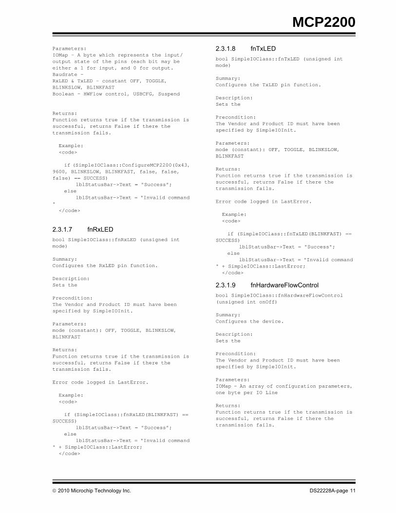
Parameters:IOMap - A byte which represents the input/output state of the pins (each bit may be either a 1 for input, and 0 for output.Baudrate - RxLED & TxLED - constant OFF, TOGGLE, BLINKSLOW, BLINKFASTBoolean - HWFlow control, USBCFG, Suspend
Returns:Function returns true if the transmission is successful, returns False if there the transmission fails.
Example: <code>
if (SimpleIOClass::ConfigureMCP2200(0x43, 9600, BLINKSLOW, BLINKFAST, false, false, false) == SUCCESS)
lblStatusBar->Text = "Success";else
lblStatusBar->Text = "Invalid command " </code>
2.3.1.7 fnRxLED
bool SimpleIOClass::fnRxLED (unsigned int mode)
Summary:Configures the RxLED pin function.
Description:Sets the
Precondition:The Vendor and Product ID must have been specified by SimpleIOInit.
Parameters:mode (constant): OFF, TOGGLE, BLINKSLOW, BLINKFAST
Returns:Function returns true if the transmission is successful, returns False if there the transmission fails.
Error code logged in LastError.
Example: <code>
if (SimpleIOClass::fnRxLED(BLINKFAST) == SUCCESS)
lblStatusBar->Text = "Success";else
lblStatusBar->Text = "Invalid command " + SimpleIOClass::LastError; </code>
2.3.1.8 fnTxLED
bool SimpleIOClass::fnTxLED (unsigned int mode)
Summary:Configures the TxLED pin function.
Description:Sets the
Precondition:The Vendor and Product ID must have been specified by SimpleIOInit.
Parameters:mode (constant): OFF, TOGGLE, BLINKSLOW, BLINKFAST
Returns:Function returns true if the transmission is successful, returns False if there the transmission fails.
Error code logged in LastError.
Example: <code>
if (SimpleIOClass::fnTxLED(BLINKFAST) == SUCCESS)
lblStatusBar->Text = "Success";else
lblStatusBar->Text = "Invalid command " + SimpleIOClass::LastError; </code>
2.3.1.9 fnHardwareFlowControl
bool SimpleIOClass::fnHardwareFlowControl (unsigned int onOff)
Summary:Configures the device.
Description:Sets the
Precondition:The Vendor and Product ID must have been specified by SimpleIOInit.
Parameters:IOMap - An array of configuration parameters, one byte per IO Line
Returns:Function returns true if the transmission is successful, returns False if there the transmission fails.
2010 Microchip Technology Inc. DS22228A-page 11
MCP2200
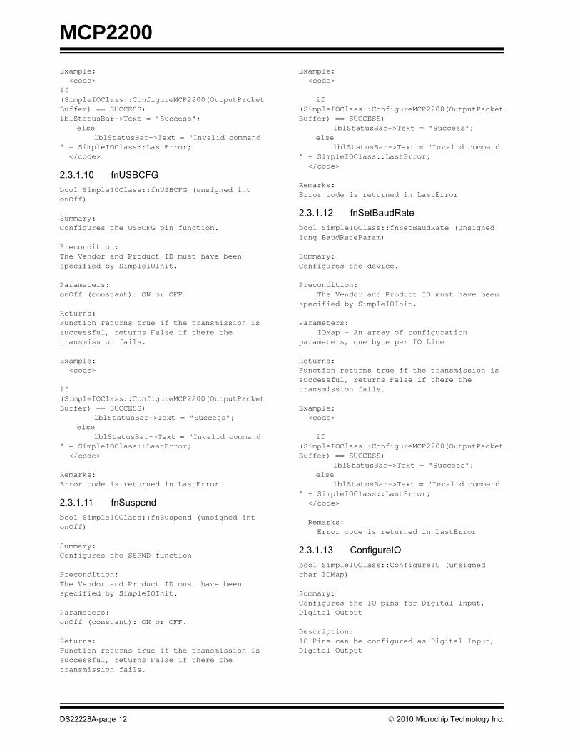
Example: <code>if (SimpleIOClass::ConfigureMCP2200(OutputPacketBuffer) == SUCCESS)lblStatusBar->Text = "Success";
elselblStatusBar->Text = "Invalid command
" + SimpleIOClass::LastError; </code>
2.3.1.10 fnUSBCFG
bool SimpleIOClass::fnUSBCFG (unsigned int onOff)
Summary:Configures the USBCFG pin function.
Precondition:The Vendor and Product ID must have been specified by SimpleIOInit.
Parameters:onOff (constant): ON or OFF.
Returns:Function returns true if the transmission is successful, returns False if there the transmission fails.
Example: <code>
if (SimpleIOClass::ConfigureMCP2200(OutputPacketBuffer) == SUCCESS)
lblStatusBar->Text = "Success";else
lblStatusBar->Text = "Invalid command " + SimpleIOClass::LastError; </code>
Remarks:Error code is returned in LastError
2.3.1.11 fnSuspend
bool SimpleIOClass::fnSuspend (unsigned int onOff)
Summary:Configures the SSPND function
Precondition:The Vendor and Product ID must have been specified by SimpleIOInit.
Parameters:onOff (constant): ON or OFF.
Returns:Function returns true if the transmission is successful, returns False if there the transmission fails.
Example: <code>
if (SimpleIOClass::ConfigureMCP2200(OutputPacketBuffer) == SUCCESS)
lblStatusBar->Text = "Success";else
lblStatusBar->Text = "Invalid command " + SimpleIOClass::LastError; </code>
Remarks:Error code is returned in LastError
2.3.1.12 fnSetBaudRate
bool SimpleIOClass::fnSetBaudRate (unsigned long BaudRateParam)
Summary:Configures the device.
Precondition: The Vendor and Product ID must have been specified by SimpleIOInit.
Parameters: IOMap - An array of configuration parameters, one byte per IO Line
Returns:Function returns true if the transmission is successful, returns False if there the transmission fails.
Example: <code>
if (SimpleIOClass::ConfigureMCP2200(OutputPacketBuffer) == SUCCESS)
lblStatusBar->Text = "Success";else
lblStatusBar->Text = "Invalid command " + SimpleIOClass::LastError; </code>
Remarks: Error code is returned in LastError
2.3.1.13 ConfigureIO
bool SimpleIOClass::ConfigureIO (unsigned char IOMap)
Summary:Configures the IO pins for Digital Input, Digital Output
Description:IO Pins can be configured as Digital Input, Digital Output
DS22228A-page 12 2010 Microchip Technology Inc.

MCP2200
Precondition:The Vendor and Product ID must have been specified by SimpleIOInit.
Parameters:IOMap - one byte, with each bit corresponding to each GP pin. 0 for output, 1 for input.
Returns:Function returns true if the transmission is successful, returns False if there the transmission fails.
Example: <code>
if (SimpleIOClass::ConfigureGPIO(OutputPacketBuffer) == SUCCESS)
lblStatusBar->Text = "Success";else
lblStatusBar->Text = "Invalid command " + SimpleIOClass::LastError; </code>
2.3.1.14 SetPin
bool SimpleIOClass::SetPin(unsigned int pin)
Summary:Sets the specified pin.
Description:Sets the specified pin to one.
Precondition:Must have previously been configured as an output via a ConfigureGPIO call.
Parameters:pin - The pin number to set (0-7)
Returns:Function returns true if the transmission is successful, returns False if there the transmission fails.
Example: <code>
if (SimpleIOClass::SetPin (2)){
lblStatusBar->Text = "Success";}else
lblStatusBar->Text = "Invalid command " + SimpleIOClass::LastError; </code>
Remarks:none
2.3.1.15 ClearPin
bool SimpleIOClass::ClearPin(unsigned int pin)
Summary:Clears the specified pin.
Description:Sets the specified pin to zero.
Precondition:Must have previously been configured as an output via a ConfigureGPIO call.
Parameters:pin - The pin number to set (0-7)
Returns:Function returns true if the transmission is successful, returns False if there the transmission fails.
Example: <code>
if (SimpleIOClass::ClearPin (2)){
lblStatusBar->Text = "Success";}else
lblStatusBar->Text = "Invalid command " + SimpleIOClass::LastError; </code>
Remarks:none
2.3.1.16 ReadPin
bool SimpleIOClass::ReadPin(unsigned int pin, unsigned int *returnvalue)
Summary: Reads the specified pin.
Description:Reads the specified pin and returns the value in returnvalue. If the pin has been configured as Digital Input, the return value will be either 0 or 1. If the pin has been configured as Analog Input, the pin will be read by the ADC and return a 10 bit value, right justified.
Precondition:Must have previously been configured as an input via a ConfigureGPIO call.
Parameters:pin - The pin number to set (0-7)returnvalue - the value read on the pin (0 or 1)
2010 Microchip Technology Inc. DS22228A-page 13

MCP2200
Returns: true if the pin was successfully read. false if the pin was not read (not configued as an input).
Example: <code> unsigned int rv;
if (SimpleIOClass::ReadGPIOn (0, &rv)){
lblStatusBar->Text = "Success";}else
lblStatusBar->Text = "Invalid command " + SimpleIOClass::LastError; </code>
2.3.1.17 WritePort
bool SimpleIOClass::WritePort(unsigned int portValue)
Summary:Writes a value to the GPIO port.
Description:Writes the GPIO port. This provides a means to write all pins at once instead of one-at-a-time.
Precondition:Must have previously been configured as an output via a ConfigureGPIO call.
Parameters:portValue - Byte value to set on the port.
Returns:Function returns true if the transmission is successfulreturns False if there the transmission fails.
Example: <code>
if (SimpleIOClass::WritePort (0x5A)){
lblStatusBar->Text = "Success";}else
lblStatusBar->Text = "Invalid command " + SimpleIOClass::LastError; </code>
Remarks:Pins configured for output returns the current state of the port.
Pins configured as input read as zero.
2.3.1.18 ReadPort
bool SimpleIOClass::ReadPort(unsigned int *returnvalue)
Summary: Reads the GPIO port as digital input.
Description:Reads the GPIO port and returns the value in returnvalue. This provides a means to read all pins at once instead of one-at-a-time.
Precondition:Must have previously been configured as an input via a ConfigureGPIO call.
Parameters:returnvalue - the value read on the port.
Returns: Function returns true if the read is successful returns False if there the transmission fails.
Example: <code>unsigned int rv;
if (SimpleIOClass::ReadGPIOPort (&rv)){
lblStatusBar->Text = "Success";}else
lblStatusBar->Text = "Invalid command " + SimpleIOClass::LastError; </code>
Remarks:Pins configured for output returns the
current state of the port.Pins configured as input read as zero.
DS22228A-page 14 2010 Microchip Technology Inc.

MCP2200
3.0 ELECTRICAL CHARACTERISTICS
Absolute Maximum Ratings (†)
Ambient temperature under bias......................................................................................................... -40°C to +85°C
Storage temperature ........................................................................................................................ -65°C to +150°C
Voltage on VDD with respect to VSS, PIC18F ..................................................................................... -0.3V to +6.0V
Voltage on VDD with respect to VSS, PIC18LF ................................................................................... -0.3V to +4.0V
Voltage on MCLR with respect to Vss ................................................................................................. -0.3V to +9.0V
Voltage on VUSB pin with respect to VSS ............................................................................................ -0.3V to +4.0V
Voltage on D+ and D- pins with respect to VSS ...................................................................... -0.3V to (VUSB + 0.3V)
Voltage on all other pins with respect to VSS ........................................................................... -0.3V to (VDD + 0.3V)
Total power dissipation(1) ............................................................................................................................... 800 mW
Maximum current out of VSS pin ...................................................................................................................... 95 mA
Maximum current into VDD pin ......................................................................................................................... 95 mA
Clamp current, IK (VPIN < 0 or VPIN > VDD)20 mA
Maximum output current sunk by any I/O pin.................................................................................................... 25 mA
Maximum output current sourced by any I/O pin .............................................................................................. 25 mA
Maximum current sunk by all ports ................................................................................................................... 90 mA
Maximum current sourced by all ports ............................................................................................................. 90 mA
Note 1: Power dissipation is calculated as follows: PDIS = VDD x {IDD – IOH} + {(VDD – VOH) x IOH} + (VOl x IOL).
2: VUSB must always be VDD + 0.3V
† NOTICE: Stresses above those listed under “Absolute Maximum Ratings” may cause permanent damage to the device. This is a stress rating only and functional operation of the device at those or any other conditions above those indicated in the operation listings of this specification is not implied. Exposure above maximum rating conditions for extended periods may affect device reliability.
2010 Microchip Technology Inc. DS22228A-page 15

MCP2200
3.1 DC CHARACTERISTICS
DC CharacteristicsOperating Conditions (unless otherwise indicated):3.0V VDD 5.5V at -40C TA +85C (I-Temp)
Param No.
Characteristic Sym Min Typ Max Units Conditions
D001 Supply Voltage VDD 3.0 — 5.5 V
Power-on Reset Release Voltage
VPOR 1.6 V
Power-on Reset Rearm Voltage
0.8 V
D003 VDD Rise Rate to Ensure Power-on Reset
SVDD 0.05 — — V/ms Design guidance onlyNot tested
D004 Supply Current IDD
VDD = 3.0V — 10 12 mA FOSC = 12 MHz,(330 nF on VUSB)VDD = 5.0V — 13 15 mA
D005 Standby current IDDS — 9 — µA
Input Low-Voltage
D031 Schmitt Trigger (GPIO)VIL
— — 0.2 VDD
V3.0V VDD 5.5V
TTL (CTS pin) — — 0.8 4.5V VDD 5.5V
Input High-Voltage
D041 Schmitt Trigger (GPIO)VIH
0.8 VDD — VDDV
3.0V VDD 5.5V
TTL (RTS pin) 2.0 — VDD 4.5V VDD 5.5V
Input Leakage Current
D060GPIO, CTS
IIL— ±50 ±100
nAVSS VPIN VDD, pin at Hi-Z
RST ±50 ±200
OSC1 ±50 ±100
Output Low-Voltage
D080 GPIO VOL — — 0.6 V IOL = 8.0 mA, VDD = 5.0V
— — 0.6 IOL = 6.0 mA, VDD = 3.3V
Output High-Voltage
D090 GPIO VOH VDD – 0.7 — — V IOH = -3.5 mA, VDD = 5.0V
VDD – 0.7 — — IOH = -3.0 mA, VDD = 3.3V
Capacitive Loading Specs on Output Pins
D101 OSC2 COSC2 — — 15 pF Note 1
D102 GPIO CIO — — 50 pF Note 1
Note 1: This parameter is characterized, but not tested.
DS22228A-page 16 2010 Microchip Technology Inc.

MCP2200
FIGURE 3-1: POR AND POR REARM WITH SLOW RISING VDD
TABLE 3-1: USB MODULE SPECIFICATIONS
DC CharacteristicsOperating Conditions (unless otherwise indicated):3.0V VDD 5.5V at -40C TA +85C (I-Temp)
Param No.
Characteristic Sym Min Typ Max Units Conditions
D313 USB Voltage VUSB 3.0 — 3.6 V Voltage on VUSB pin must be in this range for proper USB operation
D314 Input Leakage on Pin IIL — — ± 1 μA VSS VPIN VDD pin athigh-impedance
D315 Input Low Voltage for USB Buffer
VILUSB — — 0.8 V For VUSB range
D316 Input High Voltage for USB Buffer
VIHUSB 2.0 — — V For VUSB range
D318 Differential Input Sensitivity
VDIFS — — 0.2 V The difference between D+ and D- must exceed this value while VCM is met
D319 Differential Common Mode Range
VCM 0.8 — 2.5 V
D320 Driver Output Impedance(1)
ZOUT 28 — 44
D321 Voltage Output Low VOL 0.0 — 0.3 V 1.5 kload connected to 3.6V
D322 Voltage Output High VOH 2.8 — 3.6 V 1.5 kload connected to ground
Note 1: The D+ and D- signal lines have been built-in impedance matching resistors. No external resistors, capacitors or magnetic components are necessary on the D+/D- signal paths between the MCP2200 family device and the USB cable.
VDD
VPORVPORR
VSS
VSS
NPOR(1)
TPOR(3)
POR REARM
Note 1: When NPOR is low, the device is held in Reset.
2: TPOR 1 s typical.
3: TVLOW 2.7 s typical.
TVLOW(2)
2010 Microchip Technology Inc. DS22228A-page 17

MCP2200
TABLE 3-2: THERMAL CONSIDERATIONSStandard Operating Conditions (unless otherwise stated)Operating temperature -40C TA +85C (I-Temp)
ParamNo.
Sym Characteristic Typ Units Conditions
TH01 θJA Thermal Resistance Junction to Ambient
85.2 C/W 20-pin SOIC package
108.1 C/W 20-pin SSOP package
TBD C/W 20-pin QFN 5x5mm package
TH02 θJC Thermal Resistance Junction to Case
24 C/W 20-pin SOIC package
24 C/W 20-pin SSOP package
24 C/W 20-pin QFN 6x6mm package
TH03 TJMAX Maximum Junction Temperature 150 CTH04 PD Power Dissipation — W PD = PINTERNAL + PI/O
TH05 PINTERNAL Internal Power Dissipation — W PINTERNAL = IDD x VDD(1)
TH06 PI/O I/O Power Dissipation — W PI/O = (IOL * VOL) + (IOH * (VDD – VOH))
TH07 PDER Derated Power — W PDER = PDMAX (TJ - TA)/θJA(2,3)
Legend: TBD = To Be Determined.
Note 1: IDD is the current to run the chip alone without driving any load on the output pins.
2: TA = Ambient Temperature.
3: TJ = Junction Temperature.
DS22228A-page 18 2010 Microchip Technology Inc.
MCP2200
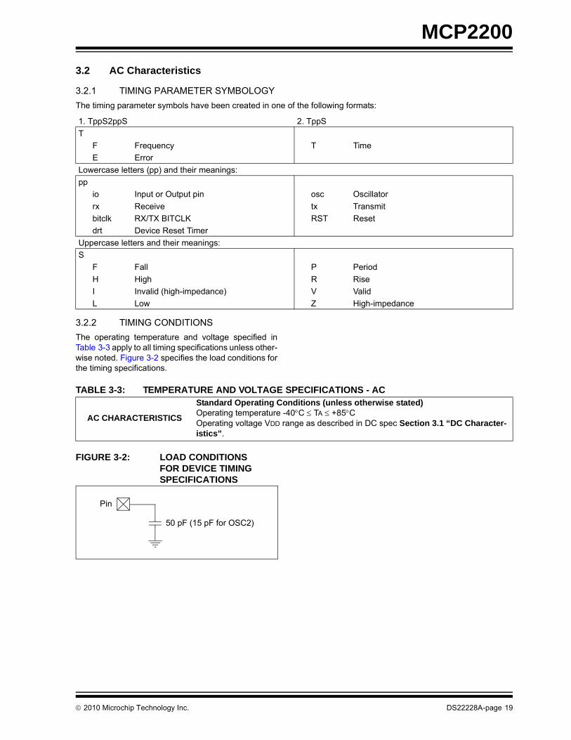
3.2 AC Characteristics
3.2.1 TIMING PARAMETER SYMBOLOGY
The timing parameter symbols have been created in one of the following formats:
3.2.2 TIMING CONDITIONS
The operating temperature and voltage specified inTable 3-3 apply to all timing specifications unless other-wise noted. Figure 3-2 specifies the load conditions forthe timing specifications.
TABLE 3-3: TEMPERATURE AND VOLTAGE SPECIFICATIONS - AC
FIGURE 3-2: LOAD CONDITIONS FOR DEVICE TIMING SPECIFICATIONS
1. TppS2ppS 2. TppS
T
F Frequency T Time
E Error
Lowercase letters (pp) and their meanings:
pp
io Input or Output pin osc Oscillator
rx Receive tx Transmit
bitclk RX/TX BITCLK RST Reset
drt Device Reset Timer
Uppercase letters and their meanings:
S
F Fall P Period
H High R Rise
I Invalid (high-impedance) V Valid
L Low Z High-impedance
AC CHARACTERISTICS
Standard Operating Conditions (unless otherwise stated)Operating temperature -40C TA +85COperating voltage VDD range as described in DC spec Section 3.1 “DC Character-istics”.
50 pF (15 pF for OSC2)
Pin
2010 Microchip Technology Inc. DS22228A-page 19
MCP2200
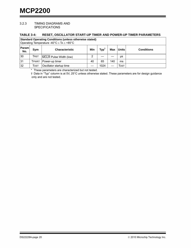
3.2.3 TIMING DIAGRAMS AND SPECIFICATIONS
TABLE 3-4: RESET, OSCILLATOR START-UP TIMER AND POWER-UP TIMER PARAMETERS
Standard Operating Conditions (unless otherwise stated)Operating Temperature -40°C TA +85°C
Param No.
Sym Characteristic Min Typ† Max Units Conditions
30 TRST MCLR Pulse Width (low) 2 — — μs
31 TPWRT Power-up timer 40 65 140 ms
32 TOST Oscillator startup time — 1024 — TOST
* These parameters are characterized but not tested.† Data in “Typ” column is at 5V, 25°C unless otherwise stated. These parameters are for design guidance only and are not tested.
DS22228A-page 20 2010 Microchip Technology Inc.

MCP2200
4.0 PACKAGING INFORMATION
4.1 Package Marking Information
Legend: XX...X Customer-specific informationY Year code (last digit of calendar year)YY Year code (last 2 digits of calendar year)WW Week code (week of January 1 is week ‘01’)NNN Alphanumeric traceability code Pb-free JEDEC designator for Matte Tin (Sn)* This package is Pb-free. The Pb-free JEDEC designator ( )
can be found on the outer packaging for this package.
Note: In the event the full Microchip part number cannot be marked on one line, it willbe carried over to the next line, thus limiting the number of availablecharacters for customer-specific information.
3e
3e
20-Lead SOIC Example:
XXXXXXXXXXXXXXXXXXXXXXXXXXXX
YYWWNNN
20-Lead QFN Example
XXXXXXXXXXXXXXXXX
YWWNNN
MCP2200I/MQ^^
10042563e
20-Lead SSOP Example:
XXXXXXXXXXXXXXI/SO^^
1004256
MCP2200
XXXXXXXXXXXXXXXXXXXXXX
YYWWNNN
^3̂e
I/SS^^1004256
MCP22003e
2010 Microchip Technology Inc. DS22228A-page 21

MCP2200
20-Lead Plastic Quad Flat, No Lead Package (MQ) – 5x5x0.9 mm Body [QFN]
Note: For the most current package drawings, please see the Microchip Packaging Specification located at http://www.microchip.com/packaging
Microchip Technology Drawing C04-120A
DS22228A-page 22 2010 Microchip Technology Inc.

MCP2200
Note: For the most current package drawings, please see the Microchip Packaging Specification located at http://www.microchip.com/packaging
2010 Microchip Technology Inc. DS22228A-page 23

MCP2200
���������� ��������� ��������� ��������������� ��!"#
$� ��%�� ������ �!"�����# $�% �&"� �'��� ���(�)"&�'"!&�) �����& #�*�&����&� ���&�� #��� ���� +������%����&�,�����& ��!&���-� ��' �!���!�����#�.��#����&�����"# �'��#�%��!�������&�"!���!�����#�%��!�������&�"!���!�!�������&� $� #����/�''� ��!�# ��� ��' �!���������#�&�� �������� �����.�0���/��
1�,2 1�!�����' �!������� �� &������� $��&� ��" �!��*��*�&��"&�&�� ���� !��.32 � % � �� ���' �!���(�"!"�����*�&��"&�&�� ���� (�%�����%��'�&����"��! !������
$� �% 3���&� �'�!&��"�� �&���4�� �#��*���!(�� �! �! �&� �������������4������� ��%���&��������& #��&��&&255***�'����������'5��4�����
6��&! ��77��.�.����' �!����7�'�&! ��8 89� ��:
8"') ���%����! 8 ����&�� �����1�,9 �����; ���& � < < ��=/���# #����4�� �����4� !! �� ���/ < <�&��#�%%��+ �� ���� < ��-�9 �����>�#&� . ���-��1�,���# #����4�� �>�#&� .� ��/��1�,9 �����7 ��&� � ������1�,,��'% ��?�&�����@ � ���/ < ���/3��&�7 ��&� 7 ���� < ����3��&���& 7� ������.33��&����� � �A < �A7 �#�����4� !! � ���� < ��--7 �#�>�#&� ) ��-� < ��/����#����%&����� ��� � /A < �/A���#����%&����� �1�&&�' � /A < �/A
β
D
EE1
eb
1 2 3
NOTE 1
A
A1
A2
hh
c
L1
L
φ
α
N
�������� � �������� ���*��� ,�����1
DS22228A-page 24 2010 Microchip Technology Inc.

MCP2200
Note: For the most current package drawings, please see the Microchip Packaging Specification located at http://www.microchip.com/packaging
2010 Microchip Technology Inc. DS22228A-page 25

MCP2200
���������� ���&'��(������� �����������)������� ���#
$� ��%�� ������ �!"�����# $�% �&"� �'��� ���(�)"&�'"!&�) �����& #�*�&����&� ���&�� #��� ���� ��' �!���!�����#�.��#����&�����"# �'��#�%��!�������&�"!���!�����#�%��!�������&�"!���!�!�������&� $� #������''� ��!�# �-� ��' �!���������#�&�� �������� �����.�0���/��
1�,2 1�!�����' �!������� �� &������� $��&� ��" �!��*��*�&��"&�&�� ���� !��.32 � % � �� ���' �!���(�"!"�����*�&��"&�&�� ���� (�%�����%��'�&����"��! !������
$� �% 3���&� �'�!&��"�� �&���4�� �#��*���!(�� �! �! �&� �������������4������� ��%���&��������& #��&��&&255***�'����������'5��4�����
6��&! ��77��.�.����' �!����7�'�&! ��8 89� ��:
8"') ���%����! 8 ����&�� ��=/�1�,9 �����; ���& � < < �������# #����4�� �����4� !! �� ��=/ ���/ ���/�&��#�%%� �� ���/ < <9 �����>�#&� . ���� ���� �������# #����4�� �>�#&� .� /��� /�-� /�=�9 �����7 ��&� � =��� ���� ��/�3��&�7 ��&� 7 ��// ���/ ���/3��&���& 7� ���/��.37 �#�����4� !! � ���� < ���/3��&����� � �A �A �A7 �#�>�#&� ) ���� < ��-�
φ
LL1
A2c
eb
A1
A
1 2
NOTE 1
E1
E
D
N
�������� � �������� ���*��� ,�����1
DS22228A-page 26 2010 Microchip Technology Inc.

MCP2200
Note: For the most current package drawings, please see the Microchip Packaging Specification located at http://www.microchip.com/packaging
2010 Microchip Technology Inc. DS22228A-page 27

MCP2200
NOTES:
DS22228A-page 28 2010 Microchip Technology Inc.

MCP2200
APPENDIX A: REVISION HISTORY
Revision A (March 2010)
• Original Release of this Document.
2010 Microchip Technology Inc. DS22228A-page 29

MCP2200
NOTES:
DS22228A-page 30 2010 Microchip Technology Inc.

MCP2200
PRODUCT IDENTIFICATION SYSTEM
To order or obtain information, e.g., on pricing or delivery, refer to the factory or the listed sales office.
PART NO. X /XX
PackageTemperatureRange
Device
Device MCP2200: USB-to-UART serial converterMCP2200T: USB-to-UART serial converter (Tape and Reel)
Temperature Range I = -40C to +85C (Industrial)
Package MQ = Plastic Quad Flat, No Lead Package 5x5x0.9 mm Body (QFN), 20-Lead
SO = Plastic Small Outline - Wide, 7.50 mm Body (SO),20-Lead
SS = Plastic Shrink Small Outline - 5.30 mm Body (SS)20-Lead
Examples:
a) MCP2200- I/MQ: Industrial temperature, 20LD QFN Package.
b) MCP2200T- I/MQ: Tape and Reel, Industrial temperature, 20LD QFN Package.
a) MCP2200- I/SO: Industrial temperature, 20LD SOIC Package.
b) MCP2200T- I/SO: Tape and Reel, Industrial temperature, 20LD SOIC Package.
a) MCP2200- I/SS: Industrial temperature, 20LD SSOP Package.
b) MCP2200T- I/SS: Tape and Reel, Industrial temperature, 20LD SSOP Package.
2010 Microchip Technology Inc. DS22228A-page 31

MCP2200
NOTES:
DS22228A-page 32 2010 Microchip Technology Inc.

Note the following details of the code protection feature on Microchip devices:
• Microchip products meet the specification contained in their particular Microchip Data Sheet.
• Microchip believes that its family of products is one of the most secure families of its kind on the market today, when used in the intended manner and under normal conditions.
• There are dishonest and possibly illegal methods used to breach the code protection feature. All of these methods, to our knowledge, require using the Microchip products in a manner outside the operating specifications contained in Microchip’s Data Sheets. Most likely, the person doing so is engaged in theft of intellectual property.
• Microchip is willing to work with the customer who is concerned about the integrity of their code.
• Neither Microchip nor any other semiconductor manufacturer can guarantee the security of their code. Code protection does not mean that we are guaranteeing the product as “unbreakable.”
Code protection is constantly evolving. We at Microchip are committed to continuously improving the code protection features of ourproducts. Attempts to break Microchip’s code protection feature may be a violation of the Digital Millennium Copyright Act. If such actsallow unauthorized access to your software or other copyrighted work, you may have a right to sue for relief under that Act.
Information contained in this publication regarding deviceapplications and the like is provided only for your convenienceand may be superseded by updates. It is your responsibility toensure that your application meets with your specifications.MICROCHIP MAKES NO REPRESENTATIONS ORWARRANTIES OF ANY KIND WHETHER EXPRESS ORIMPLIED, WRITTEN OR ORAL, STATUTORY OROTHERWISE, RELATED TO THE INFORMATION,INCLUDING BUT NOT LIMITED TO ITS CONDITION,QUALITY, PERFORMANCE, MERCHANTABILITY ORFITNESS FOR PURPOSE. Microchip disclaims all liabilityarising from this information and its use. Use of Microchipdevices in life support and/or safety applications is entirely atthe buyer’s risk, and the buyer agrees to defend, indemnify andhold harmless Microchip from any and all damages, claims,suits, or expenses resulting from such use. No licenses areconveyed, implicitly or otherwise, under any Microchipintellectual property rights.
2010 Microchip Technology Inc.
Trademarks
The Microchip name and logo, the Microchip logo, dsPIC, KEELOQ, KEELOQ logo, MPLAB, PIC, PICmicro, PICSTART, PIC32 logo, rfPIC and UNI/O are registered trademarks of Microchip Technology Incorporated in the U.S.A. and other countries.
FilterLab, Hampshire, HI-TECH C, Linear Active Thermistor, MXDEV, MXLAB, SEEVAL and The Embedded Control Solutions Company are registered trademarks of Microchip Technology Incorporated in the U.S.A.
Analog-for-the-Digital Age, Application Maestro, CodeGuard, dsPICDEM, dsPICDEM.net, dsPICworks, dsSPEAK, ECAN, ECONOMONITOR, FanSense, HI-TIDE, In-Circuit Serial Programming, ICSP, Mindi, MiWi, MPASM, MPLAB Certified logo, MPLIB, MPLINK, mTouch, Octopus, Omniscient Code Generation, PICC, PICC-18, PICDEM, PICDEM.net, PICkit, PICtail, REAL ICE, rfLAB, Select Mode, Total Endurance, TSHARC, UniWinDriver, WiperLock and ZENA are trademarks of Microchip Technology Incorporated in the U.S.A. and other countries.
SQTP is a service mark of Microchip Technology Incorporated in the U.S.A.
All other trademarks mentioned herein are property of their respective companies.
© 2010, Microchip Technology Incorporated, Printed in the U.S.A., All Rights Reserved.
Printed on recycled paper.
ISBN: 978-1-60932-051-5
DS22228A-page 33
Microchip received ISO/TS-16949:2002 certification for its worldwide headquarters, design and wafer fabrication facilities in Chandler and Tempe, Arizona; Gresham, Oregon and design centers in California and India. The Company’s quality system processes and procedures are for its PIC® MCUs and dsPIC® DSCs, KEELOQ® code hopping devices, Serial EEPROMs, microperipherals, nonvolatile memory and analog products. In addition, Microchip’s quality system for the design and manufacture of development systems is ISO 9001:2000 certified.

DS22228A-page 34 2010 Microchip Technology Inc.
AMERICASCorporate Office2355 West Chandler Blvd.Chandler, AZ 85224-6199Tel: 480-792-7200 Fax: 480-792-7277Technical Support: http://support.microchip.comWeb Address: www.microchip.com
AtlantaDuluth, GA Tel: 678-957-9614 Fax: 678-957-1455
BostonWestborough, MA Tel: 774-760-0087 Fax: 774-760-0088
ChicagoItasca, IL Tel: 630-285-0071 Fax: 630-285-0075
ClevelandIndependence, OH Tel: 216-447-0464 Fax: 216-447-0643
DallasAddison, TX Tel: 972-818-7423 Fax: 972-818-2924
DetroitFarmington Hills, MI Tel: 248-538-2250Fax: 248-538-2260
KokomoKokomo, IN Tel: 765-864-8360Fax: 765-864-8387
Los AngelesMission Viejo, CA Tel: 949-462-9523 Fax: 949-462-9608
Santa ClaraSanta Clara, CA Tel: 408-961-6444Fax: 408-961-6445
TorontoMississauga, Ontario, CanadaTel: 905-673-0699 Fax: 905-673-6509
ASIA/PACIFICAsia Pacific OfficeSuites 3707-14, 37th FloorTower 6, The GatewayHarbour City, KowloonHong KongTel: 852-2401-1200Fax: 852-2401-3431
Australia - SydneyTel: 61-2-9868-6733Fax: 61-2-9868-6755
China - BeijingTel: 86-10-8528-2100 Fax: 86-10-8528-2104
China - ChengduTel: 86-28-8665-5511Fax: 86-28-8665-7889
China - ChongqingTel: 86-23-8980-9588Fax: 86-23-8980-9500
China - Hong Kong SARTel: 852-2401-1200 Fax: 852-2401-3431
China - NanjingTel: 86-25-8473-2460Fax: 86-25-8473-2470
China - QingdaoTel: 86-532-8502-7355Fax: 86-532-8502-7205
China - ShanghaiTel: 86-21-5407-5533 Fax: 86-21-5407-5066
China - ShenyangTel: 86-24-2334-2829Fax: 86-24-2334-2393
China - ShenzhenTel: 86-755-8203-2660 Fax: 86-755-8203-1760
China - WuhanTel: 86-27-5980-5300Fax: 86-27-5980-5118
China - XianTel: 86-29-8833-7252Fax: 86-29-8833-7256
China - XiamenTel: 86-592-2388138 Fax: 86-592-2388130
China - ZhuhaiTel: 86-756-3210040 Fax: 86-756-3210049
ASIA/PACIFICIndia - BangaloreTel: 91-80-3090-4444 Fax: 91-80-3090-4123
India - New DelhiTel: 91-11-4160-8631Fax: 91-11-4160-8632
India - PuneTel: 91-20-2566-1512Fax: 91-20-2566-1513
Japan - YokohamaTel: 81-45-471- 6166 Fax: 81-45-471-6122
Korea - DaeguTel: 82-53-744-4301Fax: 82-53-744-4302
Korea - SeoulTel: 82-2-554-7200Fax: 82-2-558-5932 or 82-2-558-5934
Malaysia - Kuala LumpurTel: 60-3-6201-9857Fax: 60-3-6201-9859
Malaysia - PenangTel: 60-4-227-8870Fax: 60-4-227-4068
Philippines - ManilaTel: 63-2-634-9065Fax: 63-2-634-9069
SingaporeTel: 65-6334-8870Fax: 65-6334-8850
Taiwan - Hsin ChuTel: 886-3-6578-300Fax: 886-3-6578-370
Taiwan - KaohsiungTel: 886-7-536-4818Fax: 886-7-536-4803
Taiwan - TaipeiTel: 886-2-2500-6610 Fax: 886-2-2508-0102
Thailand - BangkokTel: 66-2-694-1351Fax: 66-2-694-1350
EUROPEAustria - WelsTel: 43-7242-2244-39Fax: 43-7242-2244-393Denmark - CopenhagenTel: 45-4450-2828 Fax: 45-4485-2829
France - ParisTel: 33-1-69-53-63-20 Fax: 33-1-69-30-90-79
Germany - MunichTel: 49-89-627-144-0 Fax: 49-89-627-144-44
Italy - Milan Tel: 39-0331-742611 Fax: 39-0331-466781
Netherlands - DrunenTel: 31-416-690399 Fax: 31-416-690340
Spain - MadridTel: 34-91-708-08-90Fax: 34-91-708-08-91
UK - WokinghamTel: 44-118-921-5869Fax: 44-118-921-5820
WORLDWIDE SALES AND SERVICE
01/05/10


