
1
Materials in high-temperaturesuperconducting cables
Dag Willénnkt cables
Autonomous University of Barcelona16 April 2008
2
Contents• Background on superconductivity• Materials in HTS cables• Cost – an industrial estimation• Example: The HTS Triax™ Energy Cable• Applications of HTS cables
3
Background on superconductivity
4
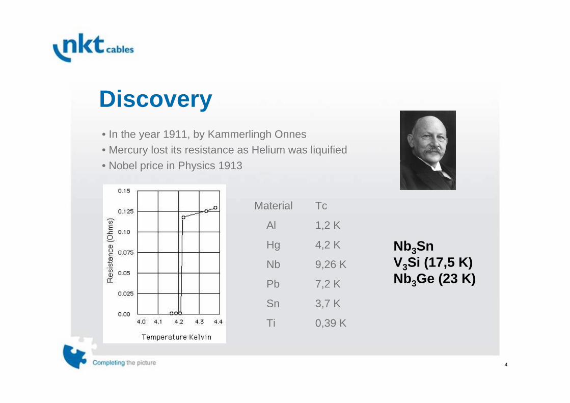
Discovery• In the year 1911, by Kammerlingh Onnes• Mercury lost its resistance as Helium was liquified• Nobel price in Physics 1913
Nb3SnV3Si (17,5 K)Nb3Ge (23 K)
Material Tc
Al 1,2 K
Hg 4,2 K
Nb 9,26 K
Pb 7,2 K
Sn 3,7 K
Ti 0,39 K

5
Development
K r i t i s k t e m p e r a t u r ( K e lv i n )
N b 3 SnN bH g
B i - 2 2 2 3
Y B C O
T l B a C a C u O
0
2 5
5 0
7 5
1 0 0
1 2 5
1 5 0
1 9 0 0 1 9 2 0 1 9 4 0 1 9 6 0 1 9 8 0 2 0 0 0Å rs ta l
HgBaCaCuO (133 K)
K r i t i s k t e m p e r a t u r ( K e lv i n )
N b 3 SnN bH g
B i - 2 2 2 3
Y B C O
T l B a C a C u O
0
2 5
5 0
7 5
1 0 0
1 2 5
1 5 0
1 9 0 0 1 9 2 0 1 9 4 0 1 9 6 0 1 9 8 0 2 0 0 0Å rs ta l
HgBaCaCuO (133 K)
year
Critical temperature[K]
J. Georg Bednorz and K. Alexander Müeller, IBM Zürich, La-Cu-Oxide, HTS ~30 K, 1986, Nobel price physics 1987
Paul Chu, Univ. Houston, YBCO, 1987, ~90 K

6
February 1995…
7
Materials in HTS cables
8
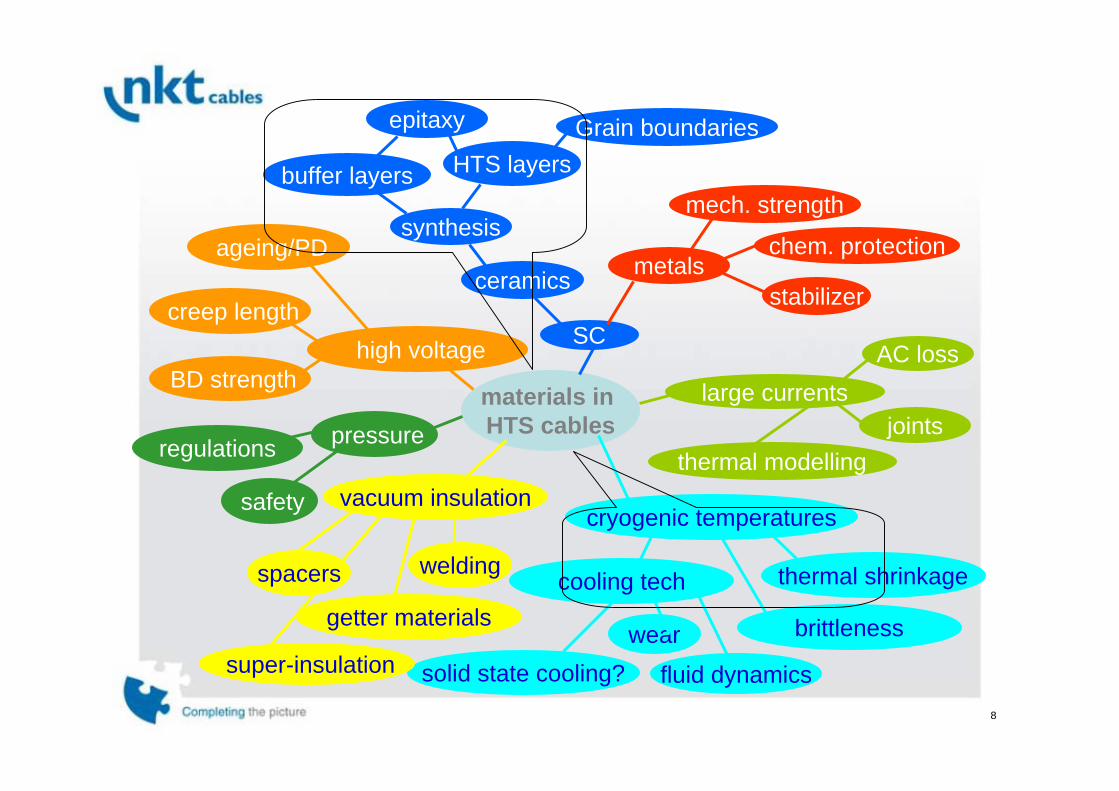
materials in HTS cables
SC
ceramics metalssynthesis
buffer layers HTS layersGrain boundaries
mech. strength
chem. protection
stabilizer
large currents
epitaxy
AC loss
jointsthermal modelling
cryogenic temperatures
thermal shrinkage
brittleness
cooling tech
wearsolid state cooling?
vacuum insulation
welding
getter materials
super-insulation fluid dynamics
spacers
pressureregulations
safety
high voltageBD strength
creep length
ageing/PD

9
Synthesis – 1G HTS
0.3 mm
4.5 mm
10
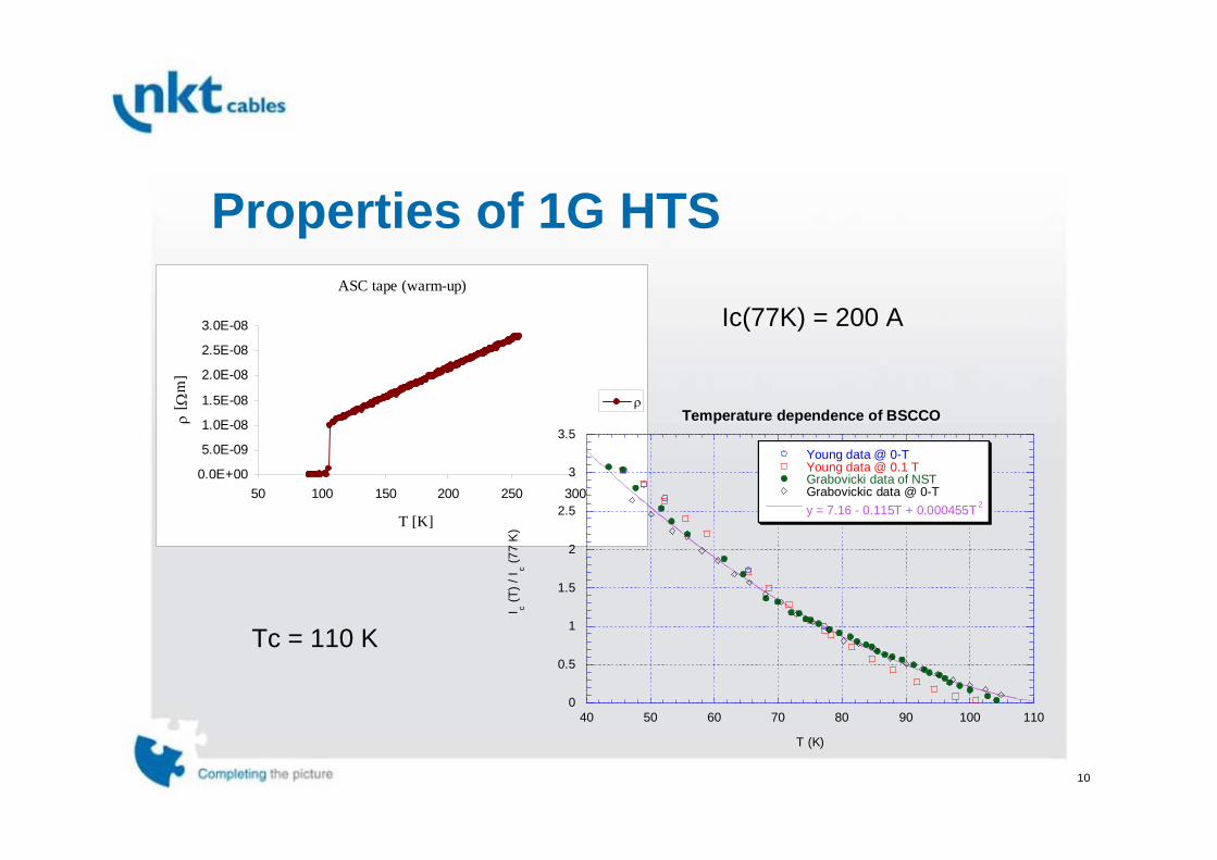
Properties of 1G HTSASC tape (warm-up)
0.0E+00
5.0E-09
1.0E-08
1.5E-08
2.0E-08
2.5E-08
3.0E-08
50 100 150 200 250 300
T [K]
ρ [ Ω
m]
ρ
0
0.5
1
1.5
2
2.5
3
3.5
40 50 60 70 80 90 100 110
Temperature dependence of BSCCO
Young data @ 0-TYoung data @ 0.1 TGrabovicki data of NSTGrabovickic data @ 0-Ty = 7.16 - 0.115T + 0.000455T 2
I c (T) /
I c (77
K)
T (K)
Ic(77K) = 200 A
Tc = 110 K

11
Synthesis – 2G HTS
Pilot HTS – SuperPower Inc.
Example:
HTS Layer by Metal Organic Chemical Vapor Deposition (MOCVD)
Example:
Buffer Layer by Ion Beam Assisted Deposition (IBAD)
12
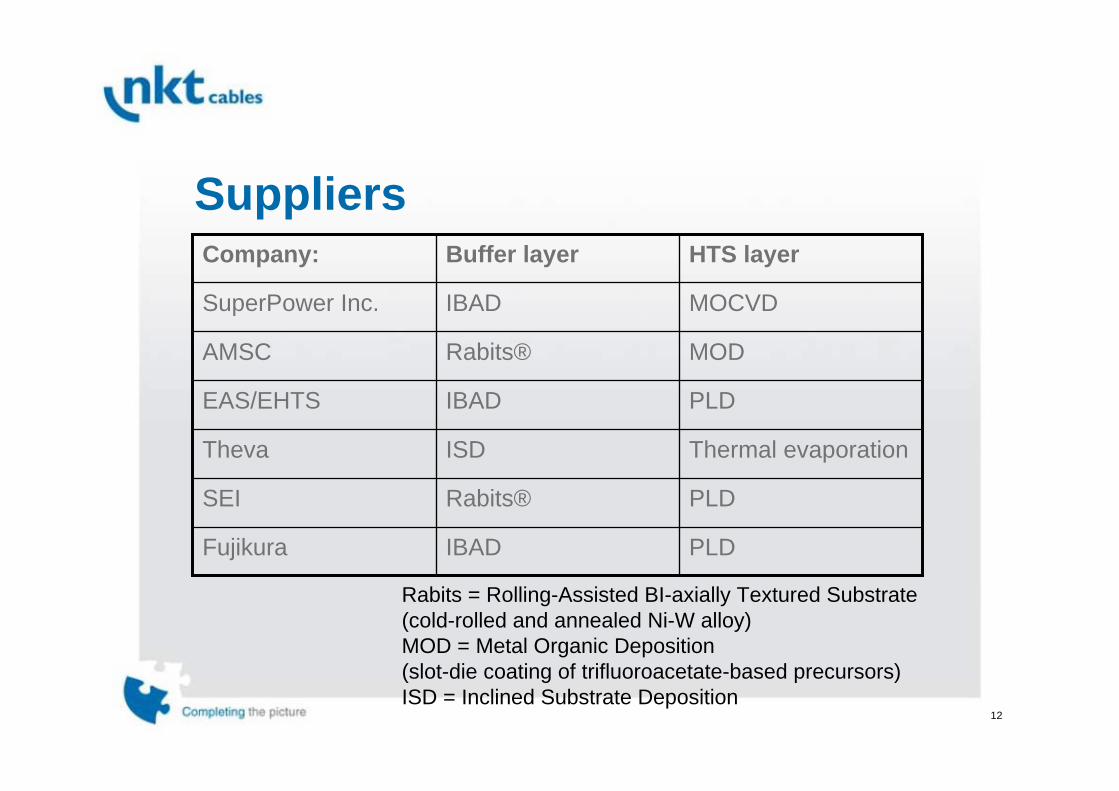
Suppliers
PLDIBADFujikura
PLDRabits®SEI
Thermal evaporationISDTheva
PLDIBADEAS/EHTS
MODRabits®AMSC
MOCVDIBADSuperPower Inc.
HTS layerBuffer layerCompany:
Rabits = Rolling-Assisted BI-axially Textured Substrate (cold-rolled and annealed Ni-W alloy)MOD = Metal Organic Deposition(slot-die coating of trifluoroacetate-based precursors)ISD = Inclined Substrate Deposition

13
Status, 2G
10 100 1000Length (meters)
100
1000
Crit
ical
cur
rent
s.f.
77K
(A/c
m-w
idth
)
Shortsamples
10,000 A-m
50,000
500,000
100,000
1,000,000
2006 GoalDOE
Target
10 100 1000Length (meters)
100
1000
Crit
ical
cur
rent
s.f.
77K
(A/c
m-w
idth
)
Shortsamples
10 100 1000Length (meters)
100
1000
Crit
ical
cur
rent
s.f.
77K
(A/c
m-w
idth
)
Shortsamples
10,000 A-m
50,000
500,000
100,000
1,000,000
2006 GoalDOE
TargetHTS cablereq.
14
Cost –an industrial estimation

15
Materials costs
Examples from 2005, USD
USD/kg
0
0,5
1
1,5
2
2,5
3
3,5
PE Pb Al Cu
USD/kg
16
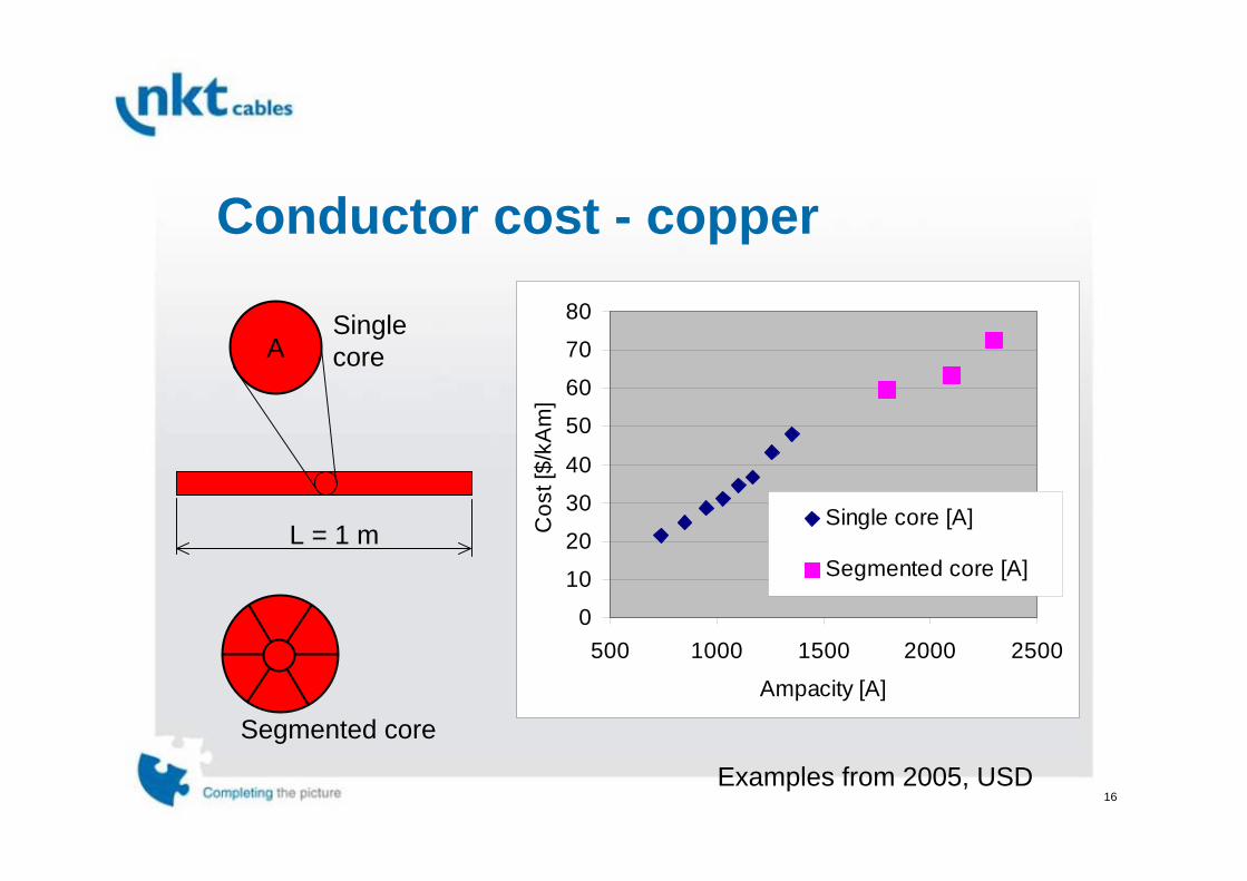
Conductor cost - copper
Examples from 2005, USD
0
10
20
30
40
50
60
70
80
500 1000 1500 2000 2500
Ampacity [A]
Cos
t [$/
kAm
]Single core [A]
Segmented core [A]
A
L = 1 m
A
Segmented core
Singlecore

17
1G cost
Examples from 2005, USD
Brass (Cu + Zn)
Solder (Sn + Pb)Sheath (Ag-alloy) Matrix (Ag)
HTS filaments (BSCCO)
18
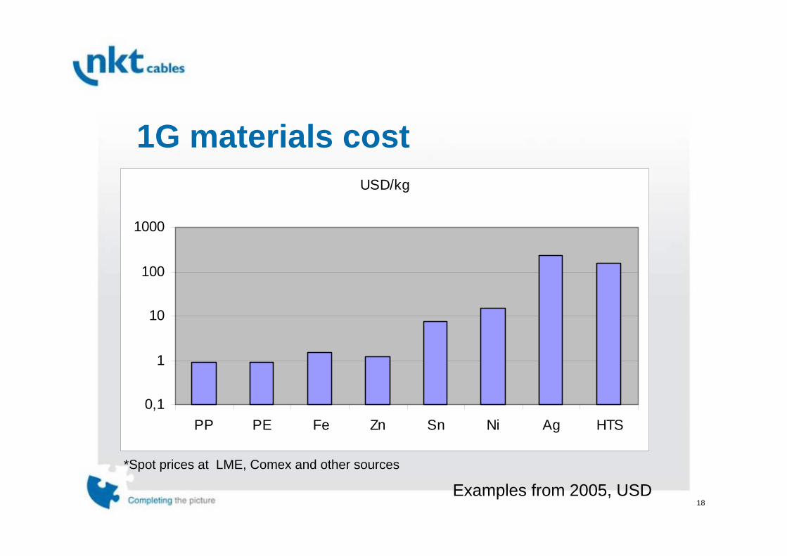
1G materials cost
Examples from 2005, USD*Spot prices at LME, Comex and other sources
USD/kg
0,1
1
10
100
1000
PP PE Fe Zn Sn Ni Ag HTS
19
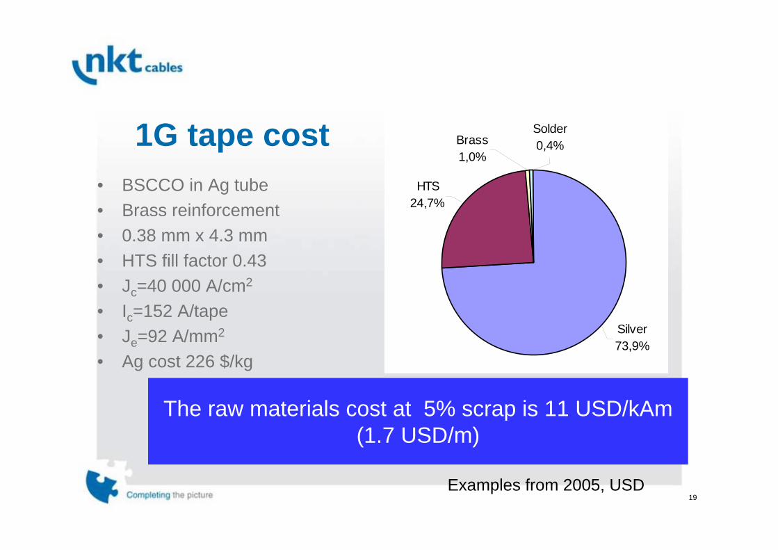
1G tape cost
Examples from 2005, USD
• BSCCO in Ag tube• Brass reinforcement• 0.38 mm x 4.3 mm• HTS fill factor 0.43• Jc=40 000 A/cm2
• Ic=152 A/tape• Je=92 A/mm2
• Ag cost 226 $/kg
The raw materials cost at 5% scrap is 11 USD/kAm(1.7 USD/m)
Silver73,9%
Solder0,4%Brass
1,0%
HTS24,7%
20
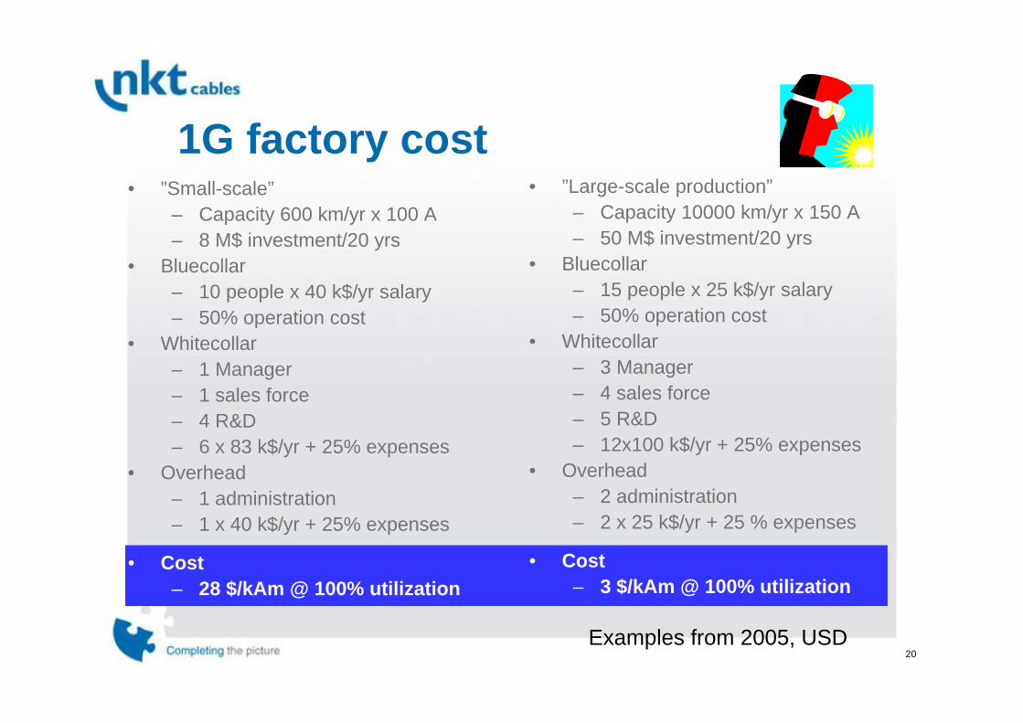
1G factory cost
Examples from 2005, USD
• ”Small-scale”– Capacity 600 km/yr x 100 A– 8 M$ investment/20 yrs
• Bluecollar– 10 people x 40 k$/yr salary– 50% operation cost
• Whitecollar– 1 Manager– 1 sales force– 4 R&D– 6 x 83 k$/yr + 25% expenses
• Overhead– 1 administration– 1 x 40 k$/yr + 25% expenses
• Cost– 28 $/kAm @ 100% utilization
• ”Large-scale production”– Capacity 10000 km/yr x 150 A– 50 M$ investment/20 yrs
• Bluecollar– 15 people x 25 k$/yr salary– 50% operation cost
• Whitecollar– 3 Manager– 4 sales force– 5 R&D– 12x100 k$/yr + 25% expenses
• Overhead– 2 administration– 2 x 25 k$/yr + 25 % expenses
• Cost– 3 $/kAm @ 100% utilization

21
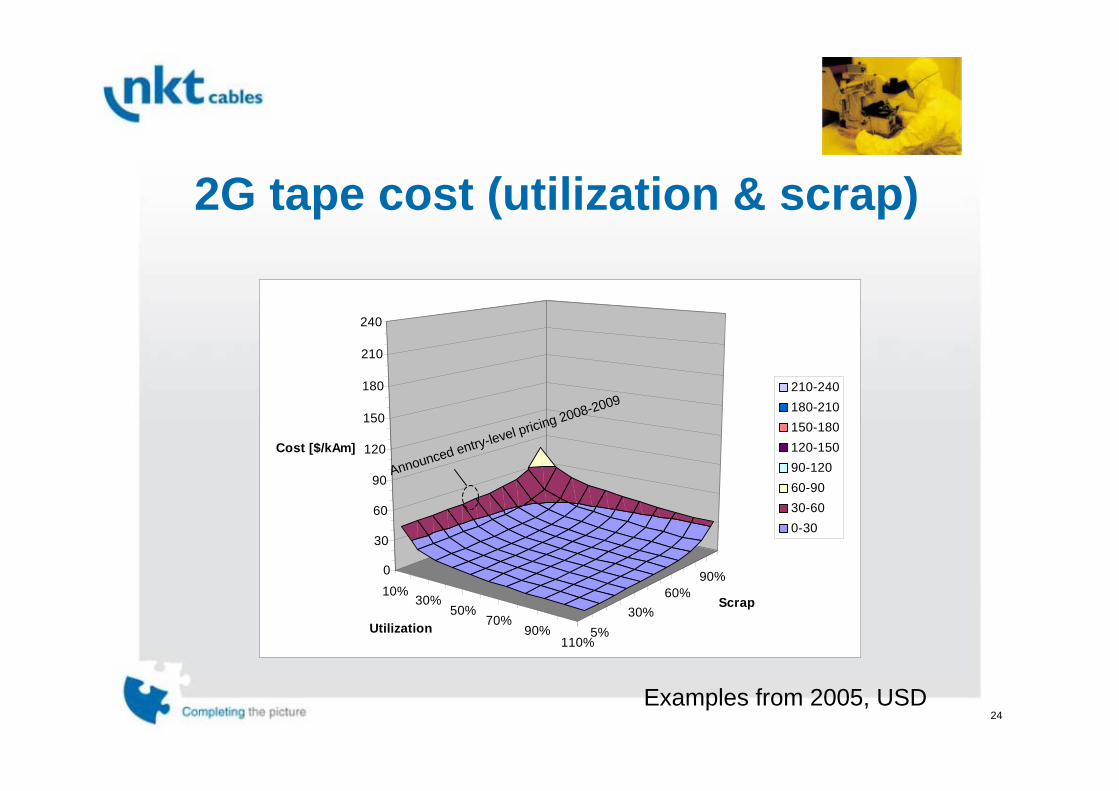
1G tape cost (utilization & scrap)
90%60%
30%5%
10%
30%
50%
70%
90%
110%
0
30
60
90
120
150
180
210
240
Cost [$/kAm]
Scrap
Utilization
210-240180-210150-180120-15090-12060-9030-600-30
Price level spring 2005
Examples from 2005, USD
2008

22
2G cost
Brass (Cu + Zn)
Solder (Sn + Pb)Protection layer (Ag)
Substrate (Ni + 5-10% W)
HTS layer (YBCO)
Examples from 2005, USD

23
2G tape cost
Examples from 2005, USD
• YBCO on 50 µm Ni substrate• 70 µm brass reinforcement• 10 µm Ag protection layer• 0.18 mm x 4.3 mm• HTS fill factor 0.12• Jc=350 000 A/cm2
• Ic=151 A/tape• Je=193 A/mm2
The materials cost at 5% scrap is 2.27 USD/kAm(0.36 USD/m)
Silver62%
HTS26%
Ni8%
Brass2%
Solder2%
24
90%60%
30%5%
10%30%
50%70%
90%110%
0
30
60
90
120
150
180
210
240
Cost [$/kAm]
Scrap
Utilization
210-240180-210150-180120-15090-12060-9030-600-30
2G tape cost (utilization & scrap)
Examples from 2005, USD
Announced entry-level pricing 2008-2009
25
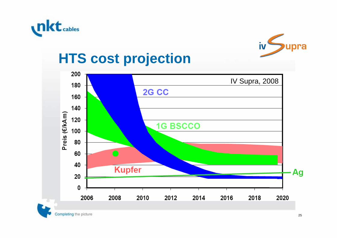
HTS cost projectionIV Supra, 2008
26
Example: The HTS Triax™ Energy Cable
27
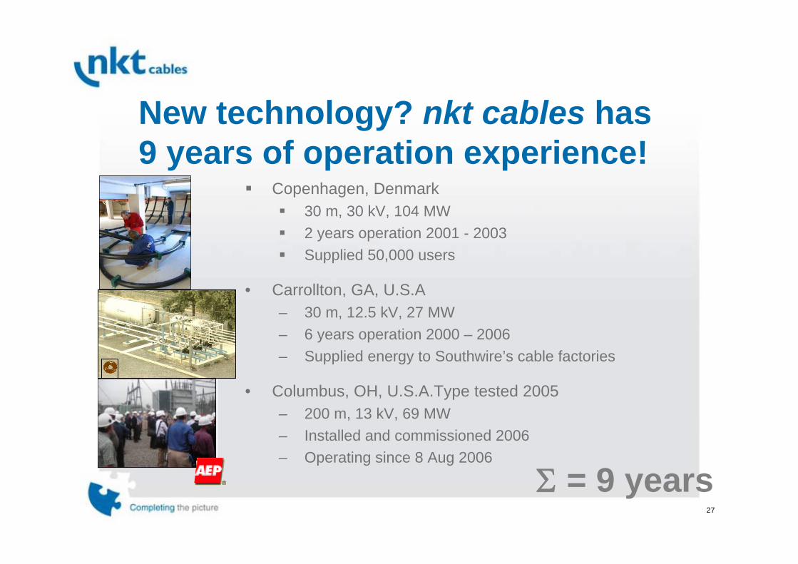
New technology? nkt cables has9 years of operation experience!
Copenhagen, Denmark30 m, 30 kV, 104 MW2 years operation 2001 - 2003Supplied 50,000 users
• Carrollton, GA, U.S.A– 30 m, 12.5 kV, 27 MW– 6 years operation 2000 – 2006– Supplied energy to Southwire’s cable factories
• Columbus, OH, U.S.A.Type tested 2005– 200 m, 13 kV, 69 MW – Installed and commissioned 2006– Operating since 8 Aug 2006
Σ = 9 years
28
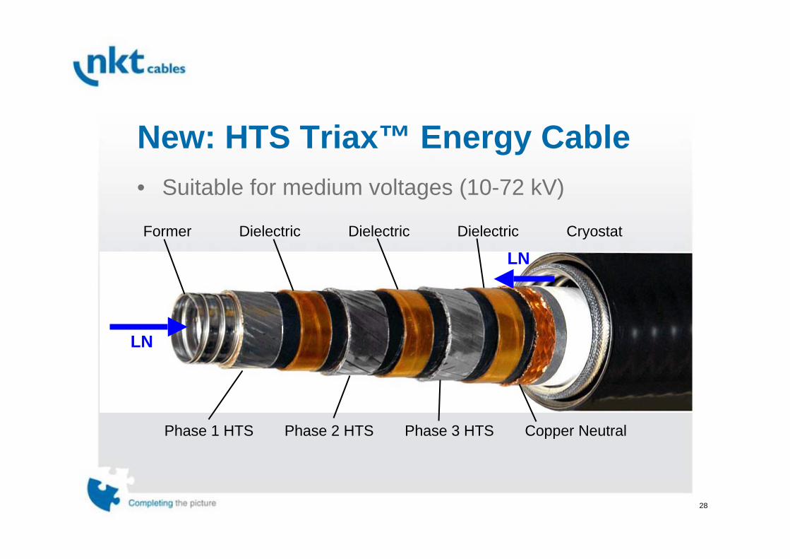
New: HTS Triax™ Energy Cable
CryostatFormer
Phase 2 HTS Phase 3 HTS
Dielectric Dielectric Dielectric
Phase 1 HTS Copper Neutral
LN
LN
• Suitable for medium voltages (10-72 kV)

29
Terminations
• Three-phase terminations• Vertical insulators
Neutral Connection
3 Phase Connections

30
Splice in underground vault
• Cable was cut in two pieces• Three-phase splice

31
Cooling system• Cooling machines have become 1/3 of the size
compared to that of 5 years ago
9 m7 m
4 m

32
Type tested• XLPE standards
– IEC-60840– IEEE 400.2 – ICEA S-94-649-2000
• Fluid-filled standards– IEC-141-1, 141-4– AEIC CS-1-90
• Accessories– IEC-61462– IEEE-48-1996
• Applicable parts (HV testing, load testing, pressure)• Additional tests (Cryogenic)
33
Applications of HTS Energy Cables
34
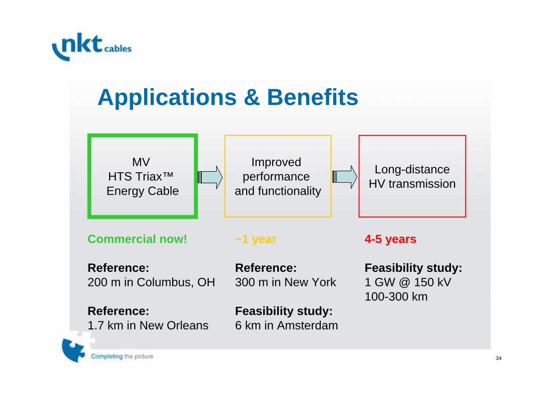
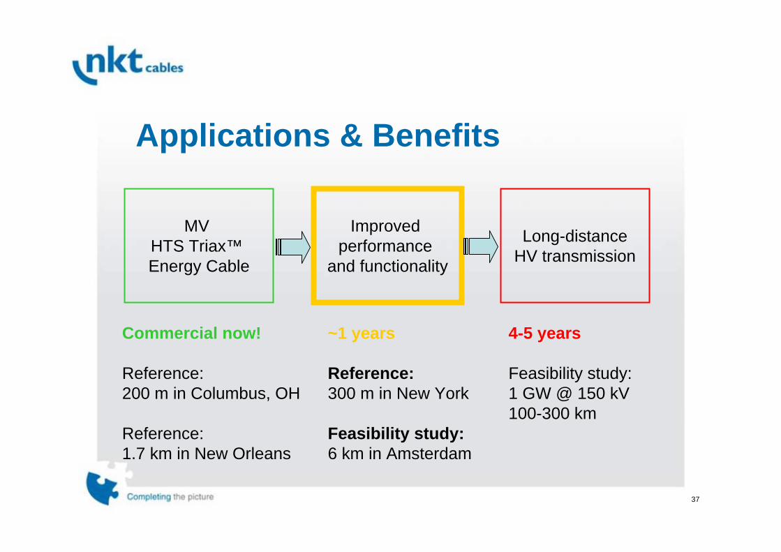
Applications & Benefits
MV HTS Triax™ Energy Cable
Improved performance
and functionality
Long-distanceHV transmission
Commercial now!
Reference:200 m in Columbus, OH
Reference:1.7 km in New Orleans
~1 year
Reference:300 m in New York
Feasibility study:6 km in Amsterdam
4-5 years
Feasibility study:1 GW @ 150 kV100-300 km

35
• Energized: 8 Aug 2006• Date: 8 Aug 2007 • Time since start: 8756 h/365 d• Time in operation: 8752 h/365 d• Cable outings: 1
– Service outings: 0– Scheduled outings: 1– Failures: 0
• Availability: 99.95%• Min Power: 18 MW• Max Power: 58 MW• Ave Power: 30 MW• Transmitted energy: 264 GWh
Reference: 200 m Columbus, OH
36
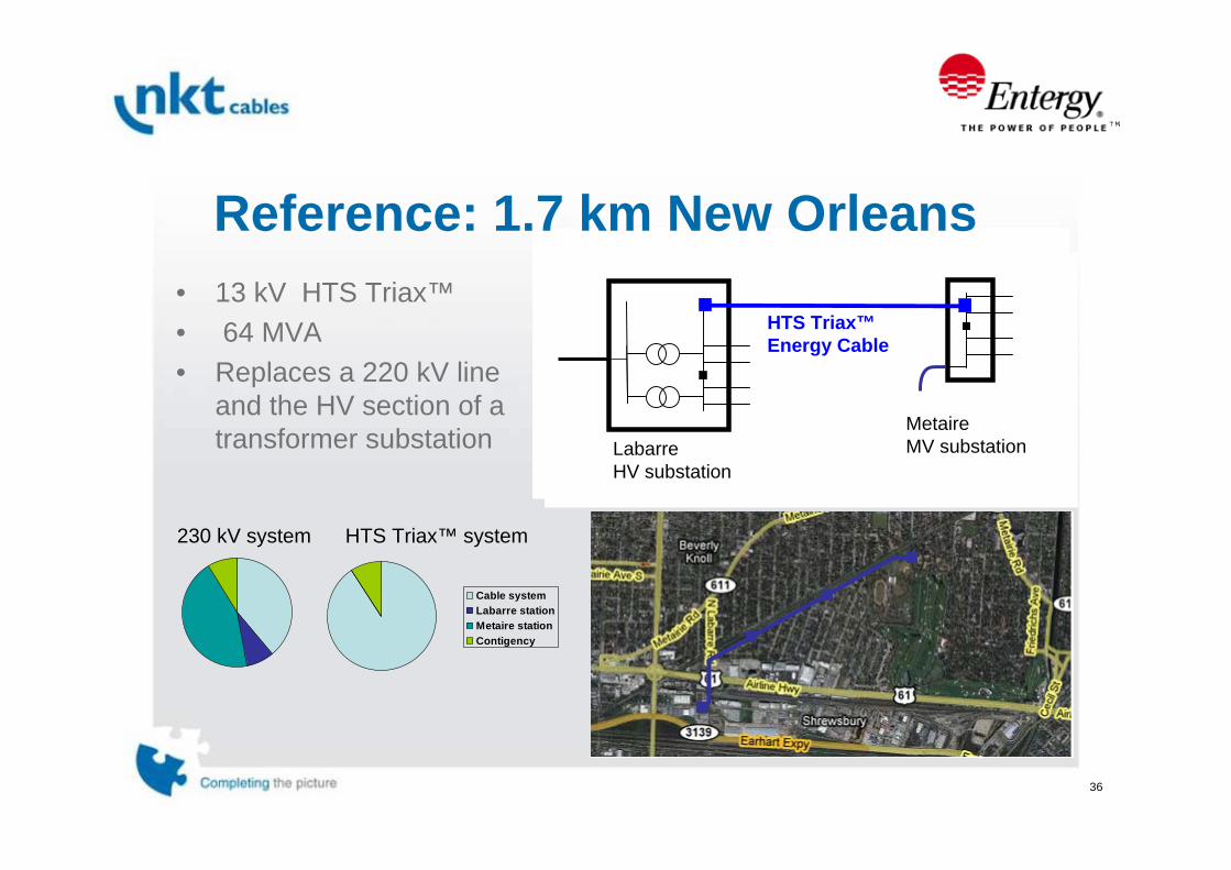
LabarreHV substation
230 kV XLPE
MetaireHV substation
Reference: 1.7 km New Orleans• 13 kV HTS Triax™• 64 MVA• Replaces a 220 kV line
and the HV section of a transformer substation
HTS Triax™Energy Cable
LabarreHV substation
Metaire MV substation
Cable systemLabarre stationMetaire stationContigency
230 kV system HTS Triax™ system
37
Applications & Benefits
MV HTS Triax™ Energy Cable
Improved performance
and functionality
Long-distanceHV transmission
Commercial now!
Reference:200 m in Columbus, OH
Reference:1.7 km in New Orleans
~1 years
Reference:300 m in New York
Feasibility study:6 km in Amsterdam
4-5 years
Feasibility study:1 GW @ 150 kV100-300 km

38
unlimited fault current
Reference: 300 m New York City• New functionality: HTS cables have the
inherent ability to limit fault currents
Zero voltage
Nominalvoltage
Critical current
Current [kA]
Voltage [kV]
limited fault current
nominal current

39
Reference: 300 m New York City
Station-to-station tie on low side of Transformers• Can carry full station load at MV• Share transformer redundancy
between distribution stations• Increase transformer asset
utilization
HV
110-230 kV
HV
110-230 kV
HTS Triax™HTS FCL Cable
Increased reliability and resilience
MV distribution
10-20 kV
MV distribution
10-20 kV

40
Feasibility: 6 km in AmsterdamGas Pressure Cable
HTS Triax™ Energy Cable
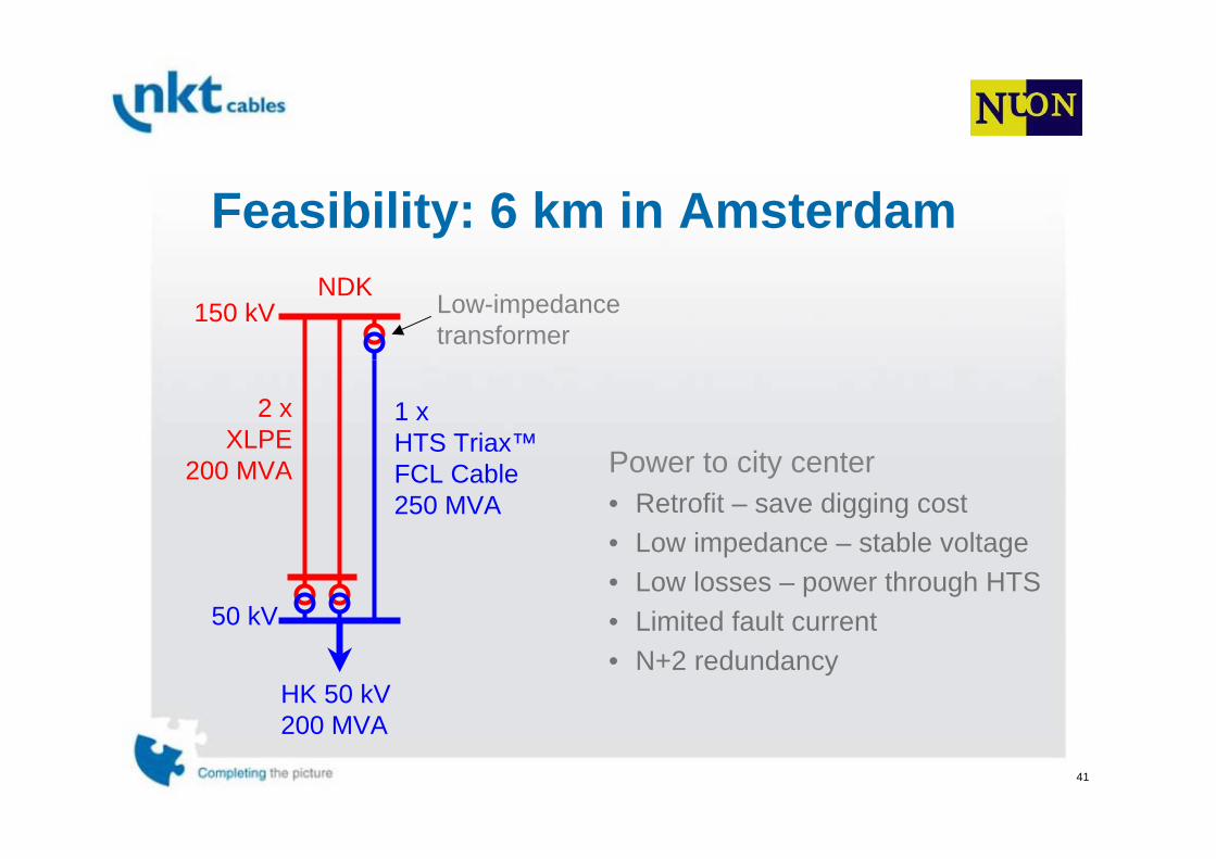
41
Feasibility: 6 km in Amsterdam
Power to city center• Retrofit – save digging cost• Low impedance – stable voltage• Low losses – power through HTS• Limited fault current• N+2 redundancy
Low-impedancetransformer
HK 50 kV200 MVA
NDK
2 xXLPE
200 MVA
1 xHTS Triax™FCL Cable250 MVA
150 kV
50 kV

42
Applications & Benefits
MV HTS Triax™ Energy Cable
Improved performance
and functionality
Long-distanceHV transmission
Commercial now!
Reference:200 m in Columbus, OH
Reference:1.7 km in New Orleans
~1 years
Reference:300 m in New York
Feasibility study:6 km in Amsterdam
4-5 years
Feasibility study:1 GW @ 150 kV100-300 km

43
HTS Coax High-Voltage Cables• Same materials and machinery • Suitable for higher voltages, 50 - 150 kV
Ph1Ph2
Ph3
Dielectric Neutral
44
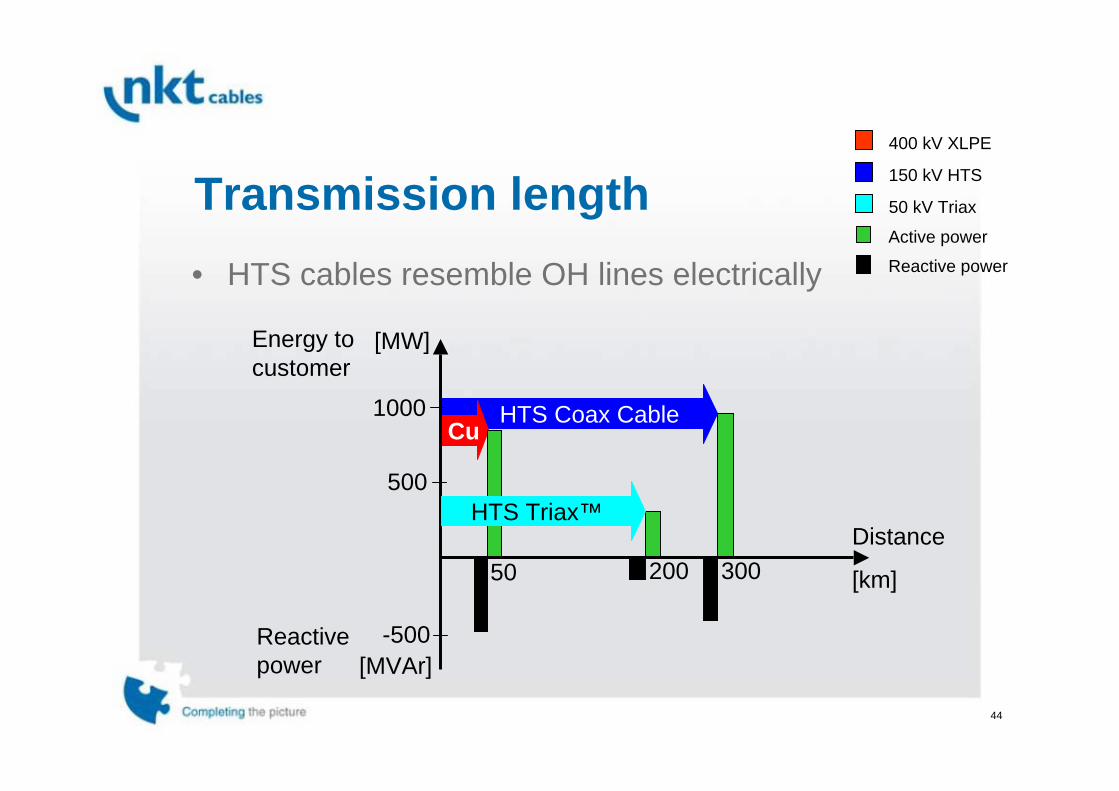
Transmission length
[MW]
[MVAr]
HTS Coax CableCu
-500
500
1000
Energy to customer
Reactivepower
HTS Triax™ Distance
[km]30020050
• HTS cables resemble OH lines electrically
400 kV XLPE
50 kV Triax
Active power
150 kV HTS
Reactive power
45
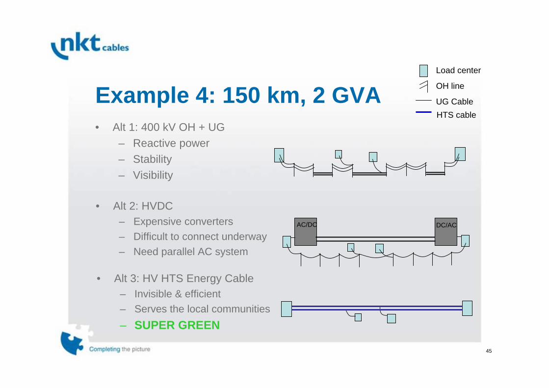
Example 4: 150 km, 2 GVA• Alt 1: 400 kV OH + UG
– Reactive power– Stability– Visibility
AC/DC DC/AC
• Alt 3: HV HTS Energy Cable– Invisible & efficient– Serves the local communities– SUPER GREEN
• Alt 2: HVDC– Expensive converters– Difficult to connect underway– Need parallel AC system
Load center
UG CableHTS cable
OH line
46
Conclusion1. Materials
• Many interesting aspects
2. Cost • comes down with increasing maturity
3. Applications:• First commercial product available• Imroved properties (reduced loss) and functionality (FCL)• Great potential in transmission

47
Thank you!


