
HAL Id: hal-00119196https://hal.archives-ouvertes.fr/hal-00119196
Submitted on 8 Dec 2006
HAL is a multi-disciplinary open accessarchive for the deposit and dissemination of sci-entific research documents, whether they are pub-lished or not. The documents may come fromteaching and research institutions in France orabroad, or from public or private research centers.
L’archive ouverte pluridisciplinaire HAL, estdestinée au dépôt et à la diffusion de documentsscientifiques de niveau recherche, publiés ou non,émanant des établissements d’enseignement et derecherche français ou étrangers, des laboratoirespublics ou privés.
Mapping the IEC 62264 models onto the Zachmanframework for analysing products information
traceability: a case studyHervé Panetto, Salah Baïna, Gérard Morel
To cite this version:Hervé Panetto, Salah Baïna, Gérard Morel. Mapping the IEC 62264 models onto the Zachmanframework for analysing products information traceability: a case study. Journal of Intelligent Man-ufacturing, Springer Verlag (Germany), 2007, 18 (6), pp.679-698. <10.1007/s10845-007-0040-x>.<hal-00119196>
Panetto H., Baïna, S., Morel G. (2007). Mapping the IEC 62264 models onto the Zachman framework for analysing products information traceability: a case study. Journal of Intelligent Manufacturing, Springer Verlag, ISSN 0956-5515, à paraître
-1-
MAPPING THE IEC 62264 MODELS ONTO THE ZACHMAN FRAMEWORK FOR ANALYSING PRODUCTS INFORMATION TRACEABILITY:
A CASE STUDY
Hervé Panetto, Salah Baïna, Gérard Morel
Centre de Recherche en Automatique de Nancy (CRAN - UMR 7039), Nancy-University, CNRS,
F-54506 Vandoeuvre les Nancy, France, [email protected]
Abstract: In order to face new regulation directives regarding the environment and also for improving their customer relationship, enterprises have to increasingly be more able to manage their product information during the entire lifecycle. One of the objectives among others in this paper is to deal with product traceability along the product lifecycle. To meet this objective, the information system has to be designed and, further built in such a way all information regarding products is recorded. The IEC 62264 standards define generic logical models for exchanging product and process information between business and manufacturing levels of enterprise applications. Thus, it can be a base for product information traceability. However, its complexity comes from the fact it mixes conceptual and implementation details while no methodology exists that defines how to instantiate it. Product traceability is then needed to increase its abstraction level in order to concentrate on its concepts and managing its application by providing a methodology for its instantiation. In this paper, we propose to map the IEC 62264 standard models to a particular view of Zachman framework in order to make the framework concrete as a guideline for applying the standard and for providing the key players in information systems design with a methodology to use the standard for traceability purposes. Keywords: Zachman framework, IEC 62264, traceability, products modelling

1 INTRODUCTION
In order to meet the latest worldwide directives imposed for a better environment and a
seamless customer relationship, product traceability is now one of the key industrial issues.
However, in many scenarios, enterprises encounter the challenging task of enabling
coexistence between new and existing systems where product information is dispersed.
Industry solutions today have implemented their software architectures on "building block"
technology platforms each providing their own competitive advantage within their respective
domain. However, with the introduction of these new technology platforms comes the ever-
increasing complexity of extending these platforms to promote high degrees of
interoperability with their respective competitors in order to provide a complete end-to-end
business solution that meets the demands of the customer in getting the most accurate
information about their product life cycle. Especially, at the level of the production systems,
enterprises have to face production data exchange between manufacturing control functions
and other enterprise functions. The goal is to reduce the risk, cost, and errors associated with
implementing data and model interfaces, enabling enterprise systems and control systems that
interoperate and easily integrate.
Standardisation initiatives, either supported by standardisation bodies such as ISO, IEC, or
developed by industrial (ISA) or European projects have already attempted to solve this issue.
However, each of them focuses on one particular aspect of such interoperability without
aligning their enterprise knowledge and skill for taking advantage of a seamless cooperation.
However, these standards are closely related to implementation issues and are complex to
understand and to put in practice. There is a clear need to make them more abstract and to
define methodologies in order to facilitate understanding of their defined concepts.
Many frameworks have been developed in order to concentrate best practices in the
development of systems. One of them, the Zachman framework for Enterprise Architecture,
(Zachman, 1987; Sowa and Zachman, 1992) offers a static overview of all elements involved

Panetto H., Baïna, S., Morel G. (2007). Mapping the IEC 62264 models onto the Zachman framework for analysing products information traceability: a case study. Journal of Intelligent Manufacturing, Springer Verlag, ISSN 0956-5515, à paraître
-3-
in information systems. However, it is so general and without any concrete guidelines that it
is difficult to make it concrete in the development of enterprise applications.
In order to facilitate the instantiation of the IEC 62264 standard models for product
information traceability, the objective of this paper is to define abstract views of the models
and to propose a methodology based on mapping the IEC 62264 standard models, through a
systematic approach, onto the Zachman framework in order to clarify the use of the
framework in the context of the product information traceability.
Much effort has been attempted to map different enterprise architecture frameworks and
languages onto the Zachman Framework: Sowell (1999) has proposed a mapping of the the
views and individual products of the C4ISR Architecture Framework (C4ISR, 1997) to the
cells of the Zachman Framework which provides templates and guidelines for modelling the
enterprise features with a C4ISR perspective; O'Rourke (2003), in his book, has explained the
different Zachman player’s views through case studies; Frankel, et al. (2003) have mapped
the MDA (Model Driven Architecture) (Mellor, et al., 2004) models used in software
development, the UML (Unified Modeling Language) diagrams (UML, 2005) and the many
standards related to MDA onto the framework cells in order to facilitate applying the MDA
approach for software development; Osvalds (2003) has also proposed some mapping of
UML diagrams onto the Zachman framework to provide a traceable methodology for
developing architectural models of the enterprise; Noran (2003) has proposed an analysis of
the Zachman framework and its mapping onto the Generalised Enterprise Reference
Architecture and Methodology (GERAM) framework (ISO IS 15704, 2000) requirements to
compare the ability of the Zachman framework to cover the complete scope of the GERAM
metamodel, such as life cycle/life history concepts, modelling framework. In some extent,
delaHostria (2005) has contributed to this field. He studied how the IEC 62264 may be
related to enterprise architecture frameworks by combining it with the ISO 15745 standard
(ISO 15745, 2003). All these proposals try to compare themselves to the Zachman framework
while the proposed work aims to be complementary by defining detailed perspectives of each
framework players’view through the IEC 62264 models. Our work is a contribution to the
Model Driven Engineering (MDE) (Bezivin, 2004) domain, focused on manufacturing
enterprises, which refers to the systematic use of models as primary engineering artefacts
throughout the engineering lifecycle. This domain is being considered as an important
departure from traditional techniques in such areas as software engineering, system
engineering and data engineering.
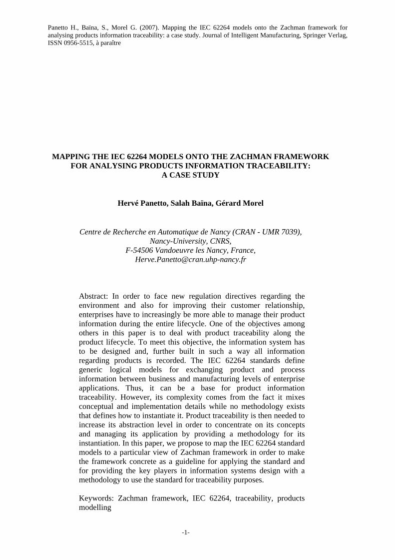
In order to deal with product traceability information through Product Lifecycle Management
(PLM) and related to the various enterprise applications, we consider a product-centric
paradigm, as shown in Figure 1 (Baïna, et al, 2005), where the enterprise is composed of two
separated worlds: (i) on one hand, a world in which the product is mainly seen as a physical
object, this world is called the manufacturing world and it handles systems with
manufacturing execution that is tightly related to the shop-floor level, (ii) on the other hand, a
world where the product is seen as a service released in the market. This world is called the
business world and relates on model-driven product/process engineering. The main issue in
product traveability is then to take into account information synchronisation between these
two worlds during the system modelling phase.
ERP
APS
CRMERP
APS
CRM
Business world
MESMES
SCESCE
MESMES
SCESCE
Product
Manufacturing world
PLM
Model-DrivenProduct/ProcessEngineering
ManufacturingExecution
Product LifecycleManagement
Figure 1: Product-centric paradigm (adapted from (Baïna, et al., 2005)

Panetto H., Baïna, S., Morel G. (2007). Mapping the IEC 62264 models onto the Zachman framework for analysing products information traceability: a case study. Journal of Intelligent Manufacturing, Springer Verlag, ISSN 0956-5515, à paraître
-5-
After presenting, in the next section, the traceability issues in an industrial context, we will
give to the reader a brief overview of the IEC 62264 models (section 3) and the Zachman
Framework (section 0). Then, we will discuss, in section 5 our mapping of the IEC 62264
models onto the Zachman framework which result in a methodology for instantiating the
models based on a generic workflow defining. We will then apply, in section 6, the
methodology on an industrial case study and will show the first promising results. Finally, the
last section will conclude and will propose further research in this context.
2 PRODUCT TRACEABILITY The term “traceability” related to the product has been defined since the 90’s (Cheng and
Simmons, 1994), when a series of industrial needs had been highlighted into the
establishment of ISO 9000 procedures. Generally, product traceability is the ability of a user
(manufacturer, supplier, vendor…) to trace a product through its processing procedures, in a
forward and/or backward direction (Jansen-Vullers, et al., 2003). Physically, the product
traceability deals with maintaining records of all materials and parts along a defined lifecycle
(e.g. from raw material purchasing to finished goods selling) using a coding identification
system.
Traceability systems are adopted, according to laws, in the food sector, in manufacturing, in
the pharmaceutical sector, in distribution, and in construction. Traceability systems can be
useful to increase the quality and safety of the product, for brand protection, and can increase
efficiency in production and distribution. Traceability has a different meaning in literature:
internal traceability, that is the traceability inside the factory and the production system and
external traceability that follows the product into its relations with customers, maintenance,
suppliers, etc. (Cheng and Simmons, 1994). Another meaning is between Backward and
Forward Traceability (Jansen-Vullers, et al., 2003). Backward Traceability records
information and data on the past history of the product. Forward traceability explains what
will happen to a certain product, all the processes and output that the product in question
went into (Terzi, 2005 ; Terzi, et al., 2005). This information is written before production
begins and aims to give all the information that are needed to the production. This kind of
traceability could be very useful in automated manufacturers (McFarlane, et al., 2005).
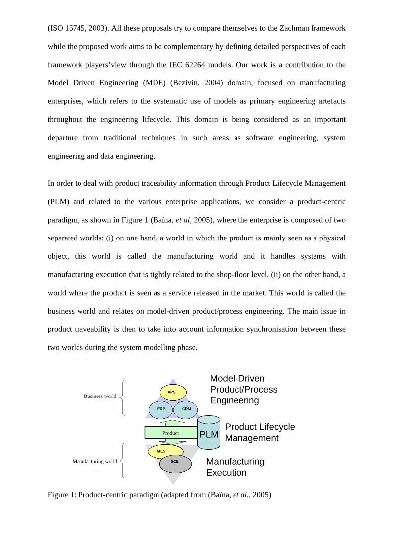
The next section will briefly present the IEC 62264 and the abstraction of its models using
UML class diagram notations in order to better understand its perspective for product
information traceability. Then we will present a brief overview of the Zachman framework
before discussing the proposed mapping.
3 IEC 62264 STANDARD FOR ENTERPRISE-CONTROL SYSTEMS INTEGRATION In this section the IEC 62264 (IEC 62264, 2002) standard is presented. This paper will focus,
mainly in the first part named “Models and Terminology” which specifies to a set of
reference models for information exchange to facilitate the integration of business
applications and manufacturing control applications, within an enterprise. The full standard is
composed by six different parts designed for defining the interfaces between enterprise
activities and control activities. Among all its parts, part 1 describes the relevant functions
within an enterprise and within the control domain of an enterprise, stating which objects are
normally exchanged between these domains.
Figure 2 depicts the different levels of a functional hierarchy model: business planning and
logistics, manufacturing operations and control, and batch, continuous, or discrete control.
The model shows the hierarchical levels at which decisions are made. The interface addressed
in the standard is between Level 4 and Level 3 of the hierarchy model. This is generally the
interface between plant production scheduling and operation management and the various
manufacturing operations and control also known as plant floor coordination.

Panetto H., Baïna, S., Morel G. (2007). Mapping the IEC 62264 models onto the Zachman framework for analysing products information traceability: a case study. Journal of Intelligent Manufacturing, Springer Verlag, ISSN 0956-5515, à paraître
-7-
Business Planning & LogisticsPlant Production Scheduling,Operational Management, etc
Manufacturing Operations & Control
Dispatching Production, Detailed ProductionScheduling, Reliability Assurance,etc ...
BatchControl
DiscreteControl
ContinuousControl
Level 4 - Business logistics
Level 3 - Manufacturingoperations
Level 2 - Control systems
Level 1 - Sensors & actuators
Level 0 - The process
Figure 2: Functional hierarchy as defined in IEC 62264
Levels 2, 1, and 0 present the cell or line supervision functions, operations functions, and
process control functions, not addressed by this standard. Level 0 indicates the process,
usually the manufacturing or production process. Level 1 indicates manual sensing, sensors,
and actuators used to monitor and manipulate the process. Level 2 indicates the control
activities, either manual or automated, that keeps the process stable or under control. There
are several different models for the functions at these levels based on the actual production
strategy used.
The key aspects for integrating the business applications at Level 4 and the manufacturing
operations and control applications at Level 2 (and below) are the information structures and
exchanges managed by Level 3 activities, applications, processes, resources, and functions.
Examples of Level 3 activities include the management of various manufacturing operations,
such as, production, maintenance, product quality testing, and material handling. Enterprise
applications dealing with these exchanges are, at the business levels, ERP (Enterprise
Resource Planning) systems, APS (Advanced Planning and Scheduling) systems, CRM
(Customer Relationship Management) systems and, at the manufacturing level, MES
(Manufacturing Execution Systems), SCE (Supply Chain Execution) systems. In particular,

MES functions relate production monitoring, rescheduling and control including production
requests and responses, materials (raw and finished) and resources (equipment and personnel)
traceability information.
To take into account the various exchanged information, through the product representation,
the standard defines a set of eight models that specifies all concepts for enterprise-control
integration. Each model concerns a particular view of the integration problem (IEC 62264,
2002).
The different models from IEC 62264 are linked together in a logical way in order to define a
hierarchy of models (Figure 3). The production information presents what was made and
what was used. Its elements correspond to information in production scheduling that listed
what to make and what to use. The production scheduling elements correspond to information
in the product definition that shows what is specified to make a product. The product
definition elements correspond to information in the process segment descriptions that
present what can be done with the production resources. This hierarchy will be the base of
our model mapping onto the Zachman framework as proposed in section 5.
ProductionCapability
CapabilityProperty
ResourceCapability
ProductionCapability
What resourcesare available
ProductionPerformance
ProductionResponse
SegmentResponse
ActualProperty
ResourceActual
ProductionInformation
What wasmade & used
ProductionRequest
SegmentRequirement
RequirementProperty
ResourceRequirement
ProductionSchedulingWhat is it to bemade & used
ProductionSchedule
ProductionRule
ProductSegment
SpecificationProperty
ResourceSpecification
ProductDefinition
What must be definedto make a product
ProcessSegment
SegmentProperty
ResourceSegmentCapability
ProcessSpecificationWhat can be donewith the resources
Figure 3: The IEC 62264 models hierarchy (IEC 62264, 2002)

Panetto H., Baïna, S., Morel G. (2007). Mapping the IEC 62264 models onto the Zachman framework for analysing products information traceability: a case study. Journal of Intelligent Manufacturing, Springer Verlag, ISSN 0956-5515, à paraître
-9-
In order to develop the abstraction meaning of the concepts, based on the standard (which is
more at a logical level), we have de-normalised and conceptualised its models and then
represented them using the UML class diagram notation (only two of them out of the eight
available have been reproduced because of the limitation of space):
• Product Definition Model (Figure 5)
The product definition model is information shared between production rules, bill of
material, and bill of resources. A product definition contains a listing of the exchanged
information about a product. The information is used in a set of product segments that
are the values needed to quantify a segment for a specific product. A product segment
identifies, references, or corresponds to a process segment. It is related to a specific
product, while a process segment is product independent. The collection of product
segments for a product gives the sequence and ordering of segments required to
manufacture a product in sufficient detail for production planning and scheduling. The
corresponding production rule presents the additional detail required for actual
production.
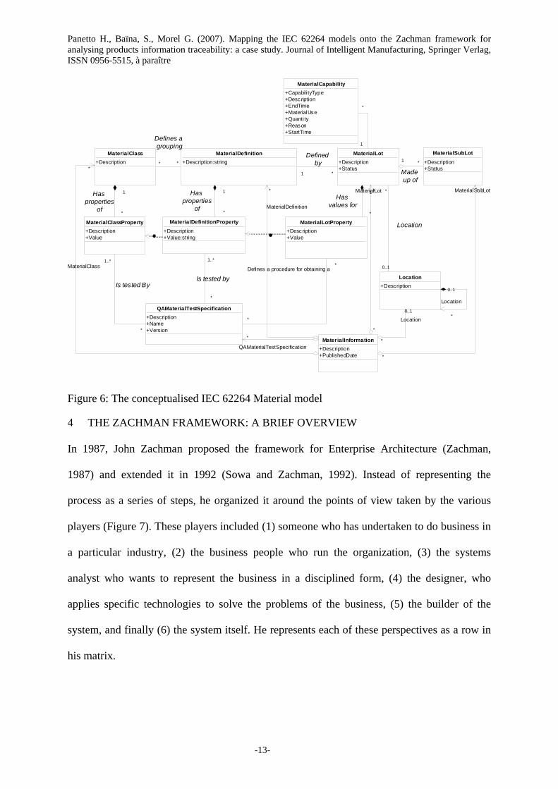
• Material Model (Figure 6)
The Material model defines the actual materials, material definitions, and information
about classes of material definitions. Material information includes the inventory of
raw, finished, and intermediate materials. Material classes are defined to organise
materials. A Material definition is a means to describe goods with similar
characteristics for purposes of scheduling and planning.
• Equipment Model
The equipment model contains the information about specific equipment, the classes of
equipment, equipment capability tests, and maintenance information associated with
equipment.
• Personnel Model

The personnel model contains the information about specific personnel, classes of
personnel, and qualifications of personnel.
• Process Segment Model
The process segment model contains process segments that list the classes of personnel,
equipment, and material needed, and/or it may present specific resources, such as
specific equipment needed. A process segment may list the quantity of the resource
needed. A process segment is related to a product segment that can occur during
production, as presented in the product definition model.
• Production Schedule Model
A request for production shall be listed as a production schedule. A production schedule
shall be made up of one or more production requests. A request for production for a
single product identified by a production rule shall be shown as a production request. A
production request contains the information required by manufacturing to fulfil
scheduled production. This may be a subset of the business production order
information, or it may contain additional information not normally used by the business
system. A production request may identify or reference the associated production rule.
A production request shall contain at least one segment requirement, even if it spans all
production of the product.
• Production Capability Model
The production capability information is the collection of information about all
resources for production for selected times. This is made up of information about
equipment, material, personnel, and process segments. It describes the names, terms,
statuses, and quantities of which the manufacturing control system has knowledge. The
production capability information contains the vocabulary for capacity scheduling and
maintenance information.
• Production Performance Model
The performance of the requested manufacturing requests shall be listed as production
performance. Production performance shall be a collection of production responses. The
Panetto H., Baïna, S., Morel G. (2007). Mapping the IEC 62264 models onto the Zachman framework for analysing products information traceability: a case study. Journal of Intelligent Manufacturing, Springer Verlag, ISSN 0956-5515, à paraître
-11-
responses from manufacturing that are associated with a production request shall be
used as production responses. There may be one or more production responses for a
single production request if the production facility needs to split the production request
into smaller elements of work. A production result may include the status of the request,
such as the percentage complete, a finished status, or an aborted status.
In order to facilitate understanding of the UML class diagrams, the Figure 4 summarises the
formalism (UML, 2005).
Figure 4: The UML class diagram formalism

ProductSegmentType+Description+Duration+Parameter
ProcessSegmentType+Description+Duration+Parameter+Publ ishedDate
1..*
*
Corresponds to*
May be made
up
**
Has an execution
dependency on
ManufacturingBillType+Description+Quantity
PersonnelSpecificationType+Description+Quanti ty
EquipmentSpecificationType+Description+Quantity:Quantity
MaterialSpecificationType+Description+MaterialUse+Quantity:Integer
MaterialSpecificationPropertyType+Description+Quanti ty+Value
PersonnelSpecificationPropertyType+Description+Quanti ty+Value
EquipmentSpecificationPropertyType
+Description+Quantity+Value
*
0..1
Is defined as a collection
of
*
0..1
Is defined as a collection
of
*
0..1
*
0..1
*
May be made up of
1..*
1
relates
*
0..1
Is defined as a collection of
ProductInformationType+Description+PublishedDate
*
ProductDefinitionType+Description+PublishedDate+Version
0..1*
ProductDefinition
1..*
ProductSegment
0..1
Has associated
0..1
*
Location+Description
* Location
0..1
0..1
0..1
Location
0..1
0..1Location0..1
0..1
Location
ProductProductionRuleType+DurationUnit of Measure+PublishedDate+Description+Version
Material Model
*
Has associated
ProductParameter+Description+Name+Value
0..1
*
Is defined as a collection of
ProductSegmentCapability+Capabili tyType+Description+EndTime+Reason+StartTime
1*
corresponds to
1..*
1
*1relates
ProductSegmentDependency+OtherValue:string
Personnel Model
Equipment Model
EquipmentClass+Description
0..1
EquipmentClass
*
Equipment+Description
0..1
Equipment
*
}{ XOR
MaterialClass+Description
MaterialDefinition+Description:string
0..1 MaterialDefinition
*
0..1MaterialClass
*
}{ XOR
PersonnelClassType+Description
PersonType+Description+PersonName
**
Defined By
0..1
PersonnelClass
*
0..1
Person
*
}{ XOR
Figure 5: The conceptualised IEC 62264 Product Definition model
Panetto H., Baïna, S., Morel G. (2007). Mapping the IEC 62264 models onto the Zachman framework for analysing products information traceability: a case study. Journal of Intelligent Manufacturing, Springer Verlag, ISSN 0956-5515, à paraître
-13-
MaterialClass+Description
MaterialDefinition+Description:string
QAMaterialTestSpecification+Description+Name+Version
MaterialLot+Description+Status
MaterialSubLot+Description+Status
MaterialClassProperty+Description+Value
MaterialDefinitionProperty+Description+Value:string
MaterialLotProperty+Description+Value
*
1..*
Is tested By
*
1..*
Is tested by
*Defines a procedure for obtaining a
*
*1
Defined by *1
Made up of
*
1Has properties
of *
1Has properties
of*
1Has
values for
* *
Defines a grouping
Location+Description
*
Location
0..1
MaterialCapability+Capabili tyType+Description+EndTime+MaterialUse+Quantity+Reason+StartTime
*
1
MaterialInformation+Description+PublishedDate
0..1
Location
*
*
MaterialDefinition
*
MaterialClass
*MaterialLot
*
*
QAMaterialTestSpecification
*MaterialSubLot
*
0..1
*
Location
Figure 6: The conceptualised IEC 62264 Material model
4 THE ZACHMAN FRAMEWORK: A BRIEF OVERVIEW
In 1987, John Zachman proposed the framework for Enterprise Architecture (Zachman,
1987) and extended it in 1992 (Sowa and Zachman, 1992). Instead of representing the
process as a series of steps, he organized it around the points of view taken by the various
players (Figure 7). These players included (1) someone who has undertaken to do business in
a particular industry, (2) the business people who run the organization, (3) the systems
analyst who wants to represent the business in a disciplined form, (4) the designer, who
applies specific technologies to solve the problems of the business, (5) the builder of the
system, and finally (6) the system itself. He represents each of these perspectives as a row in
his matrix.

Figure 7: The Zachman framework matrix
He then acknowledged that each of these participants is looking at the same categories of
information. If the roles are represented by rows in a matrix, the things examined can be
represented by columns. Specifically, the columns represent the data manipulated by an
organization (what), its functions and processes (how), locations where business is conducted
(where), events that trigger business activities (when), the people and organizations involved
(who), and the motivations and constraints which determine how the business behaves (why).
The set of cells thus defined turn out to house all the various modelling techniques we use in
the information processing industry. Moreover, they identify some places where we could use
some new models. In addition, the translations required to go from row to row reveal
interesting things about both how we do and how we should do our business. The Zachman
framework however is not sufficient as a practical framework for enterprise architecture. The
Zachman framework offers a static overview of all elements involved in information systems.
It does not define the processes to go from an existing (as-is) situation to a future (to-be) state
and neither does it define an organisation to support such processes.
Based on work by John A. Zachman
VA Enterprise Architecture
DATAWhat
FUNCTIONHow
NETWORKWhere
PEOPLEWho
TIMEWhen
MOTIVATIONWhy
DATAWhat
FUNCTIONHow
NETWORKWhere
PEOPLEWho
TIMEWhen
MOTIVATIONWhy
SCOPE(What is importantfor the enterprise)
Planner
ENTERPRISEMODEL(What is available)
Owner
SYSTEM MODEL(How to build products)
Designer
TECHNOLOGYMODEL(How to implement)
Builder
DETAILEDREPRESENTATIONS
Sub-Contractor
FUNCTIONINGENTERPRISE
SCOPE(What is importantfor the enterprise)
Planner
ENTERPRISEMODEL
(What is available)
Owner
SYSTEM MODEL(How to build products)
Designer
TECHNOLOGYMODEL
(How to implement)
Builder
DETAILEDREPRESENTATIONS
Sub-Contractor
FUNCTIONINGENTERPRISE
Things Important to the Business
Entity = Class of Business Thing
ProcessesPerformed
Function = Class of Business Process
Semantic Model
Ent = Business EntityRel = Business Relationship
Business ProcessModel
Proc = Business ProcessI/O = Business Resources
Business LogisticsSystem
Node = Business Location Link = Business Linkage
Work Flow Model
People = Organization Unit Work = Work Product
Master Schedule
Time = Business Event Cycle = Business Cycle
Business Plan
End = Business Objective Means = Business Strategy
ImportantOrganizations
People = Major Organizations
Business locations
Node = Major Business Locations
Events Significantto the Business
Time = MajorBusiness Event
Business Goalsand Strategy
Ends/Means =Major Business Goals
Logical DataModel
Ent = Data EntityRel = Data Relationship
Application Architecture
Proc = Application FunctionI/O = User Views
Distributed SystemArchitecture
Node = IS FunctionLink = Line Characteristics
Human InterfaceArchitecture
People = RoleWork = Deliverable
ProcessingStructure
Time = System Event Cycle = Processing Cycle
Business RuleModel
End = Structural Assertion Means = Action Assertion
Physical DataModel
Ent = Segment/Table Rel = Pointer/Key
SystemDesign
Proc = Computer FunctionI/O = Data Elements/Sets
TechnologyArchitecture
Node = Hardware/Software Link = Line Specifications
PresentationArchitecture
People = User Work = Screen Format
ControlStructure
Time = ExecuteCycle = Component Cycle
RuleDesign
End = Condition Means = Action
DataDefinition
Ent = Field Rel = Address
Program
Proc = Language StatementI/O = Control Block
NetworkArchitecture
Node = AddressesLink = Protocols
SecurityArchitecture
People = IdentityWork = Job
Timing Definition
Time = InterruptCycle = Machine Cycle
RuleDesign
End = Sub -Condition Means = Step
Data
Ent = Rel =
Function
Proc =I/O =
Network
Node = Link =
Organization
People = Work =
Schedule
Time = Cycle =
Strategy
End = Means =
Based on work by John A. Zachman
VA Enterprise Architecture
DATAWhat
FUNCTIONHow
NETWORKWhere
PEOPLEWho
TIMEWhen
MOTIVATIONWhy
DATAWhat
FUNCTIONHow
NETWORKWhere
PEOPLEWho
TIMEWhen
Based on work by John A. Zachman
VA Enterprise Architecture
DATAWhat
FUNCTIONHow
NETWORKWhere
PEOPLEWho
TIMEWhen
MOTIVATIONWhy
DATAWhat
FUNCTIONHow
NETWORKWhere
PEOPLEWho
TIMEWhen
MOTIVATIONWhy
- -
Things Important to the Business
Entity = Class of Business Thing
ProcessesPerformed
Function = Class of Business Process
Semantic Model
Ent = Business EntityRel = Business Relationship
Business ProcessModel
Proc = Business ProcessI/O = Business Resources
Business LogisticsSystem
Node = Business Location Link = Business Linkage
Work Flow Model
People = Organization Unit Work = Work Product
Master Schedule
Time = Business Event Cycle = Business Cycle
Business Plan
End = Business Objective Means = Business Strategy
ImportantOrganizations
People = Major Organizations
Business locations
Node = Major Business Locations
Events Significantto the Business
Time = MajorBusiness Event
Business Goalsand Strategy
Ends/Means =Major Business Goals
Logical DataModel
Ent = Data EntityRel = Data Relationship
Application Architecture
Proc = Application FunctionI/O = User Views
Distributed SystemArchitecture
Node = IS FunctionLink = Line Characteristics
Human InterfaceArchitecture
People = RoleWork = Deliverable
ProcessingStructure
Time = System Event Cycle = Processing Cycle
Business RuleModel
End = Structural Assertion Means = Action Assertion
Physical DataModel
Ent = Segment/Table Rel = Pointer/Key
SystemDesign
Proc = Computer FunctionI/O = Data Elements/Sets
TechnologyArchitecture
Node = Hardware/Software Link = Line Specifications
PresentationArchitecture
People = User Work = Screen Format
ControlStructure
Time = ExecuteCycle = Component Cycle
RuleDesign
End = Condition Means = Action
DataDefinition
Ent = Field Rel = Address
Program
Proc = Language StatementI/O = Control Block
NetworkArchitecture
Node = AddressesLink = Protocols
SecurityArchitecture
People = IdentityWork = Job
Timing Definition
Time = InterruptCycle = Machine Cycle
RuleDesign
End = Sub -Condition Means = Step
Data
Ent = Rel =
Function
Proc =I/O =
Network
Node = Link =
Organization
People = Work =
Schedule
Time = Cycle =
Strategy
End = Means =
People = IdentityWork = Job
Timing Definition
Time = InterruptCycle = Machine Cycle
RuleDesign
End = Sub -Condition Means = Step
Data
Ent = Rel =
Function
Proc =I/O =
Network
Node = Link =
Organization
People = Work =
Schedule
Time = Cycle =
Strategy
End = Means =

Panetto H., Baïna, S., Morel G. (2007). Mapping the IEC 62264 models onto the Zachman framework for analysing products information traceability: a case study. Journal of Intelligent Manufacturing, Springer Verlag, ISSN 0956-5515, à paraître
-15-
The framework does identify the exhaustive list of possible documentation standards but does
not define their content or gives examples. Therefore one could conclude that the Zachman
Framework for Enterprise Architecture serves as a checklist ensuring that all aspects involved
in information systems have been taken into account. As a reference frame it is not sufficient
as it needs to be complemented by the process and organisational aspects in addition to
examples of the actual documentation standards. What does it mean to view the development
process in these terms? The major contribution of the framework is its explicit recognition
that there is more at work here than functions and data.
From the beginning, we should be recognizing the organizational issues; from the beginning,
we should be dealing with multiple locations; from the beginning we should be explicitly
concerned with timing – triggers, schedules, and so forth. We do not have models, or even
well developed methods for dealing with many of the cells. Zachman does not advocate the
use of any particular modelling style for those cells where multiple techniques are available,
and he is the first to recognize that in some cells no good techniques exist. It is difficult, for
example, to model the logic (row three) of a distributed information network – at least in a
way that links to our models for functions and data. This represents an assignment for us all.
He has pointed out things that we should be capturing and accounting for in our systems. It is
for us to figure out how to do so.
More details on the Zachman framework may be found on the ZIFA web site
(http://www.zifa.com).
5 MAPPING THE IEC 62264 MODELS ONTO THE ZACHMAN FRAMEWORK FOR PRODUCTS INFORMATION TRACEABILITY
This work proposes to make concrete the use of the Zachman framework as a guideline for
instantiating the conceptual IEC 62264 models and hence, defining the whole set of
information related to the products during their life cycle. This work is complementary to the
MDA™ approach (Model Driven Architecture) (Mellor, et al., 2004) proposed by OMG
which allows separation of platform dependent from platform independent aspects in systems
applications construction and maintenance.
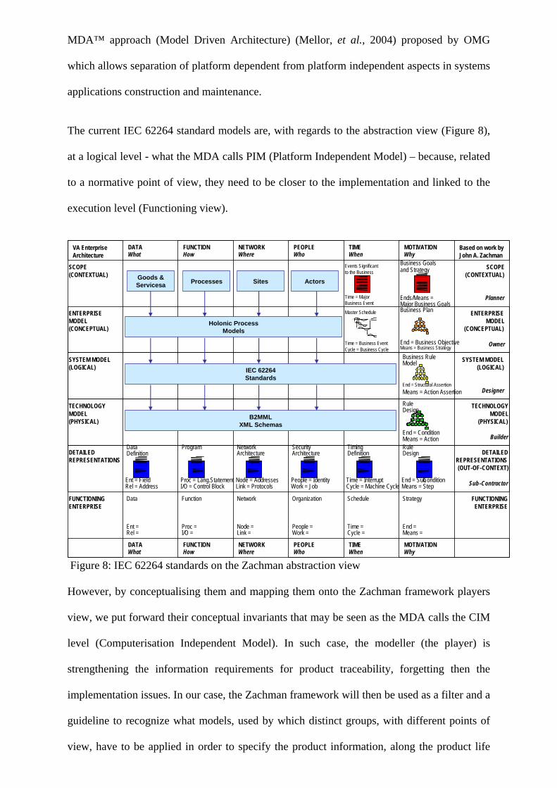
The current IEC 62264 standard models are, with regards to the abstraction view (Figure 8),
at a logical level - what the MDA calls PIM (Platform Independent Model) – because, related
to a normative point of view, they need to be closer to the implementation and linked to the
execution level (Functioning view).
Figure 8: IEC 62264 standards on the Zachman abstraction view
However, by conceptualising them and mapping them onto the Zachman framework players
view, we put forward their conceptual invariants that may be seen as the MDA calls the CIM
level (Computerisation Independent Model). In such case, the modeller (the player) is
strengthening the information requirements for product traceability, forgetting then the
implementation issues. In our case, the Zachman framework will then be used as a filter and a
guideline to recognize what models, used by which distinct groups, with different points of
view, have to be applied in order to specify the product information, along the product life
Based on work by John A. Zachman
VA Enterprise Architecture
DATAWhat
FUNCTIONHow
NETWORKWhere
PEOPLEWho
TIMEWhen
MOTIVATIONWhy
DATAWhat
FUNCTIONHow
NETWORKWhere
PEOPLEWho
TIMEWhen
MOTIVATIONWhy
SCOPE(CONTEXTUAL)
ENTERPRISEMODEL(CONCEPTUAL)
SYSTEM MODEL(LOGICAL)
TECHNOLOGYMODEL(PHYSICAL)
DETAILEDREPRESENTATIONS
FUNCTIONINGENTERPRISE
SCOPE(CONTEXTUAL)
Planner
ENTERPRISEMODEL
(CONCEPTUAL)
Owner
SYSTEM MODEL(LOGICAL)
Designer
TECHNOLOGYMODEL
(PHYSICAL)
Builder
DETAILEDREPRESENTATIONS(OUT-OF-CONTEXT)
Sub-Contractor
FUNCTIONINGENTERPRISE
Master Schedule
Time = Business Event Cycle = Business Cycle
Business Plan
End = Business Objective Means = Business Strategy
Events Significantto the Business
Time = MajorBusiness Event
Business Goalsand Strategy
Ends/Means =Major Business Goals
Business RuleModel
End = Structural Assertion Means = Action Assertion
RuleDesign
End = Condition Means = Action
DataDefinition
Ent = Field Rel = Address
Program
Proc = Lang.StatementI/O = Control Block
NetworkArchitecture
Node = AddressesLink = Protocols
SecurityArchitecture
People = IdentityWork = Job
Timing Definition
Time = InterruptCycle = Machine Cycle
RuleDesign
End = Sub-Condition Means = Step
Data
Ent = Rel =
Function
Proc =I/O =
Network
Node = Link =
Organization
People = Work =
Schedule
Time = Cycle =
Strategy
End = Means =
IEC 62264Standards
Holonic ProcessModels
B2MMLXML Schemas
Goods &Servicesa Processes Sites Actors

Panetto H., Baïna, S., Morel G. (2007). Mapping the IEC 62264 models onto the Zachman framework for analysing products information traceability: a case study. Journal of Intelligent Manufacturing, Springer Verlag, ISSN 0956-5515, à paraître
-17-
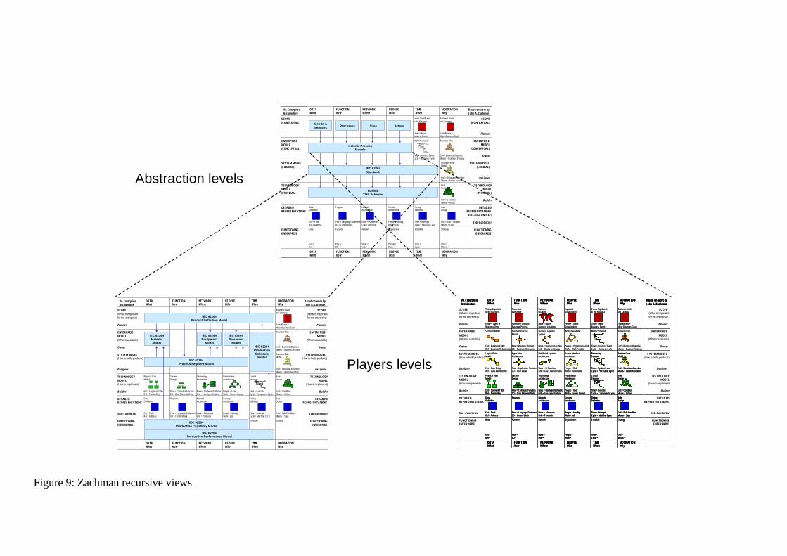
cycle, for ensuring traceability. As Sowa and Zachman (1992) pointed out: the recursiveness
of the framework is possible. It is the possibility of applying the logic of the framework to the
framework itself. That is, any given cell is a complex engineering product in its own right. It
has an owner, designer, builder, material, function, and geometry. Therefore, the framework
logic could be applied to each of the cells of the framework (or rows) to analyse the design
and construction issues that affect that cell (that row) with a new perspective related to the
players view (Figure 9). The player view is recursively a Zachman matrix related to one cell
(or row) of the initial matrix
Based on work by John A. Zachman
VA Enterprise Architecture
DATAWhat
FUNCTIONHow
NETWORKWhere
PEOPLEWho
TIMEWhen
MOTIVATIONWhy
DATAWhat
FUNCTIONHow
NETWORKWhere
PEOPLEWho
TIMEWhen
MOTIVATIONWhy
SCOPE(CONTEXTUAL)
ENTERPRISEMODEL(CONCEPTUAL)
SYSTEM MODEL(LOGICAL)
TECHNOLOGYMODEL(PHYSICAL)
DETAILEDREPRESENTATIONS
FUNCTIONINGENTERPRISE
SCOPE(CONTEXTUAL)
Planner
ENTERPRISEMODEL
(CONCEPTUAL)
Owner
SYSTEM MODEL(LOGICAL)
Designer
TECHNOLOGYMODEL
(PHYSICAL)
Builder
DETAILEDREPRESENTATIONS(OUT-OF-CONTEXT)
Sub-Contractor
FUNCTIONINGENTERPRISE
Master Schedule
Time = Business Event Cycle = Business Cycle
Business Plan
End = Business Objective Means = Business Strategy
Events Significantto the Business
Time = MajorBusiness Event
Business Goalsand Strategy
Ends/Means =Major Business Goals
Business RuleModel
End = Structural Assertion Means = Action Assertion
RuleDesign
End = Condition Means = Action
DataDefinition
Ent = Field Rel = Address
Program
Proc = Language StatementI/O = Control Block
NetworkArchitecture
Node = AddressesLink = Protocols
SecurityArchitecture
People = IdentityWork = Job
Timing Definition
Time = InterruptCycle = Machine Cycle
RuleDesign
End = Sub -Condition Means = Step
Data
Ent = Rel =
Function
Proc =I/O =
Network
Node = Link =
Organization
People = Work =
Schedule
Time = Cycle =
Strategy
End = Means =
IEC 62264Standards
Holonic ProcessModels
B2MMLXML Schemas
Goods &Services Processes Sites Actors
Abstraction levels
Players levels
Based on work by John A. Zachman
VA Enterprise Architecture
DATAWhat
FUNCTIONHow
NETWORKWhere
PEOPLEWho
TIMEWhen
MOTIVATIONWhy
DATAWhat
FUNCTIONHow
NETWORKWhere
PEOPLEWho
TIMEWhen
MOTIVATIONWhy
SCOPE(What is importantfor the enterprise)
Planner
ENTERPRISEMODEL(What is available)
Owner
SYSTEM MODEL(How to build products)
Designer
TECHNOLOGYMODEL(How to implement)
Builder
DETAILEDREPRESENTATIONS
Sub-Contractor
FUNCTIONINGENTERPRISE
SCOPE(What is importantfor the enterprise)
Planner
ENTERPRISEMODEL
(What is available)
Owner
SYSTEM MODEL(How to build products)
Designer
TECHNOLOGYMODEL
(How to implement)
Builder
DETAILEDREPRESENTATIONS
Sub-Contractor
FUNCTIONINGENTERPRISE
Business Plan
End = Business Objective Means = Business Strategy
Business Goalsand Strategy
Ends/Means =Major Business Goals
Business RuleModel
End = Structural Assertion Means = Action Assertion
Physical DataModel
Ent = Segment/Table Rel = Pointer/Key
SystemDesign
Proc = Computer FunctionI/O = Data Elements/Sets
TechnologyArchitecture
Node = Hardware/Software Link = Line Specifications
PresentationArchitecture
People = User Work = Screen Format
ControlStructure
Time = ExecuteCycle = Component Cycle
RuleDesign
End = Condition Means = Action
DataDefinition
Ent = Field Rel = Address
Program
Proc = Language StatementI/O = Control Block
NetworkArchitecture
Node = AddressesLink = Protocols
SecurityArchitecture
People = IdentityWork = Job
Timing Definition
Time = InterruptCycle = Machine Cycle
RuleDesign
End = Sub -Condition Means = Step
Schedule Strategy
IEC 62264Material Model
IEC 62264Personnel
Model
IEC 62264Product Definition Model
IEC 62264Equipment
ModelIEC 62264
Production Schedule
Model
IEC 62264Production Capability Model
IEC 62264Process Segment Model
IEC 62264Production Performance Model
Based on work by John A. Zachman
VA Enterprise Architecture
DATAWhat
FUNCTIONHow
NETWORKWhere
PEOPLEWho
TIMEWhen
MOTIVATIONWhy
DATAWhat
FUNCTIONHow
NETWORKWhere
PEOPLEWho
TIMEWhen
MOTIVATIONWhy
SCOPE(What is importantfor the enterprise)
Planner
ENTERPRISEMODEL(What is available)
Owner
SYSTEM MODEL(How to build products)
Designer
TECHNOLOGYMODEL(How to implement)
Builder
DETAILEDREPRESENTATIONS
Sub-Contractor
FUNCTIONINGENTERPRISE
SCOPE(What is importantfor the enterprise)
Planner
ENTERPRISEMODEL
(What is available)
Owner
SYSTEM MODEL(How to build products)
Designer
TECHNOLOGYMODEL
(How to implement)
Builder
DETAILEDREPRESENTATIONS
Sub-Contractor
FUNCTIONINGENTERPRISE
Things Important to the Business
Entity = Class of Business Thing
ProcessesPerformed
Function = Class of Business Process
Semantic Model
Ent = Business EntityRel = Business Relationship
Business ProcessModel
Proc = Business ProcessI/O = Business Resources
Business LogisticsSystem
Node = Business Location Link = Business Linkage
Work Flow Model
People = Organization Unit Work = Work Product
Master Schedule
Time = Business Event Cycle = Business Cycle
Business Plan
End = Business Objective Means = Business Strategy
ImportantOrganizations
People = Major Organizations
Business locations
Node = Major Business Locations
Events Significantto the Business
Time = MajorBusiness Event
Business Goalsand Strategy
Ends/Means =Major Business Goals
Logical DataModel
Ent = Data EntityRel = Data Relationship
Application Architecture
Proc = Application FunctionI/O = User Views
Distributed SystemArchitecture
Node = IS FunctionLink = Line Characteristics
Human InterfaceArchitecture
People = RoleWork = Deliverable
ProcessingStructure
Time = System Event Cycle = Processing Cycle
Business RuleModel
End = Structural Assertion Means = Action Assertion
Physical DataModel
Ent = Segment/Table Rel = Pointer/Key
SystemDesign
Proc = Computer FunctionI/O = Data Elements/Sets
TechnologyArchitecture
Node = Hardware/Software Link = Line Specifications
PresentationArchitecture
People = User Work = Screen Format
ControlStructure
Time = ExecuteCycle = Component Cycle
RuleDesign
End = Condition Means = Action
DataDefinition
Ent = Field Rel = Address
Program
Proc = Language StatementI/O = Control Block
NetworkArchitecture
Node = AddressesLink = Protocols
SecurityArchitecture
People = IdentityWork = Job
Timing Definition
Time = InterruptCycle = Machine Cycle
RuleDesign
End = Sub -Condition Means = Step
Data
Ent = Rel =
Function
Proc =I/O =
Network
Node = Link =
Organization
People = Work =
Schedule
Time = Cycle =
Strategy
End = Means =
Based on work by John A. Zachman
VA Enterprise Architecture
DATAWhat
FUNCTIONHow
NETWORKWhere
PEOPLEWho
TIMEWhen
MOTIVATIONWhy
DATAWhat
FUNCTIONHow
NETWORKWhere
PEOPLEWho
TIMEWhen
Based on work by John A. Zachman
VA Enterprise Architecture
DATAWhat
FUNCTIONHow
NETWORKWhere
PEOPLEWho
TIMEWhen
MOTIVATIONWhy
DATAWhat
FUNCTIONHow
NETWORKWhere
PEOPLEWho
TIMEWhen
MOTIVATIONWhy
- -
Things Important to the Business
Entity = Class of Business Thing
ProcessesPerformed
Function = Class of Business Process
Semantic Model
Ent = Business EntityRel = Business Relationship
Business ProcessModel
Proc = Business ProcessI/O = Business Resources
Business LogisticsSystem
Node = Business Location Link = Business Linkage
Work Flow Model
People = Organization Unit Work = Work Product
Master Schedule
Time = Business Event Cycle = Business Cycle
Business Plan
End = Business Objective Means = Business Strategy
ImportantOrganizations
People = Major Organizations
Business locations
Node = Major Business Locations
Events Significantto the Business
Time = MajorBusiness Event
Business Goalsand Strategy
Ends/Means =Major Business Goals
Logical DataModel
Ent = Data EntityRel = Data Relationship
Application Architecture
Proc = Application FunctionI/O = User Views
Distributed SystemArchitecture
Node = IS FunctionLink = Line Characteristics
Human InterfaceArchitecture
People = RoleWork = Deliverable
ProcessingStructure
Time = System Event Cycle = Processing Cycle
Business RuleModel
End = Structural Assertion Means = Action Assertion
Physical DataModel
Ent = Segment/Table Rel = Pointer/Key
SystemDesign
Proc = Computer FunctionI/O = Data Elements/Sets
TechnologyArchitecture
Node = Hardware/Software Link = Line Specifications
PresentationArchitecture
People = User Work = Screen Format
ControlStructure
Time = ExecuteCycle = Component Cycle
RuleDesign
End = Condition Means = Action
DataDefinition
Ent = Field Rel = Address
Program
Proc = Language StatementI/O = Control Block
NetworkArchitecture
Node = AddressesLink = Protocols
SecurityArchitecture
People = IdentityWork = Job
Timing Definition
Time = InterruptCycle = Machine Cycle
RuleDesign
End = Sub -Condition Means = Step
Data
Ent = Rel =
Function
Proc =I/O =
Network
Node = Link =
Organization
People = Work =
Schedule
Time = Cycle =
Strategy
End = Means =
People = IdentityWork = Job
Timing Definition
Time = InterruptCycle = Machine Cycle
RuleDesign
End = Sub -Condition Means = Step
Data
Ent = Rel =
Function
Proc =I/O =
Network
Node = Link =
Organization
People = Work =
Schedule
Time = Cycle =
Strategy
End = Means =
Figure 9: Zachman recursive views
Panetto H., Baïna, S., Morel G. (2007). Mapping the IEC 62264 models onto the Zachman framework for analysing products information traceability: a case study. Journal of Intelligent Manufacturing, Springer Verlag, ISSN 0956-5515, à paraître
-19-
Indeed, Sowa and Zachman (1992) proposed a set of rules when using their framework. The
logic structure or rules of the framework are generic. They can be used for structuring the
description of any complex object. The framework was first discovered by observing how the
manufacturing discipline segments the descriptions of complex engineering products for the
purpose of design and manufacture. Two of these rules strengthen the recursive perspective
of the framework:
• The composite or integration of all cell models in one row constitutes a complete
model from the perspective of that row.
• The logic is recursive. The framework logic can be used for describing virtually
anything, certainly anything that has an owner, designer, and builder who makes
use of material, function, and geometry. The logic was initially perceived by
observing the design and construction of buildings.
Thus, the Zachman framework could be seen as a way to define different models at different
abstract levels, for different purposes, or, as a filter that enables, through different views, to
specify what has to be modelled in relation to the player in the IT organisation. The
framework will then support a kind of methodology when one would like to instantiate a set
of related models such as the IEC 62264 standard. The result will be a better formalisation
about what each model is dealing with and the relationships between them with regards to a
specific need: in our case, the modelling of product information traceability.
We then take into account mainly the players’ view of the models who will be guided by the
framework to ensure that all aspects involved in product information traceability have been
taken into account during the modelling phase. Indeed, we mapped the eight IEC 62264
models onto the framework and, we defined some preliminary logical relationships between
them in order to facilitate the definition of the product information traceability (Figure 10).

Based on work by John A. Zachman
VA Enterprise Architecture
DATAWhat
FUNCTIONHow
NETWORKWhere
PEOPLEWho
TIMEWhen
MOTIVATIONWhy
DATAWhat
FUNCTIONHow
NETWORKWhere
PEOPLEWho
TIMEWhen
MOTIVATIONWhy
SCOPE(What is importantfor the enterprise)
Planner
ENTERPRISEMODEL(What is available)
Owner
SYSTEM MODEL(How to build products)
Designer
TECHNOLOGYMODEL(How to implement)
Builder
DETAILEDREPRESENTATIONS
Sub-Contractor
FUNCTIONINGENTERPRISE
SCOPE(What is importantfor the enterprise)
Planner
ENTERPRISEMODEL
(What is available)
Owner
SYSTEM MODEL(How to build products)
Designer
TECHNOLOGYMODEL
(How to implement)
Builder
DETAILEDREPRESENTATIONS
Sub-Contractor
FUNCTIONINGENTERPRISE
Business Plan
End = Business Objective Means = Business Strategy
Business Goalsand Strategy
Ends/Means =Major Business Goals
Business RuleModel
End = Structural Assertion Means = Action Assertion
Physical DataModel
Ent = Segment/Table Rel = Pointer/Key
SystemDesign
Proc = Computer FunctionI/O = Data Elements/Sets
TechnologyArchitecture
Node = Hardware/Software Link = Line Specifications
PresentationArchitecture
People = User Work = Screen Format
ControlStructure
Time = ExecuteCycle = Component Cycle
RuleDesign
End = Condition Means = Action
DataDefinition
Ent = Field Rel = Address
Program
Proc = Language StatementI/O = Control Block
NetworkArchitecture
Node = AddressesLink = Protocols
SecurityArchitecture
People = IdentityWork = Job
Timing Definition
Time = InterruptCycle = Machine Cycle
RuleDesign
End = Sub -Condition Means = Step
Schedule Strategy
IEC 62264Material Model
IEC 62264Personnel
Model
IEC 62264Product Definition Model
IEC 62264Equipment
ModelIEC 62264
Production Schedule
Model
IEC 62264Production Capability Model
IEC 62264Process Segment Model
IEC 62264Production Performance Model
Figure 10: IEC 62264 models mapped onto the Zachman framework players view
Let us now explain, line by line, model by model, what our mapping will bring. In Figure 10,
the arrows have the semantics of “has a reference to”; for example, the “Product Definition
Model” has references to the “Material Model”, the “Equipment Model”, the “Personnel
Model” and the “Process Segment Model”.
The first line of the framework, related to the planner view, concerns the things that define
the nature and purpose of the enterprise and what is important for the enterprise. It is related
to the product definition and the needed resource specifications. This is exactly the definition
of the IEC 62264 “Product definition model” that defines product segments which identify
the products, their location, their references, and the resources needed to produce them. The
second line defines the enterprise model comprised of the nature of the available
manufacturing and business components including the structure, functions and organization.
The IEC 62264 specifies the enterprise model by hierarchies related to the materials (raw,
consumed, finished …), the equipment and the personnel available for production. The
product definition reference resources as needed for specific products while the process
Panetto H., Baïna, S., Morel G. (2007). Mapping the IEC 62264 models onto the Zachman framework for analysing products information traceability: a case study. Journal of Intelligent Manufacturing, Springer Verlag, ISSN 0956-5515, à paraître
-21-
segments reference them as available resources for production. The third line of the
framework, related to the designer view, defines the available processes and their information
process and how to build products. In our context, this level relates to the process segments
that list the classes of personnel, equipment, and material needed, and/or present specific
resources, such as specific equipment needed. The scheduling and decomposition of process
segments with regards to the available resources is specified, in IEC 62264, by the
“Production Schedule Model” that crosses the second and third lines of the framework.
Indeed, scheduling means synchronising resource availability and product definitions in order
to deal with time constraints. The fourth and fifth lines of the framework are out of our scope
with regards to product traceability. Indeed, they relate to the builder view and its sub-
contractors and are used for defining the system development process.
Finally, the “Functioning Enterprise” line of the framework, which is usually forgotten by
modellers, is important for our scope because it defines how real time information related to
the production capability and production performance is modelled in relationship with the
enterprise model and the production schedule. It is the place where most of the information is
produced in order to record the product genealogy and its life history.
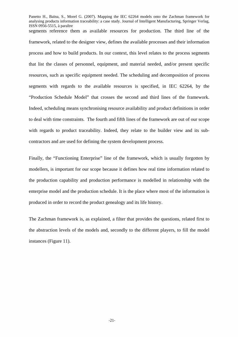
The Zachman framework is, as explained, a filter that provides the questions, related first to
the abstraction levels of the models and, secondly to the different players, to fill the model
instances (Figure 11).
P ro d uc ts i nfo rma ti o n tra c e a b il ity
Fo rwa rd tra c e a b il ity
B a c k wa rd tra c e a b i l ity
Abstraction view Players view
Figure 11: The Zachman framework as a filter for views definition of products information traceability models.
Panetto H., Baïna, S., Morel G. (2007). Mapping the IEC 62264 models onto the Zachman framework for analysing products information traceability: a case study. Journal of Intelligent Manufacturing, Springer Verlag, ISSN 0956-5515, à paraître
-23-
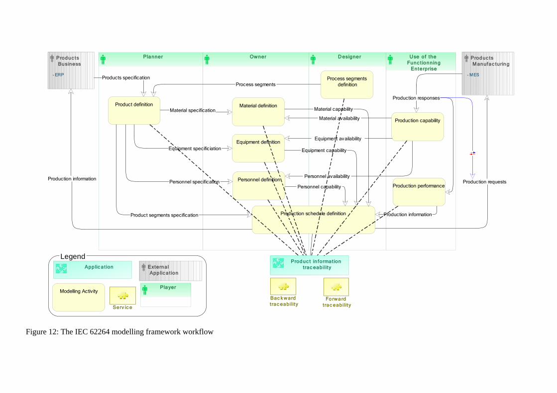
Zachman does not advocate the use of any particular modelling style and the framework
offers only a static overview of all elements involved in information systems. Then, in order
to understand the many relationships existing among the models and thus facilitating their
instantiation, the framework and our proposed mapping have to be completed by the
workflow presented on Figure 12 that shows the information provided by each model and
used by others. It represents a dynamic view related to a development project the IEC 62264
models have instantiated. The product information traceability application (comprising the
two services related to backward and forward traceability (see section 2) is then fulfilled by
merging the information coming from all IEC 62264 models, each of them related to different
key players in the enterprise together with real-time information coming from the functioning
enterprise.
The next section applies our approach to a case study related to an enterprise that makes and
packs bags of flour. That enterprise needs a better traceability of their products in order to
better improve customers’ relationships when a defect happens in the flour making process.
Use of the Func t ionning
Enterprise
D esignerOwnerPlannerProduc ts Business
- ERP
Produc ts Manufac turing
- M ESProducts specification
Product definitionMaterial specification
Equipment specificiation
Personnel specification
Material definition
Equipment definition
Personnel definition
Product segments specification Production schedule definition
Personnel capability
Equipment capability
Material capability
Process segments definition
Production capabilityMaterial availability
Equipment availability
Personnel availability
Production responses
Production information
Process segments
Production requests
Produc t in formation trac eability
Forward t rac eability
Bac k ward t rac eability
Applic a t ion
Modelling Activity
External App lic a t ion
Player
Serv ic e
Legend
Production performanceProduction information
Figure 12: The IEC 62264 modelling framework workflow
Panetto H., Baïna, S., Morel G. (2007). Mapping the IEC 62264 models onto the Zachman framework for analysing products information traceability: a case study. Journal of Intelligent Manufacturing, Springer Verlag, ISSN 0956-5515, à paraître
-25-
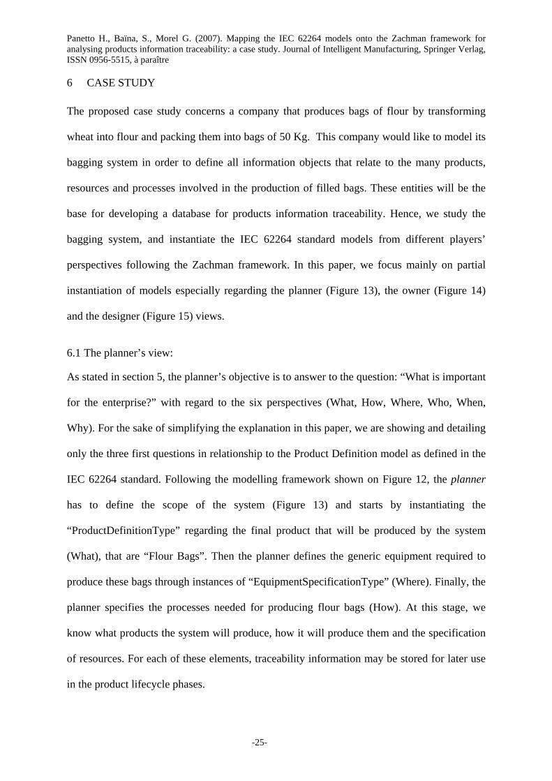
6 CASE STUDY
The proposed case study concerns a company that produces bags of flour by transforming
wheat into flour and packing them into bags of 50 Kg. This company would like to model its
bagging system in order to define all information objects that relate to the many products,
resources and processes involved in the production of filled bags. These entities will be the
base for developing a database for products information traceability. Hence, we study the
bagging system, and instantiate the IEC 62264 standard models from different players’
perspectives following the Zachman framework. In this paper, we focus mainly on partial
instantiation of models especially regarding the planner (Figure 13), the owner (Figure 14)
and the designer (Figure 15) views.
6.1 The planner’s view:
As stated in section 5, the planner’s objective is to answer to the question: “What is important
for the enterprise?” with regard to the six perspectives (What, How, Where, Who, When,
Why). For the sake of simplifying the explanation in this paper, we are showing and detailing
only the three first questions in relationship to the Product Definition model as defined in the
IEC 62264 standard. Following the modelling framework shown on Figure 12, the planner
has to define the scope of the system (Figure 13) and starts by instantiating the
“ProductDefinitionType” regarding the final product that will be produced by the system
(What), that are “Flour Bags”. Then the planner defines the generic equipment required to
produce these bags through instances of “EquipmentSpecificationType” (Where). Finally, the
planner specifies the processes needed for producing flour bags (How). At this stage, we
know what products the system will produce, how it will produce them and the specification
of resources. For each of these elements, traceability information may be stored for later use
in the product lifecycle phases.
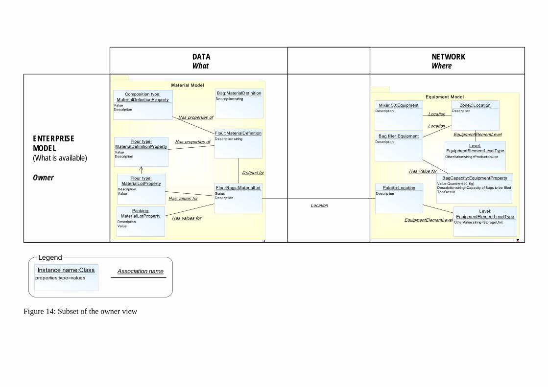
6.2 The owner’s view:
The owner of the system has now to specify the enterprise model (Figure 14) defining the
specific resources hierarchies available for this system. These resources are materials (raw,
finished …) (What), equipment and locations (Where) and People (Who). Materials are
instances of “MaterialDefinition” that link to instances of “MaterialDefinitionProperty”
which characterise them. Equipment are instances of “Equipment” that link to instances of
“EquipmentProperty” and “Location”. These instances are then linked to the specifications
defined by the planner to map the planner requirements with the system available resources.
The resulting model then specifies the resources (materials, equipments) available to produce.
Each of those resources has properties that are stored for traceability purpose.
6.3 The designer’s view:
Finally, the system designer should have (or will have) built the system in order to allow the
production of different kind of products and, then shall model (Figure 15) the system
processes (“ProcessSegmentType”), their inputs (consumed materials) and outputs (produced
materials) (“SegmentSpecificationMaterial”), the supported equipments (“Segment-
SpecificationEquipment”) and people (“SegmentSpecificationPersonnel”). These resources
are linked to the available resources as defined by the owner in the enterprise model. The
resulting model is, of course, linked to the owner model (enterprise model) but also records
traceability information related to the different products instances that are produced by the
system.
All these instances of IEC 62264 models will then define a conceptual model that may be
derived to produce a relational model for implementing a database to record information
regarding the products, the processes and the resources along the product lifecycle in order to
provide both forward and backward information traceability (see section 2).

Panetto H., Baïna, S., Morel G. (2007). Mapping the IEC 62264 models onto the Zachman framework for analysing products information traceability: a case study. Journal of Intelligent Manufacturing, Springer Verlag, ISSN 0956-5515, à paraître
-27-
Equipment Model
Produc t Def init ion
Flour Bag:ProductDefinitionType
PublishedDateVersionDescription
Fill a Bag:ProductSegmentType
DescriptionDurationParameter
Has associated
Prepare Flour:ProductSegmentType
DescriptionDurationParameter
PrepFull:ProductSegmentDependencyOtherValue:string=AfterEnd
Has an execution dependency on
Bag filler:EquipmentSpecificationTypeQuantity:Quantity={50, Kg}Description
Equipment specification
Mixer:EquipmentSpecificationType
DescriptionQuantity:Quantity
Equipment specification
Mixer 50:EquipmentDescription
Equipment
Bag filler:EquipmentDescription
Equipment
DATAWhat
NETWORKWhere
SCOPE(What is importantfor the enterprise)
Planner
FUNCTIONHow
Figure 13: Subset of the planner view
Instance name:Classproperties:type=values
Association name
Legend
Equipment Model
Mater ial Model
Flour:MaterialDefinitionDescription:string
FlourBags:MaterialLotStatusDescription
Defined by
Composition type:MaterialDefinitionProperty
ValueDescription
Has properties of
Flour type:MaterialDefinitionPropertyValueDescription
Has properties of
Packing:MaterialLotProperty
DescriptionValue
Has values for
Flour type:MaterialLotProperty
DescriptionValue
Has values for
Palette:LocationDescription
EquipmentElementLevel
Location
Mixer 50:EquipmentDescription
Zone2:LocationDescription
Level:EquipmentElementLevelType
OtherValue:string=ProductionLIne
EquipmentElementLevel
Location
Bag filler:EquipmentDescription
Location
Has Value for
Bag:MaterialDefinitionDescription:string
Level:EquipmentElementLevelType
OtherValue:string=StorageUnit
BagCapacity:EquipmentPropertyValue:Quantity={50, Kg}Description:string=Capacity of Bags to be filledTestResult
ENTERPRISEMODEL(What is available)
Owner
DATAWhat
NETWORKWhere
Figure 14: Subset of the owner view
Instance name:Classproperties:type=values
Association name
Legend

Panetto H., Baïna, S., Morel G. (2007). Mapping the IEC 62264 models onto the Zachman framework for analysing products information traceability: a case study. Journal of Intelligent Manufacturing, Springer Verlag, ISSN 0956-5515, à paraître
-29-
Mater ial Model Equipment Model
Process Segment
Fill Bags:ProcessSegmentType
ParameterDescriptionPublishedDateDuration
Bag:MaterialSegmentSpecification
TypeMaterialUse:string=ConsumedQuantity:Quantity=1Description
Bag:MaterialDefinitionDescription:string
MaterialDefinition
Flour:MaterialSegmentSpecification
TypeMaterialUse:string=ConsumedQuantity:Quantity={50, Kg}Description
Flour:MaterialDefinitionDescription:string
MaterialDefinition
MaterialSegmentSpecification
MaterialSegmentSpecification
FlourBag:MaterialSegmentSpecification
TypeMaterialUse:string=ProducedQuantity:Quantity=1Description
MaterialSegmentSpecification
Bag filler:EquipmentSegmentSpecification
TypeDescriptionQuantity
EquipmentSegmentSpecification
Equipment
Corbeil:LocationDescription
Level:EquipmentElementLevel
TypeOtherValue:string=Site
EquipmentElementLevel
Location
Bag filler:EquipmentDescription
DATAWhat
NETWORKWhere
FUNCTIONHow
SYSTEM MODEL(How to build products)
Designer
Figure 15: Subset of the designer view
Instance name:Classproperties:type=values
Association name
Legend

The current instantiation of the IEC 62264 models is then used as the base for feeding a
product information traceability database implementing the standard. This implementation is
based on the B2MML (Business To Manufacturing Markup Language)1 developed by the
World Batch Forum. The Zachman Functioning View models the runtime information
retrieval from the manufacturing processes (Production capability and performance models)
that fills the database for enabling both backward and forward traceability services.
7 CONCLUSION
The paper proposed a mapping of IEC 62264 standard models onto the Zachman framework.
The objective was, based on the recursiveness of the framework, to define a specific
perspective of the framework dealing with the players view. The framework is not strict and
rigid but there is the possibility of applying the logic of the framework to the framework itself,
recursively at each abstraction level (Sowa and Zachman, 1992).
The IEC 62264 standard models are complex because they are generic to any kind of
application domains. Thus, our approach and methodology helps modellers to understand
these domains and facilitate their instantiation. The Zachman framework proposes general
views about what a player should take into account when developing a system but its views
need to be made concrete by mapping each row on specific models. Our mapping together
with a modelling framework workflow then defines a methodology and a systematic
approach. This approach supports the different players in the product and process modelling
for instantiating the IEC 62264 models. It then defines product lifecycle information models
for traceability. The result of this modelling approach is the emergence of all information
objects that deal with product information along its life cycle.
We applied our proposed methodology to an industrial case study showing then its
practicability and completeness. Our ongoing work is to populate a database implementing
the standard with the information objects coming from this application.
1 B2MML : Business To Manufacturing Markup Language, World Batch Forun, http://www.wbf.org
Panetto H., Baïna, S., Morel G. (2007). Mapping the IEC 62264 models onto the Zachman framework for analysing products information traceability: a case study. Journal of Intelligent Manufacturing, Springer Verlag, ISSN 0956-5515, à paraître
-31-
8 REFERENCES
Baïna S., Panetto H., and Morel G. (2005), Holon-oriented B2M process modelling approach
for applications interoperability in manufacturing systems environment, Proceedings of
the IFAC World Congress, July 4-7, Prague, Czech Republic, ISBN: 0-08-045108-X
Bézivin J. (2004). In search of a Basic Principle for Model Driven Engineering,
Novatica/Upgrade, Vol. V, N°2, April, pp. 21-24, http://www.upgrade-
cepis.org/issues/2004/2/upgrade-vol-V-2.html
Cheng M.L. and Simmons J. E. L. (1994). Traceability in manufacturing systems.
International Journal of Operations and Production Management, 14, 4-16
C4ISR Architecture Framework Version 2.0 (1997). Office of the Assistant Secretary of
Defense for Command, Control, Communications and Intelligence, Washington D.C.,
November
delaHostria E. (2005). Manufacturing Application Integration Scheme using ISO 15745 and
IEC 62264. Proceedings of the IFAC World Congress, July 4-7, Prague, Czech Republic,
ISBN: 0-08-045108-X
IEC 62264 (2002). IEC 62264. Enterprise-control system integration, Part 1. Models and
terminology, Part 2: Model object attributes. ISO/IEC, Geneva
ISO IS 15704 (2000). ISO/IS 15704:2000 Industrial automation systems—Requirements for
enterprise—reference architectures and methodologies, ISO, Geneva, Switzerland
ISO 15745-1, (2003) Industrial automation systems and integration – Open systems
application integration framework - Part 1: Generic reference description. ISO, Geneva,
Switzerland
Frankel D. S., et al. (2003). The Zachman Framework and the OMG's Model Driven
Architecture. Business Process Trends Whitepaper, September, http://www.bptrends.com
Jansen-Vullers J., van Dorp A., and Beulens B. (2003). Managing traceability information in
manufacture, International Journal of Information Management, 23, 395-413
McFarlane D., Sarma J., Chirn G., Wong J., Ashton A. (2003). Auto-ID systems and
intelligent manufacturing control, Journal of Engineering Applications of Artificial
Intelligence, 16, 365 – 376
Mellor S.J., Kendall S., Uhl A. and Weise D. (2004). Model Driven Architecture, Addison-
Wesley Pub Co, March, ISBN: 0201788918.
Morel G., Panetto H., Zaremba M.B. and Mayer F. (2003). Manufacturing Enterprise Control
and Management System Engineering: paradigms and open issues. IFAC Annual Reviews
in Control. 27/2:199-209, December
Noran O. (2003). An analysis of the Zachman framework for enterprise architecture from the
GERAM perspective. IFAC Annual Reviews in Control. 27/2:163-183, December
Osvalds G. (2003). Use of UML in Modeling Enterprise and Systems Architecture. INCOSE
Chesapeake Chapter Meeting, Columbia, August
O'Rourke C., Fishman N. and Selkow W. (2003). Enterprise Architecture Using the Zachman
Framework,, Thomson Learning, Inc. Boston, MA. ISBN: 0-619-06446-3. April
Sowa J. F. and Zachman J. A. (1992). Extending and Formalizing the Framework for
Information Systems Architecture, IBM Systems Journal, 31/3, 590–616
Sowell P. K. (1999). Consolidated Mapping of C4ISR Framework Products to Federal
Framework Models. The MITRE Corporation, McLean, Virginia.
Terzi S. (2005). Elements of Product Lifecycle Management: Definitions, Open Issues and
Reference Models, PhD dissertation, University Henri Poincaré Nancy I and Politecnico
di Milano, May 25th
Terzi S., Cassina J., and Panetto H. (2005). Development of a metamodel to foster
interoperability along the product lifecycle traceability. Proceedings of the IFIP/ACM
INTEROP-ESA conference, February 23-25, Geneva, Switzerland, Springer Science
publisher, pp. 1-11, ISBN: 1-84628-151-2
UML (2005). Unified Modeling Language. UML 2.0 Superstructure, v2.0 formal 05/07/04.
OMG
Panetto H., Baïna, S., Morel G. (2007). Mapping the IEC 62264 models onto the Zachman framework for analysing products information traceability: a case study. Journal of Intelligent Manufacturing, Springer Verlag, ISSN 0956-5515, à paraître
-33-
Zachman J. A. (1987). A Framework for Information Systems Architecture, IBM Systems
Journal, 26/3, 276–295
ACKNOWLEDGEMENT
The authors would like to thank the enterprise Groupe Soufflet, and more specially Françoise
Entzmann, for the application support used in this work.
List of figures
Figure 1: Product-centric paradigm (adapted from (Baïna, et al., 2005)...................................4 Figure 2: Functional hierarchy as defined in IEC 62264...........................................................7 Figure 3: The IEC 62264 models hierarchy (IEC 62264, 2002)................................................8 Figure 4: The UML class diagram formalism..........................................................................11 Figure 5: The conceptualised IEC 62264 Product Definition model.......................................12 Figure 6: The conceptualised IEC 62264 Material model .......................................................13 Figure 7: The Zachman framework matrix..............................................................................14 Figure 8: IEC 62264 standards on the Zachman abstraction view ..........................................16 Figure 9: Zachman recursive views .........................................................................................18 Figure 10: IEC 62264 models mapped onto the Zachman framework players view...............20 Figure 11: The Zachman framework as a filter for views definition of products information traceability models. ..................................................................................................................22 Figure 12: The IEC 62264 modelling framework workflow...................................................24 Figure 13: Subset of the planner view .....................................................................................27 Figure 14: Subset of the owner view .......................................................................................28 Figure 15: Subset of the designer view....................................................................................29


