Download - Manufacturing Process - NCET
Manufacturing Process
Dept of Mechanical Engineering 1
MANUFACTURING PROCESS
The process of converting raw materials, components, or parts into finished goods that meet a
customer's expectations or specifications is known as manufacturing process. Manufacturing
commonly employs a man-machine setup with division of labor in a large scale production.
CLASSIFICATION OF MACHINING PROCESS:
The manufacturing processes can be classified as:
1. Forming Processes
2. Moulding Processes
3. Machining Processes
4. Assembly Processes
5. Finishing Processes.
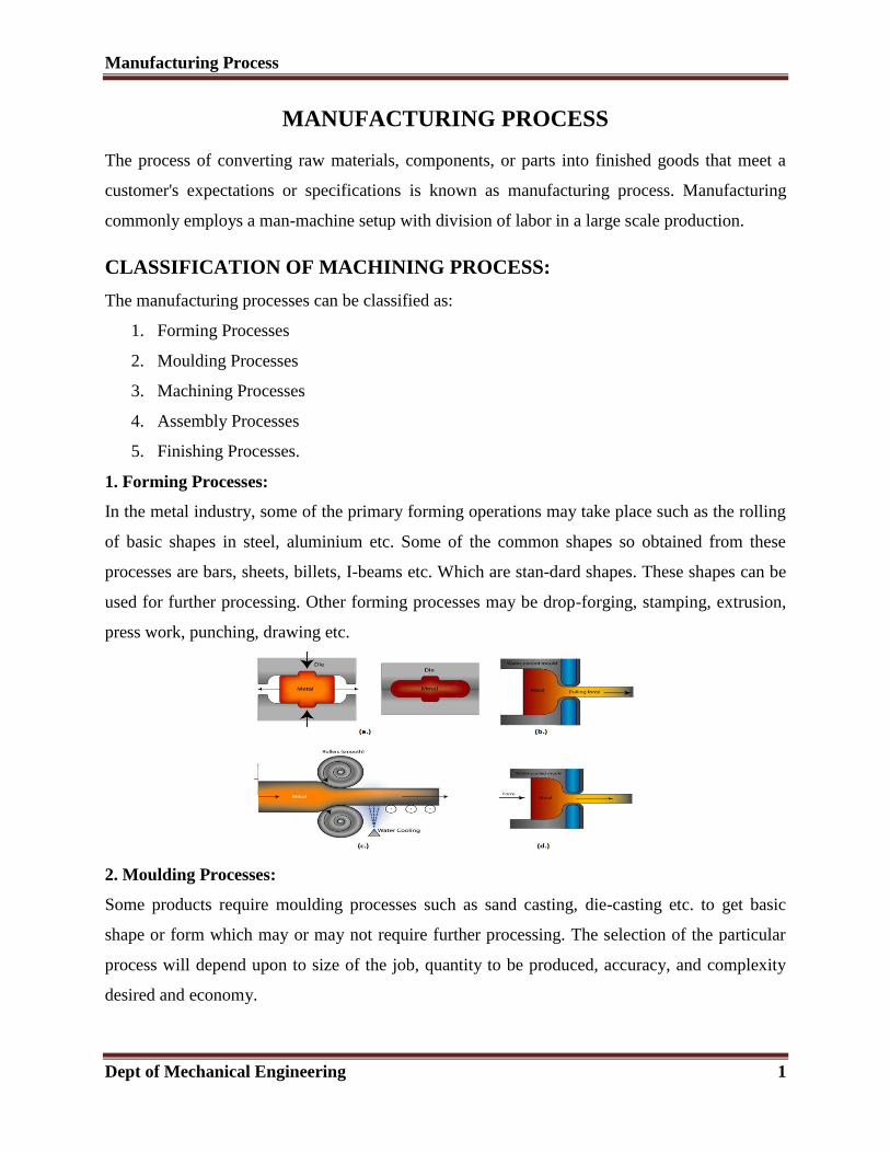
1. Forming Processes:
In the metal industry, some of the primary forming operations may take place such as the rolling
of basic shapes in steel, aluminium etc. Some of the common shapes so obtained from these
processes are bars, sheets, billets, I-beams etc. Which are standard shapes. These shapes can be
used for further processing. Other forming processes may be drop-forging, stamping, extrusion,
press work, punching, drawing etc.
2. Moulding Processes:
Some products require moulding processes such as sand casting, die-casting etc. to get basic
shape or form which may or may not require further processing. The selection of the particular
process will depend upon to size of the job, quantity to be produced, accuracy, and complexity
desired and economy.
Manufacturing Process
Dept of Mechanical Engineering 2
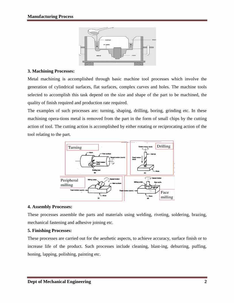
3. Machining Processes:
Metal machining is accomplished through basic machine tool processes which involve the
generation of cylindrical surfaces, flat surfaces, complex curves and holes. The machine tools
selected to accomplish this task depend on the size and shape of the part to be machined, the
quality of finish required and production rate required.
The examples of such processes are: turning, shaping, drilling, boring, grinding etc. In these
machining operations metal is removed from the part in the form of small chips by the cutting
action of tool. The cutting action is accomplished by either rotating or reciprocating action of the
tool relating to the part.
4. Assembly Processes:
These processes assemble the parts and materials using welding, riveting, soldering, brazing,
mechanical fastening and adhesive joining etc.
5. Finishing Processes:
These processes are carried out for the aesthetic aspects, to achieve accuracy, surface finish or to
increase life of the product. Such processes include cleaning, blasting, deburring, puffing,
honing, lapping, polishing, painting etc.
Manufacturing Process
Dept of Mechanical Engineering 3
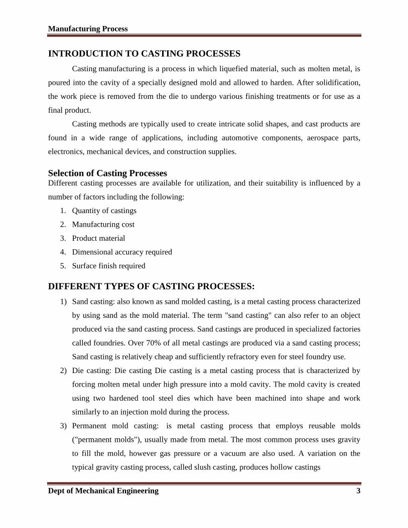
INTRODUCTION TO CASTING PROCESSES
Casting manufacturing is a process in which liquefied material, such as molten metal, is
poured into the cavity of a specially designed mold and allowed to harden. After solidification,
the work piece is removed from the die to undergo various finishing treatments or for use as a
final product.
Casting methods are typically used to create intricate solid shapes, and cast products are
found in a wide range of applications, including automotive components, aerospace parts,
electronics, mechanical devices, and construction supplies.
Selection of Casting Processes Different casting processes are available for utilization, and their suitability is influenced by a
number of factors including the following:
1. Quantity of castings
2. Manufacturing cost
3. Product material
4. Dimensional accuracy required
5. Surface finish required
DIFFERENT TYPES OF CASTING PROCESSES:
1) Sand casting: also known as sand molded casting, is a metal casting process characterized
by using sand as the mold material. The term "sand casting" can also refer to an object
produced via the sand casting process. Sand castings are produced in specialized factories
called foundries. Over 70% of all metal castings are produced via a sand casting process;
Sand casting is relatively cheap and sufficiently refractory even for steel foundry use.
2) Die casting: Die casting Die casting is a metal casting process that is characterized by
forcing molten metal under high pressure into a mold cavity. The mold cavity is created
using two hardened tool steel dies which have been machined into shape and work
similarly to an injection mold during the process.
3) Permanent mold casting: is metal casting process that employs reusable molds
("permanent molds"), usually made from metal. The most common process uses gravity
to fill the mold, however gas pressure or a vacuum are also used. A variation on the
typical gravity casting process, called slush casting, produces hollow castings
Manufacturing Process
Dept of Mechanical Engineering 4
4) Investment casting: is an industrial process based on and also called lost-wax casting, one
of the oldest known metal-forming techniques .From 5,000 years ago, when bees wax
formed the pattern, to today’s high-technology waxes, refractory materials and specialist
alloys, the castings allow the production of components with accuracy, repeatability,
versatility and integrity in a variety of metals and high-performance alloys.
5) Centrifugal casting: Centrifugal casting or roto-casting is a casting technique that is
typically used to cast thinwalled cylinders. It is noted for the high quality of the results
attainable, particularly for precise control of their metallurgy and crystal structure.
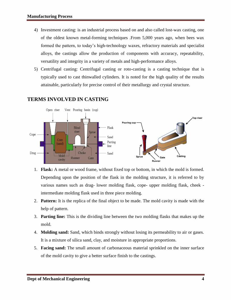
TERMS INVOLVED IN CASTING
1. Flask: A metal or wood frame, without fixed top or bottom, in which the mold is formed.
Depending upon the position of the flask in the molding structure, it is referred to by
various names such as drag- lower molding flask, cope- upper molding flask, cheek -
intermediate molding flask used in three piece molding.
2. Pattern: It is the replica of the final object to be made. The mold cavity is made with the
help of pattern.
3. Parting line: This is the dividing line between the two molding flasks that makes up the
mold.
4. Molding sand: Sand, which binds strongly without losing its permeability to air or gases.
It is a mixture of silica sand, clay, and moisture in appropriate proportions.
5. Facing sand: The small amount of carbonaceous material sprinkled on the inner surface
of the mold cavity to give a better surface finish to the castings.
Manufacturing Process
Dept of Mechanical Engineering 5
6. Core: A separate part of the mold, made of sand and generally baked, which is used to
create openings and various shaped cavities in the castings.
7. Pouring basin: A small funnel shaped cavity at the top of the mold into which the
molten metal is poured.
8. Sprue: The passage through which the molten metal, from the pouring basin, reaches the
mold cavity. In many cases it controls the flow of metal into the mold.
9. Runner: The channel through which the molten metal is carried from the sprue to the
gate.
10. Gate: A channel through which the molten metal enters the mold cavity.
11. Chaplets: Chaplets are used to support the cores inside the mold cavity to take care of its
own weight and overcome the metallo static force.
12. Riser: A column of molten metal placed in the mold to feed the castings as it shrinks and
solidifies. Also known as "feed head".
13. Vent: Small opening in the mold to facilitate escape of air and gases.
STEPS IN MAKING SAND CASTINGS
There are six basic steps in making sand castings:
1. Patternmaking
2. Core making
3. Molding
4. Melting and pouring
5. Cleaning
1. Pattern making: a pattern is a replica of an object to be cast. It is used to prepare a cavity
into which the molten metal is poured. A skilled pattern maker prepares the pattern using wood,
metal, plastic or other materials with the help of machines and special tools. Many factors like
durability, allowance for shrinkage and machining etc are considered while making a pattern.
2. Molding: mould preparation involves forming a cavity by packing sand around a pattern
enclosed in a supporting metallic frame called flask (mould box). When the pattern is removed
from the mould, an exact shaped cavity remains into which the molten metal is poured. Gating
and risering are provided at suitable locations in the mould.
Manufacturing Process
Dept of Mechanical Engineering 6
3. Core making: Cores are forms, usually made of sand, which are placed into a mold cavity to
form the interior surfaces of castings. Thus the void space between the core and mold-cavity
surface is what eventually the casting becomes.
3. 4. Melting and Pouring: metals or alloys of the required composition are melted in a furnace
and then transferred (poured) into the mould cavity. Many factors like temperature of molten
metal, pouring time, turbulence etc, should be considered while melting and pouring.
5. Cleaning and Inspection: after the molten metal has solidified and cooled, the rough casting
is removed from the mould, cleaned and dressed (removing cores, adhered sand particles, gating
and risering systems, fins, blisters etc, from the casting surface) and then sent for inspection to
check for dimensions or any defects like blow holes, cracks, etc.
PROCEDURE FOR MAKING A CASTING:
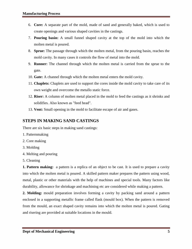
a. Place the pattern in the drag box
b. Ram moulding sand around the pattern and till the top surface of the drag box
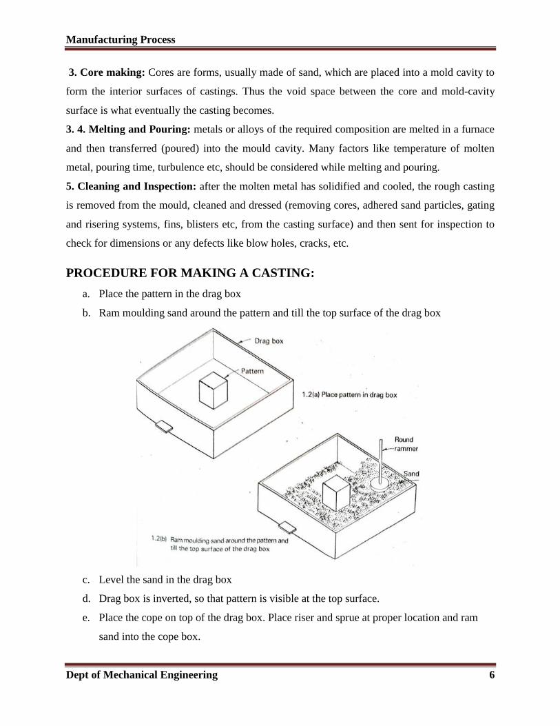
c. Level the sand in the drag box
d. Drag box is inverted, so that pattern is visible at the top surface.
e. Place the cope on top of the drag box. Place riser and sprue at proper location and ram
sand into the cope box.
Manufacturing Process
Dept of Mechanical Engineering 7
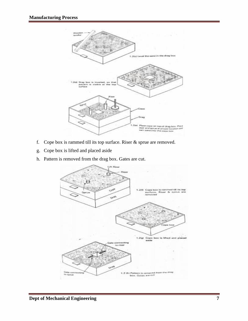
f. Cope box is rammed till its top surface. Riser & sprue are removed.
g. Cope box is lifted and placed aside
h. Pattern is removed from the drag box. Gates are cut.
Manufacturing Process
Dept of Mechanical Engineering 8
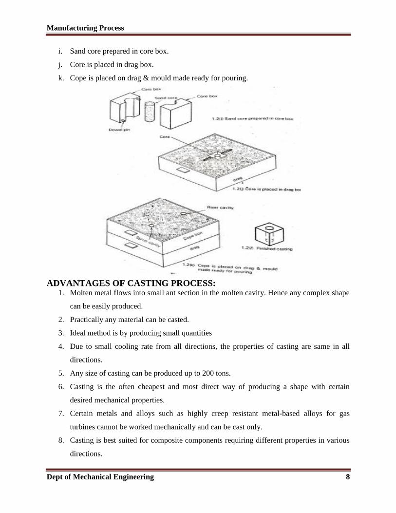
i. Sand core prepared in core box.
j. Core is placed in drag box.
k. Cope is placed on drag & mould made ready for pouring.
ADVANTAGES OF CASTING PROCESS: 1. Molten metal flows into small ant section in the molten cavity. Hence any complex shape
can be easily produced.
2. Practically any material can be casted.
3. Ideal method is by producing small quantities
4. Due to small cooling rate from all directions, the properties of casting are same in all
directions.
5. Any size of casting can be produced up to 200 tons.
6. Casting is the often cheapest and most direct way of producing a shape with certain
desired mechanical properties.
7. Certain metals and alloys such as highly creep resistant metal-based alloys for gas
turbines cannot be worked mechanically and can be cast only.
8. Casting is best suited for composite components requiring different properties in various
directions.
Manufacturing Process
Dept of Mechanical Engineering 9
LIMITATIONS OF CASTING PROCESS:
1. With normal sand casting process, the dimensional accuracies and surface finish is less.
2. Defects are unavoidable.
3. Sand casting is labor intensive.
PATTERN:
Pattern is replica or model of object which to be created. It is used to make hollow cavity
in sand mold in which molten metal is poured and allow solidifying to create object. The size and
shape of cast object is highly depends of shape and size of pattern. Mostly pattern are made by
aluminum, wood, wax etc. Metal pattern are used for mass production. The pattern making is
most critical work in casting because the object is highly depended on it.
A good pattern should follow following requirements.
Low cost and easy to cast.
Easy to repair.
It should light in weight which makes it easy to handle.
It should able to withstand ramming forces without deformation.
It should does not change its dimensions in presence of moisture.
It should be easily removable from mould.
It should have long life without change in its dimensions.
Functions of the Pattern
1. A pattern prepares a mold cavity for the purpose of making a casting.
2. A pattern may contain projections known as core prints if the casting requires a core and
need to be made hollow.
3. Runner, gates, and risers used for feeding molten metal in the mold cavity may form a
part of the pattern.
4. Patterns properly made and having finished and smooth surfaces reduce casting defects.
5. A properly constructed pattern minimizes the overall cost of the castings.
Manufacturing Process
Dept of Mechanical Engineering 10
PATTERN MATERIALS:
Patterns may be constructed from the following materials. Each material has its own
advantages, limitations, and field of application. Some materials used for making patterns are:
wood, metals and alloys, plastic, plaster of Paris, plastic and rubbers, wax, and resins. To be
suitable for use, the pattern material should be:
1. Easily worked, shaped and joined
2. Light in weight
3. Strong, hard and durable
4. Resistant to wear and abrasion.
5. Resistant to corrosion, and to chemical reactions
6. Dimensionally stable and unaffected by variations in temperature and humidity
7. Available at low cost.
TYPES OF PATTERN MATERIALS
1) Wood:
Wood is one kind of material which easily available, cheep, but it absorption moister. As a result
dimension change in the mould cavity.
Ex: Tack wood.
Advantages:
a. Wood is available in plenty compared to other materials
b. Light in weight
c. Comparatively inexpensive
d. Good workability
e. Can be repair
Disadvantages:
a. Poor in strength
b. Affected by moisture of the moulding sand causing swelling and distortion.
c. Less resistant to wear and chemical actions.
d. Not suitable for long production runs.
Manufacturing Process
Dept of Mechanical Engineering 11
2) Metal:
Metal have all preferred properties which above explained. So that casted product surface
finished is better.
Ex: Brass, cobalt, aluminium etc.
Advantages:
a. Metals are strong
b. Wear resistant
c. Dimensionally stable under changing humidity
d. Gives good surface finish to castings
e. Suitable for mass production.
Disadvantages:
a. Metals are heavy
b. Costlier
c. Tendency to rust during long storage periods.
d. Initially they have to be cast or machined to the desired shape and size. This leads to the
increase in cost of the final cast product.
3) Plastics:
This pattern is preferred where wax pattern are not suitable. Plastic materials are a compromise
between wood and metal. Thermosetting resins like phenolic resin, epoxy resin, foam plastic etc
are used as materials for making pattern.
Ex: Polystyrene, PVC, Epoxy-resin etc.
Advantages:
a. Moderately strong and light in weight.
b. Does not absorb moisture during its use and storage.
c. Gives good surface finish to castings.
Disadvantages:
a. Initially plastic patterns have to be cast and finished to desired shape and size. This leads
to increase in cost of the final cast product.
b. Thin sections are difficult to cast using plastics.
Manufacturing Process
Dept of Mechanical Engineering 12
4) Wax:
Wax is a re-usable material. It is light in weight, gives good surface finish and suitable for
complex shapes. Withdrawal of wax pattern from the mould is easier compared to toher pattern
materials. This is done by inverting the mould box and heating it to a suitable temperature. The
wax melts and drops down leaving a fine finished cavity in the mould.
PATTERN ALLOWANCES
Pattern allowance is a vital feature as it affects the dimensional characteristics of the
casting. Thus, when the pattern is produced, certain allowances must be given on the
sizes specified in the finished component drawing so that a casting with the particular
specification can be made. The selection of correct allowances greatly helps to reduce
machining costs and avoid rejections. The allowances usually considered on patterns and
core boxes are as follows:
1. Shrinkage or contraction allowance
2. Draft or taper allowance
3. Machining or finish allowance
4. Distortion or camber allowance
5. Rapping allowance.
1. Shrinkage or Contraction Allowance:
The various metals used for casting contract after solidification in the mould. Since the
contraction is different for different materials, therefore it will also differ with the form or type
of metal. All most all cast metals shrink or contract volumetrically on cooling.
The metal shrinkage is of two types:
i. Liquid Shrinkage: it refers to the reduction in volume when the metal changes from
liquid state to solid state at the solidus temperature. To account for this shrinkage;
riser, which feed the liquid metal to the casting, are provided in the mold.
ii. ii. Solid Shrinkage: it refers to the reduction in volume caused when metal loses
temperature in solid state. To account for this, shrinkage allowance is provided on the
patterns.
Manufacturing Process
Dept of Mechanical Engineering 13
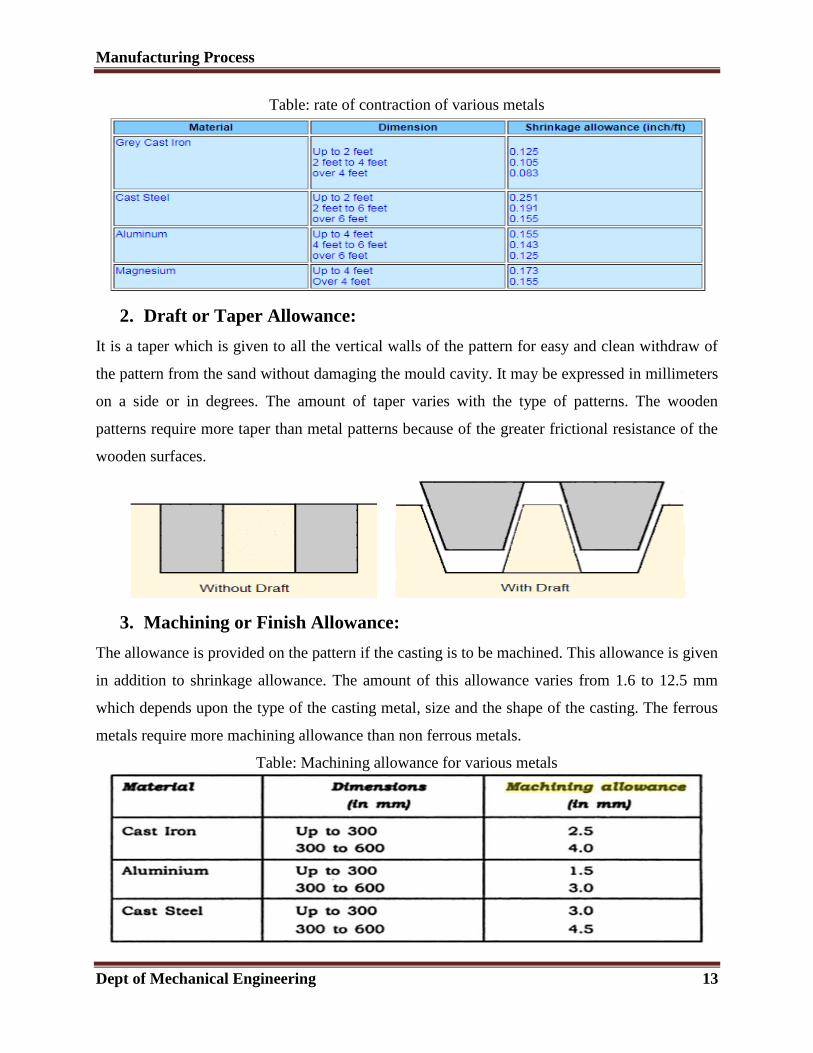
Table: rate of contraction of various metals
2. Draft or Taper Allowance:
It is a taper which is given to all the vertical walls of the pattern for easy and clean withdraw of
the pattern from the sand without damaging the mould cavity. It may be expressed in millimeters
on a side or in degrees. The amount of taper varies with the type of patterns. The wooden
patterns require more taper than metal patterns because of the greater frictional resistance of the
wooden surfaces.
3. Machining or Finish Allowance:
The allowance is provided on the pattern if the casting is to be machined. This allowance is given
in addition to shrinkage allowance. The amount of this allowance varies from 1.6 to 12.5 mm
which depends upon the type of the casting metal, size and the shape of the casting. The ferrous
metals require more machining allowance than non ferrous metals.
Table: Machining allowance for various metals
Manufacturing Process
Dept of Mechanical Engineering 14
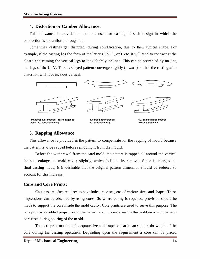
4. Distortion or Camber Allowance:
This allowance is provided on patterns used for casting of such design in which the
contraction is not uniform throughout.
Sometimes castings get distorted, during solidification, due to their typical shape. For
example, if the casting has the form of the letter U, V, T, or L etc. it will tend to contract at the
closed end causing the vertical legs to look slightly inclined. This can be prevented by making
the legs of the U, V, T, or L shaped pattern converge slightly (inward) so that the casting after
distortion will have its sides vertical.
5. Rapping Allowance:
This allowance is provided in the pattern to compensate for the rapping of mould because
the pattern is to be rapped before removing it from the mould.
Before the withdrawal from the sand mold, the pattern is rapped all around the vertical
faces to enlarge the mold cavity slightly, which facilitate its removal. Since it enlarges the
final casting made, it is desirable that the original pattern dimension should be reduced to
account for this increase.
Core and Core Prints:
Castings are often required to have holes, recesses, etc. of various sizes and shapes. These
impressions can be obtained by using cores. So where coring is required, provision should be
made to support the core inside the mold cavity. Core prints are used to serve this purpose. The
core print is an added projection on the pattern and it forms a seat in the mold on which the sand
core rests during pouring of the m old.
The core print must be of adequate size and shape so that it can support the weight of the
core during the casting operation. Depending upon the requirement a core can be placed
Manufacturing Process
Dept of Mechanical Engineering 15
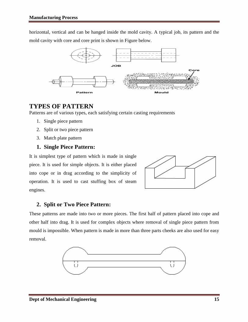
horizontal, vertical and can be hanged inside the mold cavity. A typical job, its pattern and the
mold cavity with core and core print is shown in Figure below.
TYPES OF PATTERN Patterns are of various types, each satisfying certain casting requirements
1. Single piece pattern
2. Split or two piece pattern
3. Match plate pattern
1. Single Piece Pattern:
It is simplest type of pattern which is made in single
piece. It is used for simple objects. It is either placed
into cope or in drag according to the simplicity of
operation. It is used to cast stuffing box of steam
engines.
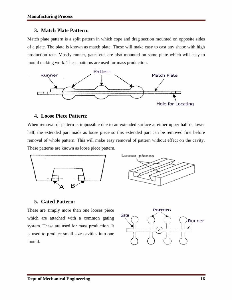
2. Split or Two Piece Pattern:
These patterns are made into two or more pieces. The first half of pattern placed into cope and
other half into drag. It is used for complex objects where removal of single piece pattern from
mould is impossible. When pattern is made in more than three parts cheeks are also used for easy
removal.
Manufacturing Process
Dept of Mechanical Engineering 16
3. Match Plate Pattern:
Match plate pattern is a split pattern in which cope and drag section mounted on opposite sides
of a plate. The plate is known as match plate. These will make easy to cast any shape with high
production rate. Mostly runner, gates etc. are also mounted on same plate which will easy to
mould making work. These patterns are used for mass production.
4. Loose Piece Pattern:
When removal of pattern is impossible due to an extended surface at either upper half or lower
half, the extended part made as loose piece so this extended part can be removed first before
removal of whole pattern. This will make easy removal of pattern without effect on the cavity.
These patterns are known as loose piece pattern.
5. Gated Pattern:
These are simply more than one looses piece
which are attached with a common gating
system. These are used for mass production. It
is used to produce small size cavities into one
mould.
Manufacturing Process
Dept of Mechanical Engineering 17
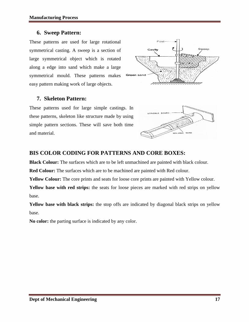
6. Sweep Pattern:
These patterns are used for large rotational
symmetrical casting. A sweep is a section of
large symmetrical object which is rotated
along a edge into sand which make a large
symmetrical mould. These patterns makes
easy pattern making work of large objects.
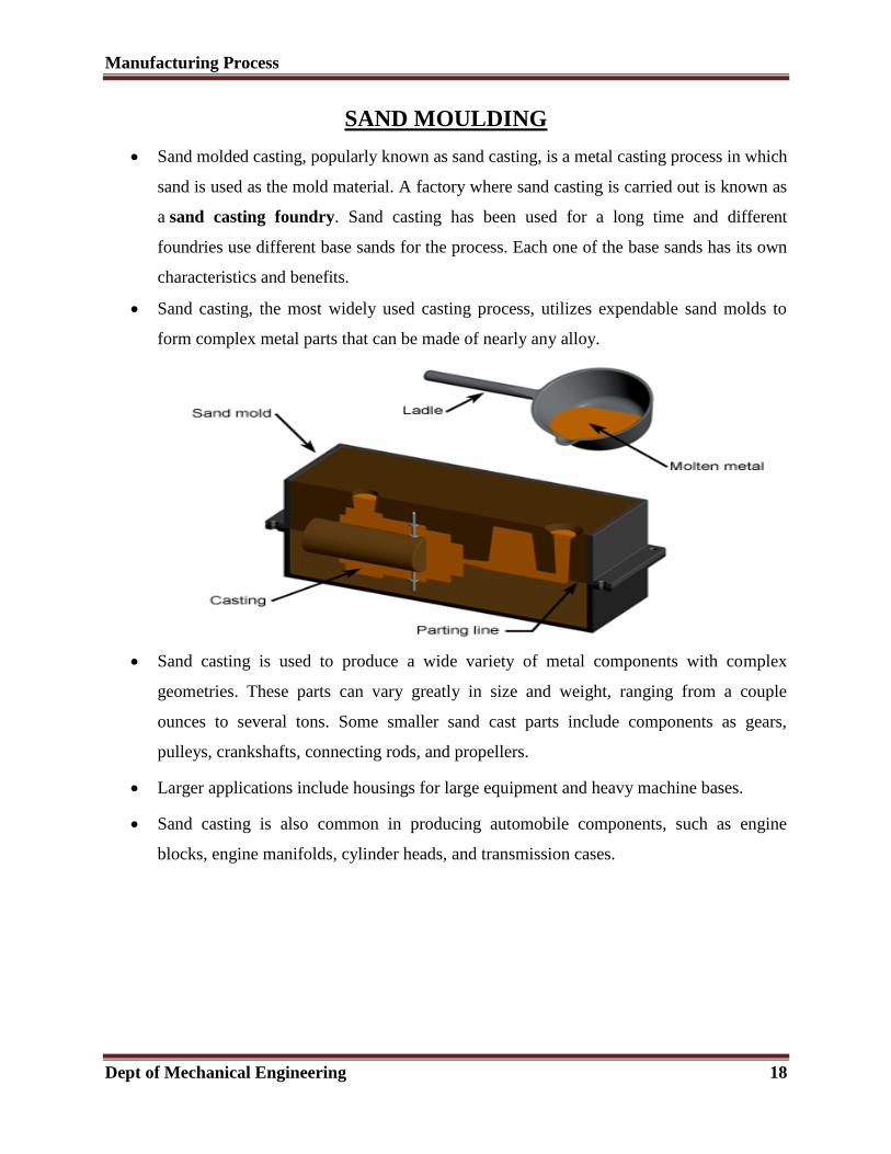
7. Skeleton Pattern:
These patterns used for large simple castings. In
these patterns, skeleton like structure made by using
simple pattern sections. These will save both time
and material.
BIS COLOR CODING FOR PATTERNS AND CORE BOXES:
Black Colour: The surfaces which are to be left unmachined are painted with black colour.
Red Colour: The surfaces which are to be machined are painted with Red colour.
Yellow Colour: The core prints and seats for loose core prints are painted with Yellow colour.
Yellow base with red strips: the seats for loose pieces are marked with red strips on yellow
base.
Yellow base with black strips: the stop offs are indicated by diagonal black strips on yellow
base.
No color: the parting surface is indicated by any color.
Manufacturing Process
Dept of Mechanical Engineering 18
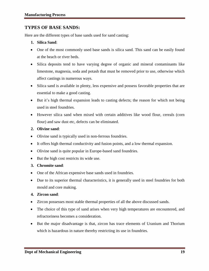
SAND MOULDING
Sand molded casting, popularly known as sand casting, is a metal casting process in which
sand is used as the mold material. A factory where sand casting is carried out is known as
a sand casting foundry. Sand casting has been used for a long time and different
foundries use different base sands for the process. Each one of the base sands has its own
characteristics and benefits.
Sand casting, the most widely used casting process, utilizes expendable sand molds to
form complex metal parts that can be made of nearly any alloy.
Sand casting is used to produce a wide variety of metal components with complex
geometries. These parts can vary greatly in size and weight, ranging from a couple
ounces to several tons. Some smaller sand cast parts include components as gears,
pulleys, crankshafts, connecting rods, and propellers.
Larger applications include housings for large equipment and heavy machine bases.
Sand casting is also common in producing automobile components, such as engine
blocks, engine manifolds, cylinder heads, and transmission cases.
Manufacturing Process
Dept of Mechanical Engineering 19
TYPES OF BASE SANDS:
Here are the different types of base sands used for sand casting:
1. Silica Sand:
One of the most commonly used base sands is silica sand. This sand can be easily found
at the beach or river beds.
Silica deposits tend to have varying degree of organic and mineral contaminants like
limestone, magnesia, soda and potash that must be removed prior to use, otherwise which
affect castings in numerous ways.
Silica sand is available in plenty, less expensive and possess favorable properties that are
essential to make a good casting.
But it’s high thermal expansion leads to casting defects; the reason for which not being
used in steel foundries.
However silica sand when mixed with certain additives like wood flour, cereals (corn
flour) and saw dust etc, defects can be eliminated.
2. Olivine sand:
Olivine sand is typically used in non-ferrous foundries.
It offers high thermal conductivity and fusion points, and a low thermal expansion.
Olivine sand is quite popular in Europe-based sand foundries.
But the high cost restricts its wide use.
3. Chromite sand:
One of the African expensive base sands used in foundries.
Due to its superior thermal characteristics, it is generally used in steel foundries for both
mould and core making.
4. Zircon sand:
Zircon possesses most stable thermal properties of all the above discussed sands.
The choice of this type of sand arises when very high temperatures are encountered, and
refractoriness becomes a consideration.
But the major disadvantage is that, zircon has trace elements of Uranium and Thorium
which is hazardous in nature thereby restricting its use in foundries.
Manufacturing Process
Dept of Mechanical Engineering 20
TYPES OF SAND MOULDS The various types of moulding sand are
1. Green sand
2. Dry sand
3. Loam sand
4. Parting sand
5. Facing sand
6. Backing sand
7. System sand
8. Core sand
1. Green Sand
Green sand is a mixture of silica sand and clay. It constitutes 18 % to 30 % clay and 6 % to 8 %
water.
The water and clay present is responsible for furnishing bonds for the green sand.
It is slightly wet when squeezed with hand. It has the ability to retain the shape and impression
given to it under pressure.
It is easily available and has low cost.
The mould which is prepared in this sand is called green sand mould.
It is commonly used for producing ferrous and non-ferrous castings
2. Dry Sand
After making the mould in green sand, when it is dried or baked is called dry sand.
It is suitable for making large castings.
The moulds which is prepared in dry sand is known as dry sand moulds.
If we talk about the physical composition of the dry sand, than it is same as that of the green sand
except water.
3. Loam Sand
It is a type of moulding sand in which 50 % of clay is present.
It is mixture of sand and clay and water is present in such a quantity, to make it a thin plastic
paste.
In loam moulding patterns are not used.
It is used to produce large casting.
Manufacturing Process
Dept of Mechanical Engineering 21
4. Parting Sand
Parting sand is used to prevent the sticking of green sand to the pattern and also to allow the sand
on the parting surface of the cope and drag to separate without clinging.
It serves the same purpose as of parting dust.
It is clean clay free silica sand.
5. Facing Sand
The face of the mould is formed by facing sand.
Facing sand is used directly next to the surface of the pattern and it comes in direct contact with
the molten metal, when the molten metal is poured into the mould.
It possesses high strength and refractoriness as it comes in contact with the molten metal.
It is made of clay and silica sand without addition of any used sand.
6. Backing Sand
Backing sand or flour sand is used to back up facing sand.
Old and repeatedly used moulding sand is used for the backing purpose.
It is also sometimes called black sand because of the addition of coal dust and burning when it
comes in contact with the molten metal.
7. System Sand
In mechanical sand preparation and handling units, facing sand is not used. The sand which is
used is cleaned and reactivated by adding of water, binder and special additives. And the sand we
get through this is called system sand.
System sand is used to fill the whole flask in the mechanical foundries where machine moulding
is employed.
The mould made with this sand has high strength, permeability and refractoriness.
8. Core Sand
The sand which is used to make core is called core sand.
It is also called as oil sand.
It is a mixture of silica sand and core oil. Core oil is mixture of linseed oil, resin, light mineral oil
and other binding materials.
For the sake of economy, pitch or flours and water may be used in making of large cores.
Manufacturing Process
Dept of Mechanical Engineering 22
REQUIREMENTS/PROPERTIES OF MOULDING SAND:
The moulding is a process of making a cavity or mould out of sand by means of a pattern. The
molten metal is poured into the moulds to produce casting.
1. Porosity or permeability: It is the property of sand which permits the steam and other gases
to pass through the sand mould. The porosity of sand depends upon its grain size, grain shape,
moisture and clay components are the moulding sand. If the sand is too fine, the porosity will be
low.
2. Hot strength: As soon as the moisture is eliminated, the sand would reach at a high
temperature when the metal in the mold is still in liquid state. The strength of the sand that is
required to hold the shape of the cavity is called hot strength.
3. Plasticity: It is that property of sand due to which it flows to all portions of the moulding box
or flask. The sand must have sufficient plasticity to produce a good mould.
4. Adhesiveness: It is that properties of sand due to it adheres or cling to the sides of the
moulding box.
5. Cohesiveness: It is the property of sand due to which the sand grains stick together during
ramming. It is defined as the strength of the moulding sand.
6. Refractoriness: The property which enables it to resist high temperature of the molten metal
without breaking down or fusing.
7. Flowability: The property of the molding sand to flow and fill the narrow portions
surrounding the pattern and the sand should have good flowability.
8. Surface finish: It should have the ability to produce good surface finish in the casting.
METHODS OF MOULDING:
In general moulding methods can be classified in following six categories:
1. Floor Moulding
2. Bench Moulding
3. Pit Moulding
4. Machine Moulding.
1. Floor Molding: This type of molding is preferred for medium and large size jobs. In this
method, only drag portion of molding flask is used to make the mold and the floor itself is
utilized as drag and it is usually performed with dry sand.
Manufacturing Process
Dept of Mechanical Engineering 23
2. Bench Molding: This type of molding is preferred for small jobs. The whole molding
operation is carried out on a bench of convenient height. In this process, a minimum of two
flasks, namely cope and drag molding flasks are necessary. But in certain cases, the number of
flasks may increase depending upon the number of parting surfaces required.
3. Pit Molding:
In this method, the moulding is carried out in the pits and generally, very large moulds are made,
the pit serving the purpose of flask. Generally, green sand is used in pit moulding but cement
bonded sand sections may also be used. For large moulds, this is the only method of moulding
and is quite slow and laborious.
4. Machine Moulding: The moulding is done by using a moulding machine, is called machine
moulding. A moulding machine performs number of operations which does by moulder hands.
The function of these machines is to pack the sand onto the pattern and draw the pattern out from
the mould.
Some other operations performed by machine are ; ramming of sand, compressing the sand,
forming the gate, forming the runner, drawing out the pattern without enlarging the mould
cavity, etc. Machine moulding increases the production rate and productivity.
CLASSIFICATION BASED ON THE MOULD MATERIAL:
SAND MOLDING
Molding processes where a sand aggregate is used to make the mold produce by far the largest
quantity of castings. Whatever the metal poured into sand molds, the product may be called a
sand casting.
(a) GREEN-SAND MOLDING: Among the sand-casting processes, molding is most often
done with green sand. Green molding sand may be defined as a plastic mixture of sand grains,
clay, water, and other materials which can be used for molding and casting processes. The sand
is called "green" because of the moisture present and is thus distinguished from dry sand.
Advantages are:
1. Great flexibility as a production process. Mechanical equipment can be utilized for
performing molding and its allied operations. Furthermore, green sand can be reused
many times by reconditioning it with water, clay, and ether materials. The molding
process can be rapid and repetitive.
Manufacturing Process
Dept of Mechanical Engineering 24
2. Usually, the meat direct route from pattern to mold ready for pouring is by green –sand
molding.
3. Economy, green sand molding is ordinarily the least costly method of molding.
Limitations in the use of green-sand molding are:
1. Some casting designs require the use of other casting processes. Thin, long projections of
green sand in a mold cavity are washed away by the molten metal or may not even be
moldable. Cooling fins on air-cooled-engine cylinder blocks and head are an example.
Greater strength is then required of the mold.
2. Certain metals and some castings develop defects if poured into molds containing
moisture.
3. The dimensional accuracy and surface finish of green-sand castings may not be adequate.
4. Large castings require greater mold strength and resistance to erosion than are available
in green sands.
(b) DRY-SAND MOULDS:
Dry-sand molds are actually made with molding sand in the green condition.
The sand mixture is modified somewhat to favor good strength and other properties after
the mold is dried.
Dry-sand molding may be done the same way as green-sand molding on smaller sizes of
castings.
Usually, the mold-cavity surface is coated or sprayed with a mixture which, upon drying,
imparts
Greater hardness or refractoriness to the mold. The entire mold is then dried in an oven at
300 to
650 F or by circulating heated air through the mold. The time-consuming drying
operation is one
Inherent disadvantage of the dry-sand mold.
Advantages
1. Dry sand molds are generally stronger than green sand molds and therefore can withstand
much additional handling.
2. Better dimension control than if they were molded in green sand.
Manufacturing Process
Dept of Mechanical Engineering 25
3. The improved quality of the sand mixture due to the removal of moisture can result in a
much smoother finish on the castings than if made in green sand molds. Where molds are
properly washed and sprayed with refractory coatings, the casting finish is further
improved.
Disadvantages
This type of molding is much more expensive than green sand molding and is not a high
production process. Correct baking (drying) times are essential.
(c) SKIN-DRIED MOULDS:
The effect of a dry-sand mold may be partially obtained by drying the mold surface to some
depth, 1/4 to 1 in. Skin drying may be performed by torches or electrical heating elements
directed at the mold surface. Skin-dried molds must be poured shortly after drying, so that
moisture from the undried sand will not penetrate the dried skin.
BINDERS:
1. Binders are added to give cohesion to molding sands.
2. Binders provide strength to the molding sand and enable it to retain its shape as mold
cavity.
3. Binders should be added in optimum quantity as they reduce refractoriness and
permeability.
4. An optimal quantity of binders is needed, as further increases have no effect on properties
of foundry sand.
The following binders are generally added to foundry sand:
i. Fireclay: It is usually found near coal mines. For use in the foundry, the hard black
lumps of fireclay are taken out, weathered and pulverized. Since the size of fireclay
particles is nearly 400 times greater than the size of bentonite particles, they give poor
bonding strength to foundry sand.
ii. Bentonite: It is the most suitable material used in molding sands.
iii. Limonite and Kaolinite are not commonly used as binders as they have comparatively
low binding properties.
Manufacturing Process
Dept of Mechanical Engineering 26
iv. Illite: Illite is found in natural molding sands that are formed by the decomposition of
micaceous materials due to weathering. Illite possesses moderate shrinkage and poor
bonding strength than bentonite.
ADDITIVES
Additives are the materials generally added to the molding and core sand mixture to develop
some special property in the sand. Some common used additives for enhancing the properties of
molding and core sands are.
(i) Coal dust
Coal dust is added mainly for producing a reducing atmosphere during casting. This reducing
atmosphere results in any oxygen in the poles becoming chemically bound so that it cannot
oxidize the metal.
(ii) Dextrin
Dextrin belongs to starch family of carbohydrates. It increases dry strength of the molds.
(iii) Pitch
It is distilled form of soft coal. It can be added from 0.02 % to 2% in mold and core sand. It
enhances hot strengths, surface finish on mold surfaces.
(iv) Wood flour
This is a fibrous material mixed with a granular material like sand; its relatively long thin fibers
prevent the sand grains from making contact with one another. It can be added from 0.05 % to
2% in mold and core sand. It increases collapsibility of both of mold and core.


