
ZX-T Series
Cat. No. I159E-EN-01
R6Y - XGC/XGP series
MAINTENANCE MANUAL
SCARA RobotsXG Series


CONTENTS XGC/XGPMaintenance Manual
T-1
Safety Instructions
1. Safety Information S-1
2. Signal words used in this manual S-2
3. Warning labels S-3
3.1 Warning labels S-33.1.1 Warning label messages on robot and controller S-3
3.1.2 Supplied warning labels S-6
3.2 Warning symbols S-7
4. Major precautions for each stage of use S-8
4.1 Precautions for using robots and controllers S-8
4.2 Design S-94.2.1 Precautions for robots S-9
4.2.2 Precautions for robot controllers S-9
4.3 Moving and installation S-104.3.1 Precautions for robots S-10
4.3.2 Precautions for robot controllers S-11
4.4 Safety measures S-134.4.1 Safety measures S-13
4.4.2 Installing a safety enclosure S-14
4.5 Operation S-154.5.1 Trial operation S-15
4.5.2 Automatic operation S-17
4.5.3 Precautions during operation S-17
4.6 Inspection and maintenance S-194.6.1 Before inspection and maintenance work S-19
4.6.2 Precautions during service work S-20
4.7 Disposal S-21
5. Emergency action when a person is caught by robot S-22
6. Cautionsregardingstrongmagneticfields S-22
7. Using the robot safely S-23
7.1 Movement range S-23
7.2 Robot protective functions S-24
7.3 Residual risk S-25
7.4 Special training for industrial robot operation S-25
Warranty

CONTENTS XGC/XGPMaintenance Manual
T-2
Chapter 1 Overview
1. Overview 1-1
Chapter 2 Attaching, detaching, and replacing the cover
1. Attaching, detaching, and replacing the cover 2-1
1.1 R6YXGLC(P)250, R6YXGLC(P)350, R6YXGLC(P)400, R6YXGLC(P)500, R6YXGLC(P)600 2-1
1.2 R6YXGP500, R6YXGP600, R6YXGHP600, R6YXGP700, R6YXGP800, R6YXGP900, R6YXGP1000 2-6
Chapter 3 Periodic inspection
1. Periodic inspection 3-1
1.1 Six-month inspection 3-1
2. Applying the grease 3-3
2.1 Applying the grease to the spline shaft 3-3
2.2 Applying the grease to the ball screw 3-4
Chapter 4 Robot settings
1. Overview 4-1
2. Adjusting the origin 4-2
3. Standard coordinate setting using a standard coordinate setup jig 4-3
3.1 R6YXGLC(P)250, R6YXGLC(P)350, R6YXGLC(P)400, R6YXGLC(P)500, R6YXGLC(P)600 4-3
3.2 R6YXGP500, R6YXGP600, R6YXGHP600, R6YXGP700, R6YXGP800, R6YXGP900, R6YXGP1000 4-4
Chapter 5 Replacing the harmonic drive
1. Cautions on replacement of the harmonic drive 5-1
2. Replacement procedure for harmonic drive 5-2
2.1 R6YXGLC(P)250, R6YXGLC(P)350, R6YXGLC(P)400, R6YXGLC(P)500, R6YXGLC(P)600 5-32.1.1 Replacing the X-axis harmonic drive 5-3
2.1.2 Replacing the Y-axis harmonic drive 5-12
2.1.3 Replacing the R-axis harmonic drive 5-18
2.2 R6YXGP500, R6YXGP600, R6YXGHP600, R6YXGP700, R6YXGP800, R6YXGP900, R6YXGP1000 5-292.2.1 Replacing the X-axis harmonic drive 5-29
2.2.2 Replacing the Y-axis harmonic drive 5-38
2.2.3 Replacing the R-axis harmonic drive 5-49

CONTENTS XGC/XGPMaintenance Manual
T-3
Chapter 6 Replacing the machine harness
1. Replacing the machine harness 6-1
1.1 R6YXGLC(P)250, R6YXGLC(P)350, R6YXGLC(P)400, R6YXGLC(P)500, R6YXGLC(P)600 6-1
1.2 R6YXGP500, R6YXGP600, R6YXGHP600, R6YXGP700, R6YXGP800, R6YXGP900, R6YXGP1000 6-7
2. Y-axis arm side I/O connector replacement 6-16
3. Base side I/O connector replacement 6-17
Chapter 7 Replacing the bellows
1. Replacing the upper bellows 7-1
2. Replacing the lower bellows 7-3
Chapter 8 Replacing the Z-axis ASSY
1. Replacing the Z-axis ASSY 8-1
1.1 R6YXGLC(P)250, R6YXGLC(P)350, R6YXGLC(P)400, R6YXGLC(P)500, R6YXGLC(P)600 8-1
1.2 R6YXGP500, R6YXGP600, R6YXGHP600, R6YXGP700, R6YXGP800, R6YXGP900, R6YXGP1000 8-5
Chapter 9 Replacing the spline
1. Replacing the spline 9-1
1.1 R6YXGLC(P)250, R6YXGLC(P)350, R6YXGLC(P)400, R6YXGLC(P)500, R6YXGLC(P)600 9-1
1.2 R6YXGP500, R6YXGP600, R6YXGHP600, R6YXGP700, R6YXGP800, R6YXGP900, R6YXGP1000 9-3
Chapter 10 Motor replacement
1. Motor replacement 10-1
1.1 X and R axis motor replacement 10-1
1.2 Y-axis motor replacement 10-1
1.3 Z-axis motor replacement 10-3
Chapter 11 Sensor replacement
1. Sensor replacement 11-1
1.1 X, Y-axis sensor replacement 11-1
1.2 R-axis sensor replacement 11-4
Chapter 12 Robot cable replacement
1. Robot cable replacement 12-1

CONTENTS XGC/XGPMaintenance Manual
T-4
Chapter 13 Mechanical stopper replacement
1. Mechanical stopper replacement 13-1
1.1 X, Y-axis mechanical stoppers 13-1
1.2 Z-axis mechanical stopper 13-31.2.1 Upper end mechanical stopper 13-3
1.2.2 Lower end mechanical stopper 13-3
Chapter 14 Dog replacement
1. Dog replacement 14-1
Chapter 15 Bellows rotation mechanism replacement
1. Lower bellows rotation mechanism replacement 15-1
2. Upper bellows rotation mechanism replacement 15-4
Chapter 16 End face seal replacement
1. End face seal replacement 16-1
1.1 ReplacingtheX-axisendfaceseal(onlyondust/dripproofspecificationmodelsXG(L)P) 16-1
1.2 ReplacingtheY-axisendfaceseal(onlyondust/dripproofspecificationmodelsXG(L)P) 16-2
1.3 Replacing the R-axis end face seal 16-3
Chapter 17 Maintenance parts
1. Maintenance parts 17-1
1.1 Standard type 17-1
1.2 Toolflangemounttype 17-4
2. Consumable parts 17-7
3. Basicspecification 17-8

Contents
1. Safety Information S-1
2. Signal words used in this manual S-2
3. Warning labels S-33.1 Warning labels S-3
3.1.1 Warning label messages on robot and controller S-33.1.2 Supplied warning labels S-6
3.2 Warning symbols S-7
4. Major precautions for each stage of use S-84.1 Precautions for using robots and controllers S-8
4.2 Design S-9
4.2.1 Precautions for robots S-94.2.2 Precautions for robot controllers S-9
4.3 Moving and installation S-10
4.3.1 Precautions for robots S-104.3.2 Precautions for robot controllers S-11
4.4 Safety measures S-13
4.4.1 Safety measures S-134.4.2 Installing a safety enclosure S-14
4.5 Operation S-15
4.5.1 Trial operation S-154.5.2 Automatic operation S-174.5.3 Precautions during operation S-17
4.6 Inspection and maintenance S-19
4.6.1 Before inspection and maintenance work S-194.6.2 Precautions during service work S-20
4.7 Disposal S-21
5. Emergency action when a person is caught by robot S-22
6. Cautions regarding strong magnetic fields S-22
7. Using the robot safely S-237.1 Movement range S-23
7.2 Robot protective functions S-24
7.3 Residual risk S-25
7.4 Special training for industrial robot operation S-25
Safety Instructions


Sa
fety Instruc
tions
S-1
1. Safety InformationIndustrial robots are highly programmable, mechanical devices that provide a large degree of freedom when performing various manipulative tasks. To ensure safe and correct use of OMRON industrial robots and controllers, carefully read and comply with the safety instructions and precautions in this "Safety Instructions" guide. Failure to take necessary safety measures or incorrect handling may result in trouble or damage to the robot and controller, and also may cause personal injury (to installation personnel, robot operator or service personnel) including fatal accidents.
Before using this product, read this manual and related manuals and take safety precautions to ensure correct handling. The precautions listed in this manual relate to this product. To ensure safety of the user’s final system that includes OMRON robots, please take appropriate safety measures as required by the user’s individual system.
To use OMRON robots and controllers safely and correctly, always comply with the safety rules and instructions:
• Forspecificsafetyinformationandstandards,refertotheapplicablelocalregulationsandcomplywiththe instructions.
• WarninglabelsattachedtotherobotsarewritteninEnglish,Japanese,ChineseandKorean.Thismanualisavailable inEnglishorJapanese(orsomepartsinChinese).Unlesstherobotoperatorsorservicepersonnelunderstand these languages, do not permit them to handle the robot.
• CautionsregardingtheofficiallanguageofEUcountries: ForequipmentthatwillbeinstalledinEUcountries,thelanguageusedforthemanuals,warninglabels, operationscreencharacters,andCEdeclarationsisEnglishonly. WarninglabelsonlyhavepictogramsorelseincludewarningmessagesinEnglish.Inthelattercase,messages inJapaneseorotherlanguagesmightbeadded.
It is not possible to list all safety items in detail within the limited space of this manual. So please note that it is essential that the user have a full knowledge of safety and also make correct judgments on safety procedures.

Sa
fety Instruc
tions
S-2
2. Signal words used in this manualThis manual uses the following safety alert symbols and signal words to provide safety instructions that must be observed and to describe handling precautions, prohibited actions, and compulsory actions. Make sure you understand the meaning of each symbol and signal word and then read this manual.
DANGER ThIsIndICaTEsanImmEdIaTELYhazaRdoUssITUaTIonWhICh,IFnoTavoIdEd,WILLREsULTIndEaThoRsERIoUsInJURY.
WARNING ThIsIndICaTEsaPoTEnTIaLLYhazaRdoUssITUaTIonWhICh,IFnoTavoIdEd,CoULdREsULTIndEaThoRsERIoUsInJURY.
CAUTION This indicates a potentially hazardous situation which, if not avoided, could result in minor or moderate injury, or damage to the equipment.
NOTE Explainsthekeypointintheoperationinasimpleandclearmanner.

Sa
fety Instruc
tions
S-3
3. Warning labelsWarning labels shown below are attached to the robot body and controller to alert the operator to potential hazards. To ensure correct use, read the warning labels and comply with the instructions.
3.1 Warning labels
WARNING IFWaRnInGLabELsaREREmovEdoRdIFFICULTTosEE,ThEnThEnECEssaRYPRECaUTIonsmaYnoTbETaKEn,REsULTInGInanaCIdEnT. • donoTREmovE,aLTERoRsTaInThEWaRnInGLabELsonThERoboTbodY. • donoTaLLoWWaRnInGLabELsTobEhIddEnbYdEvICEsInsTaLLEdonThERoboTbYThEUsER. • PRovIdEPRoPERLIGhTInGsoThaTThEsYmboLsandInsTRUCTIonsonThEWaRnInGLabELsCanbE CLEaRLYsEEnFRomoUTsIdEThEsaFETYEnCLosURE.
3.1.1 Warning label messages on robot and controllerWord messages on the danger, warning and caution labels are concise and brief instructions. For more specific instructions, read and follow the "Instructions on this label" described on the right of each label shown below. See “7.1 Movement range” in “Safety instructions” for details on the robot’s movement range.
1. Warning label 1 (SCARA robots)
DANGER sERIoUsInJURYmaYREsULTFRomConTaCTWIThamovInGRoboT. • KEEPoUTsIdEoFThERoboTsaFETYEnCLosUREdURInGoPERaTIon. • PREssThEEmERGEnCYsToPbUTTonbEFoREEnTERInGThEsaFETYEnCLosURE.
Instructions on this label
• alwaysinstallasafetyenclosuretokeepallpersonsawayfrom the robot movement range and prevent injury from contacting the moving part of the robot.
• Install an interlock that triggers emergency stop when the door or gate of the safety enclosure is opened.
• Thesafetyenclosureshouldbedesignedsothatnoonecan enter inside except from the door or gate equipped with an interlock device.
• Warninglabel1thatcomessuppliedwitharobotshouldbe affixed to an easy-to-see location on the door or gate of the safety enclosure.
Potential hazard to human body Serious injury may result from contact with a moving robot.
To avoid hazard•Keepoutsideoftherobotsafetyenclosureduringoperation. •Presstheemergencystopbuttonbeforeenteringthesafetyenclosure.
2. Warning label 2 (SCARA robots)
WARNING movInGPaRTsCanPInChoRCRUshhands. KEEPhandsaWaYFRomThEmovabLEPaRTsoFThERoboT.
Instructions on this label
Use caution to prevent hands and fingers from being pinched or crushed by the movable parts of the robot when transporting or moving the robot or during teaching.
Potential hazard to human body Moving parts can pinch or crush hands.
To avoid hazard Keephandsawayfromthemovablepartsoftherobot.

Sa
fety Instruc
tions
S-4
3. Warning label 3 (SCARA robots)
WARNING ImPRoPERInsTaLLaTIonoRoPERaTIonmaYCaUsEsERIoUsInJURY. bEFoREInsTaLLInGoRoPERaTInGThERoboT,REadThEmanUaLandInsTRUCTIonsonThEWaRnInGLabELsandUndERsTandThEConTEnTs.
Instructions on this label
• besuretoreadthewarninglabelandthismanualcarefully to make you completely understand the contents before attempting installation and operation of the robot.
• beforestartingtherobotoperation,evenafteryouhaveread through this manual, read again the corresponding procedures and "Safety instructions" in this manual.
• neverinstall,adjust,inspectorservicetherobotinanymanner that does not comply with the instructions in this manual.
Potential hazard to human body Improper installation or operation may cause serious injury.
To avoid hazardBefore installing or operating the robot, read the manual and instructions on the warning labels and understand the contents.
4. Warning label 4 (SCARA robots)
CAUTION Do not remove the parts on which Warning label 4 is attached. Doing so may damage the ball screw.
Instructions on this label
The Z-axis ball screw will be damaged if the upper end mechanical stopper on the Z-axis spline is removed or moved. Never attempt to remove or move it.
5. Warning label 5 (Controller)
WARNING GRoUndThEConTRoLLERToPREvEnTELECTRICaLshoCK. GRoUndTERmInaLIsLoCaTEdInsIdEThIsCovER. REadThEmanUaLFoRdETaILs.
Instructions on this label
• highvoltagesectioninside
• Topreventelectricalshock,alwaysgroundtherobotusingthe ground terminal located inside the cover.
Potential hazard to human body Electricalshock
To avoid hazard Ground the controller.
Sa
fety Instruc
tions
S-5
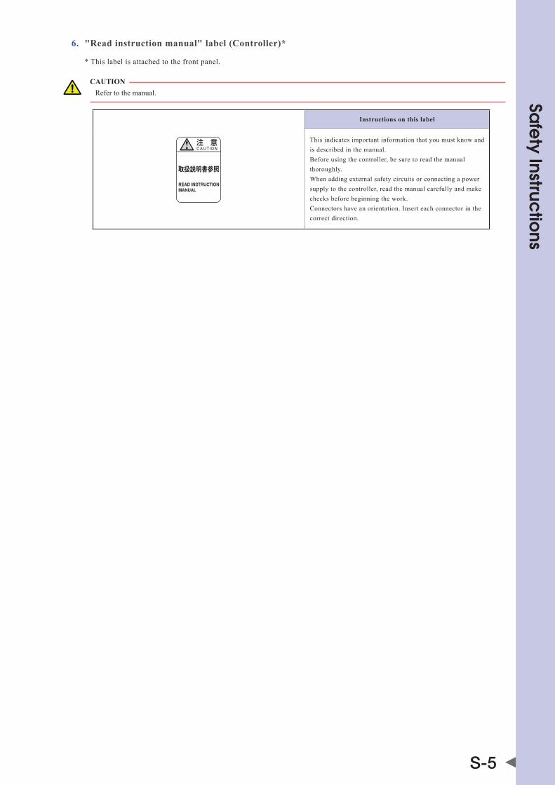
6. "Read instruction manual" label (Controller)*
* This label is attached to the front panel.
CAUTION Refer to the manual.
取扱説明書参照
READ INSTRUCTIONMANUAL
Instructions on this label
This indicates important information that you must know and is described in the manual. Before using the controller, be sure to read the manual thoroughly. When adding external safety circuits or connecting a power supply to the controller, read the manual carefully and make checks before beginning the work. Connectors have an orientation. Insert each connector in the correct direction.

Sa
fety Instruc
tions
S-6
3.1.2 Supplied warning labelsSome warning labels are not affixed to robots but included in the packing box. These warning labels should be affixed to an easy-to-see location.
Warning label is attached to the robot body. Warning label comes supplied with the robot and should be affixed to an easy-to-see location on the door or gate of the safety enclosure.
Warning label comes supplied with the robot and should be affixed to an easy-to-see location.
SCARA robots
Warning label 1
*1
Warning label 2 *1
Warning label 3 *1
*1: See "Part names" in each SCARA robot manual for label positions.

Sa
fety Instruc
tions
S-7
3.2 Warning symbols
Warning symbols shown below are indicated on the robots and controllers to alert the operator to potential hazards. To use the OMRON robot safely and correctly always follow the instructions and cautions indicated by the symbols.
1. Electrical shock hazard symbol
WARNING ToUChInGThETERmInaLbLoCKoRConnECToRmaYCaUsEELECTRICaLshoCK,soUsECaUTIon.
Instructions by this symbol
This indicates a high voltage is present. Touching the terminal block or connector may cause electrical shock.
2. High temperature hazard symbol
WARNING moToRs,hEaTsInKs,andREGEnERaTIvEUnITsbEComEhoT,sodonoTToUChThEm.
Instructions by this symbol
This indicates the area around this symbol may become very hot. Motors, heatsinks, and regenerative units become hot during and shortly after operation. To avoid burns be careful not to touch those sections.
3. Caution symbol
CAUTION Always read the manual carefully before using the controller.
!
Instructions by this symbol
This indicates important information that you must know and is described in the manual. Before using the controller, be sure to read the manual thoroughly. When adding external safety circuits or connecting a power supply to the controller, read the manual carefully and make checks before beginning the work. Connectors must be attached while facing a certain direction, so insert each connector in the correct direction.

Sa
fety Instruc
tions
S-8
4. Major precautions for each stage of useThis section describes major precautions that must be observed when using robots and controllers. Be sure to carefully read and comply with all of these precautions even if there is no alert symbol shown.
4.1 Precautions for using robots and controllers
General precautions for using robots and controllers are described below.
1. Applications where robots cannot be used
OMRON robots and robot controllers are designed as general-purpose industrial equipment and cannot be used for the following applications.
DANGER omRonRoboTConTRoLLERsandRoboTsaREdEsIGnEdasGEnERaL-PURPosEIndUsTRIaLEqUIPmEnTandCannoTbEUsEdFoRThEFoLLoWInGaPPLICaTIons. • InmEdICaLEqUIPmEnTsYsTEmsWhIChaRECRITICaLTohUmanLIFE • InsYsTEmsThaTsIGnIFICanTLYaFFECTsoCIETYandThEGEnERaLPUbLIC • InEqUIPmEnTInTEndEdToCaRRYoRTRansPoRTPEoPLE • InEnvIRonmEnTsWhIChaREsUbJECTTovIbRaTIonsUChasonboaRdshIPsandvEhICLEs.
2. Qualification of operators/workers
Operators or persons who handle the robot such as for teaching, programming, movement check, inspection, adjustment, and repair must receive appropriate training and also have the skills needed to perform the job correctly and safely. They must read the manual carefully to understand its contents before attempting the robot operation or maintenance.
Tasks related to industrial robots (teaching, programming, movement check, inspection, adjustment, repair, etc.) must be performed by qualified persons who meet requirements established by local regulations and standards for industrial robots.
WARNING • ThERoboTmUsTbEoPERaTEdonLYbYPERsonsWhohavERECEIvEdsaFETYandoPERaTIonTRaInInG. oPERaTIonbYanUnTRaInEdPERsonIsEXTREmELYhazaRdoUs. • adJUsTmEnTandmaInTEnanCEbYREmovInGaCovERREqUIREsPECIaLIzEdTEChnICaLKnoWLEdGE andsKILLs,andmaYaLsoInvoLvEhazaRdsIFaTTEmPTEdbYanUnsKILLEdPERson.ThEsETasKs mUsTbEPERFoRmEdonLYbYPERsonsWhohavEEnoUGhabILITYandqUaLIFICaTIonsInaCCoRdanCE WIThLoCaLLaWsandREGULaTIons.FoRdETaILEdInFoRmaTIon,PLEasEConTaCTYoURdIsTRIbUToR WhEREYoUPURChasEdThEPRodUCT.

Sa
fety Instruc
tions
S-9
4.2 Design
4.2.1 Precautions for robots
1. Restricting the robot moving speed
WARNING REsTRICTIononThERoboTmovInGsPEEdIsnoTasaFETY-RELaTEdFUnCTIon. ToREdUCEThERIsKoFCoLLIsIonbETWEEnThERoboTandWoRKERs,ThEUsERmUsTTaKEThEnECEssaRYPRoTECTIvEmEasUREssUChasEnabLEdEvICEsaCCoRdInGToRIsKassEssmEnTbYThEUsER.
2. Restricting the movement range
See “7.1 Movement range” in “Safety instructions” for details on the robot’s movement range.
WARNING soFTLImITFUnCTIonIsnoTasaFETY-RELaTEdFUnCTIonInTEndEdToPRoTECTThEhUmanbodY. ToREsTRICTThERoboTmovEmEnTRanGEToPRoTECTThEhUmanbodY,UsEThEmEChanICaLsToPPERsInsTaLLEdInThERoboT(oRavaILabLEasoPTIons).
CAUTION If the robot moving at high speed collides with a mechanical stopper installed in the robot (or available as option), the robot may be damaged.
3. Provide safety measures for end effector (gripper, etc.)
WARNING • EndEFFECToRsmUsTbEdEsIGnEdandmanUFaCTUREdsoThaTThEYCaUsEnohazaRds(sUChasa LoosEWoRKPIECEoRLoad)EvEnIFPoWER(ELECTRICITY,aIRPREssURE,ETC.)IsshUToFFoRPoWER FLUCTUATIONS OCCUR. • IFThEobJECTGRIPPEdbYThEEndEFFECToRmIGhTPossIbLYFLYoFFoRdRoP,ThEnPRovIdE aPPRoPRIaTEsaFETYPRoTECTIonTaKInGInToaCCoUnTThEobJECTsIzE,WEIGhT,TEmPERaTURE,and ChEmICaLPRoPERTIEs.
4. Provide adequate lighting
Provide enough lighting to ensure safety during work.
5. Install an operation status light
WARNING InsTaLLasIGnaLLIGhT(sIGnaLToWER)aTanEasY-To-sEEPosITIonsoThaTThEoPERaToRWILLbEaWaREoFThERoboTsToPsTaTUs(TEmPoRaRILYsToPPEd,EmERGEnCYsToP,ERRoRsToP,ETC.).
4.2.2 Precautions for robot controllers
1. Emergency stop input terminal
DANGER EaChRoboTConTRoLLERhasanEmERGEnCYsToPInPUTTERmInaLToTRIGGEREmERGEnCYsToP.UsInGThIsTERmInaL,InsTaLLasaFETYCIRCUITsoThaTThEsYsTEmInCLUdInGThERoboTConTRoLLERWILLWoRKsaFELY.
2. Maintain clearance
CAUTION Do not bundle control lines or communication cables together or in close to the main power supply or power lines. Usually separate these by at least 100mm. Failure to follow this instruction may cause malfunction due to noise.

Sa
fety Instruc
tions
S-10
4.3 Moving and installation
4.3.1 Precautions for robots
■ Installation environment
1. Do not use in strong magnetic fields
WARNING donoTUsEThERoboTnEaREqUIPmEnToRInLoCaTIonsThaTGEnERaTEsTRonGmaGnETICFIELds.ThERoboTmaYbREaKdoWnoRmaLFUnCTIonIFUsEdInsUChLoCaTIons.
2. Do not use in locations subject to possible electromagnetic interference, etc.
WARNING donoTUsEThERoboTInLoCaTIonssUbJECTToELECTRomaGnETICInTERFEREnCE,ELECTRosTaTICdIsChaRGEoRRadIoFREqUEnCYInTERFEREnCE.ThERoboTmaYmaLFUnCTIonIFUsEdInsUChLoCaTIonsCREaTInGhazaRdoUssITUaTIons.
3. Do not use in locations exposed to flammable gases
WARNING • omRonRoboTsaREnoTdEsIGnEdTobEEXPLosIon-PRooF. • donoTUsEThERoboTsInLoCaTIonsEXPosEdToEXPLosIvEoRInFLammabLEGasEs,dUsTPaRTICLEs oRLIqUId.FaILUREToFoLLoWThIsInsTRUCTIonmaYCaUsEsERIoUsaCCIdEnTsInvoLvInGInJURYoR dEaTh,oRLEadToFIRE.
■ Moving
1. Use caution to prevent pinching or crushing of hands or fingers
WARNING movInGPaRTsCanPInChoRCRUshhandsoRFInGERs. KEEPhandsaWaYFRomThEmovabLEPaRTsoFThERoboT.
As instructed in Warning label 2, use caution to prevent hands or fingers from being pinched or crushed by movable parts when transporting or moving the robot. For details on warning labels, see "3. Warning labels" in "Safety instructions."
2. Take safety measures when moving the robot
To ensure safety when moving a SCARA robot with an arm length of 500mm or more, use the eyebolts that come supplied with the robot. Refer to the Robot Manual for details.
■ Installation
1. Protect electrical wiring and hydraulic/pneumatic hoses
Install a cover or similar item to protect the electrical wiring and hydraulic/pneumatic hoses from possible damage.
■ Wiring
1. Protective measures against electrical shock
WARNING aLWaYsGRoUndThERoboTToPREvEnTELECTRICaLshoCK.

Sa
fety Instruc
tions
S-11
■ Adjustment
1. Adjustment that requires removing a cover
WARNING adJUsTmEnTbYREmovInGaCovERREqUIREsPECIaLIzEdTEChnICaLKnoWLEdGEandsKILLs,andmaYaLsoInvoLvEhazaRdsIFaTEmPTEdbYanUnsKILLEdPERson.ThEsETasKsmUsTbEPERFoRmEdonLYbYPERsonsWhohavEEnoUGhabILITYandqUaLIFICaTIonsInaCoRdanCEWIThLoCaLLaWsandREGULaTIons.FoRdETaILEdInFoRmaTIon,PLEasEConTaCTYoURdIsTRIbUToRWhEREYoUPURChasEdThEPRodUCT.
4.3.2 Precautions for robot controllers
■ Installation environment
1. Installation environment
WARNING omRonRoboTsaREnoTdEsIGnEdTobEEXPLosIon-PRooF.donoTUsEThERoboTsandConTRoLLERsInLoCaTIonsEXPosEdToEXPLosIvEoRInFLammabLEGasEs,dUsTPaRTICLEsoRLIqUIdsUChasGasoLInEandsoLvEnTs.FaILUREToFoLLoWThIsInsTRUCTIonmaYCaUsEsERIoUsaCCIdEnTsInvoLvInGInJURYoRdEaTh,andLEadToFIRE.
WARNING • UsEThERoboTConTRoLLERInLoCaTIonsThaTsUPPoRTThEEnvIRonmEnTaLCondITIonssPECIFIEdIn ThIsmanUaL.oPERaTIonoUTsIdEThEsPECIFIEdEnvIRonmEnTaLRanGEmaYCaUsEELECTRICaLshoCK, FIRE,maLFUnCTIonoRPRodUCTdamaGEoRdETERIoRaTIon. • ThERoboTConTRoLLERandPRoGRammInGboXmUsTbEInsTaLLEdaTaLoCaTIonThaTIsoUTsIdEThE RoboTsaFETYEnCLosUREYETWhEREITIsEasYTooPERaTEandvIEWRoboTmovEmEnT. • InsTaLLThERoboTConTRoLLERInLoCaTIonsWIThEnoUGhsPaCEToPERFoRmWoRK(TEaChInG, InsPECTIon,ETC.)saFELY.LImITEdsPaCEnoTonLYmaKEsITdIFFICULTToPERFoRmWoRKbUTCanaLso CaUsEInJURY. • InsTaLLThERoboTConTRoLLERInasTabLE,LEvELLoCaTIonandsECUREITFIRmLY.avoIdInsTaLLInG ThEConTRoLLERUPsIdEdoWnoRInaTILTEdPosITIon. • PRovIdEsUFFICIEnTCLEaRanCEaRoUndThERoboTConTRoLLERFoRGoodvEnTILaTIon.InsUFFICIEnT CLEaRanCEmaYCaUsEmaLFUnCTIon,bREaKdoWnoRFIRE.
■ Installation
To install the robot controller, observe the installation conditions and method described in the manual.
1. Installation
WARNING sECURELYTIGhTEnThEsCREWsFoRThEL-shaPEdbRaCKETsUsEdToInsTaLLThERoboTConTRoLLER.IFnoTsECURELYTIGhTEnEd,ThEsCREWsmaYComELoosECaUsInGThEConTRoLLERTodRoP.
2. Connections
WARNING • aLWaYsshUToFFaLLPhasEsoFThEPoWERsUPPLYEXTERnaLLYbEFoREsTaRTInGInsTaLLaTIonoR WIRInGWoRK.FaILURETodoThIsmaYCaUsEELECTRICaLshoCKoRPRodUCTdamaGE. • nEvERdIRECTLYToUChCondUCTIvEsECTIonsandELECTRonICPaRTsoThERThanThEConnECToRs, RoTaRYsWITChEs,anddIPsWITChEsonThEoUTsIdEPanELoFThERoboTConTRoLLER.ToUChInG ThEmmaYCaUsEELECTRICaLshoCKoRbREaKdoWn. • sECURELYInsTaLLEaChCabLEConnECToRInToThERECEPTaCLEsoRsoCKETs.PooRConnECTIonsmaY CaUsEThEConTRoLLERoRRoboTTomaLFUnCTIon.

Sa
fety Instruc
tions
S-12
■ Wiring
1. Connection to robot controller
The controller parameters are preset at the factory before shipping to match the robot model. Check the specified robot and controller combination, and connect them in the correct combination. Since the software detects abnormal operation such as motor overloads, the controller parameters must be set correctly to match the motor type used in the robot connected to the controller.
2. Wiring safety points
WARNING aLWaYsshUToFFaLLPhasEsoFThEPoWERsUPPLYEXTERnaLLYbEFoREsTaRTInGInsTaLLaTIonoRWIRInGWoRK.FaILURETodoThIsmaYCaUsEELECTRICaLshoCKoRPRodUCTdamaGE.
CAUTION • makesurethatnoforeignmattersuchascuttingchipsorwirescrapsgetintotherobotcontroller.malfunction,breakdownorfire may result if these penetrate inside. • donotapplyexcessiveimpactsorloadstotheconnectorswhenmakingcableconnections.Thismightbendtheconnectorpinsor damage the internal PC board. • Whenusingferritecoresfornoiseelimination,besuretofitthemontothepowercableasclosetotherobotcontrollerand/orthe robot as possible, to prevent malfunction caused by noise.
3. Wiring method
WARNING sECURELYInsTaLLThEConnECToRsInToThERoboTConTRoLLERand,WhEnWIRInGThEConnECToRs,maKEThECRImP,PREss-ConTaCToRsoLdERConnECTIonsCoRRECTLYUsInGThETooLsPECIFIEdbYThEConnECToRmanUFaCTURER.
CAUTION When disconnecting the cable from the robot controller, detach by gripping the connector itself and not by tugging on the cable. Loosen the screws on the connector (if fastened with the screws), and then disconnect the cable. Trying to detach by pulling on the cable itself may damage the connector or cables, and poor cable contact will cause the controller or robot to malfunction.
4. Precautions for cable routing and installation
CAUTION • alwaysstorethecablesconnectedtotherobotcontrollerinaconduitorclampthemsecurelyinplace.Ifthecablesarenotstoredin a conduit or properly clamped, excessive play or movement or mistakenly pulling on the cable may damage the connector or cables, and poor cable contact will cause the controller or robot to malfunction. • donotmodifythecablesanddonotplaceanyheavyobjectsonthem.handlethemcarefullytoavoiddamage.damagedcablesmay cause malfunction or electrical shock. • Ifthecablesconnectedtotherobotcontrollermaypossiblybecomedamaged,thenprotectthemwithacover,etc. • Checkthatthecontrollinesandcommunicationcablesareroutedatagapsufficientlyawayfrommainpowersupplycircuitsand power lines, etc. Bundling them together with power lines or close to power lines may cause faulty operation due to noise.
5. Protective measures against electrical shock
WARNING bEsUREToGRoUndThEConTRoLLERUsInGThEGRoUndTERmInaLonThEPoWERTERmInaLbLoCK.PooRGRoUndInGmaYCaUsEELECTRICaLshoCK.
Sa
fety Instruc
tions
S-13
4.4 Safety measures
4.4.1 Safety measures
1. Referring to warning labels and manual
WARNING • bEFoREsTaRTInGInsTaLLaTIonoRoPERaTIonoFThERoboT,bEsUREToREadThEWaRnInGLabELs andThIsmanUaL,andComPLYWIThThEInsTRUCTIons. • nEvERaTTEmPTanYREPaIR,PaRTsREPLaCEmEnTandmodIFICaTIonUnLEssdEsCRIbEdInThIsmanUaL. ThEsETasKsREqUIREsPECIaLIzEdTEChnICaLKnoWLEdGEandsKILLsandmaYaLsoInvoLvE hazaRds.PLEasEConTaCTYoURdIsTRIbUToRFoRadvICE.
NOTE For details on warning labels, see "3. Warning labels" in "Safety instructions."
2. Draw up "work instructions" and make the operators/workers understand them
WARNING dECIdEon"WoRKInsTRUCTIons"InCasEsWhEREPERsonnELmUsTWoRKWIThInThERoboTsaFETYEnCLosUREToPERFoRmsTaRTUPoRmaInTEnanCEWoRK.maKEsUREThEWoRKERsComPLETELYUndERsTandThEsE"WoRKInsTRUCTIons".
Decide on "work instructions" for the following items in cases where personnel must work within the robot safety enclosure to perform teaching, maintenance or inspection tasks. Make sure the workers completely understand these "work instructions".
1. Robot operating procedures needed for tasks such as startup procedures and handling switches
2. Robot speeds used during tasks such as teaching
3. Methods for workers to signal each other when two or more workers perform tasks
4. Steps that the worker should take when a problem or emergency occurs
5. Steps to take after the robot has come to a stop when the emergency stop device was triggered, including checks for cancelling the problem or error state and safety checks in order to restart the robot.
6. In cases other than above, the following actions should be taken as needed to prevent hazardous situations due to sudden or unexpected robot operation or faulty robot operation as listed below.
• Placeadisplaysignontheoperatorpanel
• Ensurethesafetyofworkersperformingtaskswithintherobotsafetyenclosure
• Clearlyspecifypositionandpostureduringwork Specify a position and posture where worker can constantly check robot movements and immediately move to avoid trouble if an error/problem occurs
• Takenoisepreventionmeasures
• Usemethodsforsignalingoperatorsofrelatedequipment
• Usemethodstodecidethatanerrorhasoccurredandidentifythetypeoferror
Implement the "work instructions" according to the type of robot, installation location, and type of work task. When drawing up the "work instructions", make an effort to include opinions from the workers involved, equipment manufacturer technicians, and workplace safety consultants, etc.
3. Take safety measures
DANGER • nEvEREnTERThERoboTmovEmEnTRanGEWhILEThERoboTIsoPERaTInGoRThEmaInPoWERIs TURnEdon.FaILUREToFoLLoWThIsWaRnInGmaYCaUsEsERIoUsaCCIdEnTsInvoLvInGInJURYoR dEaTh.InsTaLLasaFETYEnCLosUREoRaGaTEInTERLoCKWIThanaREasEnsoRToKEEPaLLPERsons aWaYFRomThERoboTmovEmEnTRanGE. • WhEnITIsnECEssaRYTooPERaTEThERoboTWhILEYoUaREWIThInThERoboTmovEmEnTRanGE sUChasFoRTEaChInGoRmaInTEnanCE/InsPECTIonTasKs,aLWaYsCaRRYThEPRoGRammInGboX WIThYoUsoThaTYoUCanImmEdIaTELYsToPThERoboToPERaTIonInCasEoFanabnoRmaLoR hazaRdoUsCondITIon.InsTaLLanEnabLEdEvICEInThEEXTERnaLsaFETYCIRCUITasnEEdEd.aLso sETThERoboTmovInGsPEEdTo3%oRLEss.FaILUREToFoLLoWThEsEInsTRUCTIonsmaYCaUsE sERIoUsaCCIdEnTsInvoLvInGInJURYoRdEaTh.
See “7.1 Movement range” in “Safety instructions” for details on the robot’s movement range.

Sa
fety Instruc
tions
S-14
WARNING • dURInGsTaRTUPoRmaInTEnanCETasKs,dIsPLaYasIGn"WoRKInPRoGREss"onThEPRoGRammInG boXandoPERaTIonPanELInoRdERToPREvEnTanYonEoThERThanThEPERsonFoRThaTTasKFRom mIsTaKEnLYoPERaTInGThEsTaRToRsELECToRsWITCh.IFnEEdEd,TaKEoThERmEasUREssUChas LoCKInGThECovERonThEoPERaTIonPanEL. • aLWaYsConnECTThERoboTandRoboTConTRoLLERInThECoRRECTCombInaTIon.UsInGThEmInan InCoRRECTCombInaTIonmaYCaUsEFIREoRbREaKdoWn.
4. Install system
When configuring an automated system using a robot, hazardous situations are more likely to occur from the automated system than the robot itself. So the system manufacturer should install the necessary safety measures required for the individual system. The system manufacturer should provide a proper manual for safe, correct operation and servicing of the system.
WARNING ToChECKThERoboTConTRoLLERoPERaTInGsTaTUs,REFERToThIsmanUaLandToRELaTEdmanUaLs.dEsIGnandInsTaLLThEsYsTEmInCLUdInGThERoboTConTRoLLERsoThaTITWILLaLWaYsWoRKsaFELY.
5. Precautions for operation
WARNING • donoTToUChanYELECTRICaLTERmInaL.dIRECTLYToUChInGThEsETERmInaLsmaYCaUsE ELECTRICaLshoCK,EqUIPmEnTdamaGE,andmaLFUnCTIon. • donoTToUChoRoPERaTEThERoboTConTRoLLERoRPRoGRammInGboXWIThWEThands.ToUChInG oRoPERaTInGThEmWIThWEThandsmaYREsULTInELECTRICaLshoCKoRbREaKdoWn.
6. Do not disassemble and modify
WARNING nEvERdIsassEmbLEandmodIFYanYPaRTInThERoboT,ConTRoLLER,andPRoGRammInGboX.donoToPEnanYCovER.doInGsomaYCaUsEELECTRICaLshoCK,bREaKdoWn,maLFUnCTIon,InJURY,oRFIRE.
4.4.2 Installing a safety enclosureBe sure to install a safety enclosure to keep anyone from entering within the movement range of the robot. The safety enclosure will prevent the operator and other persons from coming in contact with moving parts of the robot and suffering injury. See “7.1 Movement range” in “Safety instructions” for details on the robot’s movement range.
DANGER sERIoUsInJURYmaYREsULTFRomConTaCTWIThamovInGRoboT. •KEEPoUTsIdEoFThERoboTsaFETYEnCLosUREdURInGoPERaTIon. •PREssThEEmERGEnCYsToPbUTTonbEFoREEnTERInGThEsaFETYEnCLosURE.
WARNING • InsTaLLanInTERLoCKThaTTRIGGERsEmERGEnCYsToPWhEnThEdooRoRGaTEoFThEsaFETY EnCLosUREIsoPEnEd. • ThEsaFETYEnCLosUREshoULdbEdEsIGnEdsoThaTnoonECanEnTERInsIdEEXCEPTFRomThEdooR oRGaTEEqUIPPEdWIThanInTERLoCKdEvICE. • WaRnInGLabEL1(sEE"3.WaRnInGLabELs"In"saFETYInsTRUCTIons")ThaTComEssUPPLIEdWITha RoboTshoULdbEaFFIXEdToanEasY-To-sEELoCaTIononThEdooRoRGaTEoFThEsaFETY EnCLosURE.

Sa
fety Instruc
tions
S-15
4.5 OperationWhen operating a robot, ignoring safety measures and checks may lead to serious accidents. Always take the following safety measures and checks to ensure safe operation.
DANGER ChECKThEFoLLoWInGPoInTsbEFoREsTaRTInGRoboToPERaTIon. •noonEIsWIThInThERoboTsaFETYEnCLosURE. •ThEPRoGRammInGUnITIsInThEsPECIFIEdLoCaTIon. •ThERoboTandPERIPhERaLEqUIPmEnTaREInGoodCondITIon.
4.5.1 Trial operationAfter installing, adjusting, inspecting, maintaining or repairing the robot, perform trial operation using the following procedures.
1. If a safety enclosure has not yet been provided right after installing the robot:
Then rope off or chain off the movement range around the robot in place of the safety enclosure and observe the following points. See “7.1 Movement range” in “Safety instructions” for details on the robot’s movement range.
DANGER PLaCEa"RoboTIsmovInG-KEEPaWaY!"sIGnToKEEPThEoPERaToRoRoThERPERsonnELFRomEnTERInGWIThInThEmovEmEnTRanGEoFThERoboT.
WARNING • UsEsTURdY,sTabLEPosTsWhIChWILLnoTFaLLovEREasILY. • ThERoPEoRChaInshoULdbEEasILYvIsIbLEToEvERYonEaRoUndThERoboT.
2. Check the following points before turning on the controller.
• Istherobotsecurelyandcorrectlyinstalled?
• aretheelectricalconnectionstotherobotwiredcorrectly?
• areitemssuchasairpressurecorrectlysupplied?
• Istherobotcorrectlyconnectedtoperipheralequipment?
• havesafetymeasures(safetyenclosure,etc.)beentaken?
• doestheinstallationenvironmentmeetthespecifiedstandards?
3. After the controller is turned on, check the following points from outside the safety enclosure.
• doestherobotstart,stopandentertheselectedoperationmodeasintended?
• doeseachaxismoveasintendedwithinthesoftlimits?
• doestheendeffectormoveasintended?
• arethecorrectsignalsbeingsenttotheendeffectorandperipheralequipment?
• doesemergencystopfunction?
• areteachingandplaybackfunctionsnormal?
• arethesafetyenclosureandinterlocksfunctioningasintended?

Sa
fety Instruc
tions
S-16
4. Working inside safety enclosures
Before starting work within the safety enclosure, always confirm from outside the enclosure that each protective function is operating correctly (see the previous section 2.3).
DANGER nEvEREnTERWIThInThEmovEmEnTRanGEWhILEWIThInThEsaFETYEnCLosURE.
See “7.1 Movement range” in “Safety instructions” for details on the robot’s movement range.
WARNING WhEnWoRKIsREqUIREdWIThInThEsaFETYEnCLosURE,PLaCEasIGn"WoRKInPRoGREss"InoRdERToKEEPoThERPERsonsFRomoPERaTInGThEConTRoLLERsWITChoRoPERaTIonPanEL.
WARNING WhEnWoRKWIThInThEsaFETYEnCLosUREIsREqUIREd,aLWaYsTURnoFFThEConTRoLLERPoWEREXCEPTFoRThEFoLLoWInGCasEs:
Exception Work with power turned on, but robot in emergency stop
Origin position setting SCARA robotsFollow the precautions and procedure described in "2. Adjusting the origin" in Chapter 3.
Standard coordinate setting SCARA robotsFollow the precautions and procedure described in "4. Setting the standard coordinates" in Chapter 3.
Soft limit settings SCARA robotsFollow the precautions and procedure described in "3. Setting the soft limits" in Chapter 3.
Work with power turned on
Teaching SCARA robots Refer to "5. Teaching within safety enclosure" described below.
5. Teaching within the safety enclosure
When performing teaching within the safety enclosure, check or perform the following points from outside the safety enclosure.
DANGER nEvEREnTERWIThInThEmovEmEnTRanGEWhILEWIThInThEsaFETYEnCLosURE.
See “7.1 Movement range” in “Safety instructions” for details on the robot’s movement range.
WARNING • maKEavIsUaLChECKToEnsUREThaTnohazaRdsaREPREsEnTWIThInThEsaFETYEnCLosURE. • ChECKThaTThEPRoGRammInGboXoRhandYTERmInaLoPERaTEsCoRRECTLY. • ChECKThaTnoFaILUREsaREFoUndInThERoboT. • ChECKThaTEmERGEnCYsToPWoRKsCoRRECTLY. • sELECTTEaChInGmodEanddIsabLEaUTomaTICoPERaTIon.

Sa
fety Instruc
tions
S-17
4.5.2 Automatic operationCheck the following points when operating the robot in AUTO mode. Observe the instructions below in cases where an error occurs during automatic operation. Automatic operation described here includes all operations in AUTO mode.
1. Checkpoints before starting automatic operation
Check the following points before starting automatic operation
DANGER • ChECKThaTnoonEIsWIThInThEsaFETYEnCLosURE. • ChECKThEsaFETYEnCLosUREIssECURELYInsTaLLEdWIThInTERLoCKsFUnCTIonaL.
WARNING • ChECKThaTThEPRoGRammInGboX/handYTERmInaLandTooLsaREInThEIRsPECIFIEdLoCaTIons. • ChECKThaTThEsIGnaLToWERLamPsoRoThERaLaRmdIsPLaYsInsTaLLEdFoRThEsYsTEmaREnoT LIToRFLashInG,IndICaTInGnoERRoRIsoCCURRInGonThERoboTandPERIPhERaLdEvICEs.
2. During automatic operation and when errors occur
After automatic operation starts, check the operation status and the signal tower to ensure that the robot is in automatic operation.
DANGER nEvEREnTERThEsaFETYEnCLosUREdURInGaUTomaTICoPERaTIon.
WARNING IFanERRoRoCCURsInThERoboToRPERIPhERaLEqUIPmEnT,obsERvEThEFoLLoWInGPRoCEdUREbEFoREEnTERInGThEsaFETYEnCLosURE. 1)PREssThEEmERGEnCYsToPbUTTonTosETThERoboTToEmERGEnCYsToP. 2)PLaCEasIGnonThEsTaRTsWITCh,IndICaTInGThaTThERoboTIsbEInGInsPECTEdInoRdERToKEEP oThERPERsonsFRomREsTaRTInGThERoboT.
4.5.3 Precautions during operation
1. When the robot is damaged or an abnormal condition occurs
WARNING • IFUnUsUaLodoRs,noIsEoRsmoKEoCCURdURInGoPERaTIon,ImmEdIaTELYTURnoFFPoWERTo PREvEnTPossIbLEELECTRICaLshoCK,FIREoRbREaKdoWn.sToPUsInGThERoboTandConTaCTYoUR DISTRIBUTOR. • IFanYoFThEFoLLoWInGdamaGEoRabnoRmaLCondITIonsoCCURsThERoboT,ThEnConTInUInGTo oPERaTEThERoboTIsdanGERoUs.ImmEdIaTELYsToPUsInGThERoboTandConTaCTYoUR DISTRIBUTOR.
Damage or abnormal condition Type of danger
Damage to machine harness or robot cable Electricalshock,robotmalfunction
Damage to robot exterior Damaged parts fly off during robot operation
Abnormal robot operation (position deviation, vibration, etc.) Robot malfunction
Z-axis (vertical axis) or brake malfunction Loads fall off
2. High temperature hazard
WARNING • donoTToUChThERoboTConTRoLLERandRoboTdURInGoPERaTIon.ThERoboTConTRoLLERand RoboTbodYaREvERYhoTdURInGoPERaTIon,sobURnsmaYoCCURIFThEsEsECTIonsaREToUChEd. • ThEmoToRandsPEEdREdUCTIonGEaRCasInGaREvERYhoTshoRTLYaFTERoPERaTIon,sobURnsmaY oCCURIFThEsEaREToUChEd.bEFoREToUChInGThosEPaRTsFoRInsPECTIonsoRsERvICInG,TURnoFF ThEConTRoLLER,WaITFoRaWhILEandChECKThaTThEIRTEmPERaTUREhasCooLEd.

Sa
fety Instruc
tions
S-18
3. Use caution when releasing the Z-axis (vertical axis) brake
WARNING ThEvERTICaLaXIsWILLsLIdEdoWnWaRdWhEnThEbRaKEIsRELEasEd,CaUsInGahazaRdoUssITUaTIon.TaKEadEqUaTEsaFETYmEasUREsInConsIdERaTIonbYTaKInGThEWEIGhTandshaPEInToACCOUNT. • bEFoRERELEasInGThEbRaKEaFTERPREssInGThEEmERGEnCYsToPbUTTon,PLaCEasUPPoRTUndER ThEvERTICaLaXIssoThaTITWILLnoTsLIdEdoWn. • bECaREFULnoTToLETYoURbodYGETCaUGhTbETWEEnThEvERTICaLaXIsandThEInsTaLLaTIon basEWhEnPERFoRmInGTasKs(dIRECTTEaChInG,ETC.)WIThThEbRaKERELEasEd.
4. Be careful of Z-axis movement when the controller is turned off or emergency stop is triggered (air-driven Z-axis)
WARNING ThEz-aXIssTaRTsmovInGUPWaRdWhEnPoWERToThEConTRoLLERoRPLCIsTURnEdoFF,ThEPRoGRamIsREsET,EmERGEnCYsToPIsTRIGGEREd,oRaIRIssUPPLIEdToThEsoLEnoIdvaLvEFoRThEz-aXIsaIRCYLIndER. • donoTLEThandsoRFInGERsGETCaUGhTandsqUEEzEdbYRoboTPaRTsmovInGaLonGThEz-aXIs. • KEEPThEUsUaLRoboTPosITIonInmIndsoasToPREvEnTThEz-aXIsFRomhanGInGUPoRbIndInGon obsTaCLEsdURInGRaIsInGoFThEz-aXIsEXCEPTInCasEoFEmERGEnCYsToP.
5. Take protective measures when the Z-axis interferes with peripheral equipment (air-driven Z-axis)
WARNING WhEnThEz-aXIsComEsToasToPdUEToobsTRUCTIonFRomPERIPhERaLEqUIPmEnT,ThEz-aXIsmaYmovEsUddEnLYaFTERThEobsTRUCTIonIsREmovEd,CaUsInGInJURYsUChasPInChEdoRCRUshEdHANDS. • TURnoFFThEConTRoLLERandREdUCEThEaIRPREssUREbEFoREaTTEmPTInGToREmovEThE OBSTRUCTION. • bEFoREREdUCInGThEaIRPREssURE,PLaCEasUPPoRTUndERThEz-aXIsbECaUsEThEz-aXIsWILLdRoP UndERITsoWnWEIGhT.
6. Be careful of Z-axis movement when air supply is stopped (air-driven Z-axis)
WARNING ThEz-aXIsWILLsLIdEdoWnWaRdWhEnThEaIRPREssUREToThEz-aXIsaIRCYLIndERsoLEnoIdvaLvEIsREdUCEd,CREaTInGahazaRdoUssITUaTIon. TURnoFFThEConTRoLLERandPLaCEasUPPoRTUndERThEz-aXIsbEFoRECUTTInGoFFThEaIRsUPPLY.
7. Make correct parameter settings
CAUTION Therobotmustbeoperatedwiththecorrecttolerablemomentofinertiaandaccelerationcoefficientsthatmatchthemanipulatortipmass and moment of inertia. Failure to follow this instruction will lead to a premature end to the drive unit service life, damage to robot parts, or cause residual vibration during positioning.
8. If the X-axis, Y-axis or R-axis rotation angle is small
CAUTION If the X-axis, Y-axis or R-axis rotation angle is set smaller than 5 degrees, then it will always move within the same position. This restrictedpositionmakesitdifficultforanoilfilmtoformonthejointsupportbearing,andsomaypossiblydamagethebearing.Inthistype of operation, add a range of motion so that the joint moves through 90 degrees or more, about 5 times a day.

Sa
fety Instruc
tions
S-19
4.6 Inspection and maintenanceAlways perform daily and periodic inspections and make a pre-operation check to ensure there are no problems with the robot and related equipment. If a problem or abnormality is found, then promptly repair it or take other measures as necessary.Keeparecordofperiodicinspectionsorrepairsandstorethisrecordforatleast3years.
4.6.1 Before inspection and maintenance work
1. Do not attempt any work or operation unless described in this manual.
Never attempt any work or operation unless described in this manual. If an abnormal condition occurs, please be sure to contact your distributor. Our service personnel will take appropriate action.
WARNING nEvERaTTEmPTInsPECTIon,maInTEnanCE,REPaIR,andPaRTREPLaCEmEnTUnLEssdEsCRIbEdInThIsmanUaL.ThEsETasKsREqUIREsPECIaLIzEdTEChnICaLKnoWLEdGEandsKILLsandmaYaLsoInvoLvEhazaRds.PLEasEbEsUREToConTaCTYoURdIsTRIbUToRFoRadvICE.
2. Precautions during repair and parts replacement
WARNING WhEnITIsnECEssaRYToREPaIRoRREPLaCEPaRTsoFThERoboToRConTRoLLER,PLEasEbEsUREToConTaCTYoURdIsTRIbUToRandFoLLoWThEInsTRUCTIonsThEYPRovIdE.InsPECTIonandmaInTEnanCEoFThERoboToRConTRoLLERbYanUnsKILLEd,UnTRaInEdPERsonIsEXTREmELYhazaRdoUs.
Adjustment, maintenance and parts replacement require specialized technical knowledge and skills, and also may involve hazards. These tasks must be performed only by persons who have enough ability and qualifications required by local laws and regulations.
WARNING adJUsTmEnTandmaInTEnanCEbYREmovInGaCovERREqUIREsPECIaLIzEdTEChnICaLKnoWLEdGEandsKILLs,andmaYaLsoInvoLvEhazaRdsIFaTTEmPTEdbYanUnsKILLEdPERson.FoRdETaILEdInFoRmaTIon,PLEasEConTaCTYoURdIsTRIbUToRWhEREYoUPURChasEdThEPRodUCT.
3. Shut off all phases of power supply
WARNING aLWaYsshUToFFaLLPhasEsoFThEPoWERsUPPLYEXTERnaLLYbEFoRECLEanInGThERoboTandConTRoLLERoRsECURELYTIGhTEnInGThETERmInaLsCREWsETC.FaILURETodoThIsmaYCaUsEELECTRICaLshoCKoRPRodUCTdamaGEoRmaLFUnCTIon.
4. Allow a waiting time after power is shut off (Allow time for temperature and voltage to drop)
WARNING • WhEnPERFoRmInGmaInTEnanCEoRInsPECTIonoFThERoboTConTRoLLERUndERYoUR dIsTRIbUToR'sInsTRUCTIons,WaITaTLEasT30mInUTEsFoRThEYRCsERIEsaFTERTURnInGThEPoWER oFF.somEComPonEnTsInThERoboTConTRoLLERaREvERYhoToRsTILLRETaInahIGhvoLTaGE shoRTLYaFTERoPERaTIon,sobURnsoRELECTRICaLshoCKmaYoCCURIFThosEPaRTsaREToUChEd. • ThEmoToRandsPEEdREdUCTIonGEaRCasInGaREvERYhoTshoRTLYaFTERoPERaTIon,sobURnsmaY oCCURIFThEYaREToUChEd.bEFoREToUChInGThosEPaRTsFoRInsPECTIonsoRsERvICInG,TURnoFF ThEConTRoLLER,WaITFoRaWhILEandChECKThaTThETEmPERaTUREhasCooLEd.
5. Precautions during inspection of controller
WARNING • WhEnYoUnEEdToToUChThETERmInaLsoRConnECToRsonThEoUTsIdEoFThEConTRoLLERdURInG InsPECTIon,aLWaYsFIRsTTURnoFFThEConTRoLLERPoWERsWITChandaLsoThEPoWERsoURCEIn oRdERToPREvEnTPossIbLEELECTRICaLshoCK. • donoTdIsassEmbLEThEConTRoLLER.nEvERToUChanYInTERnaLPaRTsoFThEConTRoLLER.doInG somaYCaUsEbREaKdoWn,maLFUnCTIon,InJURY,oRFIRE.

Sa
fety Instruc
tions
S-20
4.6.2 Precautions during service work
1. Be careful when removing the Z-axis motor (SCARA robots)
WARNING ThEz-aXIsWILLsLIdEdoWnWaRdWhEnThEz-aXIsmoToRIsREmovEd,CaUsInGahazaRdoUssITUaTIon. • TURnoFFThEConTRoLLERandPLaCEasUPPoRTUndERThEz-aXIsbEFoREREmovInGThEz-aXIs MOTOR. • bECaREFULnoTToLETYoURbodYGETCaUGhTbYThEdRIvInGUnIToFThEz-aXIsoRbETWEEnThE z-aXIsdRIvEUnITandThEInsTaLLaTIonbasE.
2. Do not remove the Z-axis upper limit mechanical stopper
CAUTION Warning label 4 is attached to each SCARA robot. (For details on warning labels, see "3. Warning labels" in "Safety instructions.") Removing the upper limit mechanical stopper installed to the Z-axis spline or shifting its position will damage the Z-axis ball screw. Never attempt to remove it.
3. Use caution when handling a robot that contains powerful magnets
WARNING PoWERFULmaGnETsaREInsTaLLEdInsIdEThERoboT.donoTdIsassEmbLEThERoboTsInCEThIsmaYCaUsEInJURY.dEvICEsThaTmaYmaLFUnCTIondUETomaGnETICFIELdsmUsTbEKEPTaWaYFRomThIsROBOT.
See "6. Cautions regarding strong magnetic fields" in "Safety instructions" for detailed information on strong magnetic fields.
4. Use the following caution items when disassembling or replacing the pneumatic equipment.
WARNING aIRoRPaRTsmaYFLYoUTWaRdIFPnEUmaTICEqUIPmEnTIsdIsassEmbLEdoRPaRTsREPLaCEdWhILEaIRIssTILLsUPPLIEd. • dosERvICEWoRKaFTERTURnInGoFFThEConTRoLLER,REdUCInGThEaIRPREssURE,andEXhaUsTInG ThEREsIdUaLaIRFRomThEPnEUmaTICEqUIPmEnT. • bEFoREREdUCInGThEaIRPREssURE,PLaCEasUPPoRTsTandUndERThEz-aXIssInCEITWILLdRoP UndERITsoWnWEIGhT.
5. Use caution to avoid contact with the controller cooling fan
WARNING • ToUChInGThERoTaTInGFanmaYCaUsEInJURY. • IFREmovInGThEFanCovER,FIRsTTURnoFFThEConTRoLLERandmaKEsUREThEFanhassToPPEd.
6. Precautions for robot controllers
CAUTION • backuptherobotcontrollerinternaldataonanexternalstoragedevice.Therobotcontrollerinternaldata(programs, point data, etc.) may be lost or deleted for unexpected reasons. Always make a backup of this data. • donotusethinner,benzene,oralcoholtowipeoffthesurfaceoftheprogrammingbox.Thesurfacesheetmaybedamagedor printed letters or marks erased. Use a soft, dry cloth and gently wipe the surface. • donotuseahardorpointedobjecttopressthekeysontheprogrammingbox.malfunctionorbreakdownmayresultifthekeysare damaged.Useyourfingerstooperatethekeys. • donotinsertanysdmemorycardotherthanspecifiedintothesdmemorycardslotintheprogrammingbox.malfunctionor breakdown may result if the wrong memory card is inserted.

Sa
fety Instruc
tions
S-21
4.7 DisposalWhen disposing of robots and related items, handle them carefully as industrial wastes. Use the correct disposal method in compliance with your local regulations, or entrust disposal to a licensed industrial waste disposal company.
1. Disposal of lithium batteries
When disposing of lithium batteries, use the correct disposal method in compliance with your local regulations, or entrust disposal to a licensed industrial waste disposal company. We do not collect and dispose of the used batteries.
2. Disposal of packing boxes and materials
When disposing of packing boxes and materials, use the correct disposal method in compliance with your local regulations. We do not collect and dispose of the used packing boxes and materials.
3. Strong magnet
WARNING sTRonGmaGnETsaREInsTaLLEdInThERoboT.bECaREFULWhEndIsPosInGoFThERoboT.
See "6. Cautions regarding strong magnetic fields" in "Safety instructions" for detailed information on strong magnetic fields.

Sa
fety Instruc
tions
S-22
5. Emergency action when a person is caught by robotIf a person should get caught between the robot and a mechanical part such as the installation base, then release the axis.
■ Emergency action
Release the axis while referring to the following section in the manual for the robot controller.
Controller Refer to:
YRC Section 1, "Freeing a person caught by the robot" in Chapter 1
NOTE Make a printout of the relevant page in the manual and post it a conspicuous location near the controller.
6. Cautions regarding strong magnetic fieldsSome OMRON robots contain parts generating strong magnetic fields which may cause bodily injury, death, or device malfunction. Always comply with the following instructions.
• PersonswearingIdcards,purses,orwristwatchesmustkeepawayfromtherobot.• donotbringtoolsclosetothemagnetinsidetherobot.

Sa
fety Instruc
tions
S-23
7. Using the robot safely7.1 Movement rangeWhen a tool or workpiece is attached to the robot manipulator tip, the actual movement range enlarges from the movement range of the robot itself (Figure A) to include the areas taken up by movement of the tool and workpiece attached to the manipulator tip (Figure B). The actual movement range expands even further if the tool or workpiece is offset from the manipulator tip. The movement range here is defined as the range of robot motion including all areas through which the robot arms, the tool and workpiece attached to the manipulator tip, and the solenoid valves attached to the robot arms move. To make the robot motion easier to understand, the figures below only show the movement ranges of the tool attachment section, tool, and workpiece. Please note that during actual operation, the movement range includes all areas where the robot arms and any other parts move along with the robot.
Movement range
Figure A: Movement range of robot itself Figure B: Movement range when tool and workpiece are attached to manipulator tip
CAUTION Tomaketherobotmotioneasiertounderstand,theabovefiguresonlyshowthemovementrangesofthetoolattachmentsection,tool,and workpiece. In actual operation, the movement range includes all areas where the robot arms and any other parts move along with the robot.

Sa
fety Instruc
tions
S-24
7.2 Robot protective functionsProtective functions for OMRON robots are described below.
1. Overload detectionThis function detects an overload applied to the motor and turns off the servo. If an overload error occurs, take the following measures to avoid such errors:
1. Insert a timer in the program.
2. Reduce the acceleration.
2. Overheat detectionThis function detects an abnormal temperature rise in the driver inside the controller and turns off the servo. If an overheat error occurs, take the following measures to avoid the error:
1. Insert a timer in the program.
2. Reduce the acceleration.
3. Soft limitsSoft limits can be set on each axis to limit the working envelope in manual operation after return-to-origin and during automatic operation. The working envelope is the area limited by soft limits.
WARNING soFTLImITFUnCTIonIsnoTasaFETY-RELaTEdFUnCTIonInTEndEdToPRoTECTThEhUmanbodY. ToREsTRICTThERoboTmovEmEnTRanGEToPRoTECTThEhUmanbodY,UsEThEmEChanICaLsToPPERsInsTaLLEdInThERoboT(oRavaILabLEasoPTIons).
4. Mechanical stoppersIf the servo is turned off by emergency stop operation or protective function while the robot is moving, then these mechanical stoppers prevent the axis from exceeding the movement range. The movement range is the area limited by the mechanical stoppers.
SCARA robots
• TheXandYaxeshavemechanicalstoppersthatareinstalledatbothendsofthemaximummovementrange.somerobot models have a standard feature that allows changing the mechanical stopper positions. On some other models, the mechanical stopper positions can also be changed by using option parts.
• Thez-axishasamechanicalstopperattheupperendandlowerend.Thestopperpositionscanbechangedbyusing option parts.
• nomechanicalstopperisprovidedontheR-axis.
WARNING aXIsmovEmEnTdoEsnoTsToPImmEdIaTELYaFTERThEsERvoIsTURnEdoFFbYEmERGEnCYsToPoRoThERPRoTECTIvEFUnCTIons,soUsECaUTIon.
CAUTION If the robot moving at high speed collides with a mechanical stopper installed in the robot (or available as option), the robot may be damaged.
5. Z-axis (vertical axis) brakeAn electromagnetic brake is installed on the Z-axis to prevent the Z-axis from sliding downward when the servo is OFF. This brake is working when the controller is OFF or the Z-axis servo power is OFF even when the controller is ON. The Z-axis brake can be released by the programming unit / handy terminal or by a command in the program when the controller is ON.
WARNING ThEvERTICaLaXIsWILLsLIdEdoWnWaRdWhEnThEbRaKEIsRELEasEd,CaUsInGahazaRdoUssITUaTIon.TaKEadEqUaTEsaFETYmEasUREsInConsIdERaTIonbYTaKInGThEWEIGhTandshaPEInToACCOUNT. • bEFoRERELEasInGThEbRaKEaFTERPREssInGThEEmERGEnCYsToPbUTTon,PLaCEasUPPoRTUndER ThEvERTICaLaXIssoThaTITWILLnoTsLIdEdoWn. • bECaREFULnoTToLETYoURbodYGETCaUGhTbETWEEnThEvERTICaLaXIsandThEInsTaLLaTIon basEWhEnPERFoRmInGTasKs(dIRECTTEaChInG,ETC.)WIThThEbRaKERELEasEd.

Sa
fety Instruc
tions
S-25
7.3 Residual riskTo ensure safe and correct use of OMRON robots and controllers, System integrators and/or end users implement machinery safety design that conforms to ISO12100.ResidualrisksforomRonrobotsandcontrollersaredescribedinthedanGERorWaRnInGinstructionsprovidedin each chapter and section. Read them carefully.
7.4 Special training for industrial robot operationOperators or persons who handle the robot for tasks such as for teaching, programming, movement checks, inspections, adjustments, and repairs must receive appropriate training and also have the skills needed to perform the job correctly and safely. They must also read the manual carefully to understand its contents before attempting the robot operation or maintenance.
Tasks related to industrial robots (teaching, programming, movement check, inspection, adjustment, repair, etc.) must be performed by qualified persons who meet requirements established by local regulations and safety standards for industrial robots.
Comparison of terms used in this manual with ISO
This manual ISO 10218-1 Note
Maximum movement range maximum space Area limited by mechanical stoppers.
Movement range restricted space Area limited by movable mechanical stoppers.
Working envelope operational space Area limited by software limits.
Within safety enclosure safeguarded space
See “7.1 Movement range” in “Safety instructions” for details on the robot’s movement range.


WarrantyThe OMRON robot and/or related product you have purchased are warranted against the defects or malfunctions as described below.
■ Warranty description
If a failure or breakdown occurs due to defects in materials or workmanship in the genuine parts constituting this OMRON robot and/or related product within the warranty period, then OMRON shall supply free of charge the necessary replacement/repair parts.
■ Warranty period
The warranty period ends 24 months after the date of manufacturing as shown on the products.
■ Exceptions to the warranty
This warranty will not apply in the following cases:
1. Fatigue arising due to the passage of time, natural wear and tear occurring during operation (natural fading of painted or planted surfaces, deterioration of parts subject to wear, etc.)
2. Minor natural phenomena that do not affect the capabilities of the robot and/or related product (noise from computers, motors, etc.)
3. Programs, point data and other internal data were changed or created by the user.
Failures resulting from the following causes are not covered by warranty.
1. Damage due to earthquakes, storms, floods, thunderbolt, fire or any other natural or man-made disaster.
2. Troubles caused by procedures prohibited in this manual.
3. Modifications to the robot and/or related product not approved by OMRON or OMRON sales representative.
4. Use of any other than genuine parts and specified grease and lubricant.
5. Incorrect or inadequate maintenance and inspection.
6. Repairs by other than authorized dealers.
WARRANTY
OMRON's exclusive warranty is that the products are free from defects in materials and workmanship for a period of one year (or other period if specified) from date of sale by OMRON.
OMRON MAKES NO WARRANTY OR REPRESENTATION, EXPRESS OR IMPLIED, REGARDING NONINFRINGEMENT, MERCHANTABILITY, OR FITNESS FOR PARTICULAR PURPOSE OF THE PRODUCTS. ANY BUYER OR USER ACKNOWLEDGES THAT THE BUYER OR USER ALONE HAS DETERMINED THAT THE PRODUCTS WILL SUITABLY MEET THE REQUERIMENTS OF THEIR INTENDED USE. OMRON DISCLAIMS ALL OTHER WARRANTIES, EXPRESS OR IMPLIED.
LIMITATIONS OF LIABILITY
OMRON SHALL NOT BE RESPONSIBLE FOR SPECIAL, INDIRECT OR CONSEQUENTIAL DAMAGES, LOSS OF PROFITS OR COMERCIAL LOSS IN ANY WAY CONNECTED WITH THE PRODUCTS, WETHER SUCH CLAIM IS BASED ON CONTRACT, WARRANTY, NEGLIGENCE OR STRICT LIABILITY.
In no event shall the responsibility of OMRON for any act exceed the individual price of the product on which liability is asserted.
IN NO EVENT SHALL OMRON BE RESPONSIBLE FOR WARRANTY, REPAIR OR OTHER CLAIMS REGARDING THE PRODUCTS UNLESS OMRON'S ANALYSIS CONFIRMS THAT THE PRODUCTS WERE PROPERLY HANDLED, STORED, INSTALLED AND MAINTAINED AND NOT SUBJECT TO CONTAMINATION, ABUSE, MISUSE OR INAPPROPIATE MODIFICATION OR REPAIR.


Chapter 1 Overview
Contents
1. Overview 1-1


1
1-1
Ove
rview
1. OverviewWARNING • ThEadJUsTmEnTandmaInTEnanCEWoRKWIThThECovERREmovEdnEEdsThEsPECIaLKnoWLEdGE andsKILL.IFUnsKILLEdWoRKPERsonPERFoRmssUChWoRK,ThIsmaYInvoLvERIsK.onLYqUaLIFIEd EnGInEERsWhohavERECEIvEdThERoboTTRaInInGCoURsECondUCTEdbYYoURdIsTRIbUToRand havEThEsKILLandLICEnsEInaCCoRdanCEWIThThELaWsandREGULaTIonsInEaChCoUnTRYaRE aLLoWEdToCaRRYoUTThEadJUsTmEnTandmaInTEnanCEWoRKWhILEREFERRInGToThIsmanUaL. • PLaCEaConsPICUoUssIGnIndICaTInGThERoboTIsbEInGadJUsTEd,ToPREvEnToThERsFRom ToUChInGThEConTRoLLERsWITCh,PRoGRammInGboXoRoPERaTIonPanEL. • IFasaFETYEnCLosUREhasnoTYETbEEnPRovIdEdRIGhTaFTERInsTaLLaTIonoFThERoboT,RoPEoFF oRChaInoFFThEmovEmEnTaREaaRoUndThEmanIPULaToRInPLaCEoFasaFETYEnCLosURE,and obsERvEThEFoLLoWInGPoInTs. 1.UsEsTabLEPosTsWhIChWILLnoTFaLLovEREasILY. 2.ThERoPEoRChaInshoULdbEEasILYvIsIbLEbYEvERYonEaRoUndThERoboT. 3.PLaCEaConsPICUoUssIGnPRohIbITInGThEoPERaToRoRoThERPERsonnELFRomEnTERInGThE movEmEnTaREaoFThEmanIPULaToR. • ToChECKThEoPERaTIonaFTERThEadJUsTmEnThasbEEnmadE,sEE"4.5.1TRIaLoPERaTIon"InThE saFETYGUIdE.
CAUTION Useonlythelubricantsspecifiedbyyourdistributors.


Chapter 2 Attaching, detaching, and replacing the cover
Contents
1. Attaching, detaching, and replacing the cover 2-11.1 R6YXGLC(P)250, R6YXGLC(P)350, R6YXGLC(P)400, R6YXGLC(P)500, R6YXGLC(P)600 2-1
1.2 R6YXGP500, R6YXGP600, R6YXGHP600, R6YXGP700, R6YXGP800, R6YXGP900, R6YXGP1000 2-6

2
Attaching, detaching, and replacing the cover
2-1
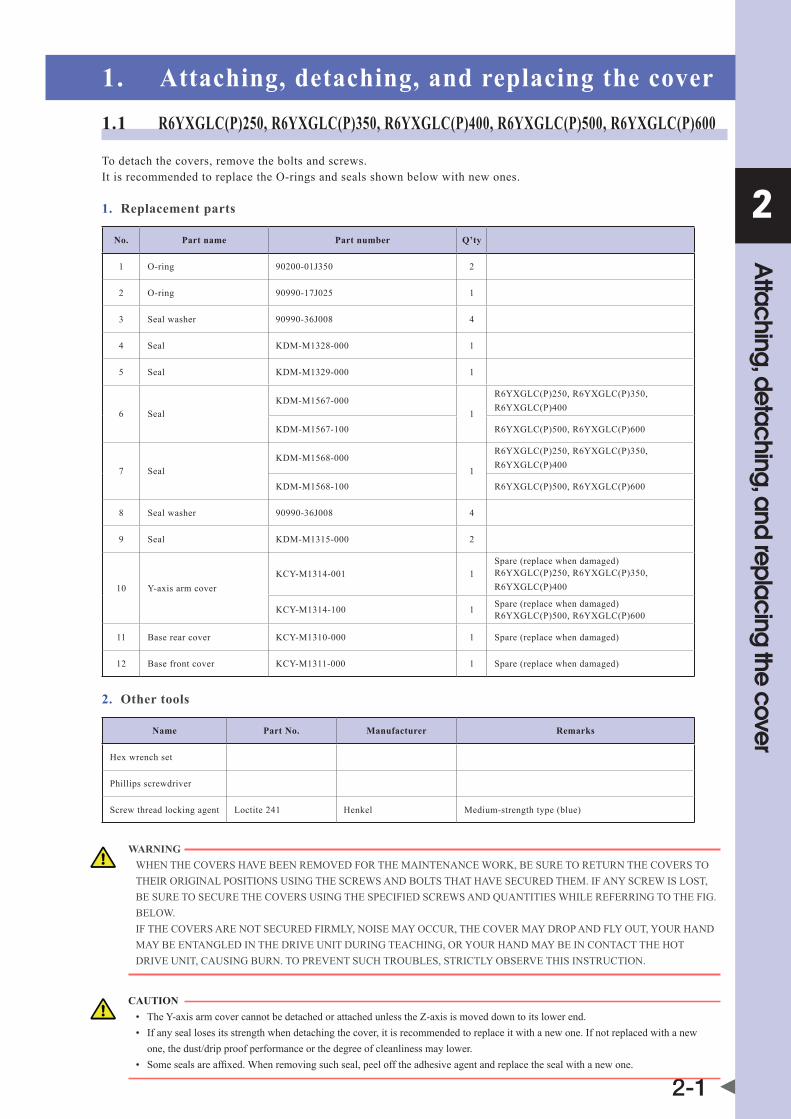
1. Attaching, detaching, and replacing the cover1.1 R6YXGLC(P)250, R6YXGLC(P)350, R6YXGLC(P)400, R6YXGLC(P)500, R6YXGLC(P)600
To detach the covers, remove the bolts and screws. It is recommended to replace the O-rings and seals shown below with new ones.
1. Replacement parts
No. Part name Part number Q’ty
1 O-ring 90200-01J350 2
2 O-ring 90990-17J025 1
3 Seal washer 90990-36J008 4
4 Seal Kdm-m1328-000 1
5 Seal Kdm-m1329-000 1
6 SealKdm-m1567-000
1
R6YXGLC(P)250, R6YXGLC(P)350, R6YXGLC(P)400
Kdm-m1567-100 R6YXGLC(P)500, R6YXGLC(P)600
7 SealKdm-m1568-000
1
R6YXGLC(P)250, R6YXGLC(P)350, R6YXGLC(P)400
Kdm-m1568-100 R6YXGLC(P)500, R6YXGLC(P)600
8 Seal washer 90990-36J008 4
9 Seal Kdm-m1315-000 2
10 Y-axis arm coverKCY-m1314-001 1
Spare (replace when damaged) R6YXGLC(P)250, R6YXGLC(P)350, R6YXGLC(P)400
KCY-m1314-100 1 Spare (replace when damaged)R6YXGLC(P)500, R6YXGLC(P)600
11 Base rear cover KCY-m1310-000 1 Spare (replace when damaged)
12 Base front cover KCY-m1311-000 1 Spare (replace when damaged)
2. Other tools
Name Part No. Manufacturer Remarks
Hex wrench set
Phillips screwdriver
Screw thread locking agent Loctite 241 Henkel Medium-strength type (blue)
WARNING WhEnThECovERshavEbEEnREmovEdFoRThEmaInTEnanCEWoRK,bEsUREToRETURnThECovERsToThEIRoRIGInaLPosITIonsUsInGThEsCREWsandboLTsThaThavEsECUREdThEm.IFanYsCREWIsLosT,bEsURETosECUREThECovERsUsInGThEsPECIFIEdsCREWsandqUanTITIEsWhILEREFERRInGToThEFIG.bELoW. IFThECovERsaREnoTsECUREdFIRmLY,noIsEmaYoCCUR,ThECovERmaYdRoPandFLYoUT,YoURhandmaYbEEnTanGLEdInThEdRIvEUnITdURInGTEaChInG,oRYoURhandmaYbEInConTaCTThEhoTdRIvEUnIT,CaUsInGbURn.ToPREvEnTsUChTRoUbLEs,sTRICTLYobsERvEThIsInsTRUCTIon.
CAUTION • TheY-axisarmcovercannotbedetachedorattachedunlessthez-axisismoveddowntoitslowerend. • Ifanyseallosesitsstrengthwhendetachingthecover,itisrecommendedtoreplaceitwithanewone.Ifnotreplacedwithanew one, the dust/drip proof performance or the degree of cleanliness may lower. • somesealsareaffixed.Whenremovingsuchseal,peelofftheadhesiveagentandreplacethesealwithanewone.
2
Attaching, detaching, and replacing the cover
2-2
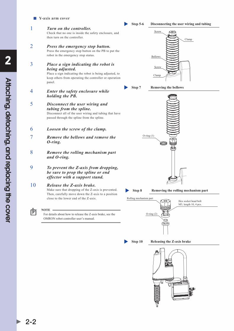
■ Y-axis arm cover
1 Turn on the controller.Check that no one is inside the safety enclosure, and then turn on the controller.
2 Press the emergency stop button.Press the emergency stop button on the PB to put the robot in the emergency stop status.
3 Place a sign indicating the robot is being adjusted.Place a sign indicating the robot is being adjusted, to keep others from operating the controller or operation panel.
4 Enter the safety enclosure while holding the PB.
5 Disconnect the user wiring and tubing from the spline.Disconnect all of the user wiring and tubing that have passed through the spline from the spline.
6 Loosen the screw of the clamp.
7 Remove the bellows and remove the O-ring.
Removing the bellowsStep 7
O-ring (1)
8 Remove the rolling mechanism part and O-ring.
Removing the rolling mechanism partStep 8
O-ring (2)
Rolling mechanism partHex socket head boltM3, length 10, 4 pcs.
9 To prevent the Z-axis from dropping, be sure to prop the spline or end effector with a support stand.
10 Release the Z-axis brake.Make sure that dropping of the Z-axis is prevented. Then, carefully move down the Z-axis to a position close to the lower end of the Z-axis.
Releasing the Z-axis brakeStep 10
NOTE For details about how to release the Z-axis brake, see the OMRON robot controller user’s manual.
Disconnecting the user wiring and tubingStep 5-6
Clamp
Screw
Screw
Bellows
Clamp

2
Attaching, detaching, and replacing the cover
2-3
11 Turn off the controller.
12 Remove the mounting bracket, disconnect the connector for the user wiring, and remove the plate, seal, and seal washer.
Disconnecting the connector for the user wiring and removing the plate, seal, and seal washer.Step 12
Seal (4)
Seal (5)
Connector for user wiring
Hex socket head boltM3, length 6, stainless, 2 pcs.Apply screw lock (LOCTITE) to the bolt threads (first 3 threads)
Y-axis arm cover clamping boltHex socket head boltM3, length 18, stainless, 4 pcs.
Seal washer (3)
Plate
Mounting bracket
13 Remove the cover, seal (6), and seal (7).Since the seal (7) is affixed to the Y-axis arm, peel off the adhesive agent completely.
Removing the cover and sealStep 13
Boss (inside)
Cover (10)
Seal (6)
Y-axis arm cover clamping screwBinding head screw M3, length 12, 4 pcs.
Y-axis arm
Seal washer (8)
Stay
Seal (7)(Adhesion surface is located at the lower portion.)
Cautions on detaching or attaching the coversStep 13
Place the cover so thatit is not damaged.
CAUTION When detaching or attaching the cover, it may be in contact with the boss inside the cover or the stay. So, install the cover while widening it slightly or shifting it.

2
Attaching, detaching, and replacing the cover
2-4
14 Place the cover on the base side. Placing the coverStep 14
Place the cover so thatit is not damaged.15 Reattach the cover in the reverse
order of detachment.It is recommended to replace the O-rings and seals with new ones. If these parts are not replaced or reattached, the dust/drip proof performance or the degree of cleanliness may lower. For details about the bellows clamp position, see the Fig. on the right.
3
12 1.5
ClampStep 15
The bellows end face is flush with the clamp ring end face.
Clamp ring
Clamp ring
Rubber
Rubber
Bellows end face
* Install the bellows and clamp at the positions shown in the Fig. above. (Tolerance: ±0.5mm)
Almost this orientation
Rubber
Reattach the clamp so that the projection part of the clamp shown in the Photo is located in the clearance of the black rubber.
2
Attaching, detaching, and replacing the cover
2-5
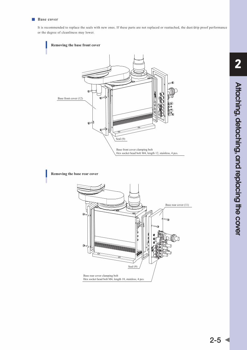
■ Base cover
It is recommended to replace the seals with new ones. If these parts are not replaced or reattached, the dust/drip proof performance or the degree of cleanliness may lower.
Removing the base front cover
Seal (9)
Base front cover (12)
Base front cover clamping boltHex socket head bolt M4, length 12, stainless, 4 pcs.
Removing the base rear cover
Seal (9)
Base rear cover (11)
Base rear cover clamping boltHex socket head bolt M4, length 18, stainless, 4 pcs.

2
Attaching, detaching, and replacing the cover
2-6
1.2 R6YXGP500, R6YXGP600, R6YXGHP600, R6YXGP700, R6YXGP800, R6YXGP900, R6YXGP1000
•ListofY-axisarmcoverseals
No. Part name Part number Q’ty
1 Seal washer 90990-28J159 14 R6YXGP500 Z200, R6YXGP600 Z200
2 Seal washer 90990-28J159 16 R6YXGP500 Z300, R6YXGP600 Z300
3 Seal washer 90990-28J159 18 R6YXGHP600 Z200 to R6YXGP1000 Z200
4 Seal washer 90990-28J159 22 R6YXGHP600 Z400 to R6YXGP1000 Z400
5 Seal Kad-m22Kb-100(690mm + 480mm) R6YXGP500 Z200, R6YXGP600 Z200
6 Seal Kad-m22Kb-100(890mm + 480mm) R6YXGP500 Z300, R6YXGP600 Z300
7 Seal Kad-m22Kb-100(750mm + 550mm) R6YXGHP600 Z200 to R6YXGP1000 Z200
8 Seal Kad-m22Kb-100(1150mm + 550mm) R6YXGHP600 Z400 to R6YXGP1000 Z400
•Listofbasecoverseals
No. Part name Part number Q’ty
1 Seal Kdn-m1315-00x 2 R6YXGP500, R6YXGP600
2 Seal KdP-m1315-00x 2R6YXGHP600, R6YXGP700, R6YXGP800, R6YXGP900, R6YXGP1000
To detach the covers, remove the bolts and screws shown in the Fig. below.
WARNING WhEnThECovERshavEbEEnREmovEdFoRThEmaInTEnanCEWoRK,bEsUREToRETURnThECovERsToThEIRoRIGInaLPosITIonsUsInGThEsCREWsandboLTsThaThavEsECUREdThEm. IFanYsCREWIsLosT,UsEThEsPECIFIEdsCREWsandqUanTITIEsTosECUREThECovERsWhILEREFERInGToThEFIG.bELoW. IFThECovERsaREnoTsECUREdFIRmLY,noIsEmaYoCUR,ThECovERmaYdRoPandFLYoUT,YoURhandmaYbEEnTanGLEdInThEdRIvEUnITdURInGTEaChInG,oRYoURhandmaYbEInConTaCTThEhoTdRIvEUnIT,CaUsInGbURn.ToPREvEnTsUChTRoUbLEs,sTRICTLYobsERvEThIsCaUTIon.
CAUTION • TheY-axisarmcovercannotbedetachedorattachedunlessthez-axisismoveddowntoitslowerend. • Ifanyseallosesitsstrengthwhendetachingthecover,itisrecommendedtoreplaceitwithanewone.Ifnotreplacedwithanew one, the dust/drip proof performance or the degree of cleanliness may lower. • somesealsareaffixed.Whenremovingsuchseal,peelofftheadhesiveagentandreplacethesealwithanewone.

2
Attaching, detaching, and replacing the cover
2-7
R6YXGP500, R6YXGP600
Base front coverSeal
Y-axis arm cover
Y-axis arm cover side-face securing screwsHex socket head bolt M3×8 stainlessSeal washer
Base front cover securing screwsHex socket head bolt M4×8 stainless
Base rear cover securing screwsHex socket head bolt M4×25 stainless
Y-axis arm cover securing screws (front side)Hex socket head bolt M3×20 stainlessSeal washer
Y-axis arm cover rear plate securing screws & seal washersHex socket head bolt M3×8 stainlessSeal washer
Base rear coverSeal
R6YXGHP600, R6YXGP700, R6YXGP800, R6YXGP900, R6YXGP1000
Base front cover seal
Y-axis arm cover
Y-axis arm cover side-face securing screwsHex socket head bolt M3×8 stainlessSeal washer
Base front cover securing screwsHex socket head bolt M4×10 stainless
Base rear cover securing screwsHex socket head bolt M4×20 stainless
Y-axis arm cover securing screws (front side)Z200 : Hex socket head bolt M3×20 stainlessZ400 : Hex socket head boltM3×50 stainlessCommon: seal washers
Y-axis arm cover rear plate securing screws & seal washersHex socket head bolt M3×8 stainlessSeal washer
Base rear cover


Chapter 3 Periodic inspection
Contents
1. Periodic inspection 3-11.1 Six-month inspection 3-1
2. Applying the grease 3-32.1 Applying the grease to the spline shaft 3-3
2.2 Applying the grease to the ball screw 3-4


3
Perio
dic
inspe
ctio
n
3-1
1. Periodic inspectionThis chapter describes only the points that are different from the standard models. For details about other explanations and cautions, see the maintenance manual for XG series standard models.
1.1 Six-month inspection
For details about cautions on inspection work, see the maintenance manual for XG standard models.
■ Inspection to be performed with the controller turned off
1 Turn off the controller.
2 Place a sign indicating the robot is being adjusted.Place a sign showing that the robot is being inspected, to keep others from operating the controller switch.
3 Perform the daily inspection.Enterthesafetyenclosureandcheckthefollowingpoints.
Checkpoint Procedure
Manipulator bolts and screws (Only for major bolts and screws exposed externally)
Check for looseness and tighten if necessary. (See the Table below.)
ControllerCheck for looseness at each terminal and connector on the panel. (See “4. Robot cable connection” in Chapter 2 of the Installation Manual.)
Application of grease to Z-axis ball screw and spline
See “2. Applying the grease” in this chapter.
Z-axis ball spline, ball screw Check for backlash. (If any abnormality is found, contact your distributor.)
Bellows Check for breakage.
Bolt tightening torque
Bolt size Tightening torque (kgfcm) Tightening torque (Nm)
M3 button head bolt 14 1.4
M4 set screw 20 2.0
M3 20 2.0
M4 46 4.5
M5 92 9.0
M6 156 15.3
M8 380 37
M10 459 45.0
M12 1310 128
M14 2090 205

3
Perio
dic
inspe
ctio
n
3-2
■ Inspection to be performed with the controller turned on
WARNING • ThERoboTConTRoLLERmUsTbEInsTaLLEdoUTsIdEThEsaFETYEnCLosURE,ToPREvEnTahazaRdoUs sITUaTIonInWhIChYoUoRanYonEEnTERThEsaFETYEnCLosUREToInsPECTThEConTRoLLERWhILE ITIsTURnEdon. • bodILYInJURYmaYoCCURFRomComInGInToConTaCTWIThThEFanWhILEITIsRoTaTInG. • WhEnREmovInGThEFanCovERFoRInsPECTIon,FIRsTTURnoFFThEConTRoLLERandmaKEsUREThE FanhassToPPEd.
1 Turn on the controller.Check that no one is inside the safety enclosure, and then turn on the controller.
2 Place a sign indicating the robot is being adjusted.Place a sign indicating the robot is being inspected, to keep others from operating the controller, programming box or operation panel.
3 Perform the daily inspection.Check the following points from outside the safety enclosure.
Checkpoint Procedure
Cooling fan at rear of controller
• Checkifthefanrotatesnormally. • Checkifobjectsblockingthefanarelocatedandremoveifanyarefound. • Checkforabnormalnoisefromtherotatingfan.Ifabnormalnoiseisheard,visually check and remove the cause. If no cause is found, contact your distributor . • Checkfordustonthefancover.Removeandcleanifnecessary.
■ Adjustment and parts replacement
CAUTION • afterinspection,ifyounoticeanyadjustmentorpartsreplacementisneeded,firstturnoffthecontrollerandthenenterthesafety enclosure to perform the necessary work. o perform the inspection after the adjustment and parts replacement work, follow the steps stated in “n Inspection to be performed with the controller turned off” and “n Inspection to be performed with the controller turned on” described above. • Ifrepairorpartsreplacementisrequiredfortherobotorcontroller,pleasecontactyourdistributor.Thisworkrequiresspecialized technical knowledge and skill, so do not attempt it by yourself.

3
Perio
dic
inspe
ctio
n
3-3
2. Applying the grease2.1 Applying the grease to the spline shaftFollow the steps below to apply the grease to the spline shaft.
1 Turn off the controller power.Move down the Z-axis to its lower end and turn off the controller power.
2 Place a sign indicating the robot is being adjusted.Place a sign indicating the robot is being adjusted, to keep others from operating the controller or operation panel.
3 Enter the safety enclosure.
4 Remove the lower bellows.Remove the lower bellows as described in Chapter 7 "2. Replacing the lower bellows". There is no need to remove the bellows on the following models: R6YXGP500, R6YXGP600, R6YXGHP600, R6YXGP700, R6YXGP800, R6YXGP900, R6YXGP1000. Remove the screws (M3 × 8 screws) which secure the upper part of the bellows, then, with the bellows lowered, apply the grease.
5 Remove the old grease with a cloth rag.
6 Apply the grease.Apply the grease to the spline shaft of the Z-axis.
CleanroomspecificationsR6YXG(L)Cgrease: LG2(nsK) Dust/drip proof specifications R6YXG(L)P grease: Alvania S2 grease (Showa Shell)
Applying the grease
Lower the spline and apply grease to the groove.
3
Perio
dic
inspe
ctio
n
3-4
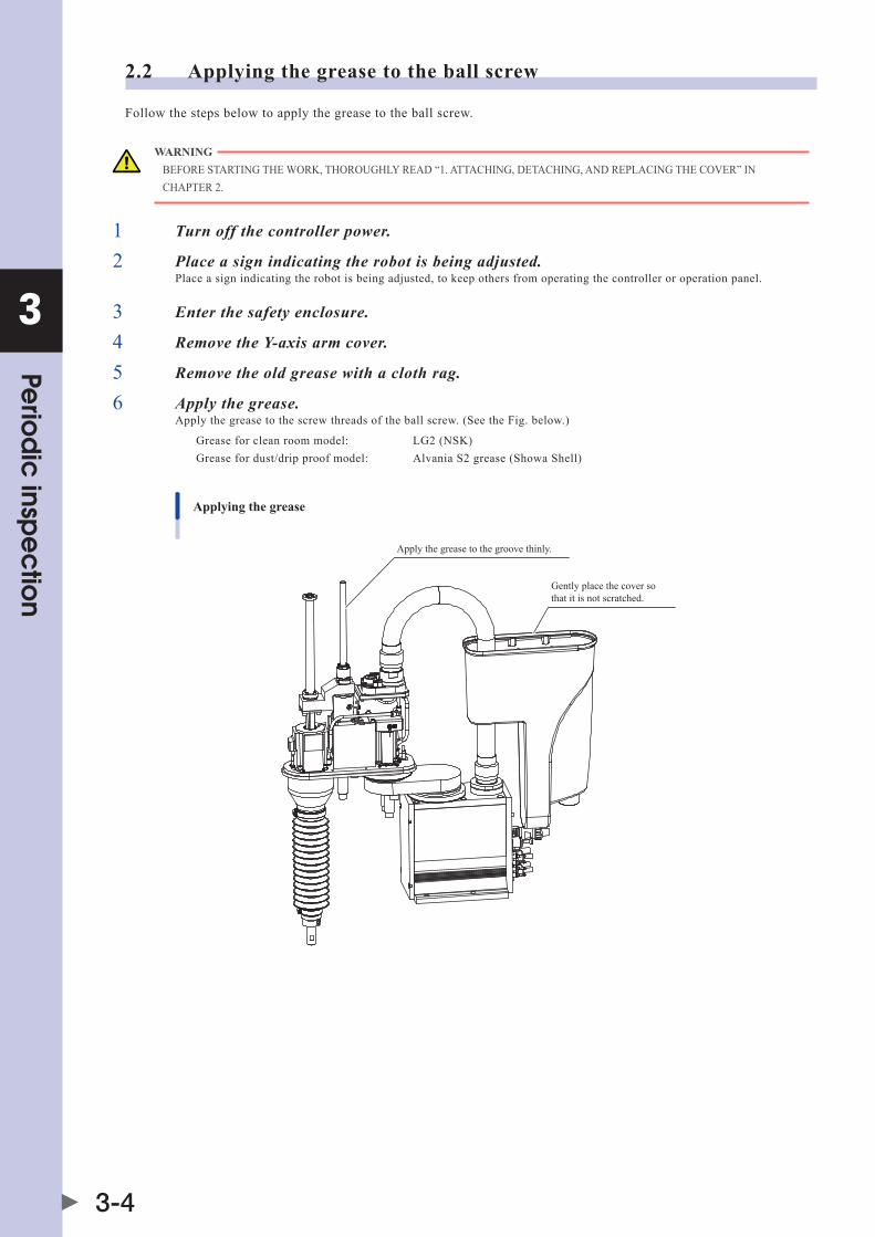
2.2 Applying the grease to the ball screw
Follow the steps below to apply the grease to the ball screw.
WARNING bEFoREsTaRTInGThEWoRK,ThoRoUGhLYREad“1.aTTaChInG,dETaChInG,andREPLaCInGThECovER”InChaPTER2.
1 Turn off the controller power.
2 Place a sign indicating the robot is being adjusted.Place a sign indicating the robot is being adjusted, to keep others from operating the controller or operation panel.
3 Enter the safety enclosure.
4 Remove the Y-axis arm cover.
5 Remove the old grease with a cloth rag.
6 Apply the grease.Apply the grease to the screw threads of the ball screw. (See the Fig. below.)
Greaseforcleanroommodel: LG2(nsK) Grease for dust/drip proof model: Alvania S2 grease (Showa Shell)
Applying the grease
Apply the grease to the groove thinly.
Gently place the cover so that it is not scratched.

Chapter 4 Robot settings
Contents
1. Overview 4-1
2. Adjusting the origin 4-2
3. Standard coordinate setting using a standard coordinate setup jig 4-33.1 R6YXGLC(P)250, R6YXGLC(P)350, R6YXGLC(P)400, R6YXGLC(P)500, R6YXGLC(P)600 4-3
3.2 R6YXGP500, R6YXGP600, R6YXGHP600, R6YXGP700, R6YXGP800, R6YXGP900, R6YXGP1000 4-4


4
Rob
ot se
ttings
4-1
1. Overviewvarioussettingshavebeencompletelymadeatthefactoryorbyyourdistributorbeforeshipment,includingtheoriginposition setting. If the operating conditions are changed and the robot needs to be set again, then follow the procedures described in this chapter.
The following describes the safety precautions to be observed when making various settings.
CAUTION • Readandunderstandthecontentsofthischaptercompletelybeforeattemptingtosettherobot. • Placeaconspicuoussignindicatingtherobotisbeingadjusted,topreventothersfromtouchingthecontrollerswitch,programming box or operation panel. • Ifasafetyenclosurehasnotyetbeenprovidedrightafterinstallationoftherobot,ropeofforchainoffthemovementareaaroundthe manipulator in place of a safety enclosure, and observe the following points. 1. Use stable posts which will not fall over easily. 2. The rope or chain should be easily visible by everyone around the robot. 3. Place a conspicuous sign prohibiting the operator or other personnel from entering the movement area of the manipulator. • Tochecktheoperationafterthesettingshavebeenmade,refertothesection"4.5.1Trialoperation"inChapter"safetyInstructions" of this manual.
This chapter describes only the points that are different from the standard models. For details about other explanations, see the installation manual for XG series standard models.

4
Rob
ot se
ttings
4-2
2. Adjusting the originThis section describes only the origin adjustment points that are different from the standard models. For details about other explanations, see the installation manual for XG series standard models.
■ Adjusting the origin of the R6YXGLC(P)250, R6YXGLC(P)350, R6YXGLC(P)400, R6YXGLC(P)500 or R6YXGLC(P)600
• sincethejointsoftheX-,Y-,andR-axisarecovered,itisdifficulttounderstandtheclearancebetweenthesensoranddog.After the origin has been adjusted in the same manner as the standard model, touch the arm, etc. to carefully adjust the machine reference so that the origin does not deviate. After the machine reference has been adjusted, turn the joint to check that the sensor does not collide with the dog.
• sincethejointsarecovered,theoriginpositionsoftheX-axisandY-axiscannotbechanged.
• TheR-axissensorusesacompactsensor.so,carefullycheckthatthetighteningtorqueofthehexnutisassmallas1nm(10kgfcm). If tightened to a torque larger than this level, the sensor may break.
R-axis origin sensor and hex nut
R-axis origin sensor
Hex nut

4
Rob
ot se
ttings
4-3
3. Standard coordinate setting using a standard coordinate setup jig3.1 R6YXGLC(P)250, R6YXGLC(P)350, R6YXGLC(P)400, R6YXGLC(P)500, R6YXGLC(P)600Use a standard coordinate setup jig (option) to set the standard coordinates more accurately.The following describes how to set the standard coordinates using the standard coordinate setup jig.
Standard coordinate setup jig (option)
Part No. Name Q'ty
1 KCY-m1577-000 Pin 1
2 91312-04065 Bolt 1
1 Turn on the controller.Check that no one is inside the safety enclosure, and then turn on the controller.
2 Put the robot in the emergency stop status.Press the emergency stop button on the PB to put the robot in the emergency stop status.
NOTE For details about emergency stop and how to cancel the emergency stop, see the "OMRON Robot Controller User's Manual".
3 Place a sign indicating the robot is being adjusted.Place a sign indicating the robot is being adjusted, to keep others from operating the controller or operation panel.
4 Enter the safety enclosure while holding the PB.
5 Remove the plug bolt and seal washer.Put the robot in the posture with the positional relationship between the Y-axis arm and the X-axis arm as shown in the Fig. on the right, and then remove the plug bolt and seal washer.
Plug bolt
Enlarged hole
Hole
Seal washer
Removing the plug boltStep 5
6 Insert the pin (1).1. Put the robot in the arm posture allowing
insertion of the pin, and make the X-axis arm almost aligned with the Y-axis.
2. Adjust the arm positions so that the pin can be inserted into the enlarged hole in the Y-axis arm and the hole in the X-axis arm without jamming, and then insert the pin into the holes.
Bolt (2)
Pin (1)
Y-axis position pulse valueStep 6-8
7 Secure the pin (1) with the bolt (2).Tighten the bolt so that the pin does not move.

4
Rob
ot se
ttings
4-4
8 Make a note of the Y-axis position pulse value.1. Enter"manUaL>PoInT"mode.
2. Lightly apply a clockwise torque to the Y-axis while holding the X-axis arm.
3. Make a note of the Y-axis position pulse value displayed on [POS] when the torque is unloaded.
4. Lightly apply a counterclockwise torque to the Y-axis while holding the X-axis arm.
5. Make a note of the Y-axis position pulse value displayed on [POS] when the torque is unloaded.
9 Determine the + direction of the X-axis.Move the X-axis arm in the direction that you want to set as the + direction of the X-axis. At this time, make a note of the X-axis position pulse value displayed on [POS].
X-axis + directionStep 9
+Y direction
+X direction
10 Enter the "11. Arm length [mm]" values.Enterthefollowingvaluesinm1andm2for"11.Arm length [mm]" of axis parameters.
M1 (X-axis arm length) M2 (Y-axis arm length)
R6YXGLC(P)250 100.00 150.00
R6YXGLC(P)350 200.00 150.00
R6YXGLC(P)400 250.00 150.00
R6YXGLC(P)500 250.00 250.00
R6YXGLC(P)600 350.00 250.00
11 Enter the "12. Offset pulse" values.Enterthevaluesshownontherightin"12.offsetpulse" of axis parameters.
Entering the “12. Offset pulse” valuesStep 11
Note: Round off the decimal part of the M2 value.
M1= X-axis position pulse value you have made a note of in step 9
2M2=
+Y-axis position pulse value you have made a note of in step 8 (clockwise)
Y-axis position pulse value you have made a note of in step 8 (counterclockwise)12 Reattach the plug bolt and seal
washer.1. Remove the pin and bolt.
2. Reattach the plug bolt and seal washer.
3.2 R6YXGP500, R6YXGP600, R6YXGHP600, R6YXGP700, R6YXGP800, R6YXGP900, R6YXGP1000Refer to the maintenance manual for XG series standard models with regard to the following models: R6YXGP500, R6YXGP600, R6YXGHP600, R6YXGP700, R6YXGP800, R6YXGP900, R6YXGP1000.

Chapter 5 Replacing the harmonic drive
Contents
1. Cautions on replacement of the harmonic drive 5-1
2. Replacement procedure for harmonic drive 5-22.1 R6YXGLC(P)250, R6YXGLC(P)350, R6YXGLC(P)400, R6YXGLC(P)500, R6YXGLC(P)600 5-3
2.1.1 Replacing the X-axis harmonic drive 5-32.1.2 Replacing the Y-axis harmonic drive 5-122.1.3 Replacing the R-axis harmonic drive 5-18
2.2 R6YXGP500, R6YXGP600, R6YXGHP600, R6YXGP700, R6YXGP800, R6YXGP900, R6YXGP1000 5-29
2.2.1 Replacing the X-axis harmonic drive 5-292.2.2 Replacing the Y-axis harmonic drive 5-382.2.3 Replacing the R-axis harmonic drive 5-49


5
Rep
lac
ing the
harm
onic
drive
5-1
1. Cautions on replacement of the harmonic driveThe following describes the cautions on replacement of the harmonic drive. Before beginning the replacement work, always be sure to read these replacement procedures and caution.
■ Cautions on replacement of the harmonic drive
WARNING • ThEmoToRandsPEEdREdUCTIonGEaRCasInGaREEXTREmELYhoTaFTERaUTomaTICoPERaTIon,so bURnsmaYoCCURIFThEsEaREToUChEd.bEFoREToUChInGThEsEPaRTs,TURnoFFThEConTRoLLER, WaITFoRaWhILEandChECKThaTThETEmPERaTUREhasCooLEd. • WhEnREmovInGThEWavEGEnERaToRFRomThEmoToRshaFToRREInsTaLLInGITbaCKonToThE moToRshaFT,UsECaUTIonToavoIdasmUChasPossIbLE,aPPLYInGaThRUsTLoadToThEmoToR shaFT.IFaLoadIsaPPLIEd,ThEREsoLvERmaYbEdamaGEdREsULTInGInahazaRdoUssITUaTIonoF ThERoboTTRoUbLE. PRECaUTIonsWhEnhandLInGhaRmonICGREasE,CLEanInGoIL: • InFLammaTIonmaYoCCURIFThEYGETInThEEYEs.bEFoREhandLInGThEm,WEaRYoURsaFETY GoGGLEsToEnsUREThEYWILLnoTComEInConTaCTWIThThEEYEs. • InFLammaTIonmaYoCCURIFThEYComEInToConTaCTWIThsKIn.bEsUREToWEaRPRoTECTIvE GLovEsToPREvEnTConTaCTWIThsKIn. • donoTTaKEoRaLLYoREaT.(EaTInGWILLCaUsEdIaRRhEaandvomITInG.) • handsandFInGERsmIGhTbECUTWhEnoPEnInGThEConTaInER,soUsEPRoTECTIvEGLovEs. • KEEPoUToFThEREaChoFChILdREn. • donoThEaTThEmoRPLaCEnEaRanoPEnFLamEsInCEThIsCoULdLEadTosPaRKsandFIREs. EmERGEnCYTREaTmEnT: • IFThEYGETInThEEYEs,WashLIbERaLLYWIThPUREWaTERFoRaboUT15mInUTEsandConsULTa PhYsICIanFoRTREaTmEnT. • IFThEYComEInConTaCTWIThThEsKIn,WashaWaYComPLETELYWIThsoaPandWaTER. • IFTaKEnInTERnaLLY,donoTIndUCEvomITInGbUTPRomPTLYConsULTaPhYsICIanFoRTREaTmEnT. dIsPosInGoFhaRmonICGREasE,CLEanInGoILandThEConTaInER: • PRoPERdIsPosaLIsComPULsoRYUndERFEdERaL,sTaTEandLoCaLREGULaTIons.TaKEaPPRoPRIaTE mEasUREsInComPLIanCEWIThLEGaLREGULaTIons. • donoTPREssURIzEThEEmPTYConTaInER.PREssURIzInGmaYCaUsEThEConTaInERToRUPTURE. • donoTaTTEmPTToWELd,hEaTUP,dRILLhoLEsoRCUTThIsConTaInER.ThIsmIGhTCaUsEThE ConTaInERToEXPLodEandThEREmaInInGmaTERIaLsInsIdEITToIGnITE.
CAUTION The harmonic drive service life may shorten if the grease recommended by OMRON is not used.
■ Recommended grease
Use the following harmonic drive grease.
4B No.2 (made by Harmonic Drive Systems Inc.)
CAUTION Harmonic drive • donotapplystrongshocksorimpactstothesepartssuchaswithahammer.also,donotscratch,scarordentthesepartsby dropping, etc. Such actions will damage the harmonic drive. • Thespecifiedperformancecannotbemaintainedifanypartoftheharmonicdriveisusedinadamagedstate.Thisdamageorwear may also lead to trouble with the harmonic drive. • sinceapositionalshiftoccursafterreplacingtheharmonicdrive,itisnecessarytomakeabsolutereset,standardcoordinatesetting and point data setting again.

5
Rep
lac
ing the
harm
onic
drive
5-2
2. Replacement procedure for harmonic driveThe following describes the procedures and precautions for replacing the harmonic drive. For the bolt tightening torque in the harmonic drive replacement work, see the Table below. However, when tightening the mounting bolts for the harmonic drive, observe the tightening torque specified in each replacement procedure. Use only OMRON genuine bolts.
■ Bolt tightening torque
Bolt size Tightening torque (kgfcm) Tightening torque (Nm)
M3 button head bolt 14 1.4
M4 set screw 20 2.0
M3 20 2.0
M4 46 4.5
M5 92 9.0
M6 156 15.3
M8 380 37
M10 720 71
Recommended"screwLock":LoCTITE262(madebyhenkelCorporation)
CAUTION somesealsareaffixed.Whenremovingsuchseal,peelofftheadhesiveagentandreplacethesealwithanewone.
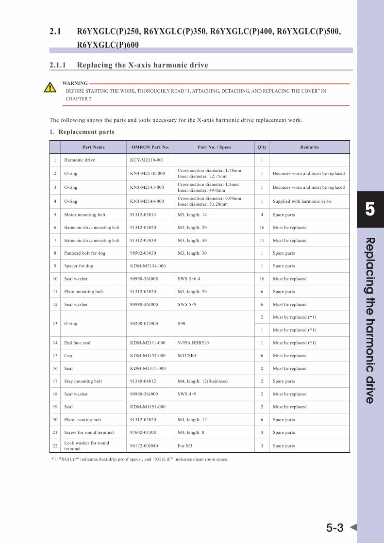
5
Rep
lac
ing the
harm
onic
drive
5-3
2.1 R6YXGLC(P)250, R6YXGLC(P)350, R6YXGLC(P)400, R6YXGLC(P)500, R6YXGLC(P)600
2.1.1 Replacing the X-axis harmonic drive
WARNING bEFoREsTaRTInGThEWoRK,ThoRoUGhLYREad“1.aTTaChInG,dETaChInG,andREPLaCInGThECovER”InChaPTER2.
The following shows the parts and tools necessary for the X-axis harmonic drive replacement work.
1. Replacement parts
Part Name OMRON Part No. Part No. / Specs Q'ty Remarks
1 Harmonic drive KCY-m2110-001 1
2 O-ring Kn4-m257K-000 Cross section diameter: 1.78mm Inner diameter: 72.75mm 1 Becomes worn and must be replaced
3 O-ring Kn3-m2143-000 Cross section diameter: 1.5mm Inner diameter: 49.0mm 1 Becomes worn and must be replaced
4 O-ring Kn3-m2144-000 Cross section diameter: 0.99mm Inner diameter: 53.28mm 1 Supplied with harmonic drive
5 Motor mounting bolt 91312-05014 M5, length: 14 4 Spare parts
6 Harmonic drive mounting bolt 91312-03020 M3, length: 20 16 Must be replaced
7 Harmonic drive mounting bolt 91312-03030 M3, length: 30 11 Must be replaced
8 Panhead bolt for dog 98502-03030 M3, length: 30 1 Spare parts
9 Spacer for dog Kdm-m2134-000 1 Spare parts
10 Seal washer 90990-36J008 SWS 3×6.4 16 Must be replaced
11 Plate mounting bolt 91312-05020 M5, length: 20 6 Spare parts
12 Seal washer 90990-36J006 SWS 5×9 6 Must be replaced
13 O-ring 90200-01J900 S902 Must be replaced (*1)
1 Must be replaced (*1)
14 Endfaceseal Kdm-m2111-000 v-95anbR510 1 Must be replaced (*1)
15 Cap Kdm-m1152-000 MTCSB5 6 Must be replaced
16 Seal Kdm-m1315-000 2 Must be replaced
17 Stay mounting bolt 91380-04012 M4, length: 12(Stainless) 2 Spare parts
18 Seal washer 90990-36J009 SWS 4×9 2 Must be replaced
19 Seal Kdm-m1151-000 2 Must be replaced
20 Plate securing bolt 91312-05020 M4, length: 12 6 Spare parts
21 Screw for round terminal 97602-04308 M4, length: 8 3 Spare parts
22 Lock washer for round terminal 90172-00J040 For M3 3 Spare parts
*1: "XG(L)P" indicates dust/drip proof specs., and "XG(L)C" indicates clean room specs.

5
Rep
lac
ing the
harm
onic
drive
5-4
2. Torque wrench, etc.
CAUTION Use accurately calibrated torque screwdrivers and torque wrenches.
Name Part No. Manufacturer Remarks
ATorque wrench n120sPCK Kanon
(Nakamura Mfg. Co., Ltd.)For M5 hex socket head bolt Tightening torque: 7.4Nm (76kgfcm)
Changeable head 230hCK4 Kanon (Nakamura Mfg. Co., Ltd.)
Wrench (without ball end) for M5 hex socket head bolt; insert 110mm
B
Torque screwdriver n30LTdK Kanon (Nakamura Mfg. Co., Ltd.)
For M3 hex socket head bolt Tightening torque: 1.8Nm (18kgfcm)
Drive bit B35, opposite side 2.5×75 vesselCo.,Inc.
Attachment hexagonal width across flat : 6.35mm Overall length : 75mm Hexagonal width across flat at tip : 2.5mm
C
Torque screwdriver n12LTdK Kanon (Nakamura Mfg. Co., Ltd.)
For M3 set screw Tightening torque: 0.7Nm (7kgfcm)
Drive bit 3C1507 NAC (Nagahori Industry Co., Ltd.)
Attachment hexagonal width across flat : 6.35mm Overall length : 70mm Hexagonal width across flat at tip : 1.5mm
D
Torque screwdriver n12LTdK Kanon (Nakamura Mfg. Co., Ltd.)
For M3 Phillips-head screw Tightening torque: 0.9Nm (9kgfcm)
Drive bit B35+2×50 vesselCo.,Inc.Attachment hexagonal width across flat : 6.35mm Overall length : 50mm Bit numbe r: #2
* Use a commercially available torque wrench to tighten bolts other than those shown above.
3. Other tools
Name Part No. Manufacturer Remarks
Harmonic grease 4B No.2 (*1) Harmonic Drive Systems Do not use grease if it was purchased 4 or more years ago. The grease has probably deteriorated.
Cleaning wipe
Phillips screwdriver
Hex wrench set
"screwLock"LoCTITE Loctite 262 Henkel High strength type (red)
*1 : 25g
■ RemovalFollow the steps below to remove the X-axis parts.
1 Turn off the controller.
2 Place a sign indicating the robot is being adjusted.Place a sign indicating the robot is being adjusted, to keep others from operating the controller or operation panel.
3 Enter the safety enclosure.
CAUTION In the following steps, when the work is performed without removing the Y-axis arm from the X-axis arm, perform the work with great care since the X-arm without removing the Y-axis arm is very heavy.
4 Remove the base front and rear covers, and seals.
Removing the base covers and sealsStep 4
Bolt M4×12
Cover
Bolt M4×18
Cover
Seal
SealNOTE somesealsareaffixed.Whenremovingsuchseal,peeloffthe adhesive agent and replace the seal with a new one.

5
Rep
lac
ing the
harm
onic
drive
5-5
5 Disconnect the X-axis motor power wire XM connector and resolver wire XP connector in the base, and the round terminals of the X-axis motor and machine harness.
6 Remove the machine harness stay mounting bolts and seal washers.
Disconnecting the connectors and round terminals, and removing the mounting bolts, and washersStep 5-6
Stay
Panhead bolt M4×8
Bolt M4×12
Seal washer
Machine harness
Round terminal
* The position of the round terminal may differ according to the model in question.
NOTE Be sure to replace the seal and seal washer with new ones.
7 Remove the plate from the base.1. Remove the caps, bolts, and seal washers from
the top surface of the plate.
2. Remove the seals.
NOTE somesealsorsealwashersareaffixed.Whenremovingsuchseal or seal washer, peel off the adhesive agent and replace the seal or seal washer with a new one.
3. Lay down the plate together with the X-axis and Y-axis arms to place it onto a cloth rag.
Removing the plateStep 7
Seal
Cap
Bolt M5×20
Plate
Seal washer
Base
8 Remove the X-axis motor.1. Disconnect the air tube from the joint.
2. Using the tool A, remove the bolts that secure the motor.
3. Pull out the motor from the plate while turning the X-axis arm.
NOTE An O-ring is placed between the motor mating and the plate. Replace this O-ring with a new one.
Removing the motorStep 8
X-axis motor Air tubeBolt M5×14
O-ringJoint
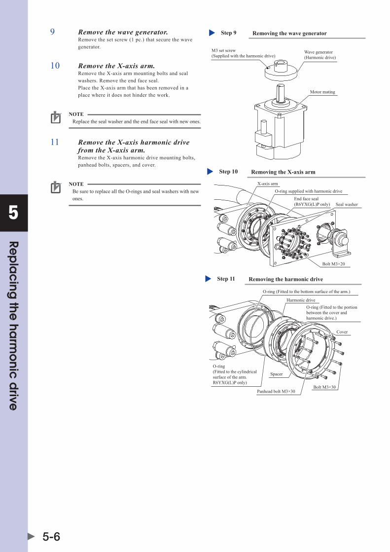
5
Rep
lac
ing the
harm
onic
drive
5-6
9 Remove the wave generator.Remove the set screw (1 pc.) that secure the wave generator.
Removing the wave generatorStep 9
M3 set screw(Supplied with the harmonic drive)
Wave generator(Harmonic drive)
Motor mating
10 Remove the X-axis arm.Remove the X-axis arm mounting bolts and seal washers. Remove the end face seal. Place the X-axis arm that has been removed in a place where it does not hinder the work.
Removing the X-axis armStep 10
Seal washer
Bolt M3×20
O-ring supplied with harmonic drive
End face seal (R6YXG(L)P only)
X-axis arm
NOTE Replace the seal washer and the end face seal with new ones.
11 Remove the X-axis harmonic drive from the X-axis arm.Remove the X-axis harmonic drive mounting bolts, panhead bolts, spacers, and cover.
Removing the harmonic driveStep 11
O-ring (Fitted to the bottom surface of the arm.)
O-ring(Fitted to the cylindrical surface of the arm. R6YXG(L)P only)
Spacer
Bolt M3×30Panhead bolt M3×30
Harmonic drive
Cover
O-ring (Fitted to the portion between the cover and harmonic drive.)
NOTE Be sure to replace all the O-rings and seal washers with new ones.

5
Rep
lac
ing the
harm
onic
drive
5-7
■ Replacement and reassembly
Follow the steps below to replace the harmonic drive with a new one and reassemble it.
1 Perform the work shown below before reassembling the harmonic drive.1. Apply the harmonic grease to a new wave generator. For details about how to apply the grease, see the Fig. below.
Before applying the grease, degrease the top and bottom surfaces of the harmonic drive.
Step 1 Applying the harmonic grease
Temporarily secured bolt
Flex spline
Degrease the installation surface.
Degrease the installation surface.
Circular spline
Wave generator
Fill ball spaces with the grease sufficiently.Apply the grease to the entire surface of Oldham's coupling.Total grease amount: 3 g
Apply the grease to the gear clearances.
2. Remove the old grease and worn-out particles from the motor, plate, and X-axis arm completely.
CAUTION • Ifforeignmatteriscaughtinduringreassemblywork,thismaycausethenoisefromtheharmonicdriveortheharmonicdriveto break. • neverremovethetemporarilysecuredbolts.doingsomaycauseamisalignment.
2 Secure a new harmonic drive (1) to the X-axis arm.1. Degrease the harmonic drive installation surface of the X-axis arm.
Do not apply the grease to the seating part.
Step 2 Mounting the harmonic drive
Make the bolt matched with the spot facing part of the arm.
New O-ring (2) (Fit to the bottom surface of the arm.)
New O-ring (13) (Fit to the cylindrical surface of the arm. (R6YXG(L)P only))
Spacer (9)
Degrease the harmonic drive mounting surface of the X-axis arm.* Do not apply the grease to the seating part.
O-ring groove
New bolt (7) Tool B
Panhead bolt (8) Tool D* Assemble the panhead bolt at the same position as the X-axis arm during reassembly.
New harmonic drive (1)
New O-ring (13)(Fit to the portion between the cover and harmonic drive.)
Cover
2. Fit the O-ring (2) and O-ring (13) (R6YXG(L)P only) coated with the grease into the O-ring groove of the X-axis arm. Fit another O-ring (13) to the portion between the harmonic drive and cover. Since the grease application to the O-ring is intended to prevent the O-ring from coming off, it is accepted to apply a small amount of the grease.
CAUTION Do not allow the O-ring to get caught out of the groove during reassembly. If the robot is operated with the O-ring left caught out of the groove, this may cause a malfunction.

5
Rep
lac
ing the
harm
onic
drive
5-8
3. Secure the new harmonic drive to the X-axis arm with new bolts. Apply harmonic grease 4B No.2 to the tip of each bolt so that the roots of at least the first four threads are filled with grease. Grease applied to the bolt tip is intended to stabilize the bolt axial force.
4. Secure the panhead bolts and spacers to their original positions.
5. Fit the end face seal.
CAUTION Do not apply the grease to the panhead bolt. Doing so may cause the bolt to loosen.
Applying the grease to the mounting boltStep 2, 5
4B No.2 grease
3 Tighten the bolts and panhead bolts in the order shown below.1. Using the wrench, tighten the bolts and panhead
bolts manually in the order indicated by circled numbers.
2. Using the torque wrench, tighten the bolts and panheadboltstoapproximately50%ofthespecified torque in the order indicated by circled numbers.
3. Tighten the bolts and panhead bolts to the specified torque in the order indicated by circled numbers.
4. Finally, check that the bolts and panhead bolts are tightened to the specified torque.
Bolt and panhead bolt tightening orderStep 3
4 Install the new O-ring (4).1. Degrease the top surface of the plate where the
harmonic drive is to be installed.
CAUTION Do not allow the O-ring to get caught out of the groove during reassembly. If the robot is operated with the O-ring left caught out of the groove, this may cause a malfunction.
2. Fit the new O-ring (4) coated with the harmonic grease into the O-ring groove of the harmonic drive. Since the grease application to the O-ring is intended to prevent the O-ring from coming off, it is accepted to apply a small amount of the grease.
3. Fit the end face seal into the holder. At this time, fit the end face seal so that its seat is closely in contact with the holder.
Installing the harmonic driveStep 4
Seal washer (10)
HolderEnd face seal is closely in contact with the holder.End face seal (14)
(Carefully check the orientation.)
New bolt (6) Tool B
Degrease the top surface of the plate where the harmonic drive is to be installed.
Temporarily secured bolt
O-ring (4) supplied with the harmonic drive
End face seal (14)(R6YXG(L)P only)
X-axis armDo not apply the grease to the seating surface.

5
Rep
lac
ing the
harm
onic
drive
5-9
5 Secure the harmonic drive to the plate.Secure the harmonic drive to the plate with the new bolts. The harmonic drive’s phase with respect to the plate should be as shown in the Fig. on the right. Apply harmonic grease 4B No.2 to the tip of each bolt so that the roots of at least the first four threads are filled with grease.
Phase with respect to the plateStep 5-6
Adjust the phase so that the temporarily secured bolt and motor bolt tapped hole are located at the same position.
6 Tighten the bolts in the order shown below.1. Using the wrench, tighten the bolts manually in
the order indicated by circled numbers.
2. Using the torque wrench, tighten the bolts to approximately50%ofthespecifiedtorqueintheorder indicated by circled numbers.
3. Tighten the bolts to the specified torque in the order indicated by circled numbers.
4. Finally, check that the bolts are tightened to the specified torque.
7 Fit the new O-ring (3) into the motor mating.
Securing the spacer and wave generatorStep 7-8
M3 set screw(Supplied with the harmonic drive.)Apply a small amount of the screw lock.Use the tool C.
Wave generator (Harmonic drive)
Motor mating
New O-ring (3)
CAUTION Do not allow the O-ring to get caught out of the groove during reassembly. If the robot is operated with the O-ring left caught out of the groove, this may cause a malfunction.
8 Secure the spacer and wave generator.1. Pass the spacer and wave generator through the
motor shaft. Push in the spacer and wave generator until they are in contact with the motor.
2. Secure the wave generator with the set screw (1 pc.). At this time, apply a small amount of the screw lock to the set screw.
3. Apply the harmonic grease to the portion between the wave generator and motor and the top surface of the wave generator.
Applying the harmonic greaseStep 8
Wave generatorFill the portion between the motor and wave generator with the grease.Apply the grease slightly inside the wave generator.
Apply the remaining harmonic grease to the top surface of the wave generator.Apply the grease slightly inside the wave generator.
22g
CAUTION • Ifitisdifficulttofitthewavegeneratorontothemotor shaft by pushing by hand, do not forcefully push in. Grind the key or motor shaft with sandpaper or similar tool to makeiteasiertofitthewavegeneratorontothemotor shaft. • applythespecifiedamountofharmonicgrease(total specifiedamount,25g)toeachpartoftheharmonicdrive. aninsufficientamountofgreasemayshortentheservice life of the drive parts, and an excessive amount may cause the grease to leak.

5
Rep
lac
ing the
harm
onic
drive
5-10
9 Install the X-axis motor.1. Push the X-axis motor into the plate while
moving the X-axis arm manually. At this time, pay special attention so that any grease does not stick to the plate.
2. Using the tool A, uniformly tighten the four bolts while moving the X-axis arm by hand slowly left and right at intervals of 45°. At this time, if any jamming or catching is felt, reassemble from the beginning.
3. Connect the air tube.
Installing the X-axis motorStep 9
X-axis motor Air tubeBolt (5) Tool A
PlateJoint
10 Secure the plate.Put the seal between the plate and base, place the plate on the base, and secure the plate with the bolts and seal washers. Attach the cap to the top of the bolt. Reassemble the plate so that there is no height difference between the plate and base end face.
Securing the plateStep 10
Seal (19)
Cap (15)
Bolt (20)
Plate
Seal washer (12)
Base
11 Connect the X-axis motor power wire connector XM and resolver wire connector XP, and the round terminals of the machine harness and X-axis motor.
Connecting the connectors and round terminals, and reattaching the mounting bolts and seal washersStep 11-12
Stay
Screw (21)
Bolt (17)
Seal washer (18)
Machine harness
Round terminal
Lock washer (22)
12 Secure the stay with the bolts and seal washers.

5
Rep
lac
ing the
harm
onic
drive
5-11
13 Reattach the base front and rear covers, and seals.
Reattaching the base front and rear coversStep 13
Bolt M4×12
Cover
Bolt M4×18
Cover
Seal (16)
Seal (16)
■ Aging
1 Go out of the safety enclosure.
2 Turn on the controller.Check that no one is inside the safety enclosure, and then turn on the controller.
CAUTION After the harmonic drive has been replaced, it is necessary to perform the absolute reset and set the standard coordinates and point data again. Make the adjustments while referring to Chapter 3 “Adjusting the robot” in the Installation Manual.
3 Perform the aging.Performtheagingfor30minutesat5%speedandforanother30minutesat20%speedbyrotatingtheX-axisarmasmuchas possible (at least 10°).

5
Rep
lac
ing the
harm
onic
drive
5-12
2.1.2 Replacing the Y-axis harmonic drive
WARNING bEFoREsTaRTInGThEWoRK,ThoRoUGhLYREad“1.aTTaChInG,dETaChInG,andREPLaCInGThECovER”InChaPTER2.
The following shows the parts and tools necessary for the Y-axis harmonic drive replacement work.
1. Replacement partsPart Name OMRON Part No. Part No. / Specs Q'ty Remarks
1 Harmonic drive KCY-m2510-001 1
2 O-ring Kn4-m1896-000 Cross section diameter: 1.78mm Inner diameter: 63.22mm 1 Becomes worn and must be replaced
3 O-ring 90220-01J800 S802 Must be replaced. R6YXG(L)P
1 Must be replaced. R6YXG(L)C
4 O-ring 90990-17J016 Cross section diameter: 0.8mm Inner diameter: 45.40mm 1 Supplied with harmonic drive
5 Endfaceseal Kdm-m2511-000 v-80anbR510 1 Must be replaced. R6YXG(L)P only (*1)
6 Harmonic drive mounting bolt 91312-03022 M3, length: 22 16 Must be replaced
7 Harmonic drive mounting bolt 91312-03025 M3, length: 30 11 Must be replaced
8 Panhead bolt for dog 98502-03030 M3, length: 30 1 Spare parts
9 Spacer for dog Kdm-m2534-000 1 Spare parts
10 Seal washer 90990-36J008 SWS 3×6.4 16 Must be replaced
11 Plate, cover securing bolts 91312-04010 M4, length: 10 4 Spare parts
*1: "XG(L)P" indicates dust/drip proof specs., and "XG(L)C" indicates clean room specs.
2. Torque wrench, etc.
CAUTION Use accurately calibrated torque screwdrivers and torque wrenches.
Name Part No. Manufacturer Remarks
ATorque wrench n60CPCK Kanon
(Nakamura Mfg. Co., Ltd.)For M4 hex socket head bolt Tightening torque: 3.8Nm (39kgfcm)
Changeable head 230hCK3 Kanon (Nakamura Mfg. Co., Ltd.)
Wrench (without ball end) for M4 hex socket head bolt; insert 93mm
B
Torque screwdriver n30LTdK Kanon (Nakamura Mfg. Co., Ltd.)
For M3 hex socket head bolt Tightening torque: 1.8Nm (18kgfcm)
Drive bit B35, opposite side 2.5×75 vesselCo.,Inc.
Attachment hexagonal width across flat : 6.35mm Overall length : 75mm Hexagonal width across flat at tip : 2.5mm
C
Torque screwdriver n12LTdK Kanon (Nakamura Mfg. Co., Ltd.)
For M3 set screw Tightening torque: 0.7Nm (7kgfcm)
Drive bit 3C1507 NAC (Nakamura Mfg. Co., Ltd.)
Attachment hexagonal width across flat : 6.35mm Overall length : 70mm Hexagonal width across flat at tip : 1.5mm
D
Torque screwdriver n12LTdK Kanon (Nakamura Mfg. Co., Ltd.)
For M3 Phillips-head screw Tightening torque: 0.9Nm (9kgfcm)
Drive bit B35+2×50 vesselCo.,Inc.Attachment hexagonal width across flat : 6.35mm Overall length : 50mm Bit numbe r: #2
* Use a commercially available torque wrench to tighten bolts other than those shown above.
3. Other toolsName Part No. Manufacturer Remarks
Harmonic grease 4B No.2 (*1) Harmonic Drive Systems Do not use grease if it was purchased 4 or more years ago. The grease has probably deteriorated.
Cleaning wipe
Phillips screwdriver
Hex wrench set

5
Rep
lac
ing the
harm
onic
drive
5-13
"screwLock"LoCTITE Loctite 262 Henkel High strength type (red)
*1 : 12g
■ Removal
Follow the steps below to remove the Y-axis parts.
1 Turn off the controller.
2 Place a sign indicating the robot is being adjusted.Place a sign indicating the robot is being adjusted, to keep others from operating the controller or operation panel.
3 Enter the safety enclosure.
4 Remove the cover.Remove the cover while referring to "1. Attaching, detaching, and replacing the cover" in Chapter 2. As the Y-axis motor wiring is clamped at several locations, the connectors are difficult to disconnect. So, perform the replacement work without disconnection of the connectors.
Removing the coverStep 4
Place the cover so that it is not damaged.
WARNING IFThEY-aXIsaRmmoUnTInGboLTsaREREmovEdInsTEP5,ThEY-aXIsaRmComEsoFF,CAUSING HAZARDOUS SITUATION. IFahEavYTooLIsaTTaChEdToThEaRmTIP,ThEaRmmaYdRoP.TaKEGREaTCaREWhEnREmovInGThEY-aXIsaRmmoUnTInGboLTs.
5 Remove the Y-axis arm.1. Remove the harness support plate and motor
cover, and disconnect the air tube.
2. Remove the Y-axis arm mounting bolts and seal washers.
3. Remove the Y-axis arm. Place the Y-axis arm that has been removed in a place where it is not in contact with the harness and it does not hinder the work.
4. Remove the O-ring.
Removing the Y-axis armStep 5
Motor cover
Bolt M4×10
Bolt M4×10
Bolt M3×22
Seal washer
O-ring supplied with the harmonic drive
Harness support plate
NOTE The O-rings and seal washers of the harmonic drive are replaced later. The O-ring may stick to the bottom surface of the Y-axis arm. Be sure to remove the O-ring securely.

5
Rep
lac
ing the
harm
onic
drive
5-14
6 Remove the wave generator from the motor shaft.Remove the set screws (2 pcs.) that secure the wave generator.
Removing the wave generatorStep 6
Motor shaft
M3 set screw
Wave generator
7 Remove the Y-axis harmonic drive from the top surface of the X-axis arm.1. Remove the Y-axis harmonic drive mounting
bolts, panhead bolts, spacers, and cover.
2. Remove the O-rings and end face seals.
NOTE The O-rings of the Y-axis harmonic drive, and other rings and end face seals are replaced later.
■ Replacement and reassembly
Follow the steps below to replace the harmonic drive with a new one and reassemble it.
1 Perform the work shown below before reassembling the harmonic drive.1. Apply the harmonic grease 4B No.2 to a new
wave generator.
2. Remove the old grease and worn-out particles from the motor, X-axis arm, and Y-axis arm completely.
Applying the harmonic grease (wave generator)Step 1
Fill ball spaces with the grease sufficiently.Apply the grease.Total grease amount: 2 g
CAUTION If foreign matter is caught in during reassembly work, this may cause the noise from the harmonic drive or the harmonic drive to break.
3. Apply the specified amount of harmonic grease to each part of the harmonic drive.
CAUTION aninsufficientamountofgreasemayshortentheservicelifeof the drive parts, and an excessive amount may cause the grease to leak.
Removing the Y-axis harmonic driveStep 7
O-ring(Fitted to the cylindrical surface of the arm. R6YXG(L)P only)
O-ring(Fitted to the bottom surface of the arm.)
O-ring(Fitted to the portion between the cover and harmonic drive.)
Bolt M3×30
Panhead bolt M3×30
End face seal (R6YXG(L)P only)
Spacer
Cover

5
Rep
lac
ing the
harm
onic
drive
5-15
2 Secure a new harmonic drive (1) to the X-axis arm.1. Degrease the harmonic drive installation surface
of the X-axis arm. Do not apply the grease to the seating surface.
2. Fit new O-ring (2) and O-ring (11) (R6YXG(L)P only) into the O-ring groove of the X-axis arm. Additionally, fit the O-ring (11) to the portion between the harmonic drive and cover.
Securing the harmonic driveStep 2
New O-ring (2)(Fit to the bottom surface of the arm.)
X-axis arm
New harmonic drive (1)
O-ring (3)(Fit to the portion between the cover and harmonic drive.)
Cover
Panhead bolt (8), Tool DNew bolt (7), Tool B
End face seal (5)(R6YXG(L)P only)
Spacer (9) Assemble the nut at the same position as the X-axis arm during reassembly.
O-ring (3)(Fit to the cylindrical surface of the arm. (R6YXG(L)P only))
Decrease the harmonic drive installation surface of the X-axis arm.
Never remove this temporarily secured bolt.Make the bolt matched with the spot facing position of the arm.
CAUTION • donotallowtheo-ringtogetcaughtoutofthegroove during reassembly. If the robot is operated with the O-ring left caught out of the groove, this may cause a malfunction. • neverremovethetemporarilysecuredbolt.doingsomay cause a misalignment.
3. Place a new harmonic drive on the X-axis arm, reattach the O-ring (11) and cover to it, and secure it with the bolts. Apply harmonic grease 4B No.2 to the tip of each bolt so that the roots of at least the first four threads are filled with grease. Grease applied to the bolt tip is intended to stabilize the bolt axial force.
4. Secure the panhead bolts and nuts at their original positions.
5. Fit the end face seal.
Applying the grease to the mounting boltStep 2, 7
4B No.2 grease
CAUTION Do not apply the grease to the panhead bolt. Doing so may cause the bolt to loosen.
3 Tighten the bolts and panhead bolts in the order shown below.1. Using the wrench, tighten the bolts and panhead
bolts manually in the order indicated by circled numbers.
2. Using the torque driver, tighten the bolts and panheadboltstoapproximately50%ofthespecified torque in the order indicated by circled numbers.
3. Tighten the bolts and panhead bolts to the specified torque in the order indicated by circled numbers.
4. Finally, check that the bolts and panhead bolts are tightened to the specified torque.
Bolt and panhead bolt tightening orderStep 3
4 Apply the grease to the inside of the harmonic drive main body.For the Y-axis, apply the grease so that it becomes flat.
Applying the grease to the inside of the harmonic main body.Step 4-6
Degrease the bottom of the installation surface.
Apply the grease so that it becomes flat. : 10g
O-ring (4) supplied with harmonic drive
Remove these temporarily secured bolts (4 pcs. only).Pay special attention so that the phases of this part and the part under this part do not change.

5
Rep
lac
ing the
harm
onic
drive
5-16
5 Remove the temporarily secured bolts (4 pcs.).
6 Install the O-ring (4) provided with the new harmonic drive.1. Degrease the installation surface on the top
surface of the harmonic drive.
2. Fit the O-ring supplied with the new harmonic drive into the O-ring groove of the harmonic drive. If it is difficult to fit the O-ring into the groove, slightly stretch the O-ring. It is accepted to apply a small amount of the harmonic drive grease to the O-ring in order to prevent the O-ring from coming off the groove.
CAUTION Do not allow the O-ring to get caught out of the groove during reassembly. If the robot is operated with the O-ring left caught out of the groove, this may cause a malfunction.
7 Secure the wave generator.1. Pass the wave generator through the motor shaft
while carefully checking its orientation. Push in the wave generator until it is in contact with the stepped part of the motor shaft.
2. Secure the wave generator with the set screws (2 pcs.). At this time, apply a small amount of the screw lock to the set screws.
Securing the wave generatorStep 7
Motor shaft
Apply a small amount of the screw lock to the supplied M3 set screws.Tightening torqueTool C
Wave generator
CAUTION • Ifitisdifficulttofitthewavegeneratorontothemotor shaft by pushing by hand, do not forcefully push in. Grind the key or motor shaft with sandpaper or similar tool to makeiteasiertofitthewavegeneratorontothemotor shaft. • applythespecifiedamountoftheharmonicgreaseto eachpartoftheharmonicdrive.aninsufficientamountof grease may shorten the service life of the drive parts, and an excessive amount may cause the grease to leak.
8 Secure the Y-axis arm to the harmonic drive.1. Degrease the Y-axis arm side where the harmonic
drive is to be installed.
2. Apply harmonic grease 4B No.2 to the tip of each bolt so that the roots of at least the first four threads are filled with grease.
CAUTION When tightening the bolts with the moment load applied to the harmonic drive, this may cause breakage. Perform the work not to apply the moment load to the harmonic drive.

5
Rep
lac
ing the
harm
onic
drive
5-17
3. Secure the Y-axis arm to the harmonic drive with new mounting bolts (6). Perform the following procedure to prevent noise from the harmonic: First, seat only bolts (3)(4)(11)(12) shown in the Step 9 illustration on next page, and tighten them until they are snug (no torque applied). Then screw in the other bolts. At this time, two work personnel perform the work with the Y-axis arm kept horizontally so that no moment load is applied to the Y-axis harmonic drive. One person supports the end of the Y-axis arm and the other person secures the Y-axis arm in place.
Securing the Y-axis armStep 8
New bolt (6) Tool B
Seal washer (10)
O-ring supplied with the harmonic drive
Do not apply the grease to the seating part.
Degrease the Y-axis arm side where the harmonic drive is to be installed.
Y-axis arm
9 Tighten the bolts in the order shown below.1. While rotating the Y-axis arm, gradually tighten
bolts (3) (4) (11) (12) in an alternating manner until they can no longer be turned by hand. Tighten these bolts in the order indicated below while the arm is being rotated at ultra-low-speed mode (1/10 of turn per second). The bolts should be gradually tightened in the following alternating sequence 3 times: (3) - (4) - (11) - (12) - (3) - (4), etc.
2. Use Tool B to tighten bolts (3) - (4) - (11) - (12) (4 bolts) while rotating the Y-axis arm.
3. Gradually tighten the remaining 12 bolts in an alternating, diagonal pattern.
4. Finally, check that the bolts are tightened to the specified torque.
Bolt tightening orderStep 9
①
②
③
④⑬
⑤
⑥
⑦⑧
⑨
⑩ ⑭
⑫
⑪
If it is difficult to put the torque wrench on these bolts, manual tightening is accepted.
10 Reattach the harness support plate and motor cover.
Retightening the boltsStep 10
Motor cover
Bolt (15)
Bolt (15)
Harness support plate
11 Reattach the cover.Reattach the cover while referring to "1. Attaching, detaching, and replacing the cover" in Chapter 2.
■ Aging
1 Go out of the safety enclosure.
2 Turn on the controller.Check that no one is inside the safety enclosure, and then turn on the controller.
CAUTION After the harmonic drive has been replaced, it is necessary to perform the absolute reset and set the standard coordinates and point data again.
3 Perform the aging.Performtheagingfor30minutesat5%speedandforanother30minutesat20%speedbyrotatingtheY-axisarmasmuchas possible (at least 10°).

5
Rep
lac
ing the
harm
onic
drive
5-18
2.1.3 Replacing the R-axis harmonic drive
WARNING bEFoREsTaRTInGThEWoRK,ThoRoUGhLYREad“1.aTTaChInG,dETaChInG,andREPLaCInGThECovER”InChaPTER2.
The following shows the parts and tools necessary for the R-axis harmonic drive replacement work.
CAUTION At Step 2 of the "n Replacement and reassembly" procedure, a motor-securing vise and a dial gauge are required in order to check the deflectionoftheharmonicdrive'swavegenerator. If a vise and dial gauge are not available, the wave generator can be installed at OMRON, with the assembly then being shipped to the customer. Inthatcase,thecustomershouldorderan"additionalnewKCY-m4883-000motor"replacementpartandrequestthatthewavegenerator be installed in the motor.
1. Replacement parts
Part Name OMRON Part No. Part No. / Specs Q'ty Remarks
1 Harmonic drive KCY-m1821-000 1
2 O-ring Kn3-m1895-000 s53(JIs) 1 Becomes worn and must be replaced
3 O-ring 90990-17J001 Cross section diameter: 0.90mm Inner diameter: 35.40mm 1 Supplied with harmonic drive
4 O-ring Kn5-m181h-000 Cross section diameter: 0.80mm Inner diameter: 33.7mm 1 Becomes worn and must be replaced
5 O-ring Kn3-m2144-000 Cross section diameter: 0.99mm Inner diameter: 53.28mm 1 Becomes worn and must be replaced
6 O-ring 90990-17J034 Cross section diameter: 0.60mm Inner diameter: 22.20mm 1 Becomes worn and must be replaced
7 Motor mounting bolt 91312-05016 M5, length: 16 4 Spare parts
8 Harmonic drive mounting bolt 91312-03014 M3, length: 14 12 Must be replaced
9 Harmonic drive mounting bolt 91312-03022 M3, length: 22 8 Must be replaced
10 O-ring 90990-17J032 Cross section diameter: 1.00mm Inner diameter: 46.00mm 1 Becomes worn and must be replaced
11 Washer for dog 90990-28J064 1 Spare parts
12 Seal washer 90990-36J002 SW4×7.2 (Musashi Oil Seal Mfg. Co. Ltd.) 4 Becomes worn and must be replaced
13 Seal washer 90990-36J008 SWS 3×6.4 12 Must be replaced
14 Dog Kdm-m1888-000 1 Spare parts
15 O-ring 90200-01J500 s50(JIs) 2 Must be replaced
16 O-ring Kn4-m2159-000 Cross section diameter: 1.78 Inner diameter: 85.00 1 Spare parts
17 Lock washer 90172-00J030 For M3 4 Spare parts
18 O-ring 90200-01J350 s35(JIs) 2 Must be replaced
19 O-ring 90990-17J025 Cross section diameter: 0.5 Inner diameter: 15.0 1 Must be replaced
20 Spline nut securing bolts 91312-04012 M4, length: 12 4 Spare parts
21 Bearing 90933-01J002 6002ZZ 2 Spare parts
22 Bearing nut KCY-m1874-000 1 Spare parts
23 Bearing plate securing bolts 91312-05014 M5, length: 14 4 Spare parts
24 Endfaceseal(*1) KCY-m1886-000 1 Replace with spare when damaged or missing.
25 Extensionshaftsecuringbolts 91312-03010 M3, length: 10 4 Spare parts
*1 : A new end face seal will be subjected to a high level of friction if sufficient R-axis aging has not occurred. Therefore, be sure to perform R-axis aging, and do not replace this seal unless it is damaged.

5
Rep
lac
ing the
harm
onic
drive
5-19
2. Torque wrench, etc.
CAUTION Use accurately calibrated torque screwdrivers and torque wrenches.
Name Part No. Manufacturer Remarks
ATorque wrench n120sPCK Kanon
(Nakamura Mfg. Co., Ltd.)For M5 hex socket head bolt Tightening torque: 7.4Nm (76kgfcm)
Changeable head 230hCK4 Kanon (Nakamura Mfg. Co., Ltd.)
Wrench (without ball end) for M5 hex socket head bolt; insert 110mm
B
Torque screwdriver n30LTdK Kanon (Nakamura Mfg. Co., Ltd.)
For M3 hex socket head bolt Tightening torque: 1.8Nm (18kgfcm)
Drive bit B35, opposite side 2.5×75 vesselCo.,Inc.
Attachment hexagonal width across flat : 6.35mm Overall length : 75mm Hexagonal width across flat at tip : 2.5mm
C
Torque screwdriver n12LTdK Kanon (Nakamura Mfg. Co., Ltd.)
For M3 set screw Tightening torque: 0.55Nm (5.6kgfcm)
Drive bit 3C1507 NAC (Nagahori Industry Co., Ltd.)
Attachment hexagonal width across flat : 6.35mm Overall length : 100mm Hexagonal width across flat at tip : 1.5mm
D Torque wrench n380sPK24 Kanon (Nakamura Mfg. Co., Ltd.)
Torque wrench for 24mm-wide wrench, Set the tightening torque to 20Nm (200kgfcm).
* Use a commercially available torque wrench to tighten bolts other than those shown above.
3. Other tools
Name Part No. Manufacturer Remarks
Harmonic grease 4B No.2 (*1) Harmonic Drive Systems Do not use grease if it was purchased 4 or more years ago. The grease has probably deteriorated.
Cleaning wipe
Phillips screwdriver
Hex wrench set
Spanner (wrench), Width across flat: 15mm 6M-13-15 BAHCO
"screwLock"LoCTITE Loctite 262 Henkel High strength type (red)
*1 : 4.2g
■ Removal
Follow the steps below to remove the R-axis parts.
1 Turn off the controller.
2 Place a sign indicating the robot is being adjusted.Place a sign indicating the robot is being adjusted, to keep others from operating the controller or operation panel.
3 Enter the safety enclosure.
4 Remove the cover.Remove the cover while referring to "1. Attaching, detaching, and replacing the cover" in Chapter 2. As the R-axis motor wiring is clamped at several locations, the connectors are difficult to disconnect. So, perform the replacement work without disconnection of the connectors.
Removing the coverStep 4-5
Cover
Place the cover so that it is not damaged.
WARNING IFThEbEaRInGmoUnTInGboLTsaREREmovEdInsTEP9,ThEz-aXIsmaYdRoP,CaUsInGhazaRdoUssITUaTIon.bEFoREREmovInGThEbEaRInGmoUnTInGboLTs,sUPPoRTThEz-aXIsUsInGabasE,ETC.

5
Rep
lac
ing the
harm
onic
drive
5-20
5 Remove the extension shaft.
NOTE Ifitisdifficulttoperformtheworkshownbelow,presstheemergency stop button on the PB, turn on the controller power, and put the Z-axis servo in the free status. Move the Z-axis to a position where the work can be performed easily, put on the Z-axis brake, and turn off the controller power.
Remove the bolts, and then remove the extension shaft and O-ring.
Removing the extension shaftStep 5
O-ring
Extension shaft
Bolt M3×10
NOTE Theo-ringisfittedtotheextensionshaft.besuretoreplacethis O-ring with a new one.
6 Loosen the screws of the clamp. Loosening the screws of the clampStep 6
Screw
Screw
Clamp
Clamp
7 Remove the holder and bellows.Remove the bolts and seal washers, and remove the holder. Remove also the bellows, clamp, and O-ring.
Removing the holder and bellowsStep 7
O-ring
O-ring
Holder
Clamp
Clamp
Bellows
Bolt M3×18
Seal washer
NOTE Be sure to replace the O-ring and seal washer with new ones.

5
Rep
lac
ing the
harm
onic
drive
5-21
8 Pull out the spline and bearing from the holder.Remove the bolt at the top end of the spline that secures the bearing. Pull out the spline and bearing from the holder.
Removing the splineStep 8
Holder
Bearing mount plate
Bolt M15×14
Spline
9 Remove the bearing and bearing mount plate.Fit the wrenches to the width across flat surfaces of the bearings at the bottom and top of the spline and remove the bearing nut from the top of the spline. Then, remove the bearing and bearing mount plate. At this time, be careful to keep the spline shaft so that it does not come off the spline nut.
10 Remove the bolt of the spline nut, and then remove the spline nut.
NOTE ano-ringisfittedtotheshaft.Replacethiso-ringwithanew one. Additionally, replace also the seal washer with a new one.
Removing the bearing and bearing mount plateStep 9
Bearing nut(Width across flat: 24mm)
Bearing
15mm (width across flat)
Removing the spline nutStep 10
Spline nut
Shaft
Bolt M4×12
Seal washer
O-ring

5
Rep
lac
ing the
harm
onic
drive
5-22
11 Pull out the R-axis motor.Remove the bolts that secure the R-axis motor, and then pull out the R-axis motor while turning the outer periphery of the R-axis harmonic drive.
Removing the R-axis motorStep 11
R-axis motor
Bolt M5×16
O-ring
NOTE ano-ringisplacedbetweentheR-axismotorflangeandtheY-axis arm. Replace this O-ring with a new one.
12 Pull out the wave generator from the R-axis motor shaft.Loosen two set screws of the wave generator, and then pull out the wave generator from the R-axis motor shaft.
NOTE An O-ring is placed between the R-axis motor shaft and the wave generator. Replace this O-ring with a new one.
13 Remove the harmonic drive.Remove the harmonic drive mounting bolts and seal washers, and remove the harmonic drive.
NOTE ano-ringisfittedtotheharmonicdrive.Replacethiso-ringwith a new one. Replace also the seal washer with a new one.
Removing the wave generatorStep 12
Wave generator(Harmonic drive)
M3 set screw(Supplied with the harmonic drive.)
R-axis motor
O-ring
Removing the harmonic driveStep 13
O-ring supplied with the harmonic drive
Bolt M3×14
Seal washer

5
Rep
lac
ing the
harm
onic
drive
5-23
14 Remove the shaft from the harmonic drive.Remove the shaft mounting bolts and dog from the harmonic drive, and then remove the shaft.
Removing the shaftStep 14
O-ring
Shaft
Bolt M3×22
Dog
WasherNOTE An O-ring is placed between the harmonic drive and the shaft. Replace this O-ring with a new one.
■ Replacement and reassembly
Follow the steps below to replace the harmonic drive with a new one and reassemble it.
1 Apply the harmonic grease to a new wave generator.For details about how to apply the grease, see the Fig. below.
Step 1 Applying the harmonic grease
Apply the grease to the gear clearances.
Apply the grease to the portion below the end face seal thinly so that it is not applied to the end face seal.
Never apply the grease to any parts other than the balls.
Grease thickness is 0.5 mm or less above the end face seal lip.
Harmonic grease• Apply the grease to the outer periphery.• Check the upper and lower coat thicknesses.3.2g
Apply also the grease to the bottom.
End face seal lip• Apply a small amount of the grease only to the lip.• Never leave the grease inside the lip.
New harmonic drive (1)
Flex spline
Remove this temporarily secured bolt later.
Apply the grease to this portion. Total grease amount, 1 gWave generator ball• Fill the ball spaces with the harmonic grease.
2 Secure the new wave generator to the R-axis motor.1. Fit the O-ring (6) to the inside of the new wave
generator.
2. Insert the wave generator into the inner end of the R-axis motor shaft and secure it with two set screws while pressing the wave generator with a load of about 1kg.
3. The wave generator deflection must satisfy the values shown in the Fig. on the right. Also make sure that the O-ring does not drop.
Securing the wave generatorStep 2
1kg
Wave generator(Harmonic drive)
R-axis motor
O-ring (6)
M3 set screw(Supplied with the harmonic drive.)Tool C
A
B
A
B
Deflection by turning the motor shaftA: 0.06 mm or lessB: 0.10 mm or less

5
Rep
lac
ing the
harm
onic
drive
5-24
3 Apply the harmonic grease to the flex spline.For details about how to apply the harmonic grease, see the Fig. stated in step 1.
CAUTION Performtheassemblyworksothattheflatfaceisinparallelto the side surface of the Y-axis arm at the R-axis origin position while observing the phases at the locations indicated by “Check phase” as shown in the Fig. on the right.
Checking the phasesStep 3
Side surface of Y-axis arm
Flat face
Put the flat face in parallel to the side surface of the arm.
“Check phase”
Temporarily secured bolt hole
Align the dog with the R-axis sensor position.
4 Secure the harmonic drive to the shaft.1. Degrease the upper and lower installation
surfaces of the harmonic drive.
2. Degrease the harmonic drive installation surface of the shaft.
3. Fit the new O-ring (2) coated with the harmonic grease into the groove in the shaft.
CAUTION Do not allow the O-ring to get caught out of the groove during reassembly. If the robot is operated with the O-ring left caught out of the groove, this may cause a malfunction.
4. Install the washer, dog, and new mounting bolts, and then secure the harmonic drive to the shaft.
CAUTION Never remove the temporarily secured bolt. Doing so may cause a misalignment.
For details about the temporarily secured bolt and dog position, see the Fig. on the right. Apply harmonic grease 4B No.2 to the tip of each bolt so that the roots of at least the first four threads are filled with grease. Grease applied to the bolt tip is intended to stabilize the bolt axial force.
Securing the harmonic driveStep 4
New bolt (9) Tool B
Shaft
Check that the end face seal (24) is seated on the shaft.
Dog (14)
Washer (11)
Make the temporarily secured bolt matched with the spot facing position.
Remove only four upper temporarily secured bolts.Pay special attention so that the phases of this part and the part under this part do not change.
New O-ring (2)
Harmonic drive (1)
Degrease the installation surface.
Degrease the installation surface.
Degrease the installation surface.
Never remove this temporarily secured bolt.
Temporarily secured bolt and dog positionsStep 4, 5
Adjust the temporarily secured bolt and dog position like this.
Temporarily secured bolt
Applying the grease to the mounting boltStep 4, 7
4B No.2 grease

5
Rep
lac
ing the
harm
onic
drive
5-25
5 Tighten the bolts in the order shown below.1. Using the wrench, tighten the bolts manually in
the order indicated by circled numbers.
2. Using the torque driver, tighten the bolts to approximately50%ofthespecifiedtorqueintheorder indicated by circled numbers.
3. Tighten the bolts to the specified torque in the order indicated by circled numbers.
4. Finally, check that the bolts are tightened to the specified torque.
6 Install the O-ring (3).1. Degrease the installation surface of the Y-axis
arm where the harmonic drive is to be installed.
2. Fit the O-ring (3) coated with a small amount of the harmonic grease into the O-ring groove of the new harmonic drive. If it is difficult to fit the O-ring into the groove, slightly stretch the O-ring.
Installing the harmonic driveStep 6
O-ring (3) supplied with new harmonic drive
New bolt (8) Tool B
New seal washer (13)
CAUTION Do not allow the O-ring to get caught out of the groove during reassembly. If the robot is operated with the O-ring left caught out of the groove, this may cause a malfunction.
7 Secure the harmonic drive to the Y-axis arm.From the upper portion of the Y-axis arm, secure the harmonic drive to the Y-axis arm. Apply harmonic grease 4B No.2 to the tip of each bolt so that the roots of at least the first four threads are filled with grease. Grease applied to the bolt tip is intended to stabilize the bolt axial force.
8 Tighten the bolts in the order shown below.1. Using the wrench, tighten the bolts manually in
the order indicated by circled numbers.
2. Using the torque driver, tighten the bolts to approximately50%ofthespecifiedtorqueintheorder indicated by circled numbers.
3. Tighten the bolts to the specified torque in the order indicated by circled numbers.
4. Finally, check that the bolts are tightened to the specified torque.
Mounting bolt tightening orderStep 8

5
Rep
lac
ing the
harm
onic
drive
5-26
9 Fit the new O-ring (5) coated with the harmonic grease into the O-ring groove of the Y-axis arm.
Inserting the R-axis motorStep 9-10
R-axis motor
New bolt (7)
New O-ring (5)
Outer periphery of R-axis harmonic drive
CAUTION Do not allow the O-ring to get caught out of the groove during reassembly. If the robot is operated with the O-ring left caught out of the groove, this may cause a malfunction.
10 Insert the R-axis motor into the Y-axis arm.Insert the R-axis motor into the Y-axis arm while turning the R-axis. Tighten the bolts while turning the R-axis.
11 Fit the new O-rings (4) and (10) coated with the harmonic grease into the groove at the lower portion of the shaft.
Securing the spline nutStep 11-12
Spline nut
Shaft
Bolt (20)
Seal washer (12)
New O-ring (10)
New O-ring (4)
CAUTION Do not allow the O-ring to get caught out of the groove during reassembly. If the robot is operated with the O-ring left caught out of the groove, this may cause a malfunction.
12 Secure the spline nut to the shaft with the bolt.Put the seal washer (12).
13 Secure the bearing.Pass the bearing mounting plate and bearing through the upper portion of the spline and secure the bearing with the bearing nut. (Utilize the width across flat part of the spline in the same manner as described for removing of the bearing nut.) Securing the bearingStep 13
Bearing nut (22)(Width across flat: 24mm)Tool D
Bearing (21)
15mm (width across flat)

5
Rep
lac
ing the
harm
onic
drive
5-27
14 Insert the spline and bearing into the holder.Insert the spline and bearing into the holder and secure them with the bolt.
Inserting the spline and bearingStep 14
Holder
Bearing mount plate
Bolt (23)Spline
15 Install the holder and bellows.Fit the O-ring (18). Fit the O-ring (15) into the holder and tighten the screw at the upper portion of the bellows to clamp it. For details about bellows clamp position, see the Fig. stated in Step 16. Fit the O-ring (16) into the groove under the Y-axis arm and secure the holder with the lock washers and bolts.
Installing the holder and bellowsStep 15
Y-axis arm
New O-ring (16)
Screw
New O-ring (15)
Clamp
Bellows
Lock washer (17)
O-ring (18)
Holder
CAUTION Do not allow the O-ring to get caught out of the groove during reassembly. If the robot is operated with the O-ring left caught out of the groove, this may cause a malfunction.
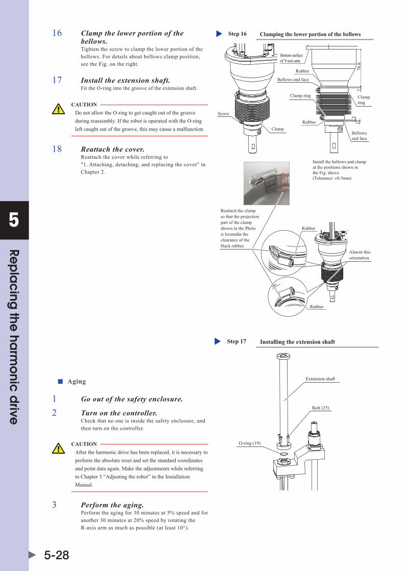
5
Rep
lac
ing the
harm
onic
drive
5-28
16 Clamp the lower portion of the bellows.Tighten the screw to clamp the lower portion of the bellows. For details about bellows clamp position, see the Fig. on the right.
76.6
22
1
Clamping the lower portion of the bellowsStep 16
Screw
Clamp
Rubber
Rubber
Almost this orientation
Reattach the clampso that the projectionpart of the clamp shown in the Photo is locatedin the clearance of theblack rubber.
Rubber
Bottom surface of Y-axis arm
Rubber
Bellows end face
Clamp ring
Bellows end face
Clamp ring
Install the bellows and clamp at the positions shown in the Fig. above.(Tolerance: ±0.5mm)
17 Install the extension shaft.Fit the O-ring into the groove of the extension shaft.
CAUTION Do not allow the O-ring to get caught out of the groove during reassembly. If the robot is operated with the O-ring left caught out of the groove, this may cause a malfunction.
18 Reattach the cover.Reattach the cover while referring to "1. Attaching, detaching, and replacing the cover" in Chapter 2.
■ Aging
1 Go out of the safety enclosure.
2 Turn on the controller.Check that no one is inside the safety enclosure, and then turn on the controller.
CAUTION After the harmonic drive has been replaced, it is necessary to perform the absolute reset and set the standard coordinates and point data again. Make the adjustments while referring to Chapter 3 “Adjusting the robot” in the Installation Manual.
3 Perform the aging.Performtheagingfor30minutesat5%speedandforanother30minutesat20%speedbyrotatingtheR-axis arm as much as possible (at least 10°).
Installing the extension shaftStep 17
O-ring (19)
Extension shaft
Bolt (25)

5
Rep
lac
ing the
harm
onic
drive
5-29
2.2 R6YXGP500, R6YXGP600, R6YXGHP600, R6YXGP700, R6YXGP800, R6YXGP900, R6YXGP1000
2.2.1 Replacing the X-axis harmonic drive
WARNING bEFoREsTaRTInGThEWoRK,ThoRoUGhLYREad“1.aTTaChInG,dETaChInG,andREPLaCInGThECovER”InChaPTER2.
The following shows the parts and tools necessary for the X-axis harmonic drive replacement work.
1. Replacement parts
• R6YXGP500,R6YXGP600
Part Name OMRON Part No. Part No. / Specs Q'ty Remarks
1 Harmonic drive KbF-m2110-000 1
2 O-ringCross section diameter: 1.30mm Inner diameter: 66.5mm
1 Supplied with harmonic drive
3 O-ring Kn4-m2143-000 s90(JIs) 1 Becomes worn and must be replaced
4 O-ring 90990-17J030Cross section diameter: 1.78mm Inner diameter: 66.4mm
1 Becomes worn and must be replaced
5 Motor mounting bolt
KbP-m259a-000 M6, length: 16 4Must be replaced when robot referencenumberispriortoKC346
91312-06016 M6, length: 16 4Spare parts for robots with a referencenumberofKC346orlater
6 Harmonic drive mounting bolt 91312-04020 M4, length: 20 16 Must be replaced
7 Harmonic drive mounting bolt 91312-04030 M4, length: 30 11 Must be replaced
8 Panhead bolt for dog 98502-04030 M4, length: 30 1 Spare parts
9 Nut for dog 95302-05600 M4 1 Spare parts
10 Washer 92903-04600 M4 16 Must be replaced
• R6YXGHP600,R6YXGP700,R6YXGP800,R6YXGP900,R6YXGP1000
Part Name OMRON Part No. Part No. / Specs Q'ty Remarks
1 Harmonic drive KbP-m2110-000 1
2 O-ringCross section diameter: 1.50mm Inner diameter: 87.5mm
1 Supplied with harmonic drive
3 O-ring Kn5-m2159-000 s115(JIs) 1 Becomes worn and must be replaced
4 O-ring 90990-17J035Cross section diameter: 1.50mm Inner diameter: 82.0mm
1 Becomes worn and must be replaced
5 Motor mounting bolt 91312-5016 M5, length: 16 4 Spare parts
6 Harmonic drive mounting bolt 91312-05040 M5, length: 40 16 Must be replaced
7 Harmonic drive mounting bolt 91312-05040 M5, length: 40 11 Must be replaced
8 Panhead bolt for dog 98502-05040 M5, length: 40 1 Spare parts
9 Nut for dog 95302-06600 M6 1 Spare parts
10 Washer KbF-m2146-001 1 Spare parts

5
Rep
lac
ing the
harm
onic
drive
5-30
2. Torque wrench, etc.
CAUTION Use accurately calibrated torque screwdrivers and torque wrenches.
• R6YXGP500,R6YXGP600
Name Part No. Manufacturer Remarks
A
Torque wrench n230qLK Kanon (Nakamura Mfg. Co., Ltd.)
For M6 hex socket head bolt Tightening torque: 15.2Nm (156kgfcm)
Drive bit 3Kh5L TonE (maedaKinzokuKogyo)
Attachment hexagonal width across flat: 9.53mm Overall length: 100mm Hexagonal width across flat at tip: 5mm
BTorque wrench n120qLK Kanon
(Nakamura Mfg. Co., Ltd.)For M4 hex socket head bolt Tightening torque: 4.0Nm (41kgfcm)
Drive bit 2H3 TonE (maedaKinzokuKogyo)
Attachment hexagonal width across flat: 6.35mm Hexagonal width across flat at tip: 3mm
C
Torque screwdriver n20LTdK Kanon (Nakamura Mfg. Co., Ltd.)
For M4 set screw Tightening torque: 1.7Nm (17kgfcm)
Drive bit 3C2010 NAC (Nagahori Industry Co., Ltd.)
Attachment hexagonal width across flat: 6.35mm Overall length: 100mm Hexagonal width across flat at tip: 2mm
D
Torque screwdriver n20LTdK Kanon (Nakamura Mfg. Co., Ltd.)
For M4 Phillips-head screw Tightening torque: 1.6Nm (16kgfcm)
Drive bit +2×50 vesselCo.,Inc.Attachment hexagonal width across flat: 6.35mm Overall length: 50mm Bit number: #2
• R6YXGHP600,R6YXGP700,R6YXGP800,R6YXGP900,R6YXGP1000
Name Part No. Manufacturer Remarks
A
Torque wrench n230qLK Kanon (Nakamura Mfg. Co., Ltd.)
For M5 hex socket head bolt Tightening torque: 9Nm (92kgfcm)
Drive bit BT3-04L KTC (KyotoTool)
Attachment hexagonal width across flat: 9.53mm Overall length: 128mm Hexagonal width across flat at tip: 4mm
B
Torque wrench n230qsPK Kanon (Nakamura Mfg. Co., Ltd.)
For M5 hex socket head bolt Tightening torque: 8.4Nm (86kgfcm)
Drive bit 3010M-100 Koken (YamashitaKogyoKenkyusho)
Attachment hexagonal width across flat: 9.53mm Overall length: 100mm Hexagonal width across flat at tip: 4mm
C
Torque screwdriver n20LTdK Kanon (Nakamura Mfg. Co., Ltd.)
For M4 set screw Tightening torque: 1.7Nm (17kgfcm)
Drive bit 3C2010 NAC (Nagahori Industry Co., Ltd.)
Attachment hexagonal width across flat: 6.35mm Overall length: 100mm Hexagonal width across flat at tip: 2mm
D
Torque screwdriver n50LTdK Kanon (Nakamura Mfg. Co., Ltd.)
For M5 Phillips-head screw Tightening torque: 3.2Nm (32kgfcm)
Drive bit B35+2×50 vesselCo.,Inc.Attachment hexagonal width across flat: 6.35mm Overall length: 50mm Bit number: #2
3. Other tools
Name Part No. Manufacturer Remarks
Harmonic grease 4B No.2 (*1) Harmonic Drive Systems Do not use grease if it was purchased 4 or more years ago. The grease has probably deteriorated.
Cleaning wipe
Phillips screwdriver
Hex wrench set
Screw thread locking agent Loctite 262 Henkel High strength type (red)
*1: R6YXGP500, R6YXGP600: 20g R6YXGHP600, R6YXGP700, R6YXGP800, R6YXGP900, R6YXGP1000: 60g

5
Rep
lac
ing the
harm
onic
drive
5-31
■ Removal
Follow the steps below to remove the X-axis parts.
1 Turn off the controller.
2 Place a sign indicating the robot is being adjusted.Place a sign indicating the robot is being adjusted, to keep others from operating the controller or operation panel.
3 Enter the safety enclosure.
CAUTION In the following steps, if the Y-axis arm is not removed from the X-axis arm, the integrated unit is very heavy. So, it is recommended to perform the work after the Y-axis arm has been removed from the X-axis arm beforehand while referring to "2.2.2. Replacing the Y-axis harmonic drive".
4 Remove the cover from the base.Remove the cover while referring to "1. Attaching, detaching, and replacing the cover" in Chapter 2.
Cover
Screw M4×8
Cover
The round terminal of the X-axis motor is present inside here. So, disconnect this terminal.
Removing the coverStep 4-5
5 Disconnect the connectors of the X-axis motor power wire XM and resolver wire XP in the base, and the round terminal of the X-axis motor.
CAUTION When removing the motor, pay special attention so that your hand is not caught in the potion between the motor and base.
NOTE • IntheR6YXGP500andR6YXGP600,ano-ringisfitted into the portion between the motor mating end face and the base. Be sure to replace this O-ring with a new one. • IntheR6YXGhP600,R6YXGP700,R6YXGP800, R6YXGP900andR6YXGP1000,ano-ringisfittedinto theportionbetweentheendfaceofthemotorflangeand the base. Be sure to replace this O-ring with a new one.
6 Remove the X-axis motor.1. Using the tool A, remove the bolts that secure the
motor. The bolts are replaced with new ones later on.
2. Support the motor so that it does not drop.
3. Pull out the motor from the plate while turning the X-axis arm.
Removing the X-axis motorStep 6
Bolt M6 (M5)Tool A X-axis motor
Base
* Values in parentheses apply to the R6YXGHP600, R6YXGP700, R6YXGP800, R6YXGP900 and R6YXGP1000.

5
Rep
lac
ing the
harm
onic
drive
5-32
7 Remove the wave generator from the motor shaft.Remove the set screw (1 pc.) that secure the wave generator. For the R6YXGHP600, R6YXGP700, R6YXGP800, R6YXGP900 and R6YXGP1000, further remove the spacer and bolt.
Removing the wave generatorStep 7
M4 set screw(Supplied with harmonic drive) Wave generator
(Harmonic drive)
Motor mating end faceDo not remove this spacer.
Motor flange end face
R6YXGP500, R6YXGP600
M4 set screw(Supplied with harmonic drive)
M5×16
Wave generator(Harmonic drive)
Spacer
Motor flange end face
R6YXGHP600, R6YXGP700, R6YXGP800, R6YXGP900, R6YXGP1000
CAUTION aspacerisfittedintotheportionbetweenthewavegeneratorand motor. Carefully handle it so that it is not lost. In the R6YXGHP600, R6YXGP700, R6YXGP800, R6YXGP900 and R6YXGP1000,thisspacerisnotfitted.
WARNING • IFThEX-aXIsaRmmoUnTInGboLTsaRE REmovEdInsTEP8,ThEX-aXIsaRmComEs OFF, CAUSING HAZARDOUS SITUATION. IFahEavYTooLIsaTTaChEdToThEaRmTIP, ThEaRmmaYdRoP.so,TaKEGREaTCaRE WhEnREmovInGThEX-aXIsaRmmoUnTInG boLTs.(sEEThEFIG.InsTEP8.) • IFThEX-aXIsaRmREmovaLWoRKIs PERFoRmEdaLonE,ThIsIsdanGERoUs. REmovEThEX-aXIsaRmbYTWooRmoRE PERsonnELoRREmovEThEY-aXIsaRm bEFoREhand.FoRdETaILsaboUThoWTo REmovEThEY-aXIsaRm,sEE "2.2.2.REPLaCInGThEY-aXIshaRmonIC dRIvE".
8 Remove the X-axis arm.Using the tool B, remove the bolts that secure the X-axis arm. Place the X-axis arm that has been removed in a place where it does not hinder the work.
Step 8 Removing the X-axis arm
BoltTool B
O-ringO-ring
R6YXGP500, R6YXGP600 R6YXGHP600, R6YXGP700, R6YXGP800, R6YXGP900,R6YXGP1000

5
Rep
lac
ing the
harm
onic
drive
5-33
9 Remove the X-axis harmonic drive from the X-axis arm.Remove the bolts, panhead bolts, and nuts that secure the X-axis harmonic drive.
Removing the harmonic driveStep 9
O-ring
Harmonic drive
O-ring supplied with harmonic drive
Bolt M4 (M5)
M5 nut (M6 nut)
Panhead boltM4 (M5)
* Values in parentheses apply to the R6YXGHP600, R6YXGP700, R6YXGP800, R6YXGP900 and R6YXGP1000.
NOTE ano-ringisfittedtotheX-axisarm.Replacethiso-ringwith a new one.
■ Replacement and reassembly
Follow the steps below to replace the harmonic drive with a new one and reassemble it.
1 Perform the work shown below before reassembling the harmonic drive.1. Apply the harmonic grease to new wave generator and flex spline. For details about how to apply the harmonic grease,
see the Fig. below. Before applying the grease, degrease the top and bottom surfaces of the harmonic drive.
Step 1 Applying the harmonic grease
Temporarily secured bolt
Degrease the installation surface.
Circular spline
* Values in parentheses apply to the R6YXGHP600, R6YXGP700, R6YXGP800, R6YXGP900 and R6YXGP1000.
Apply the grease to the gear clearances.
Apply grease to the entire inner surface.Amount of grease: 16.6g (56.2g)
Wave generator
Fill ball spaces with the grease sufficiently.Apply the grease to the entire surface of Oldham's coupling.Total grease amount: 3.4g (3.8g)
Degrease the installation surface.
Flex spline
2. Remove the old grease and worn-out particles from the motor, base, and X-axis arm completely.
CAUTION • Ifforeignmatteriscaughtinduringreassemblywork,thismaycausethenoisefromtheharmonicdriveortheharmonicdriveto break. • Never remove the temporarily secured bolts. Doing so may cause a misalignment.

5
Rep
lac
ing the
harm
onic
drive
5-34
2 Secure a new harmonic drive (1) to the X-axis arm.1. Degrease the harmonic drive installation surface
of the X-axis arm. Do not apply the grease to the seating part.
2. Fit the O-ring (3) coated with the new harmonic grease into the O-ring groove of the X-axis arm. Since the grease application to the O-ring is intended to prevent the O-ring from coming off, it is accepted to apply a small amount of the grease.
Mounting the harmonic driveStep 2, 4
New O-ring (3)
New harmonic drive (1)
Nut (9)
Make the bolt matched with the spot facing part of the arm.
O-ring groove
Degrease the harmonic drive mounting surface of the X-axis arm.* Do not apply the grease to the seating part.
Degrease the installation surfaces to the X-axis arm.
Panhead bolt (8) Tool DAssemble the panhead bolt at the same position as the X-axis arm during reassembly.
New bolt (7) Tool B
O-ring supplied with the harmonic drive
CAUTION Do not allow the O-ring to get caught out of the groove during reassembly. If the robot is operated with the O-ring left caught out of the groove, this may cause a malfunction.
3. Secure the new harmonic drive to the X-axis arm with new bolts. Apply harmonic grease 4B No.2 to the tip of each bolt so that the roots of at least the first four threads are filled with grease. Grease applied to the bolt tip is intended to stabilize the bolt axial force.
4. Secure the panhead bolts and nuts at their original positions.
Applying the grease to the mounting boltStep 2, 5
4B No.2 grease
CAUTION Do not apply the grease to the panhead bolt. Doing so may cause the bolt to loosen.
3 Tighten the bolts and panhead bolts in the order shown below.1. Using the wrench, tighten the bolts and panhead
bolts manually in the order indicated by circled numbers.
2. Using the torque wrench, tighten the bolts and panheadboltstoapproximately50%ofthespecified torque in the order indicated by circled numbers.
3. Tighten the bolts and panhead bolts to the specified torque in the order indicated by circled numbers. Then, loosen the bolts and panhead bolts 1 to 2 rotations once (do not remove any bolt at this time). After that, tighten the first bolt to the specified torque again, and then tighten the next and subsequent bolts to the specified torque in order. This work is intended to stabilize the bolt axial force.
4. Finally, check that the bolts and panhead bolts are tightened to the specified torque.
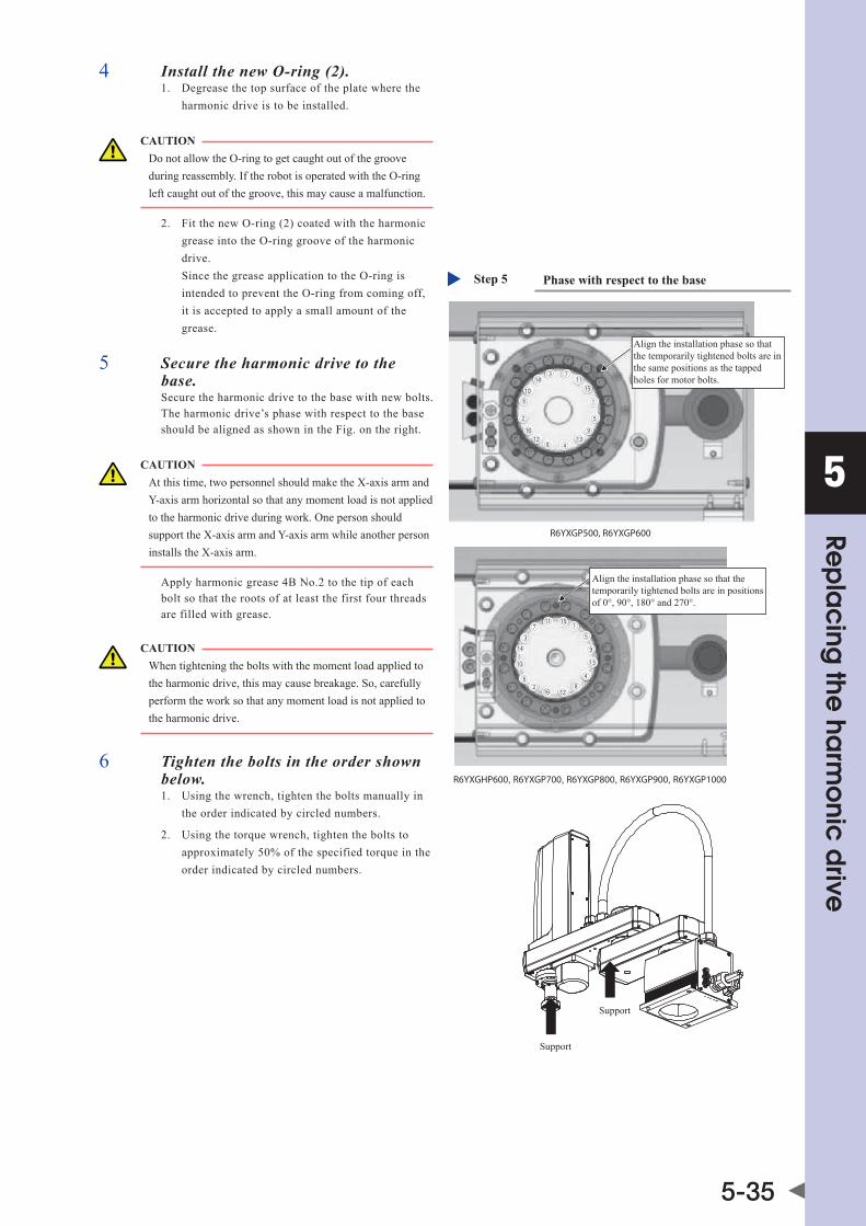
5
Rep
lac
ing the
harm
onic
drive
5-35
4 Install the new O-ring (2).1. Degrease the top surface of the plate where the
harmonic drive is to be installed.
CAUTION Do not allow the O-ring to get caught out of the groove during reassembly. If the robot is operated with the O-ring left caught out of the groove, this may cause a malfunction.
2. Fit the new O-ring (2) coated with the harmonic grease into the O-ring groove of the harmonic drive. Since the grease application to the O-ring is intended to prevent the O-ring from coming off, it is accepted to apply a small amount of the grease.
5 Secure the harmonic drive to the base.Secure the harmonic drive to the base with new bolts. The harmonic drive’s phase with respect to the base should be aligned as shown in the Fig. on the right.
Phase with respect to the baseStep 5
Align the installation phase so that the temporarily tightened bolts are in the same positions as the tapped holes for motor bolts.
Align the installation phase so that the temporarily tightened bolts are in positions of 0°, 90°, 180° and 270°.
Support
Support
R6YXGP500, R6YXGP600
R6YXGHP600, R6YXGP700, R6YXGP800, R6YXGP900, R6YXGP1000
CAUTION At this time, two personnel should make the X-axis arm and Y-axis arm horizontal so that any moment load is not applied to the harmonic drive during work. One person should support the X-axis arm and Y-axis arm while another person installs the X-axis arm.
Apply harmonic grease 4B No.2 to the tip of each bolt so that the roots of at least the first four threads are filled with grease.
CAUTION When tightening the bolts with the moment load applied to the harmonic drive, this may cause breakage. So, carefully perform the work so that any moment load is not applied to the harmonic drive.
6 Tighten the bolts in the order shown below.1. Using the wrench, tighten the bolts manually in
the order indicated by circled numbers.
2. Using the torque wrench, tighten the bolts to approximately50%ofthespecifiedtorqueintheorder indicated by circled numbers.

5
Rep
lac
ing the
harm
onic
drive
5-36
3. Tighten the bolts to the specified torque in the order indicated by circled numbers. Then, loosen the bolts 1 to 2 rotations once (do not remove any bolt at this time). After that, tighten the first bolt to the specified torque again, and then tighten the next and subsequent bolts to the specified torque in order.
4. Finally, check that the bolts are tightened to the specified torque.
7 Secure the spacer and wave generator.1. For the R6YXGHP600, R6YXGP700,
R6YXGP800, R6YXGP900 and R6YXGP1000, secure the wave generator with the spacer and M5 bolt.
2. Pass the spacer and wave generator through the motor shaft. Push in the spacer and wave generator until they are in contact with the motor.
3. Secure the wave generator with the set screw (1 pc.). At this time, apply a small amount of the screw lock to the set screw.
Securing the spacer and wave generatorStep 7
Wave generator (Harmonic drive)
Motor mating end face
Do not removethis spacer.
Motor flange end face
M4 set screw(Supplied with the harmonic drive.)Apply a small amount of the screw lock.Use the tool C.
M5×16 Tool A
M4 set screw(Supplied with the harmonic drive.)Apply a small amount of the screw lock.Use the tool C.
Wave generator (Harmonic drive)
Motor flange end face
Washer (10)
R6YXGP500, R6YXGP600
R6YXGHP600, R6YXGP700, R6YXGP800, R6YXGP900, R6YXGP1000
CAUTION • Ifitisdifficulttofitthewavegeneratorontothemotor shaft by pushing by hand, do not forcefully push in. Grind the key or motor shaft with sandpaper or similar tool to makeiteasiertofitthewavegeneratorontothemotor shaft. • applythespecifiedamountofharmonicgreasetoeach partoftheharmonicdrive.aninsufficientamountof grease may shorten the service life of the drive parts, and an excessive amount may cause the grease to leak.
8 Fit a new O-ring (4) into the base cylindrical surface and push it into the upper end face.For the R6YXGHP600, R6YXGP700, R6YXGP800, R6YXGP900 and R6YXGP1000, it is accepted to fit a new O-ring into one groove.
Installing the baseStep 6, 8
New bolt (7)Tool B
Temporarily tightened bolt
Do not apply grease to the mating flange.
Degrease the mating surface on top of the base where the harmonic drive is to be installed.
R6YXGP500, R6YXGP600 R6YXGHP600, R6YXGP700, R6YXGP800, R6YXGP900, R6YXGP1000
O-ring (4)O-ring (4)
CAUTION Do not allow the O-ring to get caught out of the groove during reassembly. If the robot is operated with the O-ring left caught out of the groove, this may cause a malfunction.

5
Rep
lac
ing the
harm
onic
drive
5-37
9 Secure the X-axis motor to the base.1. Push the X-axis motor into the plate while
moving the X-axis arm manually.
2. Using the tool A, uniformly tighten the four bolts while moving the X-axis arm by hand slowly left and right at intervals of 45°. At this time, if any jamming or catching is felt, reassemble from the beginning.
Installing the X-axis motorStep 9
New bolt (5)Tool A
Base
X-axis motor
10 Connect the connectors of the X-axis motor power wire XM and resolver wire XP, and the round terminal of the X-axis motor.
11 Reattach the base front and rear covers.
■ Aging
1 Go out of the safety enclosure.
2 Turn on the controller.Check that no one is inside the safety enclosure, and then turn on the controller.
CAUTION After the harmonic drive has been replaced, it is necessary to perform the absolute reset and set the standard coordinates and point data again. Make the adjustments while referring to Chapter 3 “Adjusting the robot” in the Installation Manual.
3 Perform the aging.Performtheagingfor30minutesat5%speedandforanother30minutesat20%speedbyrotatingtheX-axisarmasmuchas possible (at least 10°).
Reattaching the coverStep 10-11
Cover
Cover
Screw M4×8
The round terminal of the X-axis motor is present inside here. So, connect this terminal.

5
Rep
lac
ing the
harm
onic
drive
5-38
2.2.2 Replacing the Y-axis harmonic drive
WARNING bEFoREsTaRTInGThEWoRK,ThoRoUGhLYREad“1.aTTaChInG,dETaChInG,andREPLaCInGThECovER”InChaPTER2.
The coil tube shown below is absolutely required for the Y-axis reduction unit replacement work. If the coil tube has notbeenconnected,prepareanewcoiltube.Evenwhenthecoiltubehasbeenconnected,prepareanewcoiltubesinceit needs to be replaced.If the coil tube is not connected, this may cause the grease to leak.
Coil tube
Coil tube
The following shows the parts and tools necessary for the Y-axis harmonic drive replacement work.
1. Replacement parts
• R6YXGP500,R6YXGP600
Part Name OMRON Part No. Part No. / Specs Q'ty Remarks
1 Harmonic drive KbF-m2510-000 1
2 O-ring Cross section diameter: 0.99mm Inner diameter: 53.28mm 1 Supplied with harmonic drive
3 O-ring Kn4-m257K-000 Cross section diameter: 1.78mm Inner diameter: 72.75mm 1 Becomes worn and must be replaced
4 O-ring Kn3-m2143-000 Cross section diameter: 1.50mm Inner diameter: 49.00mm 1 Becomes worn and must be replaced
5 Motor mounting boltKbF-m259a-000 M5, length: 12 4 Must be replaced when robot
referencenumberispriortoKC394
91312-05012 M5, length: 12 4 Spare parts for robots with a referencenumberofKC394orlater
6 Harmonic drive mounting bolt 91312-03016 M3, length: 16 16 Must be replaced
7 Harmonic drive mounting bolt 91312-03030 M3, length: 30 11 Must be replaced
8 Panhead bolt for dog 98502-03030 M3, length: 30 1 Spare parts
9 Nut for dog 95302-04600 M4 1 Spare parts
10 Coil tube KbF-m2511-000 1
11 Joint $UEF4-m3 UEF4-m3(KoGanEI) 1 No need to be replaced if coil tube is originally equipped

5
Rep
lac
ing the
harm
onic
drive
5-39
• R6YXGHP600,R6YXGP700,R6YXGP800,R6YXGP900,R6YXGP1000
Part Name OMRON Part No. Part No. / Specs Q'ty Remarks
1 Harmonic drive KbP-m2510-000 1
2 O-ringCross section diameter: 1.30mm Inner diameter: 66.5mm
1 Supplied with harmonic drive
3 O-ring Kn4-m2143-000 s90(JIs) 1 Becomes worn and must be replaced
4 O-ring 90990-17J030Cross section diameter: 1.78mm Inner diameter: 66.4mm
1 Becomes worn and must be replaced
5 Motor mounting bolt
KbP-m259a-000 M6, length: 16 4Must be replaced when robot referencenumberispriortoKC346
91312-06016 M6, length: 16 4Spare parts for robots with a referencenumberofKC346orlater
6 Harmonic drive mounting bolt 91312-04020 M4, length: 20 16 Must be replaced
7 Harmonic drive mounting bolt 91312-04030 M4, length: 30 11 Must be replaced
8 Panhead bolt for dog 98502-04030 M4, length: 30 1 Spare parts
9 Nut for dog 95302-05600 M4 1 Spare parts
10 Washer 92903-04600 M4 16 Must be replaced
11 Coil tube KbP-m2511-000 1
12 Joint $UEF4-m3 UEF4-m3(KoGanEI) 1No need to be replaced if coil tube is originally equipped
13 Washer KbF-m2146-001 1 Spare parts
2. Torque wrench, etc.
CAUTION Use accurately calibrated torque screwdrivers and torque wrenches.
• R6YXGP500,R6YXGP600
Name Part No. Manufacturer Remarks
A
Torque wrench n120sPCKKanon (Nakamura Mfg. Co., Ltd.)
For M5 hex socket head bolt Tightening torque: 7.4Nm (76kgfcm)
Changeable head 230hCK4Kanon (Nakamura Mfg. Co., Ltd.)
Wrench (without ball end) for M5 hex socket head bolt; insert 110mm
B
Torque screwdriver n30LTdKKanon (Nakamura Mfg. Co., Ltd.)
For M3 hex socket head bolt Tightening torque: 1.8Nm (18kgfcm)
Drive bitB35, opposite side 2.5×75
vesselCo.,Inc.Attachment hexagonal width across flat: 6.35mm Overall length: 75mm Hexagonal width across flat at tip: 2.5mm
C
Torque screwdriver n12LTdKKanon (Nakamura Mfg. Co., Ltd.)
For M3 set screw Tightening torque: 0.7Nm (7kgfcm)
Drive bit 3C1507NAC (Nagahori Industry Co., Ltd.)
Attachment hexagonal width across flat: 6.35mm Overall length: 70mm Hexagonal width across flat at tip: 1.5mm
D
Torque screwdriver n12LTdKKanon (Nakamura Mfg. Co., Ltd.)
For M3 Phillips-head screw Tightening torque: 0.9Nm (9kgfcm)
Drive bit B35+2×50 vesselCo.,Inc.Attachment hexagonal width across flat: 6.35mm Overall length: 50mm Bit number: #2

5
Rep
lac
ing the
harm
onic
drive
5-40
• R6YXGHP600,R6YXGP700,R6YXGP800,R6YXGP900,R6YXGP1000
Name Part No. Manufacturer Remarks
ATorque wrench n230sPCK Kanon
(Nakamura Mfg. Co., Ltd.)For M6 hex socket head bolt Tightening torque: 15.2Nm (156kgfcm)
Changeable head 230hCK5 Kanon (Nakamura Mfg. Co., Ltd.)
Wrench (without ball end) for M6 hex socket head bolt; insert 100mm
B
Torque screwdriver n50LTdK Kanon (Nakamura Mfg. Co., Ltd.)
For M4 hex socket head bolt Tightening torque: 4.0Nm (41kgfcm)
Drive bit 3C3007 NAC (Nagahori Industry Co., Ltd.)
Attachment hexagonal width across flat: 6.35mm Overall length: 70mm Hexagonal width across flat at tip: 3mm
C
Torque screwdriver n20LTdK Kanon (Nakamura Mfg. Co., Ltd.)
For M4 set screw Tightening torque: 1.7Nm (17kgfcm)
Drive bit 3C2010 NAC (Nagahori Industry Co., Ltd.)
Attachment hexagonal width across flat: 6.35mm Overall length: 100mm Hexagonal width across flat at tip: 2mm
D
Torque screwdriver n20LTdK Kanon (Nakamura Mfg. Co., Ltd.)
For M4 Phillips-head screw Tightening torque: 1.6Nm (16kgfcm)
Drive bit +2×50 vesselCo.,Inc.Attachment hexagonal width across flat: 6.35mm Overall length: 50mm Bit number: #2
3. Other tools
Name Part No. Manufacturer Remarks
Harmonic grease 4B No.2 (*1) Harmonic Drive Systems Do not use grease if it was purchased 4 or more years ago. The grease has probably deteriorated.
Cleaning wipe
Phillips screwdriver
Hex wrench set
Screw thread locking agent Loctite 262 Henkel High strength type (red)
Spanner (wrench) width across flat: 5mm
Tie band
*1: R6YXGP500, R6YXGP600: 27g R6YXGHP600, R6YXGP700, R6YXGP800, R6YXGP900, R6YXGP1000: 48g Make sure to install a coil tube for applying the specified amount of grease. If a coil tube is not used, grease may leak.

5
Rep
lac
ing the
harm
onic
drive
5-41
■ Removal
Follow the steps below to remove the Y-axis parts.
1 Turn off the controller.
2 Place a sign indicating the robot is being adjusted.Place a sign indicating the robot is being adjusted, to keep others from operating the controller or operation panel.
3 Enter the safety enclosure.
4 Remove the cover.Remove the cover while referring to "1. Attaching, detaching, and replacing the cover" in Chapter 2.
Removing the coverStep 4-5
Screw M3×8
Cover
Unplug the YM and YP connectors in the Y-axis arm.Also disconnect the Y-axisring-tongue terminal.
Cover
Screw M4×105 Disconnect the connectors of the
Y-axis motor power wire YM and resolver wire YP in the Y-axis arm, and the round terminal of the Y-axis motor.
6 Remove the cover.Remove the cover while referring to "1. Attaching, detaching, and replacing the cover" in Chapter 2.
Disconnecting the jointStep 6-7
Opening
Coil tube
Cover
Cover
Tie band
Joint
7 Disconnect the coil tube or air tube.When the coil tube is connected, disconnect it from the joint. Cut the tie bands and take out the coil tube from the Y-axis arm window. If the coil tube is not connected, disconnect the air tube together with the joint. At this time, pay special attention so that no grease leaks from the tube and joint. For the wall-mount inverse model not needing the coil tube, move to Step 8. The work stated in Step 7 is not needed.
8 Remove the Y-axis motor.1. Remove the bolts that secure the Y-axis motor.
The bolts are replaced with new ones later on.
2. Gradually pull out the Y-axis motor while turning the Y-axis joint area.
3. Remove the O-ring.
Removing the Y-axis motorStep 8
Bolt M5Motor
O-ring
Bolt M6
O-ring
R6YXGP500, R6YXGP600
R6YXGHP600, R6YXGP700, R6YXGP800, R6YXGP900, R6YXGP1000
NOTE The O-ring of the Y-axis arm is replaced with a new one later on.

5
Rep
lac
ing the
harm
onic
drive
5-42
9 Remove the wave generator from the motor shaft.Remove the set screws (1 pcs.) that secure the wave generator.
Removing the wave generatorStep 9
Wave generatorM3 set screw
Key Motor shaft
Wave generator
Motor shaft
Spacer
M4 set screw
Key
R6YXGP500, R6YXGP600
R6YXGHP600, R6YXGP700, R6YXGP800, R6YXGP900, R6YXGP1000
WARNING IFThEY-aXIsmoUnTInGboLTsaREREmovEdInsTEP10,ThEY-aXIsaRmComEsoFF,CaUsInGHAZARDOUS SITUATION. IFahEavYTooLIsaTTaChEdToThEaRmTIP,ThEaRmmaYdRoP.so,TaKEGREaTCaREWhEnREmovInGThEX-aXIsaRmmoUnTInGboLTs.(sEEThEFIG.InsTEP10.)
10 Remove the Y-axis arm.1. Before removing the Y-axis arm, reattach the
cover so that the wiring is not stretched.
2. Remove the Y-axis arm mounting bolts.
3. Remove the Y-axis arm. Place the Y-axis arm that has been removed in a place where it is not in contact with the harness and it does not hinder the work.
4. Remove the O-ring. The O-ring of the harmonic drive is replaced with a new one later on. The O-ring may adhere to the bottom surface of the Y-axis arm. So, be sure to remove it completely.
Removing the Y-axis armStep 10
Y-axis arm
Bolt M3
O-ring
Cover
Screw
Harness
R6YXGP500, R6YXGP600
R6YXGHP600, R6YXGP700, R6YXGP800, R6YXGP900, R6YXGP1000
O-ringWasher
Bolt M4Cover

5
Rep
lac
ing the
harm
onic
drive
5-43
11 Remove the Y-axis harmonic drive from the top surface of the X-axis arm.1. Remove the bolts, panhead bolts, and nuts that
secure the Y-axis harmonic drive.
2. Remove the O-ring.
Removing the Y-axis harmonic driveStep 11
O-ring
Bolt M3 (M4)
Nut
Panhead bolt
X-axis arm
Harmonic driveNOTE The O-ring in the harmonic drive must be replaced with a new one later on.
■ Replacement and reassembly
Follow the steps below to replace the harmonic drive with a new one and reassemble it.
1 Perform the work shown below before reassembling the harmonic drive.1. Apply harmonic grease 4B No.2 to the wave generator and main body bottom of a new harmonic drive.
For details about how to apply the grease, see the Fig. below.
Step 1 Applying the harmonic grease
Fill ball spaces with the grease sufficiently.Apply the grease to the entire surface of Oldham's coupling.Total grease amount: 3g (3.4g)
Apply grease to the bottom evenly.Amount of grease: 24g (44.6g)
Temporarily tightened bolt
Degrease the bottom of the installation surface.
Degrease the installation surface.
* Values in parentheses apply to the R6YXGHP600, R6YXGP700, R6YXGP800, R6YXGP900 and R6YXGP1000.
Apply the grease to the gear clearances.
2. Remove the old grease and worn-out particles from the motor, X-axis arm, and Y-axis arm completely.
CAUTION • Ifforeignmatteriscaughtinduringreassemblywork,thismaycausethenoisefromtheharmonicdriveortheharmonicdriveto break. • neverremovethetemporarilysecuredbolts.doingsomaycauseamisalignment.
3. Apply the specified amount of harmonic grease to each part of the harmonic drive.
CAUTION aninsufficientamountofgreasemayshortentheservicelifeofthedriveparts,andanexcessiveamountmaycausethegreasetoleak.

5
Rep
lac
ing the
harm
onic
drive
5-44
2 Secure a new harmonic drive (1) to the X-axis arm.1. Degrease the harmonic drive installation surface
of the X-axis arm. Do not apply the grease to the seating surface.
2. Fit a new O-ring (3) into the O-ring groove in the X-axis arm.
Securing the harmonic driveStep 2-4
New O-ring (3)
New harmonic drive (1)
O-ring groove
New bolt (7), Tool B Nut (9)
Assemble the nut at the same position as the X-axis arm during reassembly.
Panhead bolt (8), Tool D
X-axis arm
Make the bolt matched with the spot facing position of the arm.Degrease the X-axis arm
mating surface where the harmonic drive is to be installed.Do not apply grease to the mating flange.
O-ring supplied with harmonic drive
CAUTION Do not allow the O-ring to get caught out of the groove during reassembly. If the robot is operated with the O-ring left caught out of the groove, this may cause a malfunction.
3. Place the new harmonic drive on the X-axis arm and secure it with the bolts. Apply harmonic grease 4B No.2 to the tip of each bolt so that the roots of at least the first four threads are filled with grease. Grease applied to the bolt tip is intended to stabilize the bolt axial force.
4. Secure the panhead bolts and nuts at their original positions.
Applying the grease to the mounting boltStep 2, 5
4B No.2 greaseCAUTION Do not apply the grease to the panhead bolt. Doing so may cause the bolt to loosen.
3 Tighten the bolts and panhead bolts in the order shown below.1. Using the wrench, tighten the bolts and panhead
bolts manually in the order indicated by circled numbers.
2. Using the torque driver, tighten the bolts and panheadboltstoapproximately50%ofthespecified torque in the order indicated by circled numbers.
3. Tighten the bolts and panhead bolts to the specified torque in the order indicated by circled numbers.
4. Finally, check that the bolts and panhead bolts are tightened to the specified torque.
Bolt and panhead bolt tightening orderStep 3

5
Rep
lac
ing the
harm
onic
drive
5-45
4 Install the O-ring (2) provided with the new harmonic drive.1. Degrease the installation surface on the top
surface of the harmonic drive.
2. Fit the O-ring supplied with the new harmonic drive into the O-ring groove of the harmonic drive. If it is difficult to fit the O-ring into the groove, slightly stretch the O-ring. It is accepted to apply a small amount of the harmonic drive grease to the O-ring in order to prevent the O-ring from coming off the groove.
CAUTION Do not allow the O-ring to get caught out of the groove during reassembly. If the robot is operated with the O-ring left caught out of the groove, this may cause a malfunction.
5 Secure the Y-axis arm to the harmonic drive.1. Degrease the Y-axis arm side where the harmonic
drive is to be installed.
2. Apply harmonic grease 4B No.2 to the tip of each bolt so that the roots of at least the first four threads are filled with grease.
CAUTION When tightening the bolts with the moment load applied to the harmonic drive, this may cause breakage. Perform the work not to apply the moment load to the harmonic drive.
3. Align the harmonic drive’s phase with respect to the Y-axis arm and install the Y-axis arm so that the spot facing of the harmonic drive is matched with the tapped hole in the Y-axis arm. At this time, two work personnel perform the work with the Y-axis arm kept horizontally so that no moment load is applied to the Y-axis harmonic drive. One person supports the end of the Y-axis arm and the other person secures the Y-axis arm in place.
Installing the Y-axis armStep 5-6
Y-axis armNew bolt (6), Tool B
Do not apply the grease to the seating part.
Degrease the Y-axismating surfacewhere the harmonicdrive is to be installed.
New bolt (6), Tool B
Do not apply the grease to the seating part.
Degrease the Y-axismating surfacewhere the harmonicdrive is to be installed.
New washer (10)
R6YXGP500, R6YXGP600
R6YXGHP600, R6YXGP700, R6YXGP800, R6YXGP900, R6YXGP1000
Securing the Y-axis armStep 5
Support
Counterboring in harmonic drive
Tapped holein Y-axis arm

5
Rep
lac
ing the
harm
onic
drive
5-46
6 Tighten the bolts in the order shown below.1. Using the wrench, tighten the bolts manually in
the order indicated by circled numbers.
2. Using the torque driver, tighten the bolts to approximately50%ofthespecifiedtorqueintheorder indicated by circled numbers.
3. Tighten the bolts to the specified torque in the order indicated by circled numbers.
4. Finally, check that the bolts are tightened to the specified torque.
Bolt tightening orderStep 6
Adjust the phase so that the temporarily secured bolt and motor bolt tapped hole are located at the same position.
R6YXGP500, R6YXGP600Step 6
Apply grease to fill in around this groove.
NOTE FortheR6YXGP500andR6YXGP600,applygreasetofillin around the groove.
7 Secure the wave generator.1. For the R6YXGHP600, R6YXGP700,
R6YXGP800, R6YXGP900 and R6YXGP1000, put a spacer and pass the wave generator through the motor shaft while carefully checking the orientation of the wave generator. At this time, push the wave generator until it is in contact with the stepped surface.
2. Secure the wave generator with the set screw (1 pc.). At this time, apply a small amount of the screw lock to the set screw. Securing the wave generatorStep 7
Motor
Apply small amount ofScrew Lock to the setscrew (supplied).Tightening torqueTool C
Motor shaft
Wave generator
Stepped surface
Motor
Apply small amount ofScrew Lock to the setscrew (supplied).Tightening torqueTool C
Motor shaft
Return washer (13) to its original position.
Wave generator
Stepped surface
R6YXGP500, R6YXGP600
R6YXGHP600, R6YXGP700, R6YXGP800, R6YXGP900, R6YXGP1000
CAUTION • Ifitisdifficulttofitthewavegeneratorontothemotor shaft by pushing by hand, do not forcefully push in. Grind the key or motor shaft with sandpaper or similar tool to makeiteasiertofitthewavegeneratorontothemotor shaft. • applythespecifiedamountofharmonicgreasetoeach partoftheharmonicdrive.aninsufficientamountof grease may shorten the service life of the drive parts, and an excessive amount may cause the grease to leak.

5
Rep
lac
ing the
harm
onic
drive
5-47
8 Subsequently, proceed the steps as follows.If the coil tube has already been connected, move to step 9. If the coil tube has not been connected, move to step 13. For the wall-mount inverse model not needing the coil tube, move to Step 9.
9 Secure the motor to the Y-axis arm temporarily.1. Open the cover. Pass the wiring through the
Y-axis arm side.
2. Fit a new O-ring (4) into the motor mating (Y-axis arm mating for the R6YXGHP600, R6YXGP700, R6YXGP800, R6YXGP900 and R6YXGP1000).
3. Gradually put the motor into the Y-axis arm while turning the Y-axis joint area and secure the motor to the Y-axis arm temporarily with the mounting bolts.
Securing the motor temporarilyStep 9-10
Motor
New O-ring (4)
New bolt (5),Tool A
New bolt (5),Tool A
New O-ring (4)
R6YXGP500, R6YXGP600
R6YXGHP600, R6YXGP700, R6YXGP800, R6YXGP900, R6YXGP1000
CAUTION Do not allow the O-ring to get caught out of the groove. If the robot is operated with the O-ring left caught out of the groove, this may cause a malfunction.
10 Retighten the temporarily secured bolts uniformly.Retighten the temporarily secured bolts (4 pcs.) uniformly while turning the Y-axis joint area. At this time, if unusual feeling such as jamming is felt, reassemble from the beginning.
12 Insert the coil tube.Insert the coil tube through the clearance between the Y-axis arm window and Y-axis. Connect the coil tube with the short straight portion to the joint. If the straight portion of the coil tube is too long, cut it to an appropriate level, and then connect it to the joint correctly. Connect the coil tube with the long straight portion to the Z-axis motor with tie bands. At this time, pay special attention so that the coil tube is not crushed or bent. If the straight portion of the coil tube is longer than the Z-axis motor, cut the excess part.
Inserting the coil tubeStep 11
Opening
Coil tube
Cover
Cover
Z-axis motor
Tie band
Joint
13 Install the cover.
14 Connect the connectors of the Y-axis motor power wire YM and resolver wire YP, and the round terminal of the Y-axis motor.

5
Rep
lac
ing the
harm
onic
drive
5-48
15 Reattach the cover. Reattaching the coverStep 14
Seal (R6YXGP500, R6YXGP600)KDN-M130A-000
SealKDP-M1329-000
Seal (R6YXGHP600, R6YXGP700, R6YXGP800, R6YXGP900, R6YXGP1000)KDP-M130A-000
■ Aging
1 Go out of the safety enclosure.
2 Turn on the controller.Check that no one is inside the safety enclosure, and then turn on the controller.
CAUTION After the harmonic drive has been replaced, it is necessary to perform the absolute reset and set the standard coordinates and point data again.
3 Perform the aging.Performtheagingfor30minutesat5%speedandforanother30minutesat20%speedbyrotatingtheY-axisarmasmuchas possible (at least 10°).

5
Rep
lac
ing the
harm
onic
drive
5-49
2.2.3 Replacing the R-axis harmonic drive
WARNING bEFoREsTaRTInGThEWoRK,ThoRoUGhLYREad“1.aTTaChInG,dETaChInG,andREPLaCInGThECovER”InChaPTER2.
The following shows the parts and tools necessary for the R-axis harmonic drive replacement work.
CAUTION At Step 2 of the "■ Replacement and reassembly" procedure, a motor-securing vise and a dial gauge are required in order to check the deflectionoftheharmonicdrive'swavegenerator. If a vise and dial gauge are not available, the wave generator can be installed at OMRON, with the assembly then being shipped to the customer. In that case, the customer should order one of the following "additional new motor" replacement parts and request that the wave generator be installed in the motor. Additional motors: KbF-m4883-002(R6YXGP500,R6YXGP600) KbP-m4883-001(R6YXGhP600,R6YXGP700,R6YXGP800,R6YXGP900,R6YXGP1000)
1. Replacement parts
• R6YXGP500,R6YXGP600
Part Name OMRON Part No. Part No. / Specs Q'ty Remarks
1 Harmonic drive KbF-m1821-100 1
2 O-ring Cross section diameter: 0.80mm Inner diameter: 45.40mm 1 Supplied with harmonic drive
3 O-ring Kn4-m1896-000 Cross section diameter: 1.78mm Inner diameter: 63.22mm 1 Becomes worn and must be replaced
4 O-ring 90990-17J031 Cross section diameter: 1.00mm Inner diameter: 35.30mm 1 Becomes worn and must be replaced
5 O-ring 90990-17J032 Cross section diameter: 1.00mm Inner diameter: 46.00mm 1 Becomes worn and must be replaced
6 O-ring 90990-17J034 Cross section diameter: 0.60mm Inner diameter: 22.20mm 1 Becomes worn and must be replaced
7 Motor mounting boltKbF-m259a-000 M5, length: 12 4 Must be replaced when robot reference
numberispriortoKC368
91312-05014 M5, length: 14 4 Spare parts for robots with a reference numberofKC368orlater
8 Harmonic drive mounting bolt 91312-03014 M3, length: 14 16 Must be replaced
9 Harmonic drive mounting bolt 91312-03025 M3, length: 25 11 Must be replaced
10 Panhead bolt for dog 98502-03030 M3, length: 30 1 Spare parts
11 Nut for dog 95302-04600 M4 1 Spare parts
13 Spline nut securing bolts 91312-04010 M4, length: 10 6 Spare parts
14 Endfaceseal(*1) KbF-m1886-000 1Replace with spare when damaged or missing.
15 Bearing nut 90185-03J00 1 Spare parts
16 Bearing 90933-01J003 6003ZZ 2 Spare parts
17 Bearing plate securing bolts 91312-05014 M5, length: 14 4 Spare parts
*1: A new end face seal will be subjected to a high level of friction if sufficient R-axis aging has not occurred. Therefore, be sure to perform R-axis aging, and do not replace this seal unless it is damaged.
• R6YXGHP600,R6YXGP700,R6YXGP800,R6YXGP900,R6YXGP1000
Part Name OMRON Part No. Part No. / Specs Q'ty Remarks
1 Harmonic drive KbP-m1821-011 1
2 O-ring Cross section diameter: 0.99mm Inner diameter: 53.28mm 1 Supplied with harmonic drive
3 O-ring Kn3-m2159-000 s71(JIs) 1 Becomes worn and must be replaced
4 O-ring 90990-17J036 Cross section diameter: 1.00mm Inner diameter: 43.00mm 1 Becomes worn and must be replaced

5
Rep
lac
ing the
harm
onic
drive
5-50
Part Name OMRON Part No. Part No. / Specs Q'ty Remarks
5 O-ring 90990-17J038 Cross section diameter: 1.30mm Inner diameter: 53.00mm 1 Becomes worn and must be replaced
6 O-ring 90990-17J037 Cross section diameter: 0.50mm Inner diameter: 28.00mm 1 Becomes worn and must be replaced
7 Endfaceseal KbP-m1886-000 v-28a(n+C) 1
8 Motor mounting boltKbP-m259a-000 M6, length: 16 4 Must be replaced when robot reference
numberispriortoKC172
91312-06016 M6, length: 16 4 Spare parts for robots with a reference numberofKC172orlater
9 Harmonic drive mounting bolt 91312-03016 M3, length: 16 16 Must be replaced
10 Harmonic drive mounting bolt 91312-03025 M3, length: 25 11 Must be replaced
11 Bolt for dog 91312-03030 M3, length: 30 1 Spare parts
12 Dog KbP-m1888-000 1 Spare parts
13 Spline nut securing bolts 91312-05014 M5, length: 14 6 Spare parts
14 Endfaceseal(*1) KbP-m1886-000 1 Spare parts
15 Bearing nut KbP-m1862-000 1 Spare parts
16 Bearing 90933-01J022 6022ZZ 2 Spare parts
17 Bearing plate securing bolts 91312-05014 M5, length: 14 4 Spare parts
*1: A new end face seal will be subjected to a high level of friction if sufficient R-axis aging has not occurred. Therefore, be sure to perform R-axis aging, and do not replace this seal unless it is damaged.
2. Torque wrench, etc.
CAUTION Use accurately calibrated torque screwdrivers and torque wrenches.
• R6YXGP500,R6YXGP600
Name Part No. Manufacturer Remarks
ATorque wrench n120CPCK Kanon
(Nakamura Mfg. Co., Ltd.)For M5 hex socket head bolt Tightening torque: 7.4Nm (76kgfcm)
Changeable head 230hCK4 Kanon (Nakamura Mfg. Co., Ltd.)
Wrench (without ball end) for M5 hex socket head bolt; insert 110mm
B
Torque screwdriver n30LTdK Kanon (Nakamura Mfg. Co., Ltd.)
For M3 hex socket head bolt Tightening torque: 1.8Nm (18kgfcm)
Drive bit B35, opposite side 2.5×75 vesselCo.,Inc.
Attachment hexagonal width across flat: 6.35mm Overall length: 75mm Hexagonal width across flat at tip: 2.5mm
C
Torque screwdriver n20LTdK Kanon (Nakamura Mfg. Co., Ltd.)
For M4 set screw Tightening torque: 0.7Nm (7.1kgfcm)
Drive bit 3C2010 NAC (Nagahori Industry Co., Ltd.)
Attachment hexagonal width across flat: 6.35mm Overall length: 100mm Hexagonal width across flat at tip: 2mm
D
Torque screwdriver n12LTdK Kanon (Nakamura Mfg. Co., Ltd.)
For M3 Phillips-head screw Tightening torque: 0.9Nm (9kgfcm)
Drive bit B35+2×50 vesselCo.,Inc.Attachment hexagonal width across flat: 6.35mm Overall length: 50mm Bit number: #2
ERatchet handle FUTR-3/8 Fuji Seimitsu Insertion angle, 9.52 mm
Socket FUT#03 Fuji Seimitsu Socket for fine U-nut, M17 x P1.0
• R6YXGHP600,R6YXGP700,R6YXGP800,R6YXGP900,R6YXGP1000
Name Part No. Manufacturer Remarks
ATorque wrench n230sPCK Kanon
(Nakamura Mfg. Co., Ltd.)For M6 hex socket head bolt Tightening torque: 15.2Nm (156kgfcm)
Changeable head 230hCK5 Kanon (Nakamura Mfg. Co., Ltd.)
Wrench (without ball end) for M6 hex socket head bolt; insert 100mm
B
Torque screwdriver n30LTdK Kanon (Nakamura Mfg. Co., Ltd.)
For M3 hex socket head bolt Tightening torque: 1.8Nm (18kgfcm)
Drive bit B35, opposite side 2.5×75 vesselCo.,Inc.
Attachment hexagonal width across flat: 6.35mm Overall length: 75mm Hexagonal width across flat at tip: 2.5mm

5
Rep
lac
ing the
harm
onic
drive
5-51
C
Torque screwdriver n12LTdK Kanon (Nakamura Mfg. Co., Ltd.)
For M4 set screw Tightening torque: 0.8Nm (8.1kgfcm)
Drive bit 3C2010 NAC (Nagahori Industry Co., Ltd.)
Attachment hexagonal width across flat: 6.35mm Overall length: 100mm Hexagonal width across flat at tip: 2mm
3. Other tools
Name Part No. Manufacturer Remarks
Harmonic grease 4B No.2 (*1) Harmonic Drive Systems Do not use grease if it was purchased 4 or more years ago. The grease has probably deteriorated.
Cleaning wipe
Phillips screwdriver
Hex wrench set
19mm spanner R6YXGP500, R6YXGP600
Hook spannerFine U-nut outer diameter: 28mm
R6YXGP500, R6YXGP600
24mm spannerR6YXGHP600, R6YXGP700, R6YXGP800, R6YXGP900, R6YXGP1000
32mm spanner
Screw thread locking agent Loctite 262 Henkel High strength type (red)
*1: R6YXGP500, R6YXGP600: 8g R6YXGHP600, R6YXGP700, R6YXGP800, R6YXGP900, R6YXGP1000: 10g
■ Removal
Follow the steps below to remove the R-axis parts.
1 Turn off the controller.
2 Place a sign indicating the robot is being adjusted.Place a sign indicating the robot is being adjusted, to keep others from operating the controller or operation panel.
3 Enter the safety enclosure.
4 Remove the cover.Remove the cover while referring to "1. Attaching, detaching, and replacing the cover" in Chapter 2.
Removing the coverStep 4-5
Cover
Button bolt M3×8
Bolt M3×20 (M3×16)
Disconnect the R-axis motor ring-tongue terminal located inside the cover.
Cover
* Values in parentheses apply to the R6YXGHP600, R6YXGP700, R6YXGP800, R6YXGP900 and R6YXGP1000.
5 Disconnect the connectors of the R-axis motor power wire RM and resolver wire RP in the Y-axis arm, and the round terminal of the R-axis motor.
WARNING IFThEbEaRInGmoUnTInGboLTsaREREmovEdInsTEP6,ThEY-aXIsmaYdRoP,CaUsInGhazaRdoUssITUaTIon.bEFoREREmovInGThEbEaRInGmoUnTInGboLTs,sUPPoRTThEz-aXIsUsInGabasE,ETC.
6 Remove the bracket.
Removing the bracketStep 6
M4x35
SealKDN-M1568-000
SealKAD-M22KB-100

5
Rep
lac
ing the
harm
onic
drive
5-52
7 Remove the tool flange.After removing the positioning bolt, loosen the M6 bolts, then remove the tool flange in the downward direction.
Removing the tool flangeStep 7
Damper
M6 bolt Positioning bolt
Seal washer90990-36J006
8 Remove the holder.Loosen the 2 M4 set screws, then remove the holder in the downward direction.
9 Remove the bellows and the holder.After removing the bellows, replace the bellows O-ring. Also replace the holder O-ring after removing the holder.
Removing the holderStep 8
M4 set screws
Removing the bellows and holderStep 9
Holder
Bolt M3×8 SUS
Bellows O-ring90200-01J600
Bellows O-ring90200-01J750
Bellows O-ring90990-17J069 (R6YXGP500, R6YXGP600)90990-01J260 (R6YXGHP600, R6YXGP700, R6YXGP800, R6YXGP900, R6YXGP1000)
Holder O-ring90990-17J074 (R6YXGP500, R6YXGP600)K65-M257N-000 (R6YXGHP600, R6YXGP700, R6YXGP800, R6YXGP900, R6YXGP1000)
Bolt M5×30 SUS (R6YXGP500, R6YXGP600)Bolt M6×12 SUS (R6YXGHP600, R6YXGP700, R6YXGP800, R6YXGP900, R6YXGP1000)
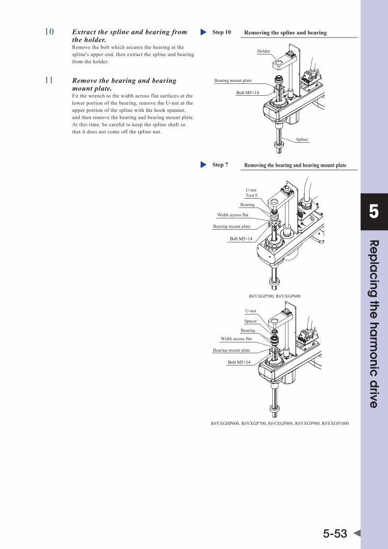
5
Rep
lac
ing the
harm
onic
drive
5-53
10 Extract the spline and bearing from the holder.Remove the bolt which secures the bearing at the spline's upper end, then extract the spline and bearing from the holder.
Removing the spline and bearingStep 10
Bolt M5×14
Bearing mount plate
Holder
Spline
11 Remove the bearing and bearing mount plate.Fit the wrench to the width across flat surfaces at the lower portion of the bearing, remove the U-nut at the upper portion of the spline with the hook spanner, and then remove the bearing and bearing mount plate. At this time, be careful to keep the spline shaft so that it does not come off the spline nut.
Removing the bearing and bearing mount plateStep 7
Bearing mount plate
Bearing
U-nut Tool E
Width across flat
Bolt M5×14
U-nut
Spacer
Bearing
Width across flat
Bearing mount plate
Bolt M5×14
R6YXGP500, R6YXGP600
R6YXGHP600, R6YXGP700, R6YXGP800, R6YXGP900, R6YXGP1000

5
Rep
lac
ing the
harm
onic
drive
5-54
12 Remove the bolt of the spline nut, and then remove the spline nut.
Spline nut
Shaft
O-ring
V-ring
Bolt M4×10(M5×14)
Do not remove the sleeveand V-ring from the spline nut.
Removing the spline nutStep 12
* Values in parentheses apply to the R6YXGHP600, R6YXGP700, R6YXGP800, R6YXGP900 and R6YXGP1000.
NOTE ano-ringisfittedtotheshaft.Replacethiso-ringwithanewone.atthistime,donotremovethev-ringandsleeve.
13 Pull out the R-axis motor.Remove the bolts that secure the R-axis motor and pull out the R-axis motor while turning the R-axis.
NOTE ano-ringisplacedbetweentheR-axismotorflangeandtheY-axis arm. Replace this O-ring with a new one.
14 Pull out the wave generator from the R-axis motor.Loosen two set screws of the wave generator, and then pull out the wave generator from the R-axis motor shaft.
NOTE An O-ring is placed between the R-axis motor shaft and the wave generator. Replace this O-ring with a new one.
Removing the R-axis motorStep 13
O-ring
Bolt M5×14(M6×16)
R-axis motor
* Values in parentheses apply to the R6YXGHP600, R6YXGP700, R6YXGP800, R6YXGP900 and R6YXGP1000.
Removing the wave generatorStep 14
Wave generator(Harmonic drive)
M4 set screw(Supplied with the harmonic drive.)
R-axis motor
O-ring

5
Rep
lac
ing the
harm
onic
drive
5-55
15 Remove the harmonic drive.Remove the bolts that secure the harmonic drive, and then remove the harmonic drive.
O-ring
Bolt M3×14(M3×16)
Removing the harmonic driveStep 15
* Values in parentheses apply to the R6YXGHP600, R6YXGP700, R6YXGP800, R6YXGP900 and R6YXGP1000.
NOTE ano-ringisfittedtotheharmonicdrive.Replacethiso-ringwith a new one.
16 Remove the bolts that secure the shaft, and the panhead bolt and nut from the harmonic drive, and then remove the shaft.For the R6YXGHP600, R6YXGP700, R6YXGP800, R6YXGP900 and R6YXGP1000, remove the dog and bolt.
NOTE An O-ring is placed between the harmonic drive
Removing the shaftStep 16
Harmonic drive
Shaft
Bolt M3×25
O-ring
O-ring
M4 nut
Panhead boltM3×30
R6YXGP500, R6YXGP600
R6YXGHP600, R6YXGP700, R6YXGP800, R6YXGP900, R6YXGP1000
Shaft
O-ring
O-ring
Harmonic driveDog
Bolt M3×25
Bolt M3×30

5
Rep
lac
ing the
harm
onic
drive
5-56
■ Replacement and reassembly
Follow the steps below to replace the harmonic drive with a new one and reassemble it.
1 Apply the harmonic grease to a new wave generator.For details about how to apply the grease, see the Fig. below.
Step 1 Applying the harmonic grease
Apply the grease to the gear clearances.
Apply the grease to the portion below the end face seal thinly so that it is not applied to the end face seal.
Never apply the grease to any parts other than the balls.
Grease thickness is 0.5 mm or less above the end face seal lip.
Harmonic grease• Apply the grease to the outer periphery.• Check the upper and lower coat thicknesses.6.2g (7g)
End face seal lip• Apply a small amount of the grease only to the lip.• Never leave the grease inside the lip.
New harmonic drive (1)
Flex spline
Wave generator ball• Fill the ball spaces with the harmonic grease.
Apply the grease to this portion.
Total grease amount, 1.8g (3g)
* Values in parentheses apply to the R6YXGHP600, R6YXGP700, R6YXGP800, R6YXGP900 and R6YXGP1000.
2 Secure the new wave generator to the R-axis motor.1. Fit the O-ring (6) to the inside of the new wave
generator.
2. Insert the wave generator into the inner end of the R-axis motor shaft and secure it with two set screws while pressing the wave generator with a load of about 1kg.
3. The wave generator deflection must satisfy the values shown in the Fig. on the right. Also make sure that the O-ring does not drop.
Securing the wave generatorStep 2
1kg
Wave generator(Harmonic drive)
R-axis motor
O-ring (6)
M3 set screw(Supplied with the harmonic drive.)Tool C
A
B
A
B
Deflection by turning the motor shaftA: 0.06mm or lessB: 0.10mm or less
3 Apply the harmonic grease to the flex spline.For details about how to apply the harmonic grease, see the Fig. stated in step 1.

5
Rep
lac
ing the
harm
onic
drive
5-57
4 Secure the harmonic drive to the shaft.1. Degrease the upper and lower installation
surfaces of the harmonic drive.
2. Degrease the harmonic drive installation surface of the shaft.
3. Fit the new O-ring (3) coated with the harmonic grease into the groove in the shaft.
4. Secure the harmonic drive to the shaft with new bolts (9).
Securing the harmonic driveStep 4-5
Panhead bolt (10), Tool D
11
Make the temporarily secured bolt matched with the spot facing position.
Degrease the mating surface.
Shaft
New O-ring (3)
Degrease the installation surface.
O-ring (2)
Degrease the installation surface.
Temporarily tightened bolt New bolt (9) Tool B
Bolt (11)Tool B(Be aware that this bolt differs in length from bolt (9).)
Dog (12)
Temporarily tightened bolt New bolt (9) Tool B
Shaft
O-ring (2)
Degrease the installation surface.
Degrease the installation surface.
New O-ring (3)
Degrease the installation surface.
Make the temporarily secured bolt matched with the spot facing position.
R6YXGP500, R6YXGP600
R6YXGHP600, R6YXGP700, R6YXGP800, R6YXGP900, R6YXGP1000
CAUTION Never remove the temporarily secured bolt. Doing so may cause a misalignment.
5 Secure the panhead bolt and nut (bolt and dog (12) for the R6YXGHP600, R6YXGP700, R6YXGP800, R6YXGP900 and R6YXGP1000) to their original positions.It is not necessary to apply any grease to the panhead bolt (10) and bolt (11).
6 Tighten the bolts and panhead bolts in the order shown below.1. Using the wrench, tighten the bolts and panhead
bolts manually in the order indicated by circled numbers.
2. Using the torque driver, tighten the bolts and panheadboltstoapproximately50%ofthespecified torque in the order indicated by circled numbers.
3. Tighten the bolts and panhead bolts to the specified torque in the order indicated by circled numbers.
4. Finally, check that the bolts and panhead bolts are tightened to the specified torque.
CAUTION Do not allow the O-ring to get caught out of the groove during reassembly. If the robot is operated with the O-ring left caught out of the groove, this may cause a malfunction.
Bolt and panhead bolt tightening orderStep 6

5
Rep
lac
ing the
harm
onic
drive
5-58
7 Install the O-ring (2).1. Degrease the installation surface of the Y-axis
arm where the harmonic drive is to be installed.
2. Fit the O-ring (2) coated with a small amount of the harmonic grease into the O-ring groove of the new harmonic drive. If it is difficult to fit the O-ring into the groove, slightly stretch the O-ring.
Installing the harmonic driveStep 7-8
New bolt (8)Tool B
O-ring (2) supplied with harmonic drive
Y-axis arm harmonic driveDegrease the mating surface.
・ Reassemble while aligning the temporarily tightened bolts with the counterbored positions in the Y-axis arm. (R6YXGP500 and R6YXGP600)・ For the R6YXGHP600, R6YXGP700, R6YXGP800, R6YXGP900 and R6YXGP1000, align the phase as shown in the Fig. stated in step 9.
CAUTION Do not allow the O-ring to get caught out of the groove during reassembly. If the robot is operated with the O-ring left caught out of the groove, this may cause a malfunction.
8 Secure the harmonic drive to the Y-axis arm.From the upper portion of the Y-axis arm, secure the harmonic drive to the Y-axis arm.
9 Tighten the bolts in the order shown below.1. Using the wrench, tighten the bolts manually in
the order indicated by circled numbers.
2. Using the torque driver, tighten the bolts to approximately50%ofthespecifiedtorqueintheorder indicated by circled numbers.
3. Tighten the bolts to the specified torque in the order indicated by circled numbers.
4. Finally, check that the bolts are tightened to the specified torque.
CAUTION Do not allow the O-ring to get caught out of the groove during reassembly. If the robot is operated with the O-ring left caught out of the groove, this may cause a malfunction.
10 Fit the new O-ring (5) coated with the harmonic grease into the O-ring groove of the Y-axis arm.
CAUTION Do not allow the O-ring to get caught out of the groove during reassembly. If the robot is operated with the O-ring left caught out of the groove, this may cause a malfunction.
11 Insert the R-axis motor into the Y-axis arm.Insert the R-axis motor into the Y-axis arm while turning the R-axis. Tighten the bolts while turning the R-axis.
Mounting bolt tightening orderStep 9
Align the installationphase so that thetemporarily tightenedbolts are in positionsof 0°, 90°, 180° and270°.
R6YXGP500, R6YXGP600 R6YXGHP600, R6YXGP700, R6YXGP800, R6YXGP900, R6YXGP1000
Inserting the R-axis motorStep 10-11
New O-ring (5)
New bolt (7)Tool A
R-axis motor

5
Rep
lac
ing the
harm
onic
drive
5-59
12 Fit the new O-rings (4) coated with the harmonic grease into the groove at the lower portion of the shaft.
Securing the spline nutStep 12-13
End face seal (14)Check that the V-ring isseated on the sleeve.
Do not remove the sleeveand V-ring from the spline nut.
Spline nut
Shaft
New O-ring (4)
Bolt (13)
CAUTION Do not allow the O-ring to get caught out of the groove during reassembly. If the robot is operated with the O-ring left caught out of the groove, this may cause a malfunction.
13 Secure the spline nut to the shaft with the bolt (13).Checkthatthesleeveandv-ringareinstalledcorrectly.
14 Secure the bearing.Fit the bearing plate and bearing (16) over the top of the spline, then secure the bearing with bearing nut (15). (At this time, utilize the width across flat surfaces of the spline in the same manner as the U-nut is loosened.) For the R6YXGHP600, R6YXGP700, R6YXGP800, R6YXGP900 and R6YXGP1000, be careful not to forget the spacer.
Bearing mount plate
Bearing (16)
Bearing nut (15)Tool E
Width across flat
Bolt (17)
Bearing nut (15)
SpacerBearing (16)
Width across flat
Bearing mount plae
Bolt (17)
R6YXGP500, R6YXGP600
R6YXGHP600, R6YXGP700, R6YXGP800, R6YXGP900, R6YXGP1000
Securing the bearingStep 14
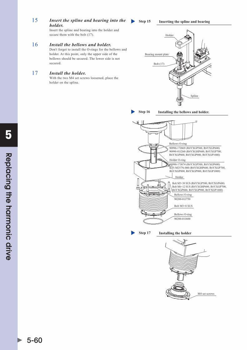
5
Rep
lac
ing the
harm
onic
drive
5-60
15 Insert the spline and bearing into the holder.Insert the spline and bearing into the holder and secure them with the bolt (17).
Inserting the spline and bearingStep 15
Bearing mount plate
Holder
Spline
Bolt (17)
16 Install the bellows and holder.Don't forget to install the O-rings for the bellows and holder. At this point, only the upper side of the bellows should be secured. The lower side is not secured.
17 Install the holder.With the two M4 set screws loosened, place the holder on the spline.
Installing the bellows and holder.Step 16
Holder
Bolt M3×8 SUS
Bellows O-ring90200-01J600
Bellows O-ring90200-01J750
Bellows O-ring90990-17J069 (R6YXGP500, R6YXGP600)90990-01J260 (R6YXGHP600, R6YXGP700, R6YXGP800, R6YXGP900, R6YXGP1000)
Holder O-ring90990-17J074 (R6YXGP500, R6YXGP600)K65-M257N-000 (R6YXGHP600, R6YXGP700, R6YXGP800, R6YXGP900, R6YXGP1000)
Bolt M5×30 SUS (R6YXGP500, R6YXGP600)Bolt M6×12 SUS (R6YXGHP600, R6YXGP700, R6YXGP800, R6YXGP900, R6YXGP1000)
Installing the holderStep 17
M4 set screws

5
Rep
lac
ing the
harm
onic
drive
5-61
18 Install the tool flange.1. Place the tool flange on the spline shaft.
2. Align the spline positioning holes with the tool flange positioning holes, then screw in the positioning bolts.
3. Secure the tool flange by firmly tightening the 4 M6 bolts in a uniform manner.
4. Move the holder (previously placed on the spline shaft) against the tool flange, then tighten the 2 M4 set screws. At this time, be sure that one of the set screws is being screwed in against the chamfered part of the spline shaft.
5. Finally, secure the lower part of the bellows to the holder.
Installing the tool flangeStep 18
Damper
M6 boltPositioning bolt
Tool flange
Seal washer90990-36J006
19 Install the bracket.Replace the seal with a new one.
Installing the tool flangeStep 19
M4x35
SealKDN-M1568-000
SealKAD-M22KB-100
20 Connect the connectors of the R-axis motor power wire RM and resolver wire RP, and the round terminal of the R-axis motor.
21 Reattach the cover.
■ Aging
1 Go out of the safety enclosure.
2 Turn on the controller.Check that no one is inside the safety enclosure, and then turn on the controller.
CAUTION After the harmonic drive has been replaced, it is necessary to perform the absolute reset and set the standard coordinates and point data again. Make the adjustments while referring to Chapter 3 “Adjusting the robot” in the Installation Manual.
3 Perform the aging.Performtheagingfor30minutesat5%speedandforanother30minutesat20%speedbyrotatingtheR-axisarmasmuchas possible (at least 10°).
Reattaching the coverStep 19-21
Cover
Button bolt M3×8
The round terminal of the R-axismotor is present inside here.So, connect this terminal.
Cover
Bolt M3×20 (M3×16)
* Values in parentheses apply to the R6YXGHP600, R6YXGP700, R6YXGP800, R6YXGP900 and R6YXGP1000.


Chapter 6 Replacing the machine harness
Contents
1. Replacing the machine harness 6-11.1 R6YXGLC(P)250, R6YXGLC(P)350, R6YXGLC(P)400, R6YXGLC(P)500, R6YXGLC(P)600 6-1
1.2 R6YXGP500, R6YXGP600, R6YXGHP600, R6YXGP700, R6YXGP800, R6YXGP900, R6YXGP1000 6-7
2. Y-axis arm side I/O connector replacement 6-16
3. Base side I/O connector replacement 6-17


6
Rep
lac
ing the
ma
chine
harne
ss
6-1
1. Replacing the machine harnessCAUTION • somesealsareaffixed.Whenremovingsuchseal,peelofftheadhesiveagentandreplacethesealwithanewone. • Ifthebolttighteningtorqueisnotinstructed,seethetighteningtorquestatedin“2.Replacementprocedureforharmonicdrive”in Chapter 5. • anabsoluteresetisrequiredafteramachineharnessreplacement.
1.1 R6YXGLC(P)250, R6YXGLC(P)350, R6YXGLC(P)400, R6YXGLC(P)500, R6YXGLC(P)600The following shows the parts necessary for the replacement work.
1. Replacement parts
Part Name Part No. Part No. / Specs Q'ty Remarks
1 Bolt 91380-03010 M3×10, stainless 4 Spare parts
2 O-ring 90990-17J021 Cross section diameter: 1.5 Inner diameter: 52.00 1
3 Seal washer 90990-36J008 SWS 3×6.4 8
4 Seal Kdm-m1315-000 1
5 Bolt 91380-04018 M4×18, stainless 4 Spare parts
6 Bolt 91380-03018 M3×18, stainless 4 Spare parts
7 Seal Kdm-m1327-000 1
8 Joint $TSH4-M5M Tsh4-m5m(KoGanEI) 8 Spare parts
9 Harness securing bolt 91312-03018 M3, length: 18 4 Spare parts
10 Screw for round terminal 97602-04308 M4, length: 8 2 Spare parts
11 Lock washer for round terminal 90172-00J040 For M4 4 Spare parts
12 Screw for round terminal 97602-04306 M4, length: 6 2 Spare parts
13 Machine harness
Kdm-m4843-001 1 R6YXGLP250 (*1)
Kdm-m4843-101 1 R6YXGLP350 (*1)
Kdm-m4843-201 1 R6YXGLP400 (*1)
Kdm-m4843-301 1 R6YXGLP500 (*1)
Kdm-m4843-401 1 R6YXGLP600 (*1)
Kdm-m4843-501 1 R6YXGLC250 (*1)
Kdm-m4843-601 1 R6YXGLC350 (*1)
Kdm-m4843-701 1 R6YXGLC400 (*1)
Kdm-m4843-801 1 R6YXGLC500 (*1)
Kdm-m4843-901 1 R6YXGLC600 (*1)
*1: "XG(L)P" indicates dust/drip proof specs., and "XG(L)C" indicates clean room specs.

6
Rep
lac
ing the
ma
chine
harne
ss
6-2
2. Other tools
Name Part No. Manufacturer Remarks
Cloth rag
Hex wrench set
Tie band
Phillips screwdriver
Pliers
Torque wrench
Screw thread locking agent Loctite 241 Henkel Medium-strength type (blue)
Silicon grease G-501 shin-EtsuChemical 3.0g
■ Removal
Follow the steps below to disconnect the machine harness.
1 Turn off the controller power.
2 Place a sign indicating the robot is being adjusted.
3 Enter the safety enclosure.
4 Remove the Y-axis arm cover.Remove the cover while referring to "1. Attaching, detaching, and replacing the cover" in Chapter 2.
Removing the Y-axis arm coverStep 4
Y-axis arm cover
5 Remove the air tubes and round terminals.Remove the air tubes and round terminals (round terminals for the white and yellow/green wires). Be careful not to drop any lock washer or screw.
6 Disconnect the wiring connector.Disconnect the connector (black/15 pins) for the user wiring and the wiring connector. RemovalStep 5-7
Air tube
Air tube
Round terminals of machine harness
Screw M4×6
Lock washer
The position of the round terminal may differ according to the model in question.

6
Rep
lac
ing the
ma
chine
harne
ss
6-3
7 Disconnect the machine harness from the stay.Remove the bolts and disconnect the machine harness from the stay. Remove also the seals.
Disconnecting the machine harnessStep 7
Stay
Seal
Seal washer
Machine harnessBolt M3×18
NOTE Be sure to replace the seal and seal washer with new ones.
8 Disconnect the harness from the Y-axis arm cover.
9 Remove the base rear cover.
10 Disconnect the air tube, connector (black/15 pins) for the user wiring, and the round terminals (white and yellow/green wires).
NOTE Be sure to replace the seal with a new one.
11 Disconnect the harness.Remove the bolt, lock nut, and seal washer, and disconnect the harness and remove the O-ring.
Disconnecting the harnessStep 11
Bolt M3×18
Harness
Lock nut
O-ring
Seal washer
NOTE Be sure to replace the O-ring and seal washer with new ones.
Removing the base rear coverStep 9-10
Seal
Base rear cover
Bolt M4×18
Screw
Round terminal of machine harness
Lock washer
4-air tube
6-air tube
The position of the round terminal may differ according to the model in question.

6
Rep
lac
ing the
ma
chine
harne
ss
6-4
12 Disconnect the ø4-air tubes.Disconnect the user wiring connector and joints from the harness holder.
Disconnecting the 4-air tubesStep 12
Bolt M3×10Connector for user wiring
Harness
Holder
Joint
4-air tube
■ Assembly
Assemble a new machine harness in the reverse order of removal.
1 Reconnect the user wiring connectors and joints that have been disconnected to a new harness ASSY.At this time, do not connect the air tubes. Turn the clamp nut at the clamp position shown in the Fig. on the right to tighten it so that the cable does not come off and turn.
Reconnecting the user wiring connector and jointsStep 1
Bolt (1)Connector for user wiring
Harness (13)
Cable
Wire
Clamp nut
Holder
Joint (8)
4-air tubes
10mm
CAUTION Be sure to clamp the cable in this step as the silicon grease is applied to the connector later.
2 Reconnect the harness.1. Put the O-ring and washer, and then reconnect
the harness.
2. Tighten the lock nut firmly.
CAUTION Do not allow the O-ring to get caught out of the groove during reassembly. If the robot is operated with the O-ring left caught out of the groove, this may cause a malfunction.
Reconnecting the harnessStep 2
Bolt (9)
Harness
Lock nut
New O-ring (2)
New seal washer (3)

6
Rep
lac
ing the
ma
chine
harne
ss
6-5
3 Apply the silicon grease.To prevent rubbing, apply the grease to the inside diameter portion of the hollow shaft, and the cable and air tube. (See the Fig. on the right.) Silicon grease: G-501(shin-EtsuChemical),1.5g
Applying the silicon greaseStep 3
Air tube
Cable
Inside diameter portion of hollow shaft
4 Reconnect the air tubes, connector for the user wiring (black/15 pins), and round terminals (white and yellow/green wires).
5 Reattach the base rear cover.
6 Place the Y-axis arm cover on the base.Pass the cover through the harness while carefully checking the orientation of the Y-axis arm cover, and then place the Y-axis arm cover on the base.
7 Reconnect the ø4-air tube.Cut the air tube to an appropriate length so that it is not broken.
NOTE After the air tube has been connected, supply the air to the air tube to check that the air supply meets the joint color on the base side.
8 Reconnect the harness.Put a new seal (7) and reconnect the harness with the seal washers (3) and bolts (6).
Reattaching the base rear coverStep 4-5
New seal (4)
Base rear cover
Bolt (5)
Screw (10)
Round terminal of machine harnessLock washer (11)
RedBlue
Black
4-air tube
Black (tube projects from the cable.)
6-air tube
(This tube can be connected to any joint. *1)
Cable
*1 This air tube is the spare tube for the joint suction or air purging.
The position of the round terminal may di�er according to the model in question.
Reconnecting the machine harnessStep 8
Stay
RedBlue
4-air tubeBlack (tube projects from the cable.)
Black
New seal (7)
New seal seal washer (3)
Machine harness
Bolt (6)Apply screw lock (LOCTITE) to the bolt threads (first 3 threads)
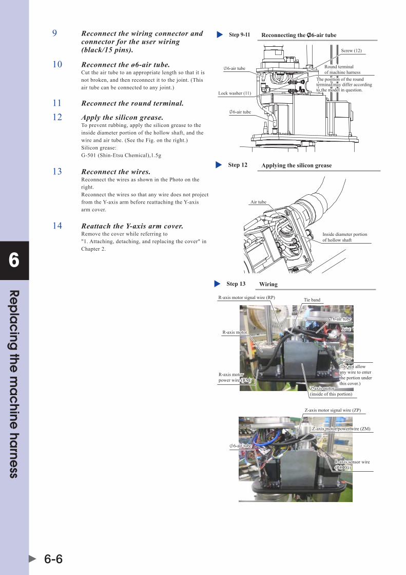
6
Rep
lac
ing the
ma
chine
harne
ss
6-6
9 Reconnect the wiring connector and connector for the user wiring (black/15 pins).
Reconnecting the 6-air tubeStep 9-11
6-air tube
6-air tube
Round terminal of machine harness
Screw (12)
Lock washer (11)
The position of the round terminal may differ according to the model in question.
10 Reconnect the ø6-air tube.Cut the air tube to an appropriate length so that it is not broken, and then reconnect it to the joint. (This air tube can be connected to any joint.)
11 Reconnect the round terminal.
12 Apply the silicon grease.To prevent rubbing, apply the silicon grease to the inside diameter portion of the hollow shaft, and the wire and air tube. (See the Fig. on the right.) Silicon grease: G-501(shin-EtsuChemical),1.5g
Applying the silicon greaseStep 12
Air tube
Inside diameter portion of hollow shaft
13 Reconnect the wires.Reconnect the wires as shown in the Photo on the right. Reconnect the wires so that any wire does not project from the Y-axis arm before reattaching the Y-axis arm cover.
14 Reattach the Y-axis arm cover.Remove the cover while referring to "1. Attaching, detaching, and replacing the cover" in Chapter 2.
WiringStep 13
R-axis motor signal wire (RP)
6-air tube
Joint
Cover(Do not allow any wire to enter the portion under this cover.)
Z-axis motor (inside of this portion)
R-axis motor power wire (RM)
6-air tube
R-axis motor
Z-axis motor signal wire (ZP)
Z-axis motor power wire (ZM)
R-axis sensor wire(RORG)
Tie band
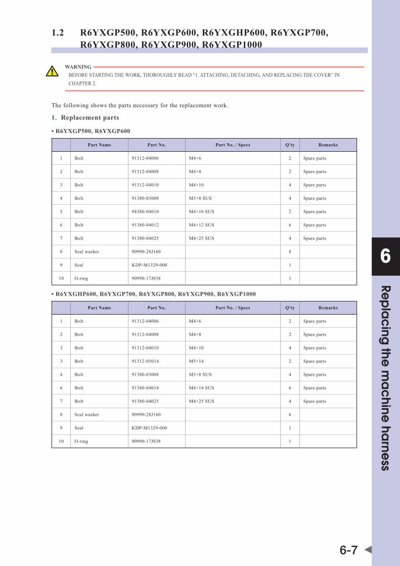
6
Rep
lac
ing the
ma
chine
harne
ss
6-7
1.2 R6YXGP500, R6YXGP600, R6YXGHP600, R6YXGP700, R6YXGP800, R6YXGP900, R6YXGP1000
WARNING bEFoREsTaRTInGThEWoRK,ThoRoUGhLYREad“1.aTTaChInG,dETaChInG,andREPLaCInGThECovER”InChaPTER2.
The following shows the parts necessary for the replacement work.
1. Replacement parts
•R6YXGP500,R6YXGP600
Part Name Part No. Part No. / Specs Q'ty Remarks
1 Bolt 91312-04006 M4×6 2 Spare parts
2 Bolt 91312-04008 M4×8 2 Spare parts
3 Bolt 91312-04010 M4×10 4 Spare parts
4 Bolt 91380-03008 M3×8 SUS 4 Spare parts
5 Bolt 94380-04010 M4×10 SUS 2 Spare parts
6 Bolt 91380-04012 M4×12 SUS 6 Spare parts
7 Bolt 91380-04025 M4×25 SUS 4 Spare parts
8 Seal washer 90990-28J160 8
9 Seal KdP-m1329-000 1
10 O-ring 90990-17J038 1
•R6YXGHP600,R6YXGP700,R6YXGP800,R6YXGP900,R6YXGP1000
Part Name Part No. Part No. / Specs Q'ty Remarks
1 Bolt 91312-04006 M4×6 2 Spare parts
2 Bolt 91312-04008 M4×8 2 Spare parts
3 Bolt 91312-04010 M4×10 4 Spare parts
3 Bolt 91312-05014 M5×14 2 Spare parts
4 Bolt 91380-03008 M3×8 SUS 4 Spare parts
6 Bolt 91380-04014 M4×14 SUS 6 Spare parts
7 Bolt 91380-04025 M4×25 SUS 4 Spare parts
8 Seal washer 90990-28J160 6
9 Seal KdP-m1329-000 1
10 O-ring 90990-17J038 1

6
Rep
lac
ing the
ma
chine
harne
ss
6-8
2. Other tools
Name Part No. Manufacturer Remarks
Cloth rag
Hex wrench set
Tie band
Phillips screwdriver
Pliers
Torque wrench
Screw thread locking agent Loctite 241 Henkel Medium-strength type (blue)
Silicon grease G-501 shin-EtsuChemical 3.0g
■ Removal
Follow the steps below to disconnect the machine harness.
1 Turn off the controller power.
2 Place a sign indicating the robot is being adjusted.
3 Enter the safety enclosure.
4 Remove the cover.Remove the bolts, then detach the cover.
Removing the coverStep 4
Seal washer90990-28J160 (common)
User I/O connector91380-03008
Bolt91380-04012 (R6YXGP500,R6YXGP600)91380-04014 (R6YXGHP600, R6YXGP700, R6YXGP800, R6YXGP900, R6YXGP1000)
Bolt91380-04012 (R6YXGP500,R6YXGP600)91380-04014 (R6YXGHP600, R6YXGP700, R6YXGP800, R6YXGP900, R6YXGP1000)
5 Disconnect the Y-axis speed reduction unit air purge tube, and the ground cable terminal.
Disconnecting the Y-axis speed reduction unit air purge tube, and the ground cable terminalStep 5
Disconnect the Y-axis speed reduction unit air purge tube here.
Ground cable terminal

6
Rep
lac
ing the
ma
chine
harne
ss
6-9
6 Disconnect the ground cable located inside the Y-arm.
Disconnecting the ground cableStep 6
Ground cable terminal
SealKDP-M1329-000
7 Disconnect the user air tubes (red, blue, black).
8 Remove the plate.Remove the bolts, then remove the plate which secures the machine harness.
9 Remove the lock nut.Remove the lock nut (prevents the nut from loosening) at the nut which secures the machine harness to the plate.
10 Remove the cap-cone lock washer.
11 Remove the plate.With the cap-cone in a secured condition, turn the nut on the back face to remove the plate.
12 Remove the 6 joints from the machine harness block, and disconnect the user I/O connector.
Disconnecting the user air tubesStep 7-9
Lock nut91312-04006
Disconnect the user air tubes (red, blue, black) here.
Nut
Bolt91312-04010
Disconnecting the air tubes and round terminalsStep 10-11
Cap-cone
Plate
Cap-cone lock washer91312-04008
Removing the joints and disconnecting the user I/O connectorStep 12
User I/O connector91380-03008
Joints
Joints

6
Rep
lac
ing the
ma
chine
harne
ss
6-10
13 Remove the cover.Remove the cover while referring to "1. Attaching, detaching, and replacing the cover" in Chapter 2.
Removing the coverStep 13
Bolt (R6YXGP500, R6YXGP600)91380-04025
(R6YXGP500, R6YXGP600)KDN-M1315-000
Bolt (R6YXGP500, R6YXGP600)91380-04008Bolt (R6YXGHP600, R6YXGP700, R6YXGP800, R6YXGP900, R6YXGP1000)91380-04010
Bolt (R6YXGHP600, R6YXGP700, R6YXGP800, R6YXGP900, R6YXGP1000)91380-04020
(R6YXGHP600, R6YXGP700, R6YXGP800, R6YXGP900, R6YXGP1000)KDP-M1315-000
14 Disconnect the user air tubes, the ground cable terminal, and the connectors.
Disconnecting the user air tubes, the ground cable terminal, and the connectorsStep 14
Connectors
Disconnect the user air tubes (red, blue, black) here.Match the tube colors to the joint colors on the base side.
Ground cable terminal

6
Rep
lac
ing the
ma
chine
harne
ss
6-11
15 Remove the machine harness.1. Remove the machine harness securing plate from
the base.
2. Remove the cap-cone from the securing plate (also remove the cap-cone lock washer).
3. Remove the machine harness block which is secured to the base.
4. Remove the machine harness in the upward direction.
Removing the machine harnessStep 15
Machine harness securing plate
Cap-cone lock washer
Bolt91312-04006
O-ring90990-17J038
Bolt91312-04008
Bolt91312-05014
Cap-cone
Bolt91380-04025
Bolt91380-04025
O-ring90990-17J038
Bolt91312-04008
Bolt91380-04010
Seal washer90990-28J159
Block
Base
R6YXGP500, R6YXGP600
R6YXGHP600, R6YXGP700, R6YXGP800, R6YXGP900, R6YXGP1000
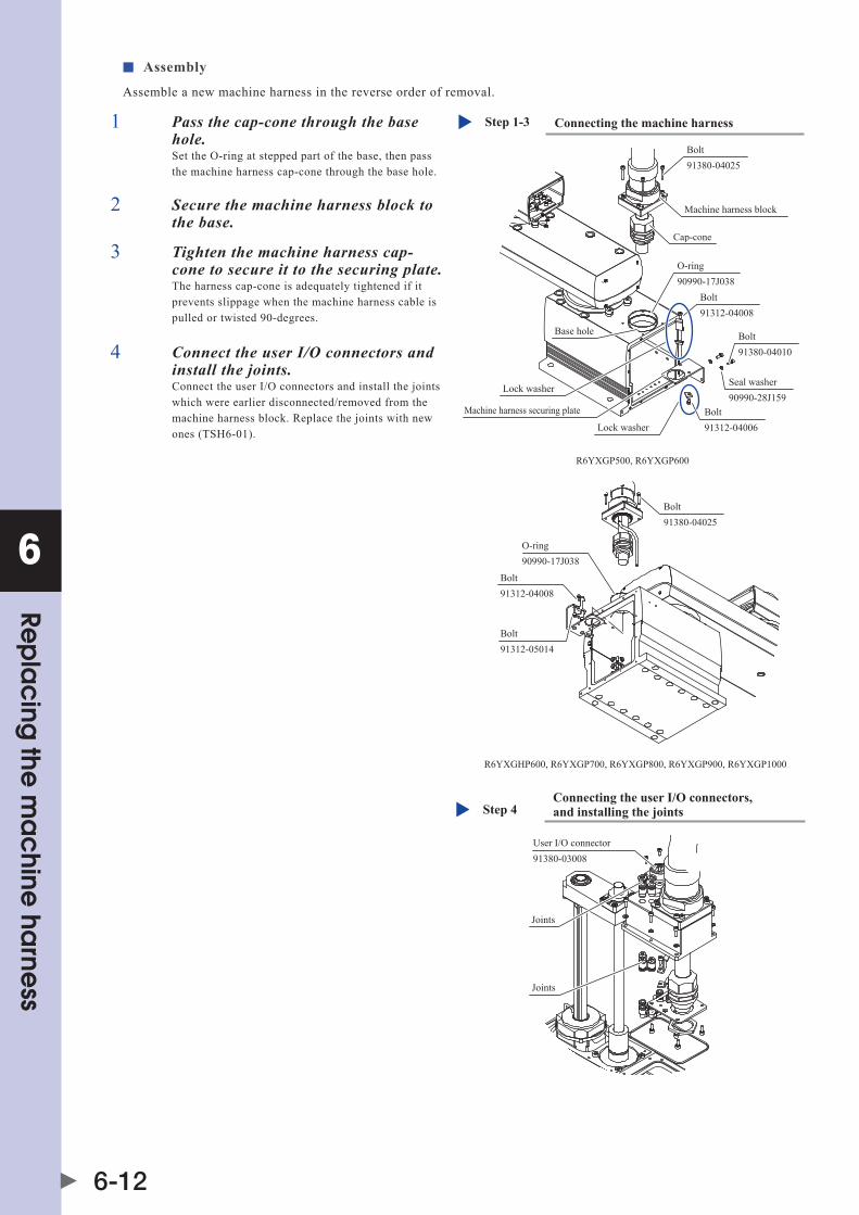
6
Rep
lac
ing the
ma
chine
harne
ss
6-12
■ Assembly
Assemble a new machine harness in the reverse order of removal.
1 Pass the cap-cone through the base hole.Set the O-ring at stepped part of the base, then pass the machine harness cap-cone through the base hole.
2 Secure the machine harness block to the base.
3 Tighten the machine harness cap-cone to secure it to the securing plate.The harness cap-cone is adequately tightened if it prevents slippage when the machine harness cable is pulled or twisted 90-degrees.
Connecting the machine harnessStep 1-3
O-ring90990-17J038
Bolt91312-04008
Base hole
Lock washer
Lock washer
Machine harness securing plate
Bolt91312-05014
Bolt91380-04025
Bolt91380-04025
O-ring90990-17J038
Bolt91312-04008
Bolt91380-04010
Seal washer90990-28J159
Machine harness block
Cap-cone
R6YXGP500, R6YXGP600
R6YXGHP600, R6YXGP700, R6YXGP800, R6YXGP900, R6YXGP1000
Bolt91312-04006
4 Connect the user I/O connectors and install the joints.Connect the user I/O connectors and install the joints which were earlier disconnected/removed from the machine harness block. Replace the joints with new ones (TSH6-01).
Connecting the user I/O connectors, and installing the jointsStep 4
User I/O connector91380-03008
Joints
Joints

6
Rep
lac
ing the
ma
chine
harne
ss
6-13
5 Install the cap-cone and the cap-cone lock washer.In the same manner as at the base side, install the machine harness cap-cone on the securing plate, together with its lock washer. The securing plate and the lock washer which were earlier removed from the machine harness are to be used.
Installing the cap-cone and the cap-cone lock washerStep 5
Cap-cone
Plate
Cap-cone lock washer91312-04008
6 Route the air tube.After installing the cap-cone, route the air tube (1 tube) through the plate's slot.
7 Apply silicone grease.To prevent rubbing damage, apply silicone grease to the inside of the hollow shaft, to the cable, and to the air tube (see the figure at right). siliconegrease: G-501(shin-EtsuChemical Co., Ltd.) 1.5g
8 Secure the plate to the block.After installing the plate, secure to the block with M4 screws.
9 Connect the user air tubes.The user air tubes (red, blue, black) pass through the compound cable. Cut these tubes approximately 30mm from the end of the outlet tape. Connect the same air tubes which were earlier disconnected. Install the air joints at the inner side of the opposite-side block.
Securing the plateStep 8
Earlier disconnected air tubes and joints (elbow)
Connect the user tubes (red, blue, black) after cutting them approximately 30mm from the end of the outlet tape.
Cap-cone securing plate
Bolt91312-04010
Tape
Routing the air tubeStep 6
Cap-cone nutRoute the air tube
Cap-cone lock washer91312-04006
Applying silicone greaseStep 7
Apply silicone grease to the inside of the flexible duct.

6
Rep
lac
ing the
ma
chine
harne
ss
6-14
10 Replace the seal with a new one. Installing the joints and connecting the ground cable terminalStep 10-12
Ground cable terminal
SealKDP-M1329-000
Cut the Y-axis speed reduction unit air purge tube approximately 70mm from the plate, and connect the Y-arm's inner joint (elbow).
11 Install the joints (elbow).The Y-axis speed reduction unit air purge tube passes through the plate's slot. Cut this tube approximately 70mm from the plate, and connect the Y-arm's inner joint (elbow).
12 Connect the Y-arm's inner ground cable terminal to the plate.
13 Connect the ground cable to the Y-arm's inner tap.
14 Use the M4 bolts to connect the block to the Y-arm.
Connecting the ground cableStep 13
Ground cable terminal
Securing to the Y-armStep 14
Seal washer90990-28J160 (common)
M4 bolt91380-04012 (R6YXGP500, R6YXGP600)91380-04014 (R6YXGHP600, R6YXGP700, R6YXGP800, R6YXGP900, R6YXGP1000)

6
Rep
lac
ing the
ma
chine
harne
ss
6-15
15 Secure the machine harness securing plate to the base.
Securing the machine harness securing plateStep 15
Machine harness securing plate
Cap-cone
Base
16 Apply silicone grease.To prevent rubbing damage, apply silicone grease to the inside of the hollow shaft, to the cable, and to the air tube (see the figure at right). siliconegrease: G-501(shin-EtsuChemical Co., Ltd.) 1.5g
Applying silicone greaseStep 16
Apply silicone grease to the inside of the flexible duct from the inner side of the base.
17 Connect the connectors and tubing.Secure the ground cable terminal to the tap inside the base, then connect the connectors and tubing.
18 Replace the seal with a new one.
19 Attach the cover.
Connecting the connectors and tubingStep 17
Connector
Cut the user tubes (red, blue, black) to approximately 50mm, then connect to the base-side joints.
Ground cable terminal
Replacing the seal & attaching the coverStep 18-19
Bolt91380-04025 (R6YXGP500, R6YXGP600)91380-04020 (R6YXGHP600, R6YXGP700, R6YXGP800, R6YXGP900, R6YXGP1000)
SealKDN-M1315-000 (R6YXGP500, R6YXGP600)KDP-M1315-000 (R6YXGHP600, R6YXGP700, R6YXGP800, R6YXGP900, R6YXGP1000)
Bolt91380-04008 (R6YXGP500, R6YXGP600)91380-04010 (R6YXGHP600, R6YXGP700, R6YXGP800, R6YXGP900, R6YXGP1000)

6
Rep
lac
ing the
ma
chine
harne
ss
6-16
2. Y-axis arm side I/O connector replacement1. Replacement parts
Part Name Part No. Part No. / Specs Q'ty Remarks
1 I/O connector Kdm-m4873-000 1 Spare parts
2 I/O connector securing bolts 91380-03010 M3, length: 10 stainless 4 Spare parts
2. Other tools
Name Part No. Manufacturer Remarks
Hex wrench set
Screw thread locking agent Loctite 241 Henkel Medium-strength type (blue)
■ Removal
Follow the steps below to disconnect the machine harness.
1 Turn off the controller power.
2 Place a sign indicating the robot is being adjusted.
3 Enter the safety enclosure.
4 Using the machine harness replacement procedure, disassemble to the point where the Y-axis arm cover is removed.
5 Disconnect the machine harness's Y-axis arm side I/O connector.
Removing the Y-axis arm side I/O connectorStep 5
Bolt (2)Apply *screw lock (LOCTITE) to the bolt threads (first 3 threads)
I/O connector (1)
6 Remove the bolt, then disconnect the I/O connector.
■ Assembly
Install the new I/O connector and reassemble by reversing the disassembly procedure.

6
Rep
lac
ing the
ma
chine
harne
ss
6-17
3. Base side I/O connector replacement1. Replacement parts
Part Name Part No. Part No. / Specs Q'ty Remarks
1 I/O connector Kdm-m4874-000 1
2 I/O connector securing bolts 91380-03012 M3, length: 12 stainless 4 Spare parts
3 Bracket securing bolts 91380-03006 M3, length: 6 stainless 2 Spare parts
4 Seal washer 90990-36J008 For M3 stainless 4 Spare parts
2. Other tools
Name Part No. Manufacturer Remarks
Hex wrench set
Screw thread locking agent Loctite 241 Henkel Medium-strength type (blue)
■ Removal
Follow the steps below to disconnect the machine harness.
1 Turn off the controller power.
2 Place a sign indicating the robot is being adjusted.
3 Enter the safety enclosure.
4 Using the machine harness replacement procedure, disassemble to the point where the base rear cover is removed.
5 Remove the bracket, then disconnect the user wiring connector.
Disconnecting the user wiring connectorStep 5
Bolt 3
Bracket
User wiring connector
6 Disconnect the machine harness's base side I/O connector.
■ Assembly
Install the new I/O connector and reassemble by reversing the disassembly procedure.
Disconnecting the base side I/O connectorStep 6
Seal washer (4)
Bolt (2)Apply *screw lock (LOCTITE) to the bolt threads (first 3 threads)
I/O connector (1)


Chapter 7 Replacing the bellows
Contents
1. Replacing the upper bellows 7-1
2. Replacing the lower bellows 7-3


7
Rep
lac
ing the
be
llows
7-1
1. Replacing the upper bellowsThe following shows the replacement parts.
1. Replacement parts
Part name Part No. Q’ty Remarks
1 O-ring 90200-01J350 2
2 Bellows Kdm-m1899-000 1
3 Rubber Kdm-m189J-000 2
4 Clamp Kdm-m1890-000 2 Spare parts
2. Other tools
Name Part No. Manufacturer Remarks
Phillips screwdriver
Calipers, etc.
1 Turn on the controller.Check that no one is inside the safety enclosure, and then turn on the controller.
2 Press the emergency stop button.Press the emergency stop button on the PB to put the robot in the emergency stop status.
3 Place a sign indicating the robot is being adjusted.Place a sign indicating the robot is being adjusted, to keep others from operating the controller or operation panel.
4 Enter the safety enclosure while holding the PB.
5 Disconnect the user wiring and tubing from the spline.Disconnect all of the user wiring and tubing that have passed through the spline from the spline.
6 Loosen the screw of the clamp.
7 Remove the bellows and remove the O-ring.
Removing the bellows and O-ringStep 7
Clamp (4)
Rubber (3)
Rubber (3)
Screw
Screw
Bellows (2)
Clamp (4)
O-ring (1)

7
Rep
lac
ing the
be
llows
7-2
8 Install new bellows (2), O-ring (1), and rubber (3).Reassemble the parts in the reverse order of removal. If the O-ring is not replaced with a new one, the dust/drip proof performance or the degree of cleanliness may lower. In particular, carefully check the rubber (3) mounting position and bellows clamp position while referring to the Fig. on the right.
3
12 1.5
Rubber mounting and bellows clamp positionsStep 8
The bellows (2) and the end face of the rubber (3) are flush with the end face of the clamp ring.
Clamp ring
Clamp ring
Rubber (3)
Rubber (3)
Bellows (2),end face of the rubber (3)
Install the bellows, clamp, and rubber at the positions shown in the Fig. above.(Tolerance: ± 0.5mm)
Almost this orientation
Rubber (3)
Reattach the clampso that the projectionpart of the clamp shownin the Photo is locatedin the clearance of theblack rubber (3).
Adhere to the outside of the bellows.

7
Rep
lac
ing the
be
llows
7-3
2. Replacing the lower bellowsThe following shows the replacement parts.
1. Replacement parts
Part name Part No. Q’ty Remarks
1 O-ring 90200-01J500 2
2 O-ring 90200-01J350 2
3 Bellows Kdm-m1897-000 1
4 Rubber Kdm-m1898-000 1 Spare parts
5 Rubber Kdm-m189J-000 1
6 Clamp Kdm-m189a-000 1 Spare parts
7 Clamp Kdm-m1890-000 1 Spare parts
2. Other tools
Name Part No. Manufacturer Remarks
Phillips screwdriver
Calipers, etc.
1 Turn on the controller.Check that no one is inside the safety enclosure, and then turn on the controller.
2 Press the emergency stop button.Press the emergency stop button on the PB to put the robot in the emergency stop status.
3 Place a sign indicating the robot is being adjusted.Place a sign indicating the robot is being adjusted, to keep others from operating the controller or operation panel.
4 Enter the safety enclosure while holding the PB.
5 Disconnect the user wiring and tubing from the spline.Disconnect all of the user wiring and tubing that have passed through the spline from the spline.
6 Loosen the screw of the clamp.
Loosening the screw of the clampStep 6
Clamp (7)
Clamp (6)Screw
Screw
Bellows (3)
7 Remove the bellows and remove the O-ring.
Removing the bellows and O-ringsStep 7
Rubber (4)
Rubber (5)
O-ring (1)
O-ring (2)

7
Rep
lac
ing the
be
llows
7-4
8 Install new bellows (3), O-rings (1) and (2), and rubbers (4) and (5).Reassemble the parts in the reverse order of removal. If the O-ring is not replaced with a new one, the dust/drip proof performance or the degree of cleanliness may lower. In particular, carefully check the rubbers (4) and (5) mounting positions and bellows clamp position while referring to the Fig. on the right.
76.6
22
1
Rubber mounting and bellows clamp positionsStep 8
Rubber (5)
Rubber (4)
Almost this orientation
Reattach the clamp so that the projection part of the clamp shown in the Photo is located in the clearance between the black rubbers (4) and (5).
Rubber (4) (Adhere to the outside of the bellows.)
Bottom surface of Y-axis arm
Rubber (5) (Adhere to the outside of the bellows.) Bellows (3),
end face of the rubber (5)
Bellows (3),end face of the rubber (4)
Clamp ringClamp ring
Install the bellows, clamp, and rubbers at the positions shown in the Fig. above.(Tolerance: ± 0.5mm)

Chapter 8 Replacing the Z-axis ASSY
Contents
1. Replacing the Z-axis ASSY 8-11.1 R6YXGLC(P)250, R6YXGLC(P)350, R6YXGLC(P)400, R6YXGLC(P)500, R6YXGLC(P)600 8-1
1.2 R6YXGP500, R6YXGP600, R6YXGHP600, R6YXGP700, R6YXGP800, R6YXGP900, R6YXGP1000 8-5


8
8-1
Rep
lac
ing the
Z-axis A
SSY
1. Replacing the Z-axis ASSYTo replace the Z-axis ball screw and Z-axis motor, follow the steps below to replace the Z-axis ASSY.
CAUTION • Ifthebolttighteningtorqueisnotinstructed,seethetighteningtorquestatedin“2.Replacingtheharmonicdrive"inChapter5. • Replacingthez-axiscausesapositionaldeviation.Therefore,followingaz-axisreplacement,anabsoluteresetmustbeperformed, andthepointdatamustbere-specified.
1.1 R6YXGLC(P)250, R6YXGLC(P)350, R6YXGLC(P)400, R6YXGLC(P)500, R6YXGLC(P)600
WARNING bEFoREsTaRTInGThEREPLaCEmEnTWoRK,ThoRoUGhLYREad"1.aTTaChInG,dETaChInG,andREPLaCInGThECovER"InChaPTER2.
1. Replacement parts
Part name OMRON Part No. Part No. / Specs Q’ty Remarks
1
Motor KCY-m4882-000 1
Assembly
Motor securing bolt 91312-04012 M4, length: 12 2
Coupling KCY-m1753-000 1
Ball screw KCY-m1750-000 1
Bearing outer ring holder plate KCY-m1744-000 1
Ball screw support bearing Ka1-m2273-000 1
Lower end damper KCY-m1788-000 1
Bolt for outer ring holder plate 90112-2aJ010 8
Bearing inner ring holder plate KCY-m1778-000 1
Bearing housing KCY-m1712-000 1
2 Ball screw securing bolt 91312-03014 M3, length: 14 4 Spare parts
3 Z-axis assembly securing bolt 91312-04014 M4, length: 14 4 Spare parts
4 Screw for round terminal 97602-04308 M4, length: 8 1 Spare parts
5 Lock washer for round terminal 90172-00J040 For M4 1 Spare parts
2. Other tools
Name Part No. Manufacturer Remarks
Cleaning wipe
Hex wrench set
Tie band
Phillips screwdriver
Torque wrench
Screw thread locking agent Loctite 262 Henkel High strength type (red)

8
8-2
Rep
lac
ing the
Z-axis A
SSY
Follow the steps below to perform the replacement work.
1 Turn off the controller.
2 Place a sign indicating the robot is being adjusted.Place a sign indicating the robot is being adjusted, to keep others from operating the controller or operation panel.
3 Enter the safety enclosure.
4 Remove the Y-axis arm cover.Remove the cover while referring to "1. Attaching, detaching, and replacing the cover" in Chapter 2.
Step 4 Removing the Y-axis arm cover
5 Put on the Z-axis brake and turn off the controller power.1. Press the emergency stop button on the PB and turn on the controller power.
2. Put the Z-axis in the servo free status and move the Z-axis to its upper end.
3. Put on the Z-axis brake and turn off the controller power.
NOTE For details about servo free status and emergency stop, see the OMRON robot controller user’s manual.
6 Cut the tie-band.Cut the tie-band as described in Chapter 6 "1. Replacing the machine harness".

8
8-3
Rep
lac
ing the
Z-axis A
SSY7 Disconnect the round terminal of the Z-axis motor and the Z-axis motor connectors ZM,
ZP, and ZBK.
Step 7 Disconnecting the round terminal and motor connectors
Lock washer (5)
Screw (4)
Round terminal of Z-axis motor
Cover
The position of the round terminal may differ according to the model in question.
8 Remove the Z-axis ASSY.Remove the bolts and remove the Z-axis ASSY.
9 Replace with a new Z-axis assembly (with Z-axis machine reference adjusted).
Step 9 Replacement and reassembly
Bolt (2) *Apply the screw lock.
Z-axis ASSY (1)
Bolt (3)

8
8-4
Rep
lac
ing the
Z-axis A
SSY
10 Secure the Y-axis arm side wiring with a tie band, then connect the connector and install the round terminal as described in machine harness replacement procedure.
NOTE Refer to Chapter 8 "1.3 Robot inner wiring diagram" of the installation manual for XG series standard models..
11 Move to a position outside the safety fence, then turn the controller power ON. Establish an emergency stop status, then enter the safety fence area with the PB in hand.After verifying that the Z-axis is prevented from falling, release the Z-axis brake.
NOTE For the brake release procedure, refer to the "OMRON Robot Controller User's Manual".
While raising and lowering the Z-axis, tighten bolt (2). Apply grease to the ball screw in accordance with the instructions given in the Periodic Inspections section.
12 Reattach the cover.Move down the Z-axis to its lower end, turn off the controller power, and reattach the cover. Reattach the cover while referring to "1. Attaching, detaching, and replacing the cover" in Chapter 2.
13 Go out of the safety enclosure.

8
8-5
Rep
lac
ing the
Z-axis A
SSY1.2 R6YXGP500, R6YXGP600, R6YXGHP600, R6YXGP700, R6YXGP800, R6YXGP900, R6YXGP1000
WARNING bEFoREsTaRTInGThEREPLaCEmEnTWoRK,ThoRoUGhLYREad"1.aTTaChInG,dETaChInG,andREPLaCInGThECovER"InChaPTER2.
1. Replacement parts
• R6YXGP500,R6YXGP600
Part Name OMRON Part No. Part No. / Specs Q'ty Remarks
1 Motor KbF-m4882-002 1
2
Ball screwKbP-m1750-001 Z-axis stroke 200mm 1
Assembly
KbP-m1750-101 Z-axis stroke 300mm 1
Nylon nut KbP-m1778-001 1
Motor and ball screw shaft coupling flange KbP-m1753-003 1
Lower end damper KbP-m1788-001 1
3 Ball screw nut securing bolt 91312-05014 M5, length: 14 4 Must be replaced
4 Motor and ball screw shaft coupling flange securing bolt 91312-03020 M3, length: 20 10 Must be replaced
5 Motor securing bolt 91312-05012 M5, length: 12 2 Must be replaced
6 Motor securing bolt 91312-05016 M5, length: 16 2 Must be replaced
7 Screw for round terminal 97602-04308 M4, length: 8 1 Spare parts
8 Lock washer for round terminal 90172-00J040 For M4 1 Spare parts
• R6YXGHP600,R6YXGP700,R6YXGP800,R6YXGP900,R6YXGP1000
Part Name OMRON Part No. Part No. / Specs Q'ty Remarks
1 Motor KbP-m4882-001 1
2
Ball screwKbP-m1750-001 Z-axis stroke 200mm 1
Assembly
KbP-m1750-201 Z-axis stroke 400mm 1
Nylon nut KbP-m1778-001 1
Motor and ball screw shaft coupling flange KbP-m1753-003 1
Lower end damper KbP-m1788-001 1
3 Ball screw nut securing bolt 91312-05014 M5, length: 14 4 Must be replaced
4 Motor and ball screw shaft coupling flange securing bolt 91312-03020 M3, length: 20 10 Must be replaced
5 Motor securing bolt 91312-05016 M5, length: 16 2 Must be replaced
6 Motor securing bolt 91312-05020 M5, length: 20 2 Must be replaced
7 Screw for round terminal 97602-04308 M4, length: 8 1 Spare parts
8 Lock washer for round terminal 90172-00J040 For M4 1 Spare parts

8
8-6
Rep
lac
ing the
Z-axis A
SSY
2. Other tools
Name Part No. Manufacturer Remarks
Cleaning wipe
Hex wrench set
Tie band
Phillips screwdriver
Torque wrench
Screw thread locking agent Loctite 262 Henkel High strength type (red)
3. Seal
•ListofY-axisarmcoverseals
No. Part name Part number Q’ty
1 Seal washer 90990-28J159 14 R6YXGP500 Z200, R6YXGP600 Z200
2 Seal washer 90990-28J159 16 R6YXGP500 Z300, R6YXGP600 Z300
3 Seal washer 90990-28J159 18 R6YXGHP600 Z200 to R6YXGP1000 Z200
4 Seal washer 90990-28J159 22 R6YXGHP600 Z400 to R6YXGP1000 Z400
5 Seal Kad-m22Kb-100(690mm + 480mm) R6YXGP500 Z200, R6YXGP600 Z200
6 Seal Kad-m22Kb-100(890mm + 480mm) R6YXGP500 Z300, R6YXGP800 Z300
7 Seal Kad-m22Kb-100(750mm + 550mm) R6YXGHP600 Z200 to R6YXGP1000 Z200
8 Seal Kad-m22Kb-100(1150mm + 550mm) R6YXGHP600 Z400 to R6YXGP1000 Z400
•SealsforZ-axismotorcover
No. Part name Part number Q’ty
1 Seal washer 90990-28J159 4
2 Seal Kdn-m130E-000 1 R6YXGP500 Z200, R6YXGP600 Z200
3 Seal KdP-m130E-000 1R6YXGHP600, R6YXGP700, R6YXGP800, R6YXGP900, R6YXGP1000
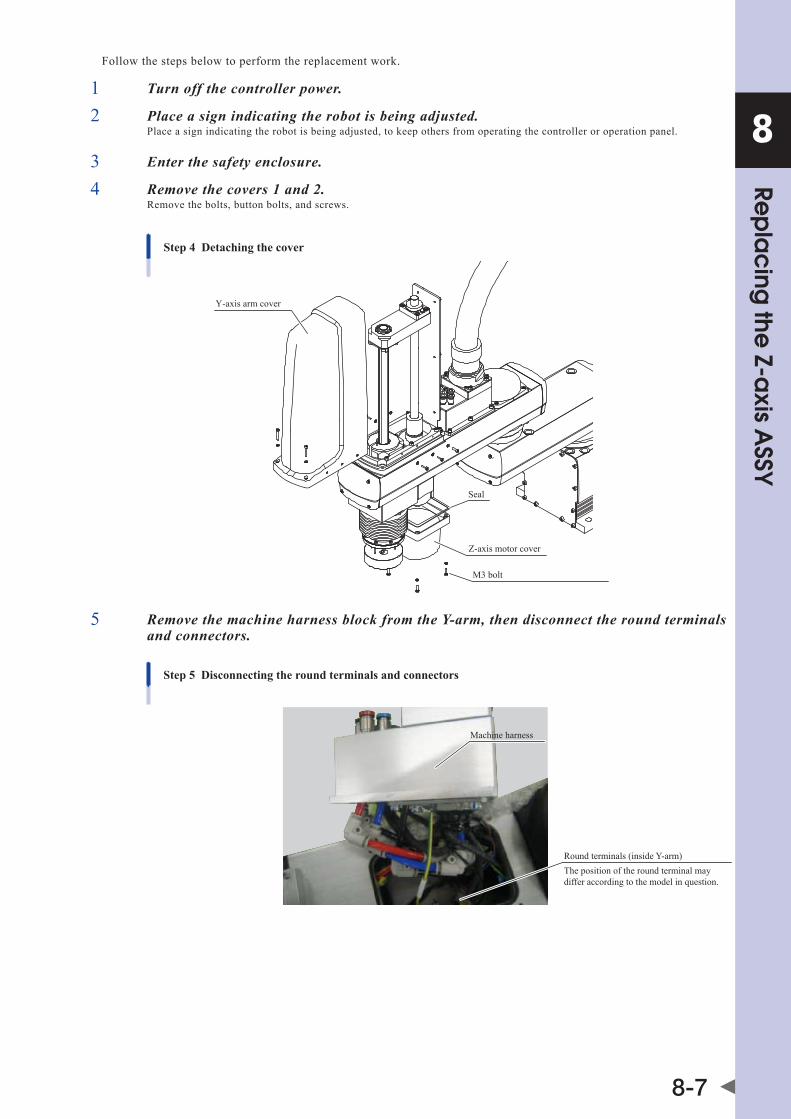
8
8-7
Rep
lac
ing the
Z-axis A
SSYFollow the steps below to perform the replacement work.
1 Turn off the controller power.
2 Place a sign indicating the robot is being adjusted.Place a sign indicating the robot is being adjusted, to keep others from operating the controller or operation panel.
3 Enter the safety enclosure.
4 Remove the covers 1 and 2.Remove the bolts, button bolts, and screws.
Step 4 Detaching the cover
Y-axis arm cover
M3 bolt
Z-axis motor cover
Seal
5 Remove the machine harness block from the Y-arm, then disconnect the round terminals and connectors.
Step 5 Disconnecting the round terminals and connectors
Machine harness
Round terminals (inside Y-arm)The position of the round terminal may differ according to the model in question.

8
8-8
Rep
lac
ing the
Z-axis A
SSY
6 Remove the ball screw ASSY and Z-axis motor.Remove the bolts, and remove the ball screw ASSY and Z-axis motor.
Step 6 Removing the ball screw ASSY and Z-axis motor
Bolt
Z-axis motor
Bolt
Ball screw ASSY
Bolt
Bolt
7 Replace with a new Z-axis assembly (with Z-axis machine reference adjusted).
8 Be sure to align the flange and motor shaft positioning marks when assembling them.
9 Reconnect the wiring at the Y-axis arm side.Restore the Y-axis arm's wiring tie band, the connector, and the round terminal as described in Chapter 6 "Replacing the machine harness".
NOTE Refer to the installation manual, Chapter 8 "1.3 Robot inner wiring diagram".
10 Move to a position outside the safety fence, then turn the controller power ON.
11 Establish an emergency stop status, then enter the safety fence area with the PB in hand.After verifying that the Z-axis is prevented from falling, release the Z-axis brake.
NOTE For the brake release procedure, refer to the "OMRON Robot Controller User's Manual".

8
8-9
Rep
lac
ing the
Z-axis A
SSY12 While raising and lowering the Z-axis, tighten bolt (3).
Apply grease to the ball screw in accordance with the instructions given in the Periodic Inspections section.
Step 7-12 Replacement and assemblyBolt (3) *Apply the screw lock.
Ball screw ASSY (2)
Bolt (6) *Apply the screw lock.Bolt (5) *Apply the screw lock.
Flange
Mark
Mark
Degrease this surface.
Motor shaft
Z-axis motor (1)
Bolt (4) *Apply the screw lock.• Gradually tighten the bolts to the specified
torque in a crisscross pattern.Two 2.5 holes are provided, but bolts are not put in these holes.
13 Turn off the controller power.
14 Reattach the covers.Reattach the covers while referring to "1. Attaching, detaching, and replacing the cover" in Chapter 2.


Chapter 9 Replacing the spline
Contents
1. Replacing the spline 9-11.1 R6YXGLC(P)250, R6YXGLC(P)350, R6YXGLC(P)400, R6YXGLC(P)500, R6YXGLC(P)600 9-1
1.2 R6YXGP500, R6YXGP600, R6YXGHP600, R6YXGP700, R6YXGP800, R6YXGP900, R6YXGP1000 9-3


9
Rep
lac
ing the
spline
9-1
1. Replacing the splineReplace the spline as shown in the Fig. below while referring to "Replacing the R-axis harmonic drive". Additionally, apply the grease to the ball spline while referring to "Periodic inspection".
CAUTION • Ifthebolttighteningtorqueisnotinstructed,seethetighteningtorquestatedin"2.Replacingtheharmonicdrive"inChapter5. • Replacingthesplinecausesapositionaldeviation.Therefore,followingasplinereplacement,anabsoluteresetmustbeperformed, andthepointdataandreferencecoordinatesmustbere-specified.
NOTE • RefertotheChapter5"2.Replacementprocedureforharmonicdrive[R-axis]". • Fordetailsabouthowtoapplythegrease,see"2.1applyingthegreasetothesplineshaft"inChapter3.
1.1 R6YXGLC(P)250, R6YXGLC(P)350, R6YXGLC(P)400, R6YXGLC(P)500, R6YXGLC(P)600
1. Replacement parts
Part Name OMRON Part No. Part No. / Specs Q'ty Remarks
1 Ball spline KCY-m1840-001 1
2 Stopper securing bolt 91312-05014 M5, length: 14 2 Replace with spare when missing (Standard type)
3 Spline nut securing bolt 91312-04012 M4, length: 12 4 Spare parts
4 Set screw 92A08-05305 M5, length: 5 1 Replace with spare when missing (Tool flange mount type)
5 Spline nut upper O-ring (outer side) 90990-17J032 Cross section diameter: 1.00mm
Inner diameter: 46.00mm 1 Becomes worn and must be replaced
6 Spline nut upper O-ring (inner side) Kn5-m181h-000 Cross section diameter: 0.80mm
Inner diameter: 33.70mm 1 Becomes worn and must be replaced
7 Spline nut securing bolt seal washer 90990-36J002 For M4 4 Becomes worn and must be replaced
8 Damper Kn3-m1788-100 1 Spare parts
2. Other tools
Name Part No. Manufacturer Remarks
Cleaning wipe
Hex wrench set
Tie band
15mm spanner
24mm spanner
Calipers, etc.
Phillips screwdriver
Screw thread locking agent Loctite 262 Henkel High strength type (red)
Harmonic grease 4B No.2 (*1) Harmonic Drive Systems Do not use grease if it was purchased 4 or more years ago. The grease has probably deteriorated.
*1 : 4.2g

9
Rep
lac
ing the
spline
9-2
■ Removal
Follow the steps below to remove the R-axis parts.
1 Turn off the controller.
2 Place a sign indicating the robot is being adjusted.Place a sign indicating the robot is being adjusted, to keep others from operating the controller or operation panel.
3 Enter the safety enclosure.
4 Using the R-axis harmonic replacement procedure, disassemble to the point where the spline is removed.
5 Remove the bolts and set screws, then remove the damper and all the other parts beneath it from the spline.
■ Replacement and reassembly
Follow the steps below to replace the spline with a new one and reassemble it.
1 Install the damper and stopper (flange) on the spline.Tighten the shaft securing bolts to the prescribed torque. Positional deviations may occur if not fully tightened.
2 Disassemble to the point where the harmonic is removed from the Y-axis arm.1. Disassemble to the point where the harmonic is removed from the Y-axis arm, even if the harmonic is not being replaced.
(Do not remove the wave generator.)
2. Wipe off the old grease from the harmonic, then apply new grease as described in Chapter 3 "2. Applying the grease".
3 Reassemble by reversing the disassembly procedure.Reassemble by reversing the disassembly procedure as described in Chapter 5 "2.1.3 Replacing the R-axis harmonic drive".
Replacing the spline
Bolt (2)
Spline (1)Spline (1)
Seal washer (7)
Bolt (3) *Apply the screw lock.Bolt (3) *Apply the screw lock.
Seal washer (7)
O-ring (5)O-ring (5)O-ring (6)
O-ring (6)
Damper (8)Damper (8)
Degrease the fastening part.
Bolt (2)
Standard type Tool flange mount type
Flat faceFlat face
Holder(Put the holder in contact with the spline shaft.)
Holder(Put the holder in contact with the spline shaft.)
Set screw (4)* Apply the screw lock.(Put the set screw in contact with the flat face.)
Set screw (4)* Apply the screw lock.(Put the set screw in contact with the flat face.)
* Screw lock: Loctite 262 (Red) (Henkel Japan) Apply a small amount of the screw lock.
* Replace the maintenance parts R13 to R17 as a set.
Degrease the fastening part.

9
Rep
lac
ing the
spline
9-3
1.2 R6YXGP500, R6YXGP600, R6YXGHP600, R6YXGP700, R6YXGP800, R6YXGP900, R6YXGP1000
1. Replacement parts
• R6YXGP500,R6YXGP600
Part Name OMRON Part No. Part No. / Specs Q'ty Remarks
1
Ball splineKbF-m1840-002 Z-axis stroke 200m 1
AssemblyKbF-m1840-102 Z-axis stroke 300m 1
Ball spline nut upper collar KbF-m1871-000 1
Endfacesealinsidespeedreduction unit KbF-m1886-000 1
2 Ball spline nut securing bolt 91312-04010 M4, length: 10 6 Must be replaced
3 Ball spline nut upper O-ring 90990-17J031 Cross section diameter: 1.00mm Inner diameter: 35.30mm 1 Becomes worn and must be replaced
4 Stopper securing bolt 91312-06018 M6, length: 18 1 Spare parts
5 Warning label 90K41-001520 1
6 Damper KbF-m1789-001 1 Spare parts
• R6YXGHP600,R6YXGP700,R6YXGP800,R6YXGP900,R6YXGP1000
Part Name OMRON Part No. Part No. / Specs Q'ty Remarks
1
Ball splineKbP-m1840-001 Z-axis stroke 200m 1
AssemblyKbP-m1840-101 Z-axis stroke 400m 1
Ball spline nut upper collar KbP-m1871-000 1
Endfacesealinsidespeedreduction unit KbP-m1886-000 For M5 1
2 Ball spline nut securing bolt 91312-05014 M5, length: 14 6 Must be replaced
3 Ball spline nut upper O-ring 90990-17J036 Cross section diameter: 1.00mm Inner diameter: 43.00mm 1 Becomes worn and must be replaced
4 Stopper securing bolt 91312-06020 M6, length: 20 1 Spare parts
5 Warning label 90K41-001520 1
6 Damper KbP-m1789-000 1 Spare parts

9
Rep
lac
ing the
spline
9-4
2. Other tools
Name Part No. Manufacturer Remarks
Cleaning wipe
Hex wrench set
Tie band
19mm spanner R6YXGP500, R6YXGP600
Hook spannerFine U-nut outer diameter: 28mm
R6YXGP500, R6YXGP600
24mm spannerR6YXGHP600, R6YXGP700, R6YXGP800, R6YXGP900, R6YXGP1000
32mm spanner
Calipers, etc.
Phillips screwdriver
Torque wrench
Screw thread locking agent Loctite 262 Henkel High strength type (red)
Harmonic grease 4B No.2 (*1) Harmonic Drive Systems Do not use grease if it was purchased 4 or more years ago. The grease has probably deteriorated.
*1: R6YXGP500, R6YXGP600:8g R6YXGHP600, R6YXGP700, R6YXGP800, R6YXGP900, R6YXGP1000:10g

9
Rep
lac
ing the
spline
9-5
■ Removal
Follow the steps below to remove the R-axis parts.
1 Turn off the controller.
2 Place a sign indicating the robot is being adjusted.Place a sign indicating the robot is being adjusted, to keep others from operating the controller or operation panel.
3 Enter the safety enclosure.
4 Remove the spline.Remove the spline as described in Chapter 5 "2.2.3 Replacing the R-axis harmonic drive"
5 Remove the damper and stopper (flange) from the spline.If the stopper bolt is covered by warning label, use a cutter to cut away the label so that the bolt head is exposed. Then remove the bolt, and remove the damper and stopper from the spline.
■ Replacement and reassembly
Follow the steps below to replace the spline with a new one and reassemble it.
1 Install the damper and stopper (flange) on the spline.Secure the stopper (flange) at its prescribed position.
2 Disassemble to the point where the harmonic is removed from the Y-axis arm.1. Disassemble to the point where the harmonic is removed from the Y-axis arm, even if the harmonic is not being replaced.
(Do not remove the wave generator.)
2. Wipe off the old grease from the harmonic, then apply new grease as described in Chapter 3 "2. Applying the grease".
3 Reassemble by reversing the disassembly procedure.Reassemble by reversing the disassembly procedure as described in Chapter 5 "2.2.3 Replacing the R-axis harmonic drive".
Replacing the spline
O-ring (3)
Spline ASSY(1)
Bolt (2) *Apply the screw lock.


Chapter 10 Motor replacement
Contents
1. Motor replacement 10-11.1 X and R axis motor replacement 10-1
1.2 Y-axis motor replacement 10-1
1.3 Z-axis motor replacement 10-3


10
Mo
tor re
pla
ce
me
nt
10-1
1. Motor replacementCAUTION • Replacingthemotorcausesapositionaldeviation.Therefore,followingamotorreplacement,anabsoluteresetmustbeperformed, andthepointdatamustbere-specified.afteranX,Y,Raxismotorreplacement,thereferencecoordinatesmustalsobere-specified. • Ifthebolttighteningtorqueisnotinstructed,seethetighteningtorquestatedin"2.Replacementprocedureforharmonicdrive"in Chapter 5.
1.1 X and R axis motor replacement
WARNING bEFoREsTaRTInGThEWoRK,ThoRoUGhLYREad“1.aTTaChInG,dETaChInG,andREPLaCInGThECovER”InChaPTER2.
For details regarding motor replacements, refer to the harmonic replacement procedure for each axis.To replace the X-axis motor, disassemble to the point where the X-axis motor is removed, then wipe the old grease from the harmonic and apply new grease as described in the harmonic replacement procedure.To replace the R-axis motor, disassemble to the step where the harmonic is removed from the Y-axis arm, then wipe the old grease from the harmonic and apply new grease as described in the harmonic replacement procedure.
CAUTION WhenreplacingtheR-axismotorasdescribedintheharmonicdrivereplacementprocedure,adeflectioncheckisrequiredforthewavegenerator of the harmonic drive which was installed in the new motor at Step 2 of the "n Replacement and reassembly" procedure. A motor-securing vise and a dial gauge are required in order to perform this check. If a vise and dial gauge are not available, the wave generator can be installed at OMRON, with the assembly then being shipped to the customer.Inthatcase,thecustomershouldorderan"additionalnewKCY-m1821-000harmonicdrive"replacementpartandrequestthat the wave generator be installed in the motor.
1. Replacement parts
Part Name OMRON Part No. Part No. / Specs Q'ty Remarks
1 X-axis motor KCY-m4880-001 1
2 R-axis motor KCY-m4883-000 1
2. Other tools
Name Part No. Manufacturer Remarks
Cleaning wipe
Hex wrench set
Phillips screwdriver
Harmonic grease 4B No.2 (*1) Harmonic Drive Systems Do not use grease if it was purchased 4 or more years ago. The grease has probably deteriorated.
*1: X-axis 25g, R-axis 4.2g
1.2 Y-axis motor replacement
WARNING bEFoREsTaRTInGThEWoRK,ThoRoUGhLYREad“1.aTTaChInG,dETaChInG,andREPLaCInGThECovER”InChaPTER2.
1. Replacement parts
Part Name OMRON Part No. Part No. / Specs Q'ty Remarks
1 Motor O-ring Kn3-m257K-000 Cross section diameter: 1.0mm Inner diameter: 29.5mm 1 Becomes worn and must be replaced
2 Motor KCY-m4881-000 1
3 Motor securing bolt 91312-04008 M4, length: 8 2 Spare parts

10
Mo
tor re
pla
ce
me
nt
10-2
2. Torque wrench, etc.
CAUTION Use accurately calibrated torque screwdrivers and torque wrenches.
Name Part No. Manufacturer Remarks
A
Torque screwdriver n30LTdK Kanon (Nakamura Mfg. Co., Ltd.)
For M3 hex socket head bolt Tightening torque: 1.8Nm (18kgfcm)
Drive bit B35, opposite side 2.5×75 vesselCo.,Inc.
Attachment hexagonal width across flat: 6.35mm Overall length: 75mm Hexagonal width across flat at tip: 2.5mm
3. Other tools
Name Part No. Manufacturer Remarks
Cleaning wipe
Hex wrench set
Harmonic grease 4B No.2 (*1) Harmonic Drive Systems Do not use grease if it was purchased 4 or more years ago. The grease has probably deteriorated.
*1 : 12g
Follow the steps below to perform the replacement work.
■ Removal
1 Turn off the controller.
2 Place a sign indicating the robot is being adjusted.Place a sign indicating the robot is being adjusted, to keep others from operating the controller or operation panel.
3 Enter the safety enclosure.
4 Remove the wave generator.Remove the wave generator as described in Chapter 5 "2. Replacing the Y-axis harmonic drive [Y-axis]".
5 Remove the motor and O-ring.Remove the motor's round terminal and the connector. Remove the bolt, then remove the motor and O-ring.
NOTE Replace the O-ring with a new one.
Y-axis motor replacement
Motor (2)
O-ring (1)
Y-axis arm
Bolt (3) Tool A

10
Mo
tor re
pla
ce
me
nt
10-3
■ Replacement and reassembly
Use the following procedure to replace the motor and reassemble the removed parts.
1 Apply new grease to the harmonic.Wipe off the old grease from the harmonic, then apply new grease as described in Chapter 5 "2. Replacing the Y-axis harmonic drive [Y-axis]".
2 Install the motor and O-ring.
CAUTION • donotallowtheo-ringtogetcaughtoutofthegrooveduringreassembly.Iftherobotisoperatedwiththeo-ringleftcaughtoutof the groove, this may cause a malfunction. • Ifforeignmatteriscaughtinduringreassemblywork,thismaycausethenoisefromtheharmonicdriveortheharmonicdriveto break.
3 Secure the round terminal.
4 Connect the motor's connector.Connect the connector as described in Chapter 6 "Replacing the machine harness".
5 Install the wave generator and the remaining parts.Install the wave generator and the remaining parts as described in Chapter 5 "2. Replacing the Y-axis harmonic drive [Y-axis]".
1.3 Z-axis motor replacementFor models R6YXGLC(P)250, R6YXGLC(P)350, R6YXGLC(P)400, R6YXGLC(P)500, R6YXGLC(P)600, replace the Z-axis motor and ball screw assembly as a set, using the procedure described in Chapter 8 "Replacing the Z-axis ASSY".


Chapter 11 Sensor replacement
Contents
1. Sensor replacement 11-11.1 X, Y-axis sensor replacement 11-1
1.2 R-axis sensor replacement 11-4

11
Senso
r rep
lac
em
ent
11-1
1. Sensor replacementCAUTION • Replacingthesensorcouldcauseapositionaldeviation.Therefore,followingasensorreplacement,itmaybenecessarytoperform anabsolutereset,andthepointdataandreferencecoordinatesmayhavetobere-specified. • Ifthebolttighteningtorqueisnotinstructed,seethetighteningtorquestatedin"2.Replacementprocedureforharmonicdrive"in Chapter 5.
1.1 X, Y-axis sensor replacement
WARNING bEFoREsTaRTInGThEWoRK,ThoRoUGhLYREad“1.aTTaChInG,dETaChInG,andREPLaCInGThECovER”InChaPTER2.
1. Replacement parts
Part Name OMRON Part No. Part No. / Specs Q'ty Remarks
1 X-axis sensor KCY-m4850-400 1
2 Y-axis sensor KCY-m4850-100 1
2. Torque wrench, etc.
CAUTION Use accurately calibrated torque screwdrivers and torque wrenches.
Name Part No. Manufacturer Remarks
A Torque wrench n190sPK13 Kanon (Nakamura Mfg. Co., Ltd.)
Width across flat: 13mm Tightening torque: 5Nm (50kgfcm)
3. Other tools
Name Part No. Manufacturer Remarks
Cleaning wipe
Spanner (wrench)
Phillips screwdriver
Follow the steps below to perform the replacement work.
■ Removal
1 Turn off the controller.
2 Place a sign indicating the robot is being adjusted.Place a sign indicating the robot is being adjusted, to keep others from operating the controller or operation panel.
3 Enter the safety enclosure.

11
Senso
r rep
lac
em
ent
11-2
Although the procedure for replacing the X-axis sensor is given here, the same procedure also applies for the Y-axis sensor.
4 Remove the base cover.Remove the cover while referring to "1. Attaching, detaching, and replacing the cover" in Chapter 2.
Removing the sensorStep 4-6
X-axis sensor (1)
NutTool ATightening torque: 5Nm (50kgfcm)
Y-axis sensor (2)
NutTool ATightening torque: 5Nm (50kgfcm)
5 Disconnect the XORG connector.
6 Remove the sensor.Remove the nut, then turn the sensor to extract it. If the sensor is difficult to turn, use the width-across-flats at the sensor's end to turn it.
■ Replacement and reassembly
Replace the sensor with a new one as described below, then reassemble by reversing the disassembly procedure.
1 While peering through the sensor mounting hole from below, rotate the X-axis arm until the dog is centered in the hole. In this condition, the X-axis arm should be slightly tilted away from the base front face.Do not rotate the X-axis arm from this position until the sensor has been temporarily secured.
2 Fit the nut over the sensor, then screw the sensor in.If the sensor is difficult to screw in, use the width-across-flats at the sensor's end. Use care to avoid damaging the sensor's screw threads. The sensor cannot be turned if the threads are damaged. Use care to avoid twisting the sensor cable. Doing so could sever the cable. Screw the sensor in until it makes contact with the dog, then back it off 1/2 a turn from that position, and temporarily secure it there with the nut. In this condition, the distance (L) between the sensor and dog should be 0.5mm.
Replacing the sensorStep 2
X-axis motor Base
Dog
X-axis sensor mounting hole
Base interior viewed from below
X-axis armY-axis arm Y-axis motor
Dog
Y-axis sensormounting hole

11
Senso
r rep
lac
em
ent
11-3
3 Connect the XORG connector.
4 Perform a machine reference adjustment.Adjust the machine reference as described in X,Y axis machine reference adjustment procedures given in Chapter 3 "2. Adjusting the origin" of the installation manual, and Chapter 4 "Adjusting the origin" of the maintenance manual for XG series standard models.
CAUTION becausethejointsarehiddenbycovers,itisdifficulttoverify the distance between the sensor and the dog. Use care to prevent the sensor from colliding with the dog.

11
Senso
r rep
lac
em
ent
11-4
1.2 R-axis sensor replacement
WARNING bEFoREsTaRTInGThEWoRK,ThoRoUGhLYREad“1.aTTaChInG,dETaChInG,andREPLaCInGThECovER”InChaPTER2.
1. Replacement parts
Part Name OMRON Part No. Part No. / Specs Q'ty Remarks
1 R-axis sensor Kdm-m4850-400 1
2 R-axis motor securing bolt 91312-05016 M5, length: 16 4 Spare parts
3 R-axis motor O-ring Kn3-m2144-000 Cross section diameter: 0.99mm Inner diameter: 53.28mm 1 Replacement required when the wire
is damaged or deteriorated.
2. Torque wrench, etc.
CAUTION Use accurately calibrated torque screwdrivers and torque wrenches.
Name Part No. Manufacturer Remarks
A Torque wrench n30sPK8 Kanon (Nakamura Mfg. Co., Ltd.)
Width across flat: 8mm Tightening torque: 1Nm (10kgfcm)
* Use a commercially available torque wrench to tighten bolts other than those shown above.
3. Other tools
Name Part No. Manufacturer Remarks
Cleaning wipe
Tie band
Spanner (wrench)
Phillips screwdriver
Follow the steps below to perform the replacement work.
■ Removal
1 Turn off the controller.
2 Place a sign indicating the robot is being adjusted.Place a sign indicating the robot is being adjusted, to keep others from operating the controller or operation panel.
3 Enter the safety enclosure.
4 Remove the Y-axis arm cover.Remove the cover while referring to "1. Attaching, detaching, and replacing the cover" in Chapter 2.
5 Cut the tie band, then disconnect the RORG connector.

11
Senso
r rep
lac
em
ent
11-5
6 Remove the R-axis motor.Remove the bolts, then remove the R-axis motor. Use care to prevent the O-ring from detaching. If it detaches, press it back into the O-ring groove. If the O-ring is damaged or in a deteriorated condition, replace it as described in the R-axis harmonic replacement procedure. Place a support beneath the motor to prevent it from falling.
Removing the R-axis motorStep 6
R-axis motor
Bolt (2)
O-ring (3)
Y-axis arm7 Remove the sensor.Remove the nut, then turn the sensor to extract it. If the sensor is difficult to turn, use the width-across-flats at the sensor's end to turn it.
Removing the R-axis sensorStep 7
R-axis sensor (1)
NutTool ATightening torque: 1Nm (10kgfcm)
Exceeding the tightening torque will damage the sensor.
■ Replacement and reassembly
Replace the sensor with a new one as described below, then reassemble by reversing the disassembly procedure.
1 While peering through the sensor mounting hole, rotate the R-axis until the dog is centered in the hole.The dog's position is offset from the hole. Use care to avoid mistaking the bolt for the dog (the dog is larger than the bolt). Do not rotate the R-axis from this position until the sensor has been temporarily secured.
Replacing the sensorStep 1
Y-axis arm
Bolt
Dog(Use care not to mistake the bolt for the dog)
R-axis sensor mounting hole
2 Fit the nut over the sensor, then screw the sensor in.If the sensor is difficult to screw in, use the width-across-flats at the sensor's end. Use care to avoid damaging the sensor's screw threads. The sensor cannot be turned if the threads are damaged. Use care to avoid twisting the sensor cable. Doing so could sever the cable. Screw the sensor in until it makes contact with the dog, then back it off 1/2 a turn from that position, and temporarily secure it there with the nut. In this condition, the distance (L) between the sensor and dog should be 0.5mm.
0.5
Replacing the R-axis sensorStep 2
Dog
Sensor

11
Senso
r rep
lac
em
ent
11-6
3 Secure the motor with the bolts.Secure the motor with the bolts, using care to avoid pinching the O-ring.
4 Connect the RORG connector.Secure the connector with a tie band as described in Chapter 6 "Replacing the machine harness".
5 Perform a machine reference adjustment.Adjust the machine reference as described in X,Y axis machine reference adjustment procedures given in Chapter 3 "2. Adjusting the origin" of the installation manual, and Chapter 4 "Adjusting the origin" of the maintenance manual for XG series standard models.
CAUTION becausethejointsarehiddenbycovers,itisdifficulttoverify the distance between the sensor and the dog. Use care to prevent the sensor from colliding with the dog.

Chapter 12 Robot cable replacement
Contents
1. Robot cable replacement 12-1


12
Rob
ot c
ab
le re
pla
ce
me
nt
12-1
1. Robot cable replacementCAUTION • anabsoluteresetisrequiredafterarobotcablereplacement. • Ifthebolttighteningtorqueisnotinstructed,seethetighteningtorquestatedin"2.Replacementprocedureforharmonicdrive"in Chapter 5.
WARNING bEFoREsTaRTInGThEWoRK,ThoRoUGhLYREad“1.aTTaChInG,dETaChInG,andREPLaCInGThECovER”InChaPTER2.
1. Replacement parts
Part Name OMRON Part No. Part No. / Specs Q'ty Remarks
1 Screw for round terminal 97602-04308 M4, Length: 8 2 Spare parts
2 Lock washer for round terminal 90172-00J040 For M4 2 Spare parts
3 Robot cable
KdP-m6211-000 1 3.5m
KdP-m6211-100 1 5m
KdP-m6211-200 1 10m
2. Other tools
Name Part No. Manufacturer Remarks
Phillips screwdriver
24mm spanner
■ Removal
Disassemble using the following procedure.
1 Turn off the controller.
2 Place a sign indicating the robot is being adjusted.Place a sign indicating the robot is being adjusted, to keep others from operating the controller or operation panel.
3 Enter the safety enclosure.
4 Remove the base cover.Remove the cover while referring to "1. Attaching, detaching, and replacing the cover" in Chapter 2.
5 Disconnect the connector.Remove the robot cable's round terminal and the connector.
Removing the connectorStep 5
Lock washer (2)
Round terminal
Screw (1)
The position of the round terminal may differ according to the model in question.
6 Disconnect the robot cable.Loosen by using a spanner at the cable clamp's width-across-flats, then disconnect the robot cable.
Removing the robot cableStep 6
Robot cable (3)
Clamp's width-across-flats: 24mmTighten securely so that the cable will not loosen.
Tighten to the point where the cable does not detach when pulled.

12
Rob
ot c
ab
le re
pla
ce
me
nt
12-2
■ Reassembly
Reassemble by reversing the disassembly procedure.
1 Tighten the lock nut and clamp.
2 Secure the round terminal and connect the connector.
NOTE Refer to Chapter 8 "1.3 Robot inner wiring diagram" of the installation manual for XG series standard models.
3 Attach the cover.

Chapter 13 Mechanical stopper replacement
Contents
1. Mechanical stopper replacement 13-11.1 X, Y-axis mechanical stoppers 13-1
1.2 Z-axis mechanical stopper 13-3
1.2.1 Upper end mechanical stopper 13-31.2.2 Lower end mechanical stopper 13-3


13
Me
cha
nica
l stop
pe
r rep
lac
em
ent
13-1
1. Mechanical stopper replacementTo ensure safety, use the following procedure to replace the mechanical stopper when it becomes damaged, deformed, or when it can no longer be properly secured. In the interest of safety, additional mechanical stoppers should also be replaced with new ones in accordance with the "additional mechanical stopper installation" procedure when they become damaged, deformed, or when they can no longer be properly secured. If damage is found at the arm or base, etc., please contact your distributor.
CAUTION If the bolt tightening torque is not instructed, see the tightening torque stated in "2. Replacement procedure for harmonic drive" in Chapter 5.
1.1 X, Y-axis mechanical stoppers
1. Replacement parts
•X-axis
Part Name OMRON Part No. Part No. / Specs Q'ty Remarks
1 Stopper damper KCY-m2197-000 1
2 Bolt 90990-01J066M10, Length: 55 Electrolessnickelplating
1
3 Nut 90189-06J106 M10 stainless 1
•Y-axis
Part Name OMRON Part No. Part No. / Specs Q'ty Remarks
1 Stopper damper KCY-m2197-000 1
Y2 Bolt 90990-01J067M10, Length: 60 Electrolessnickelplating
1
3 Nut 90189-06J106 M10 stainless 1
4 Seal washer 90990-36J010 For M10 stainless 3
2. Torque wrench, etc.
CAUTION Use accurately calibrated torque screwdrivers and torque wrenches.
Name Part No. Manufacturer Remarks
A Torque wrench n380sPK14 Kanon (Nakamura Mfg. Co., Ltd.)
Width across flat: 14mm Tightening torque: 20Nm (204kgfcm)
3. Other tools
Name Part No. Manufacturer Remarks
Hex wrench set
Spanner (wrench)

13
Me
cha
nica
l stop
pe
r rep
lac
em
ent
13-2
Follow the steps below to perform the replacement work.
■ Removal
1 Turn off the controller.
2 Place a sign indicating the robot is being adjusted.Place a sign indicating the robot is being adjusted, to keep others from operating the controller or operation panel.
3 Enter the safety enclosure.
Although the procedure for the X-axis is given here, the same procedure also applies for the Y-axis.
4 Loosen the X-axis nut, then remove the stopper damper and the bolts.
Mechanical stopper replacement
Nut (3)Tool A
M10 bolt
M10 bolt
Bolt Y2
Stopper damper (1)
Y-axis X-axis
Bolt X2
Seal washer (4)
■ Reassembly
Install the new stopper and reassemble by reversing the disassembly procedure.
1 Secure the damper between the bolt and nut.1. Secure the damper (1) between bolt (X2) and nut (3). Use the bolt and nut shown above.
2. Tighten the nut at the arm side to a torque of 42Nm (428kgf/cm). If the nut is difficult to tighten, remove the surrounding M10 bolts, then tighten the nut. Be sure to return the M10 bolts to their original positions (these are plug bolts). (For details, refer to Chapter 2 "4.1 Installing the X-axis/Y-axis additional mechanical stoppers" in the Installation Manual.) At the Y-axis, be sure to install the seal washer.
2 Verify that the movement range is restricted.
3 Go out of the safety enclosure.
4 Turn on the controller.Check that no one is inside the safety enclosure, and then turn on the controller.
CAUTION From a position outside the safety enclosure, verify that the soft limit stops the X-axis at a position before the stopper.
5 Verify that the X-axis is completely stopped.From a position outside the safety enclosure, verify that the maximum soft limit stops the X-axis at a position before the stopper.

13
Me
cha
nica
l stop
pe
r rep
lac
em
ent
13-3
1.2 Z-axis mechanical stopper
CAUTION Replacing the mechanical stopper causes a positional deviation. Therefore, following the replacement, it may be necessary to perform an absolute reset, and re-specify the point data and reference coordinates.
1.2.1 Upper end mechanical stopperReplace the damper and shaft, etc., as described in the lower bellows rotation mechanism replacement procedure.
1.2.2 Lower end mechanical stopper
1. Replacement parts
Part Name OMRON Part No. Part No. / Specs Q'ty Remarks
1 Damper KCY-m1788-000 1
In order to replace the damper, the ball screw must be detached from the motor, and this causes a ball screw centerline deviation. When a damper replacement is required, please contact your distributor.
Mechanical stopper replacement
Damper (1)
Ball screw and motor assembly


Chapter 14 Dog replacement
Contents
1. Dog replacement 14-1


14
Do
g re
pla
ce
me
nt
14-1
1. Dog replacementCAUTION
Replacing the dog causes a positional deviation. Therefore, following the replacement, an absolute reset must be performed, and the pointdataandreferencecoordinatesmustbere-specified.
Dogs are present at the X, Y, and R axes, and are detected by the origin point sensor in return-to-origin operations. The dog positions at each axis are shown below. Damaged dogs must be replaced in accordance with the harmonic replacement procedure for the robot model and axis in question.
Dog replacement
Bolt
R-axis dog
Washer
Spacer
X-axis dog (pan head)
Spacer
Y-axis dog (pan head)


Chapter 15 Bellows rotation mechanism replacement
Contents
1. Lower bellows rotation mechanism replacement 15-1
2. Upper bellows rotation mechanism replacement 15-4


15
15-1
Bellow
s rota
tion m
ec
hanism
rep
lac
em
ent
1. Lower bellows rotation mechanism replacementCAUTION • Ifthebolttighteningtorqueisnotinstructed,seethetighteningtorquestatedin"2.Replacementprocedureforharmonicdrive"in Chapter 5. • Replacingthelowerbellowsrotatingmechanismcancausepositionaldeviations. Therefore, following a sensor replacement, it may be necessary to perform an absolute reset, and the point data and reference coordinatesmayhavetobere-specified.
1. Replacement parts
Part Name OMRON Part No. Part No. / Specs Q'ty Remarks
1 Shaft Kdm-m1790-000 1
2 Damper Kn3-m1788-100 1
3 Shaft securing bolts 91312-05014 M5, length: 14 2 Spare parts
4 Set screws 92A08-05305 M5, length: 5 1 Spare parts
5 Spline lower O-ring 90200-01J112 s11.2(JIs) 1 Becomes worn and must be replaced
6 Holder securing bolts 91380-05016 M5, length: 16 stainless 1 Spare parts
7 Holder O-ring 90200-01J160 s16(JIs) 1 Becomes worn and must be replaced
8 Shaft O-ring 90990-17J025 Cross section diameter: 0.5mm Inner diameter: 15.0mm 1 Becomes worn and must be replaced
9 Circlip 99009-30700 For hole; nominal diameter: 30 1
10 Bearing 90990-25J017 6903LLB 1
11 Endfaceseal KbF-m1886-000 1Replacement required when in a deteriorated condition (dust/drip proof specs. XG(L)P only)
12 O-ring for housing Kn3-m257K-000 Cross section diameter: 1.0mm Inner diameter: 29.5mm 1 Becomes worn and must be replaced
13 Housing Kdm-m189b-000 1
14 Holder Kdm-m1791-000 1
15 Warning label 90K41-001490 1 Required only at holder replacement.
2. Other tools
Name Part No. Manufacturer Remarks
Cleaning wipe
Hex wrench set
Circlip pliers
Harmonic grease 4BNo.2 Harmonic Drive Systems
Small amount. Do not use grease if it was purchased 4 or more years ago. The grease has probably deteriorated. Other grease may also be used (dust/drip proof specs. XG(L)P only)
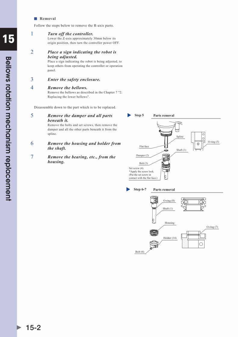
15
15-2
Bellow
s rota
tion m
ec
hanism
rep
lac
em
ent
■ Removal
Follow the steps below to remove the R-axis parts.
1 Turn off the controller.Lower the Z-axis approximately 30mm below its origin position, then turn the controller power OFF.
2 Place a sign indicating the robot is being adjusted.Place a sign indicating the robot is being adjusted, to keep others from operating the controller or operation panel.
3 Enter the safety enclosure.
4 Remove the bellows.Remove the bellows as described in the Chapter 7 "2. Replacing the lower bellows".
Disassemble down to the part which is to be replaced.
5 Remove the damper and all parts beneath it.Remove the bolts and set screws, then remove the damper and all the other parts beneath it from the spline.
Parts removalStep 5
Bolt (3)
Damper (2)
Flat face
Set screw (4)*Apply the screw lock.(Put the set screw incontact with the flat face.)
O-ring (5)
Spline
Shaft (1)
6 Remove the housing and holder from the shaft.
Parts removalStep 6-7
Bolt (6)
O-ring (7)
O-ring (8)
Housing
Shaft (1)
Holder (14)
7 Remove the bearing, etc., from the housing.

15
15-3
Bellow
s rota
tion m
ec
hanism
rep
lac
em
ent
■ Replacement and reassembly
Replace with a new part, then reassemble by reversing the disassembly procedure.
1 Affix a warning label only when the holder has been replaced.
8
Warning labelStep 1
The warning label need not completely cover the counterbore hole(because the bolt is protruding).Be sure that the warning label does not extend to the stopper's C-face.Be sure to wipe all grease from the curved face before affixing the label.
2 Apply grease to the O-ring.Use care to prevent the O-ring from being pinched.
3 Set in position.Push the shaft, housing, and holder in until they can be pushed no farther, then tighten the shaft securing bolt to its prescribed torque. Positional deviation may occur if not fully tightened.
4 Reassemble by reversing the disassembly procedure.With reference to Chapter 7 "2. Replacing the lower bellows", reassemble by reversing the disassembly procedure.
ReassemblingStep 2-3
Circlip (9)
Bearing (10)
O-ring (12)
Housing (13)
LipEnd face seal 11 (for dust/drip proof specs. only)• Apply a small amount of 4B No.2 grease to the lip.• Be sure that all the above parts are securely seated all the way around. Keep grease off the seat faces.

15
15-4
Bellow
s rota
tion m
ec
hanism
rep
lac
em
ent
2. Upper bellows rotation mechanism replacement1. Replacement parts
Part Name OMRON Part No. Part No. / Specs Q'ty Remarks
1 Shaft Kdm-m1873-000 1
2 Shaft O-ring 90990-17J078 Cross section diameter: 0.8mm Inner diameter: 13.3mm 1 Becomes worn and must be replaced
3 Nut Kdm-m1852-000 1
4 Endfaceseal KbF-m189K-000 1Replacement required when in a deteriorated condition (dust/drip proof specs. XG(L)P only)
5 Housing Kdm-m1892-000 1
6 Bearing 90990-25J018 6902LLB 1
7 Circlip 99009-30700 For hole; nominal diameter: 30 1
8 Shaft O-ring 90990-17J037 Cross section diameter: 0.5mm Inner diameter: 28.0mm 1 Becomes worn and must be replaced
2. Torque wrench, etc.
CAUTION Use accurately calibrated torque screwdrivers and torque wrenches.
Name Part No. Manufacturer Remarks
A Torque wrench n380sPK14 Kanon (Nakamura Mfg. Co., Ltd.)
Width across flat: 14mm Tightening torque 20Nm (204kgfcm)
3. Other tools
Name Part No. Manufacturer Remarks
Cleaning wipe
Circlip pliers
Harmonic grease 4BNo.2 Harmonic Drive Systems Small amount. Do not use grease if it was purchased 4 or more years ago. The grease has probably deteriorated.
■ Removal
Follow the steps below to remove the R-axis parts.
1 Turn off the controller.
2 Place a sign indicating the robot is being adjusted.Place a sign indicating the robot is being adjusted, to keep others from operating the controller or operation panel.
3 Enter the safety enclosure.
4 Remove the bellows.Remove the bellows as described in the Chapter 7 "1. Replacing the upper bellows".
Disassemble down to the part which is to be replaced.
5 Remove the nut, then remove the housing from the shaft.
Parts removalStep 5
Nut (3)
Width across flat: 35mm
Housing
O-ring (2)
Shaft (1)
Tool AWidth across flat: 14mm

15
15-5
Bellow
s rota
tion m
ec
hanism
rep
lac
em
ent
6 Remove the bearing, etc., from the housing.
ReassemblingStep 6
Bearing (6)
Lip
Circlip (7)
Housing (5) O-ring (8)
End face seal 4 (for dust/drip proof specs. only)• Apply a small amount of 4B No.2 grease to the lip.• Be sure that all the above parts are securely seated all the way around. Keep grease off the seat faces.
■ Replacement and reassembly
Replace with a new part, then reassemble by reversing the disassembly procedure.
1 Apply grease to the O-ring.Use care to prevent the O-ring from being pinched.
2 Set in position.Push the shaft, housing, and nut in until they can be pushed no farther, then tighten the nut to its prescribed torque.
3 Reassemble by reversing the disassembly procedure.With reference to Chapter 7 "1. Replacing the upper bellows", reassemble by reversing the disassembly procedure.


Chapter 16 End face seal replacement
Contents
1. End face seal replacement 16-11.1 Replacing the X-axis end face seal (only on dust/drip proof specification models XG(L)P) 16-1
1.2 Replacing the Y-axis end face seal (only on dust/drip proof specification models XG(L)P) 16-2
1.3 Replacing the R-axis end face seal 16-3


16
End fa
ce
sea
l rep
lac
em
ent
16-1
1. End face seal replacementCAUTION
Replacing the end face seal causes a positional deviation. Therefore, following the replacement, an absolute reset must be performed, andthepointdataandreferencecoordinatesmustbere-specified.
The X,Y axis end face seal is present only on dust/drip proof specification models (XG(L)P) in order to keep water and dust out of the joint area. The R-axis end face seal prevents harmonic grease from leaking to the spline side. These seals must be replaced when in a deteriorated condition.
1.1 Replacing the X-axis end face seal (only on dust/drip proof specification models XG(L)P)
1. Replacement parts
Part Name OMRON Part No. Part No. / Specs Q'ty Remarks
1 Endfaceseal Kdm-m2111-000 1 (Dust/drip proof specs. XG(L)P only)
2. Other tools
Name Part No. Manufacturer Remarks
Harmonic grease 4B No.2 (*1) Harmonic Drive Systems Do not use grease if it was purchased 4 or more years ago. The grease has probably deteriorated.
*1: 25g
■ Removal
Disassemble using the following procedure.
1 Turn off the controller.
2 Place a sign indicating the robot is being adjusted.Place a sign indicating the robot is being adjusted, to keep others from operating the controller or operation panel.
3 Enter the safety enclosure.
4 Refer to the Chapter 5 "2. Replacement procedure for harmonic drive [X-axis]", then disassemble to the step where the end face seal is removed.
■ Reassembly
Reassemble by reversing the disassembly procedure.
1 Reassemble from the point where the new end face seal is installed in the holder.
2 Apply new grease to the harmonic.Refer to the Chapter 5 "2. Replacement procedure for harmonic drive [X-axis]", then wipe the old grease from the harmonic and apply new grease.

16
End fa
ce
sea
l rep
lac
em
ent
16-2
1.2 Replacing the Y-axis end face seal (only on dust/drip proof specification models XG(L)P)
1. Replacement parts
Part Name OMRON Part No. Part No. / Specs Q'ty Remarks
1 Endfaceseal Kdm-m2511-000 1 (Dust/drip proof specs. XG(L)P only)
2. Other tools
Name Part No. Manufacturer Remarks
Harmonic grease 4B No.2 (*1) Harmonic Drive Systems Do not use grease if it was purchased 4 or more years ago. The grease has probably deteriorated.
*1: 12g
■ Removal
Disassemble using the following procedure.
1 Turn off the controller.
2 Place a sign indicating the robot is being adjusted.Place a sign indicating the robot is being adjusted, to keep others from operating the controller or operation panel.
3 Enter the safety enclosure.
4 Refer to the Chapter 5 "2. Replacement procedure for harmonic drive [Y-axis]", then disassemble to the step where the end face seal is removed.
■ Reassembly
Reassemble by reversing the disassembly procedure.
1 Reassemble from the point where the new end face seal is installed in the holder.
2 Apply new grease to the harmonic.Refer to the Chapter 5 "2. Replacement procedure for harmonic drive [Y-axis]", then wipe the old grease from the harmonic and apply new grease.

16
End fa
ce
sea
l rep
lac
em
ent
16-3
1.3 Replacing the R-axis end face seal
1. Replacement parts
Part Name OMRON Part No. Part No. / Specs Q'ty Remarks
1 Endfaceseal(*1) KCY-m1886-000 1
*1: A new end face seal will be subjected to a high level of friction if sufficient R-axis aging has not occurred. Therefore, be sure to perform R-axis aging, and do not replace this seal unless it is damaged.
2. Other tools
Name Part No. Manufacturer Remarks
Harmonic grease 4B No.2 (*1) Harmonic Drive Systems Do not use grease if it was purchased 4 or more years ago. The grease has probably deteriorated.
*1: 4.2g
■ Removal
Disassemble using the following procedure.
1 Turn off the controller.
2 Place a sign indicating the robot is being adjusted.Place a sign indicating the robot is being adjusted, to keep others from operating the controller or operation panel.
3 Enter the safety enclosure.
4 Refer to the Chapter 5 "2. Replacement procedure for harmonic drive [R-axis]", then disassemble to the step where the end face seal is removed.
5 Remove the end face seal from the shaft.
Replacing the end face sealEnd face seal (1)• Apply a small amount of 4B No.2 grease to the lip, taking care that no grease remains on the lip's inner side. Grease on the lip's inner side could cause grease to leak from the spline.• Be sure that the seal is securely seated (all around) on its seat. There must be no grease on the seating face.
Lip
Shaft
16
End fa
ce
sea
l rep
lac
em
ent
16-4
■ Reassembly
Reassemble by reversing the disassembly procedure.
1 Install a new end face seal on the shaft.
2 Install the harmonic on the shaft.
3 Apply new grease to the harmonic.Refer to the Chapter 5 "2. Replacement procedure for harmonic drive [R-axis]", then wipe the old grease from the harmonic and apply new grease.
CAUTION A new end face seal will be subjected to a high level of friction due to contact with the harmonic input area, and an overload error could thereforeoccurifsufficientR-axisaginghasnotoccurred.besuretoperformsufficientaging.

Chapter 17 Maintenance parts
Contents
1. Maintenance parts 17-11.1 Standard type 17-1
1.2 Tool flange mount type 17-4
2. Consumable parts 17-7
3. Basic specification 17-8


17
Ma
intena
nce
pa
rts
17-1
1. Maintenance parts1.1 Standard type
No. Part No. Part name Q’ty Remarks Recommended replacement timing
X-axis
X1 KCY-m2110-001 haRmonICdRIvEassY. 1 Speed reduction unit See "2." in Chapter 5 of installation manual for XG.
X2 KCY-m4880-001 MOTOR ASSY.,1 1 MotorX3 KCY-m4850-400 PROXIMITY SW. ASSY 1 SensorX4 98502-03030 sCREW,PanhEad 1 Nut for dogX5 Kn3-m2143-000 O RING,2 1 O-ring for motor matingX6 Kdm-m2134-000 sPaCER 1 Spacer for dogX7 91312-03030 boLT,hEX.soCKEThEad 11 Arm side mounting bolt of speed reduction unitX8 91312-03020 boLT,hEX.soCKEThEad 16 Base side mounting bolt of speed reduction unitX9 90200-01J900 O-RING 1 Outer O-ring of speed reduction unit
X10 Kdm-m2111-000 sEaL 1 Jointendfaceseal(XGPandXGLPonly)X11 90990-17J021 O-RING 1 O-ring for lower bolt of harness block
X12 90990-36J008 WashERsEaL 28Speed reduction unit mounting bolt, lower bolt of harness block, seal washer for user wiring connector bolt
X13 91312-03018 boLT,hEX.soCKEThEad 4 Lower bolt of harness blockX14 Kdm-m1151-000 sEaL 2 Lower seal of base plateX15 Kdm-m1315-000 sEaL 2 Seal for base front and rear coversX16 91312-05014 boLT,hEX.soCKEThEad 4 Bolt for base plateX17 Kn4-m257K-000 O RING,1 1 Upper O-ring of speed reduction unitX18 KCY-m2197-000 damPER,2 2 Mechanical stopper damperX19 90990-01J066 boLT,hEX.soCKEThEad 2 Mechanical stopper boltX20 90189-00J106 nUT,hEXaGon 2 Nut for mechanical stopper boltX21 90200-01J900 O-RING 1 Outer O-ring for arm side of speed reduction unit
Y-axis
Y1 Kn4-m1896-000 O RING,2 1 Lower O-ring of speed reduction unitY2 90200-01J800 O-RING 1 Outer O-ring for arm side of speed reduction unit
Y3 KCY-m2510-001 haRmononICdRIvEassY. 1 Speed reduction unit See "2." in Chapter 5 of installation manual for XG.
Y4 KCY-m4881-000 aCsERvomoToR 1 MotorY5 KCY-m4850-100 PROXIMITY SW. ASSY. 1 SensorY6 KCY-m2197-000 damPER,2 1 Mechanical stopper damperY7 90189-00J106 nUT,hEXaGon 1 Nut for mechanical stopper boltY8 91312-04008 boLT,hEX.soCKEThEad 2 Motor mounting boltY9 Kn3-m257K-000 O RING,1 1 O-ring for motor mating
Y10 KCY-m1314-001 CovER,4 1 Y-axis cover
Y11Kdm-m1567-000
sEaL1 Upper seal of lower Y-axis arm cover
(R6YXGLC(P)250 to R6YXGLC(P)400)
Kdm-m1567-100 1 Upper seal of lower Y-axis arm cover (R6YXGLC(P)500, R6YXGLC(P)600)
Y12 91312-03030 boLT,hEX.soCKEThEad 11 Mounting bolt on X-axis arm side of speed reduction unitY13 Kdm-m2511-000 sEaL 1 Jointendfaceseal(XGPandXGLPonly)Y14 90200-01J800 O-RING 1 Outer O-ring of speed reduction unitY15 90990-36J010 WashERsEaL 3 Seal washer for mechanical stopper bolt
Y16 90990-36J008 WashERsEaL 23
Seal washer for Y-axis arm side mounting bolt of speed reduction unit, lower mounting screw of Y-axis cover, mounting bolt of parts around harness block
Y17 98980-03012 sCREW,bIndInGhEad 4 Lower mounting screw of Y-axis coverY18 Kdm-m2534-000 sPaCER 1 Spacer for dogY19 98502-03030 sCREW,PanhEad 1 Nut for dog
Y20Kdm-m1568-000
sEaL1 Lower seal for lower Y-axis arm cover
(R6YXGLC(P)250 to R6YXGLC(P)400)
Kdm-m1568-100 1 Lower seal for lower Y-axis arm cover (R6YXGLC(P)500, R6YXGLC(P)600)
Y21 91312-03022 boLT,hEX.soCKEThEad 15 Y-axis arm side mounting bolt of speed reduction unitY22 Kdm-m1327-000 sEaL 1 Lower seal for harness block
Y23 91380-03018 boLT,hEX.soCKEThEad 8 Mounting bolt of harness block and parts around harness block
Y24 Kdm-m1328-000 sEaL 1 Inner seal for parts around harness blockY25 Kdm-m1329-000 sEaL 1 Outer seal for parts around harness blockY26 90990-01J067 boLT,hEX.soCKEThEad 1 Mechanical stopper bolt
Z-axis
Z1 KCY-m4882-001 MOTOR ASSY.,3 1 Motor
These parts need to be replaced as a set.
Z2 91312-04012 boLT,hEX.soCKEThEad 2 Motor mounting boltZ3 KCY-m1753-000 COUPLING 1 CouplingZ4 KCY-m1750-000 sCREW,baLL 1 Ball screwZ5 KCY-m1744-000 PLaTE 1 Bearing outer ring holding plateZ6 KaI-m2273-000 bEaRInG 1 Ball screw support bearingZ7 KCY-m1788-000 damPER,1 1 Lower end damperZ8 90112-2aJ010 boLT,hEX.soCKEThEad 8 Bolt for outer ring holding plateZ9 KCY-m1778-000 sLEEvE,LoCK1 1 Bearing inner ring holding plate
Z10 KCY-m1712-000 hoLdER 1 Bearing housingZ11 91312-03014 boLThEX.soCKEThEad 4 Ball screw mounting boltZ12 91312-04014 boLT,hEX.soCKEThEad 4 Z-axis ASSY mounting boltZ13 90933-01J002 bEaRInG 2 Upper bearing of ball spline shaftZ14 Kn3-m1788-100 damPER,1 1 Upper end damperZ15 KCY-m1780-001 sToPPER,1 1 Upper end stopper

17
Ma
intena
nce
pa
rts
17-2
No. Part No. Part name Q’ty Remarks Recommended replacement timing
R-axis
R1 KCY-m1821-000 haRmonICdRIvEassY. 1 Speed reduction unit See "2." in Chapter 5 of installation manual for XG.
R2 Kn3-m1895-000 O RING 1 Lower O-ring of speed reduction unitR3 91312-03022 boLT,hEX.soCKEThEad 8 Speed reduction unit mounting boltR4 90990-17J034 O-RING 1 O-ring for input part of speed reduction unitR5 90990-36J008 WashERsEaL 12 Seal washer for speed reduction unit mounting boltR6 91312-03014 boLT,hEX.soCKEThEad 12 Speed reduction unit mounting boltR7 Kdm-m1888-000 DOG,R 1 Nut for dogR8 90990-28J064 WashER,PLaIn 1 Washer for upper dog of speed reduction unitR9 KCY-m4883-000 MOTOR ASSY.,3 1 Motor
R10 91312-05016 boLThEX.soCKEThEad 4 Motor mounting boltR11 Kn3-m2144-000 O RING,3 1 Lower O-ring of motorR12 Kdm-m4850-400 PROXIMITY SW. ASSY. 1 SensorR13 KCY-m1840-001 sPLInE,baLL 1 Ball spline
These parts need to be replaced as a set.
R14 90990-17J032 O-RING 1 Upper O-ring of ball spline nut (outside)R15 Kn5-m181h-000 O RING,4 1 Upper O-ring of ball spline nut (inside)R16 90990-36J002 WashER,sEaL 4 Seal washer for ball spline nut mounting boltR17 91312-04012 boLT,hEX.soCKEThEad 4 Ball spline nut mounting boltR18 KCY-m1886-000 sEaL 1 EndfacesealinsidespeedreductionunitR19 KCY-m1872-000 SHAFT 1 Spine extension shaftR20 91312-03010 boLT,hEX.soCKEThEad 4 Spline extension shaft mounting boltR21 Kdm-m1897-000 bELLoWs 1 Lower bellowsR22 Kdm-m1898-000 damPER 1 Upper rubber for lower bellowsR23 Kdm-m1790-000 SHAFT 1 Spline lower portion extension shaftR24 91312-05014 boLT,hEX.soCKEThEad 2 Spline lower portion extension shaft mounting boltR25 90990-25J017 bEaRInG 1 Bearing for lower bellowsR26 99009-30700 CIRCLIP 1 Circlip for bearing for lower bellowsR27 Kdm-m189J-000 damPER 1 Lower rubber for lower bellowsR28 KbF-m1886-000 sEaL 1 Endfacesealforlowerbellows(XGPandXGLPonly)R29 90200-01J350 O-RING 2 O-ring for lower portion of lower bellows
R30 90990-17J025 O-RING 2 O-ring for bearing inner ring for upper and lower bellows of extension shaft at upper portion of spline
R31 90200-01J160 O-RING 1 O-ring for holding of bearing inner ring for lower bellowsR32 90200-01J500 O-RING 2 O-ring for upper portion of lower bellowsR33 90200-01J112 O-RING 1 Lower O-ring of splineR34 Kn3-m257K-000 O RING,1 1 O-ring for bearing outer ring for lower bellowsR35 92A08-05305 sCREW,sET 1 Spline lower portion extension shaft mounting set screwR36 90990-25J018 bEaRInG 1 Bearing for upper bellowsR37 99009-28700 CIRCLIP 1 Circlip for bearing for upper bellowsR38 Kdm-m1899-000 bELLoWs 1 Upper bellowsR39 Kdm-m189J-000 damPER 2 Rubber for upper bellowsR40 90990-17J078 O-RING 1 Shaft O-ringR41 90990-17J037 O-RING 1 O-ring for bearing outer ring for upper bellowsR42 90200-01J350 O-RING 2 O-ring for upper portion of upper bellowsR43 Kdm-m189K-000 sEaL 1 Endfacesealforupperbellows(XGPandXGLPonly)R44 Kn4-m2159-000 O,RING 3 1 Upper O-ring for lower holder of Y-axis arm
Cables
C1
Kdm-m4843-001
haRnEss,maChInE2
1 Machine harness (R6YXGLP250) Kdm-m4843-101 1 Machine harness (R6YXGLP350) Kdm-m4843-201 1 Machine harness (R6YXGLP400) Kdm-m4843-301 1 Machine harness (R6YXGLP500) Kdm-m4843-401 1 Machine harness (R6YXGLP600) Kdm-m4843-501 1 Machine harness (R6YXGLC250) Kdm-m4843-601 1 Machine harness (R6YXGLC350) Kdm-m4843-701 1 Machine harness (R6YXGLC400) Kdm-m4843-801 1 Machine harness (R6YXGLC500) Kdm-m4843-901 1 Machine harness (R6YXGLC600)
C2 Kdm-m4874-000 ConnECToRE/L4 1 Connector for user wiring on base side
C3 Kdm-m4872-000 ConnECToRE/L2 1 Connector for user wiring on base side supplied with robot
C4KdP-m6211-000
CabLE,RoboT1 Robot cable (3.5m)
KdP-m6211-100 1 Robot cable (5m)KdP-m6211-200 1 Robot cable (10m)
C5 Kdm-m4871-000 ConnECToRE/L1 1 Connector for user wiring on Y-axis arm side supplied with robot
C6 Kdm-m4873-000 ConnECToRE/L3 1 Connector for user wiring on Y-axis arm side

17
Ma
intena
nce
pa
rts
17-3
Standard type
X19
X18
X5 (inside)
X1,X9,X10 (inside)
X7,X17,X21 (inside)
X4,X6 (inside)
Y1 (inside)Y5,Y18,Y19 (inside)
Y22,Y23,Y24,Y25 (inside)
Y4,Y8 (inside)
Y9,Y16,Y17,Y21
R44 (inside)
X15 (inside)
X2 (inside)
X11,X12,X13,X14,X16 (inside)
X15 (inside)
X20 (inside)
Y12 (inside)
X3 (inside)
X8,X12 (inside)R23
R21
R22
R19,R20 (inside)
R36,R37,R40,R41,R42,R43 (inside)R39
R39
R38
R9,R10,R11 (inside)
Y2,Y3,Y13,Y14 (inside)
Z1 to Z12 (inside)
Y6Y26
R30 (inside)
Z13 (inside)
R13 (inside)
R12 (inside)
Y20 (inside)
Y11 (inside)
R24 (inside)
R32 (inside)
R25,R26,R28,R29,R30,R31,R33,R34,R35 (inside)
R1,R2,R3,R4,R5,R6,R7,R8,R18 (inside)
R14,R15,R16,R17 (inside)
C1
C6
Y15Y7
C5
C4
C3
X12,C2

17
Ma
intena
nce
pa
rts
17-4
1.2 Tool flange mount type
No. Part No. Part name Q’ty Remarks Recommended replacement timing
X-axis
X1 KCY-m2110-001 haRmonICdRIvEassY. 1 Speed reduction unit See "2." in Chapter 5 of installation manual for XG.
X2 KCY-m4880-001 MOTOR ASSY.,1 1 MotorX3 KCY-m4850-400 PROXIMITY SW. ASSY 1 SensorX4 98502-03030 sCREW,PanhEad 1 Nut for dogX5 Kn3-m2143-000 O RING,2 1 O-ring for motor matingX6 Kdm-m2134-000 sPaCER 1 Spacer for dogX7 91312-03030 boLT,hEX.soCKEThEad 11 Arm side mounting bolt of speed reduction unitX8 91312-03020 boLT,hEX.soCKEThEad 16 Base side mounting bolt of speed reduction unitX9 90200-01J900 O-RING 1 Outer O-ring of speed reduction unit
X10 Kdm-m2111-000 sEaL 1 Jointendfaceseal(XGPandXGLPonly)X11 90990-17J021 O-RING 1 O-ring for lower bolt of harness block
X12 90990-36J008 WashERsEaL 28Speed reduction unit mounting bolt, lower bolt of harness block, seal washer for user wiring connector bolt
X13 91312-03018 boLT,hEX.soCKEThEad 4 Lower bolt of harness blockX14 Kdm-m1151-000 sEaL 2 Lower seal of base plateX15 Kdm-m1315-000 sEaL 2 Seal for base front and rear coversX16 91312-05014 boLT,hEX.soCKEThEad 4 Bolt for base plateX17 Kn4-m257K-000 O RING,1 1 Upper O-ring of speed reduction unitX18 KCY-m2197-000 damPER,2 2 Mechanical stopper damperX19 90990-01J066 boLT,hEX.soCKEThEad 2 Mechanical stopper boltX20 90189-00J106 nUT,hEXaGon 2 Nut for mechanical stopper boltX21 90200-01J900 O-RING 1 Outer O-ring for arm side of speed reduction unit
Y-axis
Y1 Kn4-m1896-000 O RING,2 1 Lower O-ring of speed reduction unitY2 90200-01J800 O-RING 1 Outer O-ring for arm side of speed reduction unit
Y3 KCY-m2510-001 haRmonICdRIvEassY. 1 Speed reduction unit See "2." in Chapter 5 of installation manual for XG.
Y4 KCY-m4881-000 aCsERvomoToR 1 MotorY5 KCY-m4850-100 PROXIMITY SW. ASSY. 1 SensorY6 KCY-m2197-000 damPER,2 1 Mechanical stopper damperY7 90189-00J106 nUT,hEXaGon 1 Nut for mechanical stopper boltY8 91312-04008 boLT,hEX.soCKEThEad 2 Motor mounting boltY9 Kn3-m257K-000 O RING,1 1 O-ring for motor mating
Y10 KCY-m1314-001 CovER,4 1 Y-axis cover
Y11Kdm-m1567-000
sEaL1 Upper seal of lower Y-axis arm cover
(R6YXGLC(P)250 to R6YXGLC(P)400)
Kdm-m1567-100 1 Upper seal of lower Y-axis arm cover (R6YXGLC(P)500, R6YXGLC(P)600)
Y12 91312-03030 boLT,hEX.soCKEThEad 11 Mounting bolt on X-axis arm side of speed reduction unitY13 Kdm-m2511-000 sEaL 1 Jointendfaceseal(XGPandXGLPonly)Y14 90200-01J800 O-RING 1 Outer O-ring of speed reduction unitY15 90990-36J010 WashERsEaL 3 Seal washer for mechanical stopper bolt
Y16 90990-36J008 WashERsEaL 23
Seal washer for Y-axis arm side mounting bolt of speed reduction unit, lower mounting screw of Y-axis cover, mounting bolt of parts around harness block
Y17 98980-03012 sCREW,bIndInGhEad 4 Lower mounting screw of Y-axis coverY18 Kdm-m2534-000 sPaCER 1 Spacer for dogY19 98502-03030 sCREW,PanhEad 1 Nut for dog
Y20Kdm-m1568-000
sEaL1 Lower seal for lower Y-axis arm cover
(R6YXGLC(P)250 to R6YXGLC(P)400)
Kdm-m1568-100 1 Lower seal for lower Y-axis arm cover (R6YXGLC(P)500, R6YXGLC(P)600)
Y21 91312-03022 boLT,hEX.soCKEThEad 15 Y-axis arm side mounting bolt of speed reduction unitY22 Kdm-m1327-000 sEaL 1 Lower seal for harness block
Y23 91380-03018 boLT,hEX.soCKEThEad 8Mounting bolt of harness block and parts around harness block
Y24 Kdm-m1328-000 sEaL 1 Inner seal for parts around harness blockY25 Kdm-m1329-000 sEaL 1 Outer seal for parts around harness blockY26 90990-01J067 boLT,hEX.soCKEThEad 1 Mechanical stopper bolt
Z-axis
Z1 KCY-m4882-001 MOTOR ASSY.,3 1 Motor
These parts need to be replaced as a set.
Z2 91312-04012 boLT,hEX.soCKEThEad 2 Motor mounting boltZ3 KCY-m1753-000 COUPLING 1 CouplingZ4 KCY-m1750-000 sCREW,baLL 1 Ball screwZ5 KCY-m1744-000 PLaTE 1 Bearing outer ring holding plateZ6 KaI-m2273-000 bEaRInG 1 Ball screw support bearingZ7 KCY-m1788-000 damPER,1 1 Lower end damperZ8 90112-2aJ010 boLT,hEX.soCKEThEad 8 Bolt for outer ring holding plateZ9 KCY-m1778-000 sLEEvE,LoCK1 1 Bearing inner ring holding plate
Z10 KCY-m1712-000 hoLdER 1 Bearing housingZ11 91312-03014 boLThEX.soCKEThEad 4 Ball screw mounting boltZ12 91312-04014 boLT,hEX.soCKEThEad 4 Z-axis ASSY mounting boltZ13 90933-01J002 bEaRInG 2 Upper bearing of ball spline shaftZ15 KCY-m1790-000 SHAFT 1 Tool flangeZ16 91312-05014 boLThEX.soCKEThEad 2 Tool flange mounting boltZ17 92A08-05308 sCREW,sET 1 Tool flange mounting set screw

17
Ma
intena
nce
pa
rts
17-5
No. Part No. Part name Q’ty Remarks Recommended replacement timing
R-axis
R1 KCY-m1821-000 haRmonICdRIvEassY. 1 Speed reduction unit See "2." in Chapter 5 of installation manual for XG.
R2 Kn3-m1895-000 O RING 1 Lower O-ring of speed reduction unitR3 91312-03022 boLT,hEX.soCKEThEad 8 Speed reduction unit mounting boltR4 90990-17J034 O-RING 1 O-ring for input part of speed reduction unitR5 90990-36J008 WashERsEaL 12 Seal washer for speed reduction unit mounting boltR6 91312-03014 boLT,hEX.soCKEThEad 12 Speed reduction unit mounting boltR7 Kdm-m1888-000 DOG,R 1 Nut for dogR8 90990-28J064 WashER,PLaIn 1 Washer for upper dog of speed reduction unitR9 KCY-m4883-000 MOTOR ASSY.,3 1 Motor
R10 91312-05016 boLThEX.soCKEThEad 4 Motor mounting boltR11 Kn3-m2144-000 O RING,3 1 Lower O-ring of motorR12 Kdm-m4850-400 PROXIMITY SW. ASSY. 1 SensorR13 KCY-m1840-001 sPLInE,baLL 1 Ball spline
These parts need to be replaced as a set.
R14 90990-17J032 O-RING 1 Upper O-ring of ball spline nut (outside)R15 Kn5-m181h-000 O RING,4 1 Upper O-ring of ball spline nut (inside)R16 90990-36J002 WashER,sEaL 4 Seal washer for ball spline nut mounting boltR17 91312-04012 boLT,hEX.soCKEThEad 4 Ball spline nut mounting boltR18 KCY-m1886-000 sEaL 1 EndfacesealinsidespeedreductionunitR19 KCY-m1872-000 SHAFT 1 Spine extension shaftR20 91312-03010 boLT,hEX.soCKEThEad 4 Spline extension shaft mounting boltR21 Kdm-m1897-000 bELLoWs 1 Lower bellowsR22 Kdm-m1898-000 damPER 1 Upper rubber for lower bellowsR23 Kdm-m1790-000 SHAFT 1 Spline lower portion extension shaftR24 91312-05014 boLT,hEX.soCKEThEad 2 Spline lower portion extension shaft mounting boltR25 90990-25J017 bEaRInG 1 Bearing for lower bellowsR26 99009-30700 CIRCLIP 1 Circlip for bearing for lower bellowsR27 Kdm-m189J-000 damPER 1 Lower rubber for lower bellowsR28 KbF-m1886-000 sEaL 1 Endfacesealforlowerbellows(XGPandXGLPonly)R29 90200-01J350 O-RING 2 O-ring for lower portion of lower bellows
R30 90990-17J025 O-RING 2 O-ring for bearing inner ring for upper and lower bellows of extension shaft at upper portion of spline
R31 90200-01J160 O-RING 1 O-ring for holding of bearing inner ring for lower bellowsR32 90200-01J500 O-RING 2 O-ring for upper portion of lower bellowsR33 90200-01J112 O-RING 1 Lower O-ring of splineR34 Kn3-m257K-000 O RING,1 1 O-ring for bearing outer ring for lower bellowsR35 92A08-05305 sCREW,sET 1 Spline lower portion extension shaft mounting set screwR36 90990-25J018 bEaRInG 1 Bearing for upper bellowsR37 99009-28700 CIRCLIP 1 Circlip for bearing for upper bellowsR38 Kdm-m1899-000 bELLoWs 1 Upper bellowsR39 Kdm-m189J-000 damPER 2 Rubber for upper bellowsR40 90990-17J078 O-RING 1 Shaft O-ringR41 90990-17J037 O-RING 1 O-ring for bearing outer ring for upper bellowsR42 90200-01J350 O-RING 2 O-ring for upper portion of upper bellowsR43 Kdm-m189K-000 sEaL 1 Endfacesealforupperbellows(XGPandXGLPonly)R44 Kn4-m2159-000 O,RING 3 1 Upper O-ring for lower holder of Y-axis arm
Cables
C1
Kdm-m4843-001
haRnEss,maChInE2
1 Machine harness (R6YXGLP250) Kdm-m4843-101 1 Machine harness (R6YXGLP350) Kdm-m4843-201 1 Machine harness (R6YXGLP400) Kdm-m4843-301 1 Machine harness (R6YXGLP500) Kdm-m4843-401 1 Machine harness (R6YXGLP600) Kdm-m4843-501 1 Machine harness (R6YXGLC250) Kdm-m4843-601 1 Machine harness (R6YXGLC350) Kdm-m4843-701 1 Machine harness (R6YXGLC400) Kdm-m4843-801 1 Machine harness (R6YXGLC500) Kdm-m4843-901 1 Machine harness (R6YXGLC600)
C2 Kdm-m4874-000 ConnECToRE/L4 1 Connector for user wiring on base side
C3 Kdm-m4872-000 ConnECToRE/L2 1 Connector for user wiring on base side supplied with robot
C4KdP-m6211-000
CabLE,RoboT1 Robot cable (3.5m)
KdP-m6211-100 1 Robot cable (5m)KdP-m6211-200 1 Robot cable (10m)
C5 Kdm-m4871-000 ConnECToRE/L1 1 Connector for user wiring on Y-axis arm side supplied with robot
C6 Kdm-m4873-000 ConnECToRE/L3 1 Connector for user wiring on Y-axis arm side

17
Ma
intena
nce
pa
rts
17-6
Tool flange mount type
(Only the pars different from those of the standard type are shown.)
Z17Z15
Z16

17
Ma
intena
nce
pa
rts
17-7
2. Consumable partsNOTE
For details about consumable part locations, see "1. Maintenance parts" in this chapter.
Machine harness
Robot model Consumable part Q'ty Remarks
R6YXGLP250 Kdm-m4843-000 1 Machine harness
R6YXGLP350 Kdm-m4843-100 1 Machine harness
R6YXGLP400 Kdm-m4843-200 1 Machine harness
R6YXGLP500 Kdm-m4843-300 1 Machine harness
R6YXGLP600 Kdm-m4843-400 1 Machine harness
R6YXGLC250 Kdm-m4843-500 1 Machine harness
R6YXGLC350 Kdm-m4843-600 1 Machine harness
R6YXGLC400 Kdm-m4843-700 1 Machine harness
R6YXGLC500 Kdm-m4843-800 1 Machine harness
R6YXGLC600 Kdm-m4843-900 1 Machine harness
R6YXGP500 Kdn-m4843-000 1 Machine harness
R6YXGP600 Kdn-m4843-100 2 Machine harness
R6YXGHP600 KdP-m4843-000 3 Machine harness
R6YXGP700 KdP-m4843-100 4 Machine harness
R6YXGP800 KdP-m4843-200 5 Machine harness
R6YXGP900 KdP-m4843-300 6 Machine harness
R6YXGP1000 KdP-m4843-400 7 Machine harness
Bellows
Robot model Stroke Consumable part Q'ty Remarks
R6YXGLC250, R6YXGLC350, R6YXGLC400, R6YXGLC500, R6YXGLC600
Kdm-m1899-000 1 Upper bellows
R6YXGLP250, R6YXGLP350, R6YXGLP400, R6YXGLP500, R6YXGLP600
Kdm-m1897-100 1 Lower bellows
R6YXGP500, R6YXGP600, R6YXGHP600, R6YXGP700, R6YXGP800
200 KdP-m1899-00x 1
R6YXGP500, R6YXGP600 300 KdP-m1899-10x 1
R6YXGHP600, R6YXGP700, R6YXGP800, R6YXGP900, R6YXGP1000
400 KdP-m1899-20x 1

17
Ma
intena
nce
pa
rts
17-8
3. Basic specification
Robot model R6YXGLC(P)250 R6YXGLC(P)350 R6YXGLC(P)400 R6YXGLC(P)500 R6YXGLC(P)600
Axis specifications
X-axisArm length 100mm 200mm 250mm 250mm 350mm
Rotation angle ±129°
Y-axisArm length 150mm 250mm
Rotation angle ±134° ±144°
Z-axis Stroke 150mm
R-axis Rotation angle ±360°
Motor
X-axis 200W
Y-axis 150W
Z-axis 50W
R-axis 100W
Maximum speed
XY resultant 4.5m/s 5.6m/s 6.1m/s 5.1m/s 4.9m/s
Z-axis 1.1m/s
R-axis 1020°/s
Repeatability (*1)
XY-axes ±0.01mm
Z-axis ±0.01mm
R-axis ±0.004°
Payload 4kg
R-axis tolerable moment of inertia (*2) 0.05kgm2 (0.5kgfcms2)
User wiring 10 cables
User tubing 4×4
Travel limit 1.Soft limit 2.Mechanical stopper (XYZ-axes)
Robot cable 3.5m (option: 5m, 10m)
Weight 21.5kg 22kg 22.5kg 25kg 26kg
Degree of cleanliness (R6YXG(L)C) Class ISO 3 (ISO14644-1), Suction air flow 30N /min. (*3)
Dust/drip proof protection rating (R6YXG(L)P)
IP65(IEC60529)oritsequivalent(*4)
*1: At constant ambient temperature (XY) *2: There are limits to acceleration coefficient settings. *3: Class10(0.1μm)FEd-sTd-209doritsequivalent The required suction air flow may vary depending on the operating conditions or environment. *4: Do not splash the jet flow onto the bellows directly. For details about drip proof performance for fluid other than water, contact your distributor.
* Thez-axissplinemayvibrateinaz-axisoperationspeedrangeof20%to40%dependingonthearmpositionorz-axisposition.Ifthez-axissplinevibrates, operate it beyond this operation speed range.
Noise level
Equivalentsoundlevelofrobot,Laeq(a) (when there is 10dB or larger difference from the back ground sound pressure level)
Position where the noise level is measured
75.1dB1.25m apart from the back of the robot, 1.6m height from the floor surface.
Note: The noise level can be higher when the robot is set nearby the objects that cause sound reflection.

17
Ma
intena
nce
pa
rts
17-9
Robot model R6YXGP500 R6YXGP600
Axis specifications
X-axisArm length 200mm 300mm
Rotation angle ±130°
Y-axisArm length 300mm
Rotation angle ±145°
Z-axis Stroke 200mm/300mm
R-axis Rotation angle ±360°
Motor
X-axis 400W
Y-axis 200W
Z-axis 200W
R-axis 200W
Maximum speed
XY resultant 7.6m/sec 8.4m/sec
Z-axis 2.3m/sec(200st), 1.7m/sec(300st)
R-axis 1700°/sec
Repeatability (*1)
XY-axes ±0.01mm
Z-axis ±0.01mm
R-axis ±0.004°
Payload 8kg
R-axis tolerable moment of inertia (*2) 0.30kgm2
User wiring 20 cables
User tubing 6×3
Travel limit 1.Soft limit 2.Mechanical stopper (XYZ-axes)
Robot cable 3.5m (option: 5m, 10m)
Weight 33kg 34kg
Dust/drip proof protection rating (R6YXG(L)P) IP65(IEC60529)oritsequivalent(*3)
*1: At constant ambient temperature (XY-axes) *2: There are limits to acceleration coefficient settings. *3: Do not splash the jet flow onto the bellows directly. For details about drip proof performance for fluid other than water, contact your distributor.
Noise level
Equivalentsoundlevelofrobot,Laeq(a) (when there is 10dB or larger difference from the back ground sound pressure level)
Position where the noise level is measured
76.2dB1.25m apart from the back of the robot, 1.6m height from the floor surface.

17
Ma
intena
nce
pa
rts
17-10
Robot model R6YXGHP600 R6YXGP700 R6YXGP800 R6YXGP900 R6YXGP1000
Axis specifications
X-axisArm length 200mm 300mm 400mm 500mm 600mm
Rotation angle ±130°
Y-axisArm length 400mm
Rotation angle ±150°
Z-axis Stroke 200mm/400mm
R-axis Rotation angle ±360°
Motor
X-axis 750W
Y-axis 400W
Z-axis 400W
R-axis 200W
Maximum speed
XY resultant 7.7m/sec 8.4m/sec 9.2m/sec 9.9m/sec 10.6m/sec
Z-axis 2.3m/sec(200st), 1.7m/sec(400st)
R-axis 920°/sec
Repeatability (*1)
XY-axes ±0.02mm
Z-axis ±0.01mm
R-axis ±0.004°
Payload 18kg
R-axis tolerable moment of inertia (*2) 1.0kgm2
User wiring 20 cables
User tubing 6×3
Travel limit 1.Soft limit 2.Mechanical stopper (XYZ-axes)
Robot cable 3.5m (option: 5m, 10m)
Weight 52kg, 54kg 54kg, 56kg 56kg, 58kg 58kg, 60kg 60kg, 62kg
Dust/drip proof protection rating (R6YXG(L)P) IP65(IEC60529)oritsequivalent(*3)
*1: At constant ambient temperature (XY-axes) *2: There are limits to acceleration coefficient settings. *3: Do not splash the jet flow onto the bellows directly. For details about drip proof performance for fluid other than water, contact your distributor.
Noise level
Equivalentsoundlevelofrobot,Laeq(a) (when there is 10dB or larger difference from the back ground sound pressure level)
Position where the noise level is measured
78.4dB1.0m apart from the back of the robot, 1.6m height from the floor surface.


Revision history
amanualrevisioncodeappearsasasuffixtothecatalognumberonthefrontcovermanual.
Cat. No. I159E-EN-01
Revision code
The following table outlines the changes made to the manual during each revision.
Revision code Date Description
01 October 2013 Original production


Cat. No. I159E-EN-01 Note: Specifications subject to change without notice.
Authorized Distributor:
Printed in Europe


