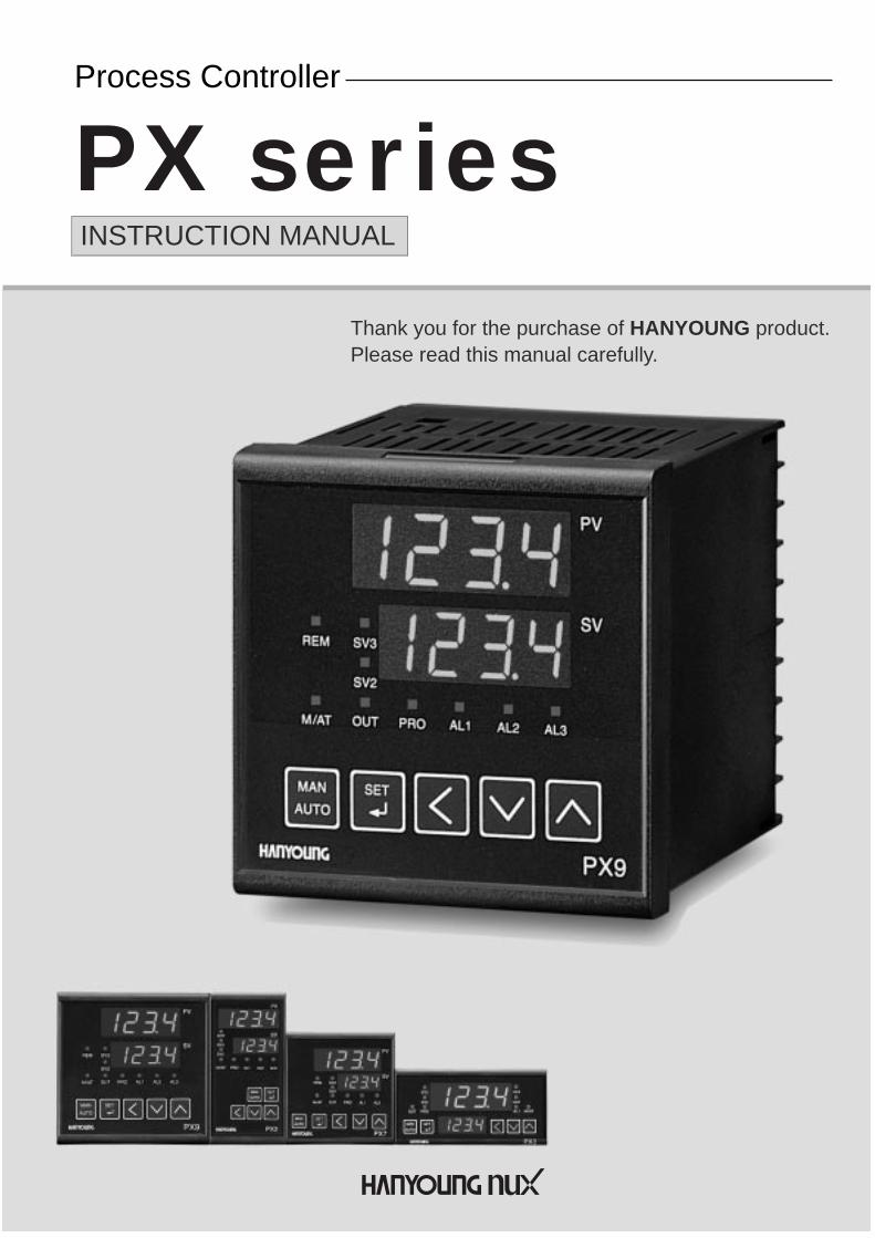
PX seriesINSTRUCTION MANUAL
Thank you for the purchase of HANYOUNG product.Please read this manual carefully.
Process Controller
Contents
2
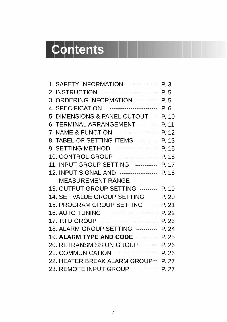
1. SAFETY INFORMATION2. INSTRUCTION 3. ORDERING INFORMATION4. SPECIFICATION5. DIMENSIONS & PANEL CUTOUT6. TERMINAL ARRANGEMENT7. NAME & FUNCTION8. TABEL OF SETTING ITEMS9. SETTING METHOD10. CONTROL GROUP11. INPUT GROUP SETTING12. INPUT SIGNAL AND
MEASUREMENT RANGE13. OUTPUT GROUP SETTING14. SET VALUE GROUP SETTING15. PROGRAM GROUP SETTING16. AUTO TUNING17. P.I.D GROUP18. ALARM GROUP SETTING19. ALARM TYPE AND CODE20. RETRANSMISSION GROUP21. COMMUNICATION22. HEATER BREAK ALARM GROUP23. REMOTE INPUT GROUP
P. 3P. 5P. 5P. 6P. 10P. 11P. 12P. 13P. 15P. 16P. 17P. 18
P. 19P. 20P. 21P. 22P. 23P. 24P. 25P. 26P. 26P. 27P. 27
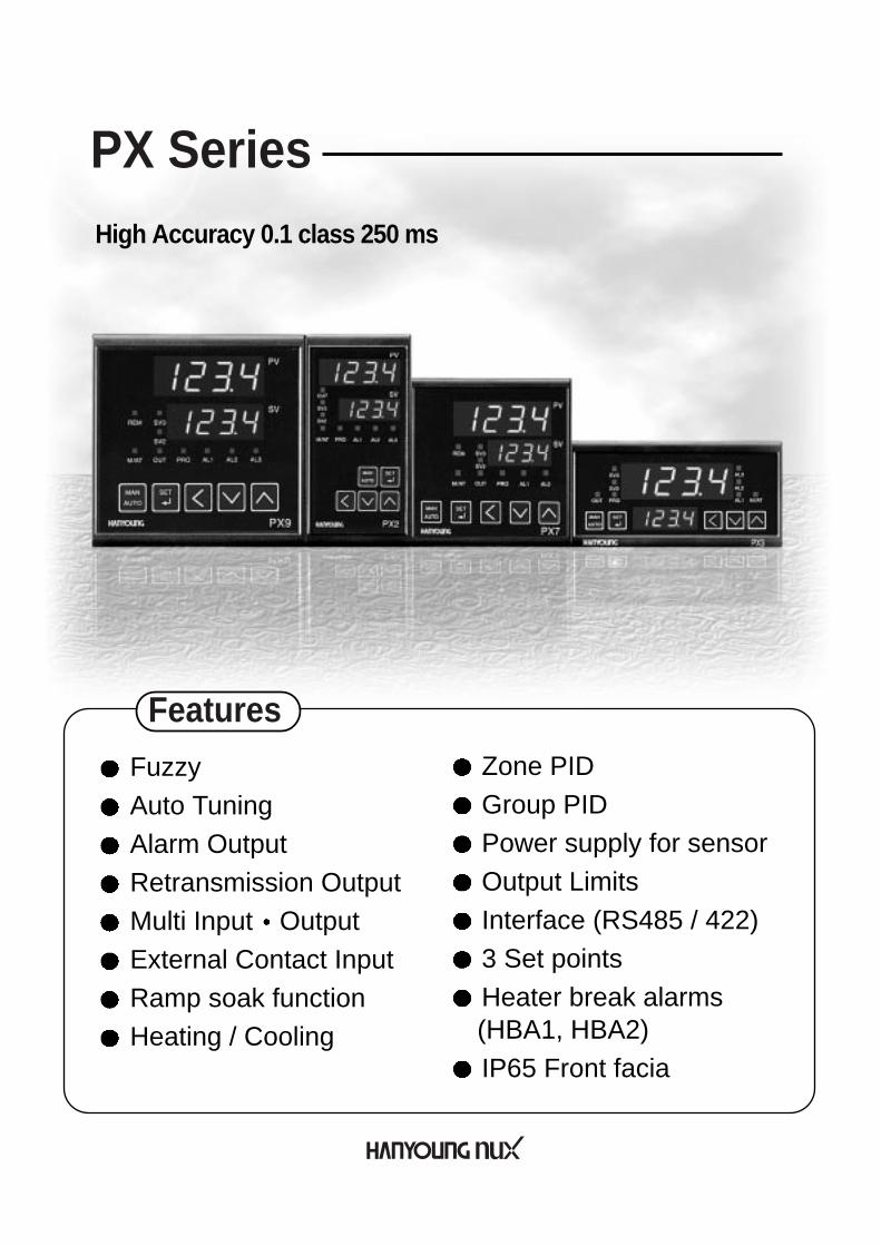
Fuzzy Auto TuningAlarm OutputRetransmission Output Multi Input OutputExternal Contact InputRamp soak functionHeating / Cooling
Zone PID Group PID Power supply for sensorOutput LimitsInterface (RS485 / 422)3 Set pointsHeater break alarms (HBA1, HBA2)IP65 Front facia
High Accuracy 0.1 class 250 ms
Features
PX Series

Before using, please read this (SAFETY INFORMATION) and then use this controller. It is important that the instructions in this manual are followed when using this instrument.Please keep this manual for future reference.Precautions are classified in WARNING and CAUTION.
WARNING1. Caution on wiring
Use an external protection circuit if a fault in the control loop could possibly lead to a seriousproblem.This instrument do not have a switch for power and a fuse, so please set them if it is needed. (Fuse rating 250 V, 0.5 A)
2. Power supply Use a rated voltage to prevent damage or trouble.To avoid electrical shock or damage, do not turn ON the power until the wiring is completed.
3. Prohibit use in gas atmosphereDo not use it at a place exposed to combustible or explosive gas.
4. Handling of unitTo avoid malfunction, electrical shock or fire, this unit must not be disassembled or repaired.Do not touch the terminals to avoid electrical shock or malfunction.
5. Caution on maintenanceTurn OFF the power before mounting or removing the instrument.To ensure continuous and safe operation of the instrument, periodical maintenance isrecommended. Some parts are limited in life.The warranty period is 1 year only if using in the correct way.
CAUTION1. Caution on handling Do not install the instrument under any of the following conditions.
The ambient temperature exceeds 0 ~ 50 The ambient humidity exceeds 45 ~ 85 % RH.A place where temperature changes suddenly or icing occurs.A place exposed to corrosive gas or combustible gas.Vibration or shock is likely to be transmitted to the instrument.A place exposed to water, oil, chemicals, steam, sunlight.A place exposed to much dust, salt or iron.A place with much inductive disturbance, static electricity, magnetism noise.A place where heat such as radiant heat stays.
4
WARNING
CAUTION
There is a possibility of death or heavy injury when handling in wrong way.
There is a possibility of injury or physical damage when handling in wrong way.
SAFETY INFORMATION1

5
2. InstallationAttach the brackets (2 units) on the fixed halls and tighten with a screwdriver. Fixing torque is about 147 N. cm (1.5 kg.cm)(Care should be taken not to tighten forcedly)
3. Caution on terminal connectionsTo avoid induction noise to input wires seperate from the power and output wires.Keep input wires away from output wires and use shielded wires to earth.Use a compensating cable with thermocouple.For R.T.D input use a cable which is a small lead wire resistance and without resistancedifference to 3 wires.If the wiring has noise, use the following step: connect a surge absorber to the conductor coilside if the conductors are connected to the load output, such as the relay contact output. (EX. For 220 V AC ENC 471D-05A)Use an insulating transformer with a noise filter when the power suppy has much noise. (EX. TDK brand ZMB 22R5-11 noise filter) Noise filter should be mounted on a panel which has been earthed and the wiring between thenoise filter output and the instrument power terminals should be shorten.It is effective to use a twisted cable for power supply against noise.The heater power supply and the instrument power supply should be connected using thesame power suppy when a heater break alarm.Time for preparation of contact output is required at power ON. When the output signal is usedfor an extenal interlock circuit, connect a delay relay.
4. For load circuit connectionUse an extra relay when the frequency of operation is rather high. SSR output type isrecommended.Electromagnetic switch : Proportional cycle time is Min. 30 secSSR : Proportional cycle time is Min. 1 sec Contact output life : Mechanical : 10 million times (no load)
Electrical : 100 thousand times (rated load)SSR drive pulse voltage, 4 ~ 20 mA DC are not insulated with internal circuit. Use non-grounded sensor to R.T.D and thermocouple.
5. For waterproof (Waterproof type)The instrument has IP65. Use rubber packing when installing the instrument to panel. Please attach the rubber in correct way.
6. Caution on key operation / troubleIf alarm function is not set correctly, alarm output can not be operated at a trouble point. Be sure to check the alarm operation. If the input cable is disconnected, the display shows “ ”.When replacing the sensor, please turn OFF the power suppy.
7. Other Do not use organic solvents such as alcohol, benzine when cleaning. (Use neutral detergent)
6
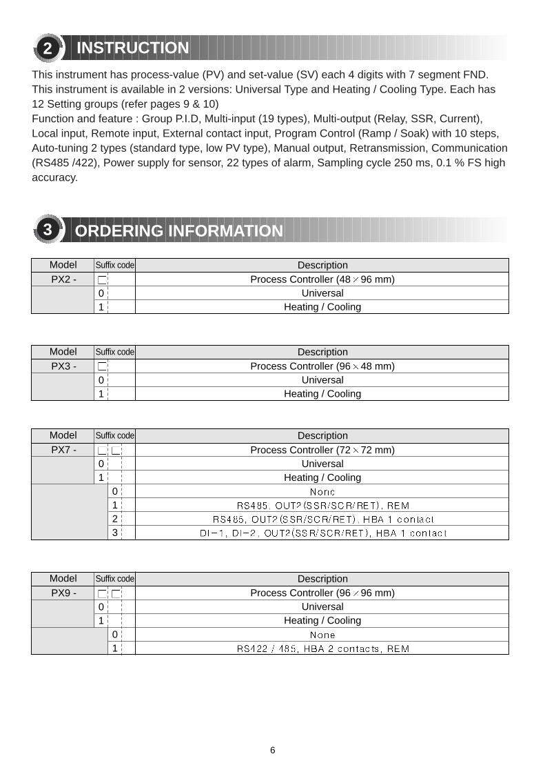
This instrument has process-value (PV) and set-value (SV) each 4 digits with 7 segment FND.This instrument is available in 2 versions: Universal Type and Heating / Cooling Type. Each has12 Setting groups (refer pages 9 & 10) Function and feature : Group P.I.D, Multi-input (19 types), Multi-output (Relay, SSR, Current),Local input, Remote input, External contact input, Program Control (Ramp / Soak) with 10 steps,Auto-tuning 2 types (standard type, low PV type), Manual output, Retransmission, Communication(RS485 /422), Power supply for sensor, 22 types of alarm, Sampling cycle 250 ms, 0.1 % FS highaccuracy.
ORDERING INFORMATION
INSTRUCTION2
3
PX2 - Process Controller (48 96 mm)Universal
Heating / Cooling01
DescriptionSuffix codeModel
PX3 - Process Controller (96 48 mm)Universal
Heating / Cooling01
DescriptionSuffix codeModel
PX9 - Process Controller (96 96 mm)Universal
Heating / Cooling01
01
DescriptionSuffix codeModel
PX7 - Process Controller (72 72 mm)Universal
Heating / Cooling01
0123
DescriptionSuffix codeModel

7
INPUT
Input
Sampling cycle timeInput resolution
Input impedance
Allowable signal sourceresistance
Allowable wiringresistance
Allowable input voltage
Noise ratio
StandardStandard junction
temperaturecompensation tolerance
Burn-out detection
Accuracy
Thermocouple, R.T.D, Direct voltage ( refer to the input signal and measurement range on page 18 )250 mSBelow decimal point of rangeThermocouple / Voltage (mV) input : 1 or aboveVoltage input ( V ) : Approx. 1 Thermocouple : 250 or belowVoltage input : 2 or below
R.T.D : 150 or below / 1 wire
Thermocouple, R.T.D, Direct voltage (mV) : 10 VDirect voltage (V) : 20 VNMRR :40 dB or aboveCMRR :120 dB or above ( 50/60 Hz 1 %)Thermocouple / R.T.D ( KS / IEC / DIN )
1.5 ( 15 ~ 35 ), 2.0 ( 15 ~ 50 )
OFF, Up / Down scale selectable Thermocouple burn-out : Up / Down scaleR.T.D burn-out : Up scale(TC / R.T.D burn-out detection current : Approx. 50 )0.1 % of F.S
SPECIFICATION4
100 - 240 V ~, 24 V50/60 Hz-10 % +10 %Max. 6.0 W, 10 VA or below
27 V - 20 mA ( but, it is not available when using retransmission output )
20 min. (at 500 V DC)Between primary terminal and secondary terminalBetween primary terminal and ground Between ground and secondary terminal2300 V AC 50/60 Hz for 1 minuteBetween primary terminal and secondary terminal Between primary terminal and ground Between F.G and secondary terminal : 1500 V AC 50/60 Hz for 1 minute
Power supply voltageFrequency
Voltage variationPower consumption
Power supply forsensor
Insulation resistance
Dielectric strength
POWER SUPPLY
8
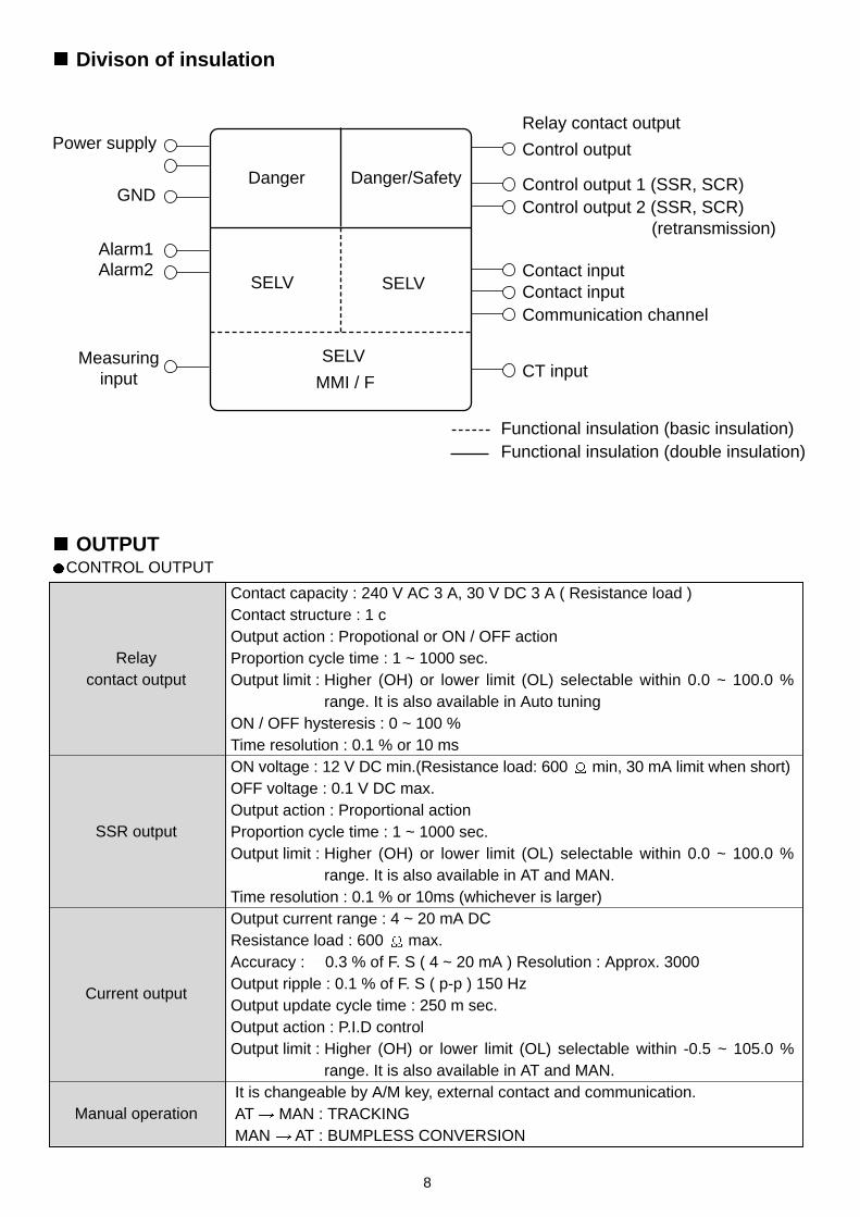
SELV
Danger Danger/Safety
SELV
SELV
MMI / F
Power supply
GND
Alarm1Alarm2
Control output
Relay contact output
Control output 1 (SSR, SCR)Control output 2 (SSR, SCR)
Contact inputContact inputCommunication channel
CT input
(retransmission)
Measuringinput
Divison of insulation
Functional insulation (basic insulation)Functional insulation (double insulation)
OUTPUTCONTROL OUTPUT
Relay contact output
SSR output
Current output
Manual operation
Contact capacity : 240 V AC 3 A, 30 V DC 3 A ( Resistance load )Contact structure : 1 cOutput action : Propotional or ON / OFF actionProportion cycle time : 1 ~ 1000 sec.Output limit : Higher (OH) or lower limit (OL) selectable within 0.0 ~ 100.0 %
range. It is also available in Auto tuningON / OFF hysteresis : 0 ~ 100 %Time resolution : 0.1 % or 10 ms ON voltage : 12 V DC min.(Resistance load: 600 min, 30 mA limit when short) OFF voltage : 0.1 V DC max. Output action : Proportional actionProportion cycle time : 1 ~ 1000 sec. Output limit : Higher (OH) or lower limit (OL) selectable within 0.0 ~ 100.0 %
range. It is also available in AT and MAN.Time resolution : 0.1 % or 10ms (whichever is larger)Output current range : 4 ~ 20 mA DCResistance load : 600 max. Accuracy : 0.3 % of F. S ( 4 ~ 20 mA ) Resolution : Approx. 3000Output ripple : 0.1 % of F. S ( p-p ) 150 Hz Output update cycle time : 250 m sec.Output action : P.I.D control Output limit : Higher (OH) or lower limit (OL) selectable within -0.5 ~ 105.0 %
range. It is also available in AT and MAN.It is changeable by A/M key, external contact and communication.AT MAN : TRACKINGMAN AT : BUMPLESS CONVERSION

9
RETRANSMISSION OUTPUT
Current output
Output current range : 4 ~ 20 mA DC, Resistance load : 600 max. Accuracy : 0.3 % of F. S (4 ~ 20 mA), Resolution : Approx. 3000 Output ripple : 0.1 % of F. S (p-p), 150 HzOutput update cycle time : 500 msec (When remote option)
ALARM OUTPUT ( HBA COMMON )
Alarm outputOutput : Relay contact, Output contact : 3 pointsContact capacity : 240 V AC 1 A , 30 V DC 1 A (Resistance load) Contact structure : 1 a
COMMUNICATION INTERFACE
CommunicationInterface
Standard : EIA RS485 Number of devices (Max.) : 31, Address setting : 1~99 range Communication type : 2-wire or 4-wire half-duplexSynchronization : Asynchronous Communication order : None Communication distance : Max. 1200 m Communication rate : 600, 1200, 2400, 4800, 9600 Start Bit : 1Bit, Data length : 7 or 8 Bit, Parity : None, Even, Odd Stop Bit : 1 or 2 Bit, Protocol : PC LINKResponse time : Handling time + ( RP.T 10 ms )
HEATER BREAK ALARM
Heater break alarm
Output contact : 2 points Current measurement range : 1 ~ 50 A AC
(Resolution 0.5 A, 5 % of F.S 1 Digit)Alarm output : AL1, 2 output It is available to use in ON / OFF or proportional action.(not available in current or cooling output)Minimum detection time : 0.2 sec, Dead Band : 0 ~ 100 %
SAFETY AND EMC STANDARDS
Safety and EMCStandards
Safety standards: IEC1010-1-1990 and EN61010-1-1992; CSA1010 CAT (IEC1010-1); and UL508.
EMC Standards: EN55011 Class A, Group 1, for emission (EMS); andEN50082-2-1995 for immunity(EMI). The indicator continuously operates within a measuringaccuracy of 20 % of the range. EN61000-3-2, EN61000-3-3
Ambience
Installation Conditions(for normal operation)
Ambient temperature : 0 ~ 50 Ambient humidity : 20 ~ 90 % RH (No condensation) Installation place : Indoors, Magnetic effect : 400 AT/m max.Vibration : 5 ~ 14 Hz, forth width 1.2 mm max.
4 ~ 150 Hz, 4.9 (0.5 G) max. Shock : 147 (15 G), 11 msec max., Height : 2000 m max.Installation category : (EN61010-1), Pollution degree : (EN61010-1) Storage temperature : -25 ~ 70 , Storage humidity : 5 ~ 95 % RHCase : Plastic Weight : PX2 (342 g), PX3 (340 g), PX7 (344 g), PX9 (472 g)
Including brackets (Brackets 40 g)
10
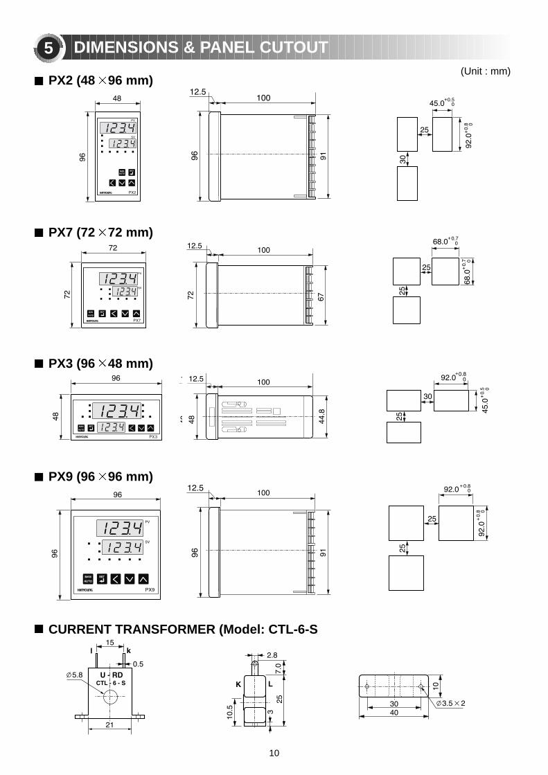
DIMENSIONS & PANEL CUTOUT5(Unit : mm)
PX2 (48 96 mm)
PX7 (72 72 mm)
PX3 (96 48 mm)
PX9 (96 96 mm)
CURRENT TRANSFORMER (Model: CTL-6-S

11
TERMINAL ARRANGEMENT6
Note] Heater break alarm is used in option 2,3 by setting alarm outputs (AL1,AL2)
[Note] Heater break alarm is used by setting alarm outputs (AL1,AL2,AL3)
Optional Optional 1 Optional 2 Optional 3
PX9 (96 96 mm)
PX2 (48 96 mm) PX3 (96 48 mm)
PX7 (72 72 mm)

Functions
FunctionsDisplays the process temperature value.Displays various set - value, message, and parameter.Lights when the remote operation.Lights when the SV2 or SV3 is displayed.This lamp lights when Manual control.(It does not light for AT)Lights when the control output is ON.Lights during program operation.Lights when the alarm 1 operates.Lights when the alarm 2 operates.Lights when the alarm 3 operates.
Used to select Auto or Manual control.
Used to change from the operation mode to the setting mode, to selectparameters, and to register set-value. Press this key for 3 sec to display settingmode, set-value, and process value.
Used to select digit for changing.
Used to decrease set-values and to select setting mode.
Used to increase set-values and to select setting mode.
Name of respective partsProcess-value (PV)Set-value (SV)Remote indicator
Set-value display indicator Manual /Auto tuning indicatorOutput indicatorProgram display indicatorAlarm 1 indicatorAlarm 2 indicatorAlarm 3 indicator
Key
NAME & FUNCTION
12
7
Front
Displays
Control keys
13
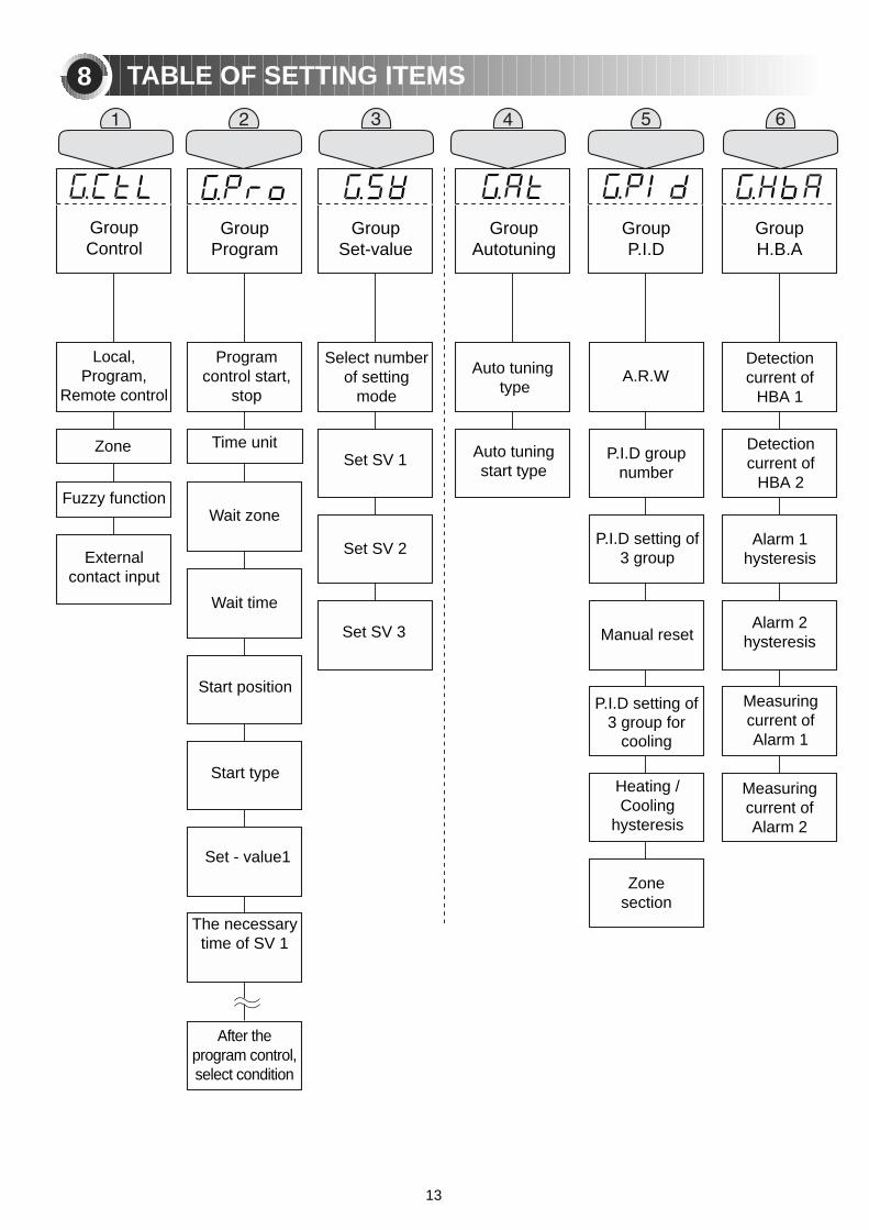
TABLE OF SETTING ITEMS8
GroupControl
Local,Program,
Remote control
Zone
Fuzzy function
Externalcontact input
Programcontrol start,
stop
Time unit
Wait zone
Wait time
Start position
Start type
Set - value1
The necessarytime of SV 1
After theprogram control,select condition
A.R.W
P.I.D groupnumber
P.I.D setting of3 group
Manual reset
P.I.D setting of3 group for
cooling
Heating / Cooling
hysteresis
Zonesection
Detectioncurrent of
HBA 1
Detectioncurrent of
HBA 2
Alarm 1hysteresis
Alarm 2hysteresis
Measuringcurrent ofAlarm 1
Measuringcurrent ofAlarm 2
Select numberof setting
mode
Set SV 1
Set SV 2
Set SV 3
Auto tuningtype
Auto tuningstart type
GroupProgram
GroupSet-value
GroupAutotuning
GroupP.I.D
GroupH.B.A

14
Cycle time ofuniversal orheating sidein heating /cooling type
Alarm functiontype of alarm
output
Dead band ofalarm output
Alarm valueof alarmoutput
Retransmissionoutput or power
supply for sensor
High limit ofretransmission
Low limit ofretransmission
High limit ofremote input
Low limit ofremote input
High limit ofscale
Low limit ofscale
PV filter time
PV compensation
Burn-outdirection
Output type
Reverse /Direct action
Input type
Maximumrange
Minimumrange
Decimal point
Maximum on scale
Minimum on scale
PV filter
PV Bias
Protocol RS485/422
Communication rate (B.P.S)
Parity check
Stop bit
Data length
Address
Response time
GroupAlarm
GroupRetransmission
GroupCommunication
GroupRemote
GroupOutput
GroupInput
Cycle time ofcooling side in
heating /cooling type
Hysteresis
Output volume when input
disconnection( output 1 )
Output volume when input
disconnection( output 2 )
Maximumvalue of output
Minimum value of output
Setting and Display level selectThis controller has 3 different levels of setting, thereby restrictingoperator access if so desired. The following describes theselevels :
Level 1 select : Access available to setting and displaying only up Group #3 (Group set value)
Level 2 select : Access available to setting and displaying only up Group #8 (Group communication)
Level 3 select : Access available to setting and displaying of allGroups.
/

SETTING METHOD
15
9
Display shift
AFTER COMPLETION OF WIRING, APPLY POWER ONProduction Model Code will be indicated as in below, followed by current PV and SV values,as in below.For setting a level, press and at a time for 3 sec. to enter (LEVEL) setting mode. (Level 3 is set at the factory) In the condition, press for 3 sec to enter (display) selection mode. (This mode is limited by level setting mode ) In the conditon, press to set manual output value regardless auto operation data and press to indicate an auto output value.
3 SecAuto
outputvalue
display
Manual output setting and display
or
Heating/Cooling
Universal 3 Sec
3 Sec
After checking wiring,power ON.
Set the whole setting afterselect "3" as below.After finishing, select "1" toprevent an error in setting.
Make display range to be sameas level setting range so thatnot to be shown other displaygroup which is not needed.
Control group setting display.Press or key to shift toeach group.
If press key in the controlgroup, control mode will beshown.
Press3sec
Ban theuse of thismodebecausethis isspecialmode.

16
GROUP SETTING10
FunctionsExternal input signalDIS selection
Initial ValueDisplay conditionOperationNameSignal
Control group display
control mode selection
Zone selection 1
Fuzzy function selection
External contact inputselection
Set a control mode
LOCA / PROG / REM
OFF / ON
OFF / ON
( Refer to chart 1 )OFF / 1 / 2 / 3
Always display
When local modeselection
When P.I.D control
Always display
LOCA
OFF
OFF
OFF
OFF
1
2
3
SV 1 display and selectionSV 2 display and selection
Auto controlManual control
Start (Program control)Reset (Program control)
SV 1 display and selection
SV 2 display and selection
SV 3 display and selection( When DI-1 and , DI-2 are ON, it is same )
Initial value is OFF (None)
DI-1
DI-2
DI-1
DI-1DI-2DI-1DI-2DI-1DI-2
OFFONOFFONONOFFOFFOFFOFFONONOFF
( Chart1 )
Local, Program or Remote is selected in the control group mode using or key. When selecting LOCAL mode, control zone selection and fuzzy function selection are available.Control zone selection is not available when selecting program mode or remote mode.Fuzzy function is operating in the P.I.D control. (not operating in the ON/OFF control)Using two external contact input (DI) as ON/OFF, it is possible to control 3 kinds setting valuesand Auto operation or Manual operation is selectable in the start, reset, local mode.
1 : This signal is not indicated in Program or Remote operation. Zone P.I.D will be operated.
17
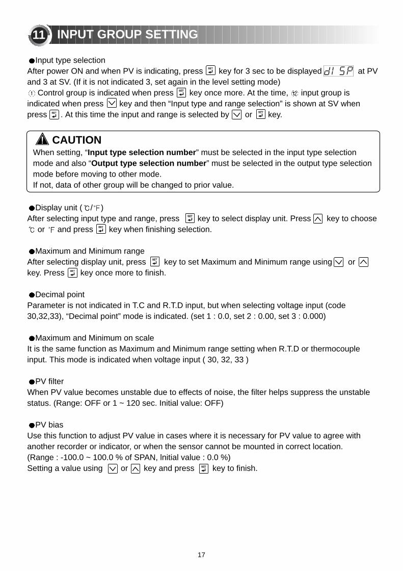
Input type selectionAfter power ON and when PV is indicating, press key for 3 sec to be displayed at PVand 3 at SV. (If it is not indicated 3, set again in the level setting mode)
Control group is indicated when press key once more. At the time, input group isindicated when press key and then “Input type and range selection” is shown at SV whenpress . At this time the input and range is selected by or key.
Display unit ( / )After selecting input type and range, press key to select display unit. Press key to choose
or and press key when finishing selection.
Maximum and Minimum rangeAfter selecting display unit, press key to set Maximum and Minimum range using or key. Press key once more to finish.
Decimal pointParameter is not indicated in T.C and R.T.D input, but when selecting voltage input (code30,32,33), “Decimal point” mode is indicated. (set 1 : 0.0, set 2 : 0.00, set 3 : 0.000)
Maximum and Minimum on scaleIt is the same function as Maximum and Minimum range setting when R.T.D or thermocoupleinput. This mode is indicated when voltage input ( 30, 32, 33 )
PV filterWhen PV value becomes unstable due to effects of noise, the filter helps suppress the unstablestatus. (Range: OFF or 1 ~ 120 sec. Initial value: OFF)
PV biasUse this function to adjust PV value in cases where it is necessary for PV value to agree withanother recorder or indicator, or when the sensor cannot be mounted in correct location.(Range : -100.0 ~ 100.0 % of SPAN, lnitial value : 0.0 %) Setting a value using or key and press key to finish.
INPUT GROUP SETTING
When setting, “Input type selection number” must be selected in the input type selectionmode and also “Output type selection number” must be selected in the output type selectionmode before moving to other mode. If not, data of other group will be changed to prior value.
11
CAUTION
18
K K J E T R B S L NU W
PlatinelJPt100 Pt100 1.000 ~ 5.000 V-10.00 ~ 20.00 mV0.0 ~ 100.0 mV
1.000 ~ 5.000 V-10.00 ~ 20.00 mV
0.0 ~ 100.0 mV
0.10% of F.S1digit
0.15% of F.S1digit
0.10% of F.S 1digit0.20% of F.S 1digit
0.10% of F.S1digit
0.10% of F.S1digit
0.10% of F.S1digit
-300~25000~2300
-300~2300-300~1800-300~75032~310032~330032~3100
-300~1300-300~2400-300~75032~420032~2500
-199.9~999.9-300~1180
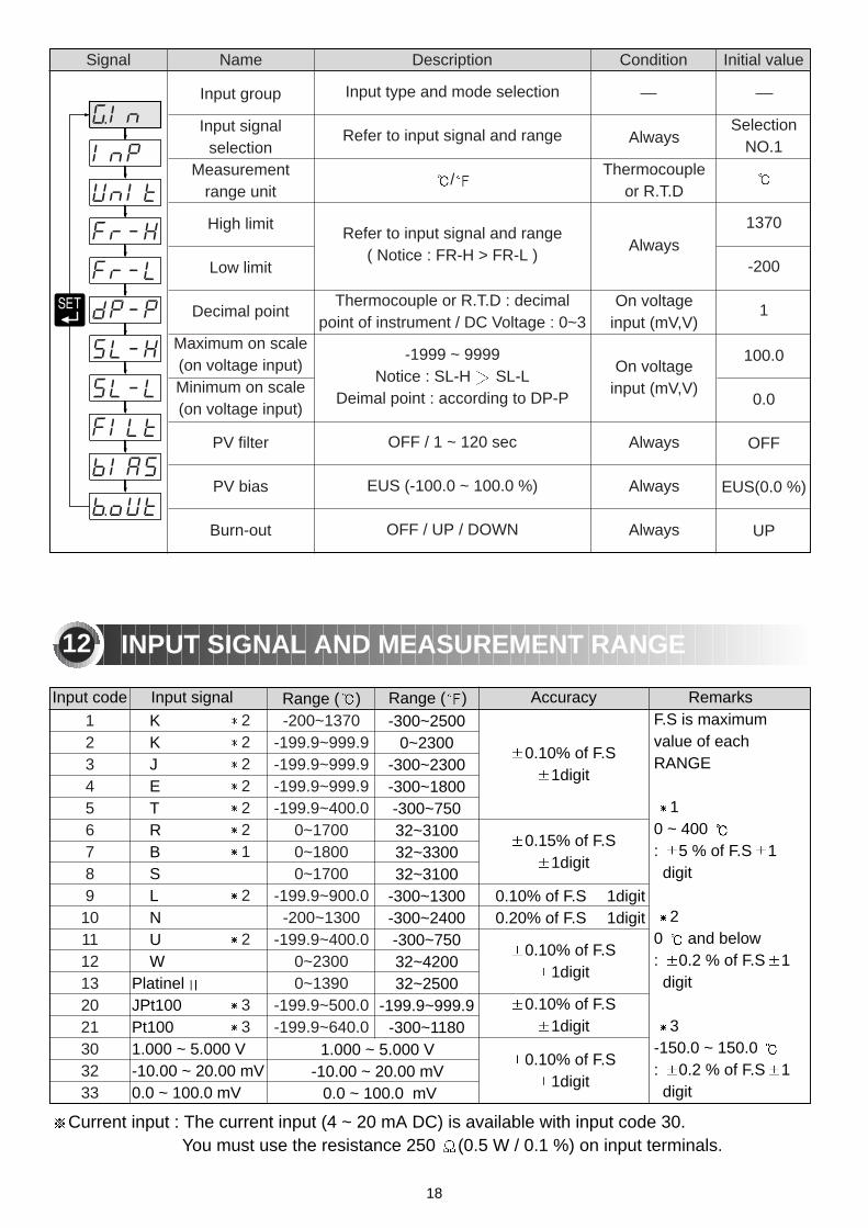
F.S is maximumvalue of eachRANGE
10 ~ 400 : 5 % of F.S 1digit
20 and below : 0.2 % of F.S 1digit
3-150.0 ~ 150.0 : 0.2 % of F.S 1digit
RemarksAccuracyRange ( )Range ( )Input signalInput code
123456789
101112132021303233
SelectionNO.1
1370
-200
1
100.0
0.0
OFF
EUS(0.0 %)
UP
Initial valueConditionDescriptionNameSignal
Input group
Input signalselection
Measurementrange unit
High limit
Low limit
Decimal point
Maximum on scale(on voltage input)Minimum on scale(on voltage input)
PV filter
PV bias
Burn-out
Input type and mode selection
Refer to input signal and range
/
Refer to input signal and range ( Notice : FR-H > FR-L )
Thermocouple or R.T.D : decimalpoint of instrument / DC Voltage : 0~3
-1999 ~ 9999 Notice : SL-H SL-L
Deimal point : according to DP-P
OFF / 1 ~ 120 sec
EUS (-100.0 ~ 100.0 %)
OFF / UP / DOWN
Always
Thermocouple or R.T.D
Always
On voltage input (mV,V)
On voltage input (mV,V)
Always
Always
Always
2222221
2
2
33
-200~1370-199.9~999.9-199.9~999.9-199.9~999.9-199.9~400.0
0~17000~18000~1700
-199.9~900.0-200~1300
-199.9~400.00~23000~1390
-199.9~500.0-199.9~640.0
12 INPUT SIGNAL AND MEASUREMENT RANGE
Current input : The current input (4 ~ 20 mA DC) is available with input code 30.You must use the resistance 250 (0.5 W / 0.1 %) on input terminals.
19
Output group
Output signal
Output operation
Cycle time
Cycle time of cooling output
Hysteresis of univesal type
Hysterecis of Heating /Cooling type
Output volume when inputdisconnection Output 1(Out1)
Output volume when inputdisconnection Output 2(Out2)
Maximum value
Minimum value
Output code(O T)
0123
OUT2OUT1
Always
Output code 1 ~ 3
Relay / SSR
Output code 4 ~ 12
ON/OFFControl Heating/ Cooling
Always
Heating /Cooling
PID Control
PID Control
(3 / 12)
REV
30 sec
30 sec
EUS(0.5 %)
0.5 %
0.0 %
0.0 %
100.0 %
0.0 %100.0%
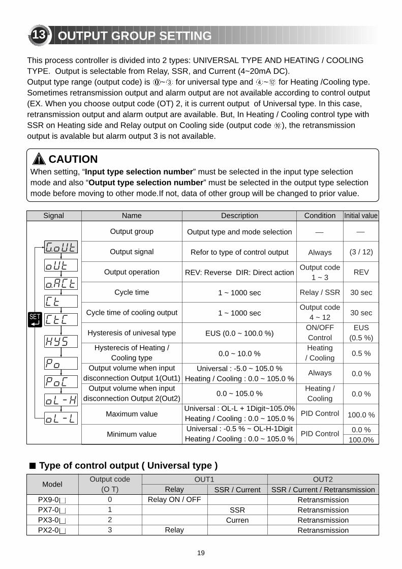
OUTPUT GROUP SETTING
Initial valueConditionDescriptionNameSignal
Output type and mode selection
Refor to type of control output
REV: Reverse DIR: Direct action
1 ~ 1000 sec
1 ~ 1000 sec
EUS (0.0 ~ 100.0 %)
0.0 ~ 10.0 %
Universal : -5.0 ~ 105.0 %Heating / Cooling : 0.0 ~ 105.0 %
0.0 ~ 105.0 %
Universal : OL-L + 1Digit~105.0%Heating / Cooling : 0.0 ~ 105.0 %Universal : -0.5 % ~ OL-H-1DigitHeating / Cooling : 0.0 ~ 105.0 %
RelayRelay ON / OFF
Relay
PX9-0PX7-0PX3-0PX2-0
SSR / Current
SSR Curren
Type of control output ( Universal type )
This process controller is divided into 2 types: UNIVERSAL TYPE AND HEATING / COOLINGTYPE. Output is selectable from Relay, SSR, and Current (4~20mA DC).Output type range (output code) is ~ for universal type and ~ for Heating /Cooling type.Sometimes retransmission output and alarm output are not available according to control output (EX. When you choose output code (OT) 2, it is current output of Universal type. In this case,retransmission output and alarm output are available. But, In Heating / Cooling control type withSSR on Heating side and Relay output on Cooling side (output code ), the retransmissionoutput is avalable but alarm output 3 is not available.
ModelSSR / Current / Retransmission
RetransmissionRetransmissionRetransmissionRetransmission
13
When setting, “Input type selection number” must be selected in the input type selectionmode and also “Output type selection number” must be selected in the output type selectionmode before moving to other mode.If not, data of other group will be changed to prior value.
CAUTION

20
Set value group is indicated with selecting Local mode or Remote mode in GROUP CONTROL(Not Program mode). “Select number of SV” is after setting 3 type of set value in Local mode,select each set value from external contact input to operate. After selecting number of set value,press key, you could set set-value of SV1, SV2, and SV3.
1
EU(0.0 %)
EU(0.0 %)
EU(0.0 %)
Relay(AL3)Relay(AL3)Relay(AL3)
SSRCurrent
RetransmissionSSR
CurrentRetransmission
SSRCurrent
Relay
Relay
Relay
SSRSSRSSR
CurrentCurrentCurrent
RetransmissionRetransmissionRetransmission
Model
456789
101112
Cooling (OUT2)Heating (OUT1)Output code(O T) SSR / CurrentRelay SSR / Current / Retransmission Relay
Initial valueConditionDescriptionNameSignal
Set value group
Select number of set value
Set SV 1
Set SV 2
Set SV 3
Set value setting
1 ~ 3
EU(0.0 ~ 100.0 %)
EU(0.0 ~ 100.0 %)
EU(0.0 ~ 100.0 %)
REM / LOCA
REM / LOCA
REM / LOCA
REM / LOCA
PX9-0PX7-0PX3-0PX2-0
SET VALUE GROUP SETTING14
EU : Value at an engineering unit in compliance with the range of an instrument.
21
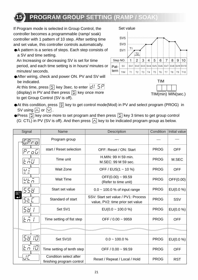
Initial valueConditionDescriptionNameSignal
PROGRAM GROUP SETTING (RAMP / SOAK)
OFF: Reset / ON: Start
H.MIN: 99 H 59 min.M.SEC: 99 M 59 sec.
OFF / EUS(1 ~ 10 %)
OFF(0.00) ~ 99.59 (Refer to time unit)
0.0 ~ 100.0 % of input range
SSV: Start set value / PV1: Processvalue, PV2: time prior set value
EU(0.0 ~ 100.0 %)
OFF / 0.00 ~ 9959
0.0 ~ 100.0 %
OFF / 0.00 ~ 99.59
Reset / Repeat / Local / Hold
OFF
M.SEC
OFF
OFF(0.00)
EU(0.0 %)
SSV
EU(0.0 %)
OFF
EU(0.0 %)
OFF
RST
PROG
PROG
PROG
PROG
PROG
PROG
PROG
PROG
PROG
PROG
PROG
Program group
start / Reset selection
Time unit
Wait Zone
Wait Time
Start set value
Standard of start
Set SV1
Time setting of fist step
Set SV10
Time setting of tenth step
Condition select afterfinishing program control
If Program mode is selected in Group Control, thecontroller becomes a programmable (ramp/ soak)controller with 1 pattern of 10 step. After setting timeand set value, this controller controls automatically.
A pattern is a series of steps. Each step consists ofa SV and time setting. An Increasing or decreasing SV is set for timeperiod, and each time setting is in hours/ minutes orminutes/ seconds.After wiring, check and power ON. PV and SV willbe indicated.At this time, press key 3sec. to enter(display) in PV and then press key once moreto get Group Control (SV is off).
At this condition, press key to get control mode(Mod) in PV and select program (PROG) inSV using or .Press key once more to set program and then press key 3 times to get group control (G: CTL) in PV (SV is off). And then press key to be indicated program group as below.
TIM
Set value
TIM(min) MIN(sec.)
15
Step NO.
Pat-tern

22
STD
OFF
Initial valueConditionDescriptionNameSignal
AUTO TUNING
Auto tuning group
Auto tuning type
Auto tuning start
Indicates Auto tuning
STD / LOW
OFF / 1~3 / AUTO
ABS
ABS
This controller has two types of auto-tuning as STD (Standard type) and LOW(Low PV type). Low PV type is the value 10% lower than the set value. Use this type where overshoot is to besuppressed.
Auto-tuning: The Auto-tuning function automatically measures, computes and set the optimumP.I.D and ARW contants. The Auto-tuning function can be activated at any timeduring the process after power ON; while temperature is rising or when control hasstabilized.Auto tuning is not operated when selecting “OFF” in selection mode of auto tuningstart.
16

23
Signal Name Description Condition Initial value
P.I.D group
Anti Reset Wind-Up
P.I.D group selection
n. Proportional band(P)
n. Integal time (I)
n. Derivative time (D)
n. Manual reset
n. Proportional band ofcooling side (P)
n. Integral time ofcooling side (I)
n. Derivative time ofcooling side (D)
n. Hysteresis
n. Zone point
Set P.I.D mode
Auto / 50.0 ~ 200.0 %
0 / 1 ~ 3
0.1 (H/C TYPE:0.0) ~ 999.9 %
OFF / 1 ~ 600 sec.
OFF / 1 ~ 6000 sec.
-5.0 ~ 105.0 %
0.0 (ON/OFF control) / 0.1 ~ 999.9
OFF / 1 ~ 6000 sec.
OFF / 1 ~ 6000 sec.
-100.0 ~ 50.0 %
EU (0) < 1.RP < 2.RP < EU(100.0 %)
P.I.D control
Always
P.I.D group
Always
Always
Integral time: OFF
Heating Cooling type
Heating Cooling type
Heating Cooling type
Heating Cooling type
ZONE = ON
Auto
0
5.0 %
240 sec.
60 sec.
50.0%
5.0 %
240 sec.
60 sec.
3.0 %
EU(100.0 %)
Time
Zone 3
Set point of Zone 2 (2,RP)
Set point of Zone 1 (1,RP)
Maximum Range (Eu:100 %)
Minimum (Eu: 0 %)
Zone 2
Zone 1
When checking P.I.D. values or setting SV in manual mode, this can be done in P.I.D. Group.Press key to get Anti Reset Wind value by auto or manual and then press once more to beindicated P.I.D mode which is selectable 3 types of P.I.D group (0~3). Example, “0” is no P.I.Dmode and after Auto tuning “1” using or and pressing , it is available to change P.I.Dvalue in zone “1” (“2” and “3” are same as “1”) When integral time is 0, manual reset mode is indicated and then you could set reset value toremove off set (range: -5 % ~ 105.0 % of proportional band). You could set 3 zones by selectingzone mode ON.
In diagram, “n” is available to set 1 ~ 3 and proportional band of cooling side, integral time of cooling side, hysteresis are indicated in Heating / Cooling type.
P.I.D GROUP17
24
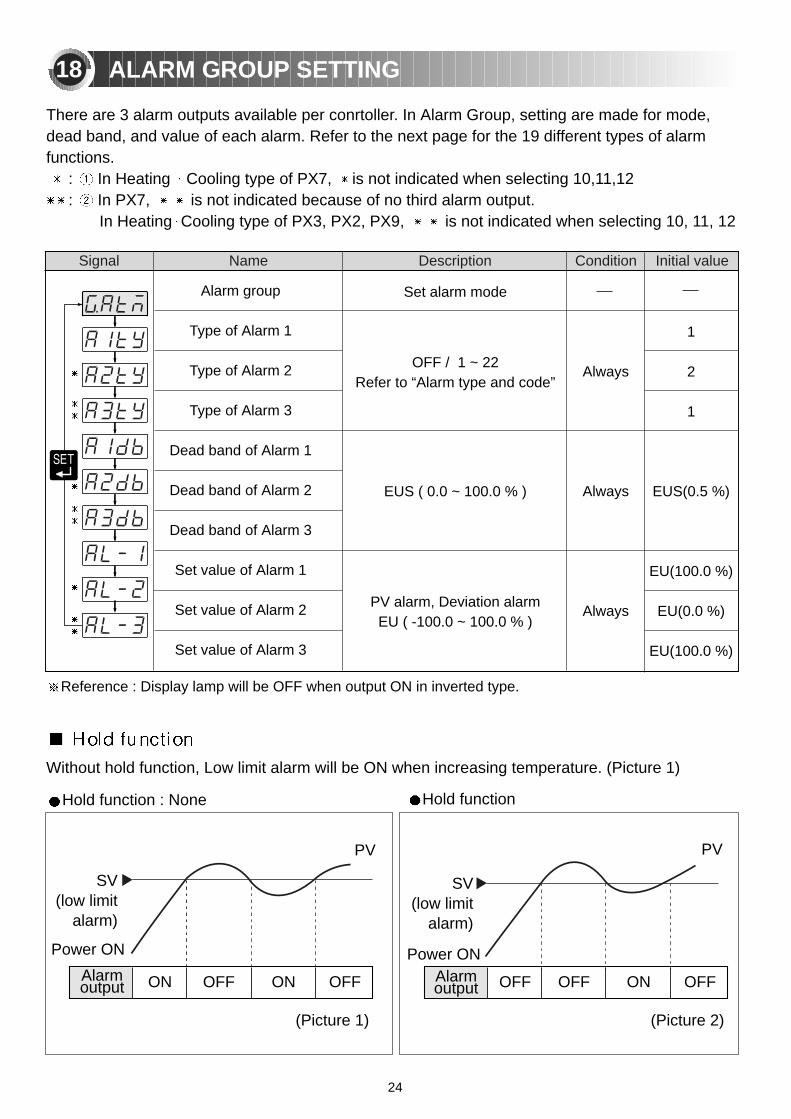
Name Description Condition Initial valueSignal
ALARM GROUP SETTING
1
2
1
EUS(0.5 %)
EU(100.0 %)
EU(0.0 %)
EU(100.0 %)
Always
Always
Always
Set alarm mode
OFF / 1 ~ 22 Refer to “Alarm type and code”
EUS ( 0.0 ~ 100.0 % )
PV alarm, Deviation alarmEU ( -100.0 ~ 100.0 % )
Alarm group
Type of Alarm 1
Type of Alarm 2
Type of Alarm 3
Dead band of Alarm 1
Dead band of Alarm 2
Dead band of Alarm 3
Set value of Alarm 1
Set value of Alarm 2
Set value of Alarm 3
There are 3 alarm outputs available per conrtoller. In Alarm Group, setting are made for mode,dead band, and value of each alarm. Refer to the next page for the 19 different types of alarmfunctions.
: In Heating Cooling type of PX7, is not indicated when selecting 10,11,12: In PX7, is not indicated because of no third alarm output.
In Heating Cooling type of PX3, PX2, PX9, is not indicated when selecting 10, 11, 12
18
Reference : Display lamp will be OFF when output ON in inverted type.
Without hold function, Low limit alarm will be ON when increasing temperature. (Picture 1)
SV(low limit
alarm)
Power ON
Alarm output ON OFF ON OFF
PV
(Picture 1)
SV(low limit
alarm)
Power ON
OFF OFF ON OFF
PV
(Picture 2)
Hold function : None Hold function
Alarm output
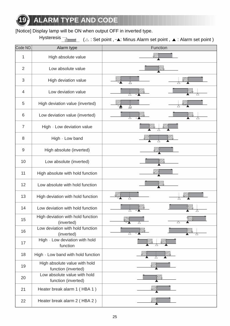
( : Set point , : Minus Alarm set point , : Alarm set point )
Code NO.
1
2
3
4
5
6
7
8
9
10
11
12
13
14
15
16
17
18
19
20
21
22
High absolute value
Low absolute value
High deviation value
Low deviation value
High deviation value (inverted)
Low deviation value (inverted)
High Low deviation value
High Low band
High absolute (inverted)
Low absolute (inverted)
High absolute with hold function
Low absolute with hold function
High deviation with hold function
Low deviation with hold function
High deviation with hold function(inverted)
Low deviation with hold function(inverted)
High Low deviation with holdfunction
High Low band with hold function
High absolute value with holdfunction (inverted)
Low absolute value with holdfunction (inverted)
Heater break alarm 1 ( HBA 1 )
Heater break alarm 2 ( HBA 2 )
Function
ALARM TYPE AND CODE
Alarm type
19
Hysteresis[Notice] Display lamp will be ON when output OFF in inverted type.
25
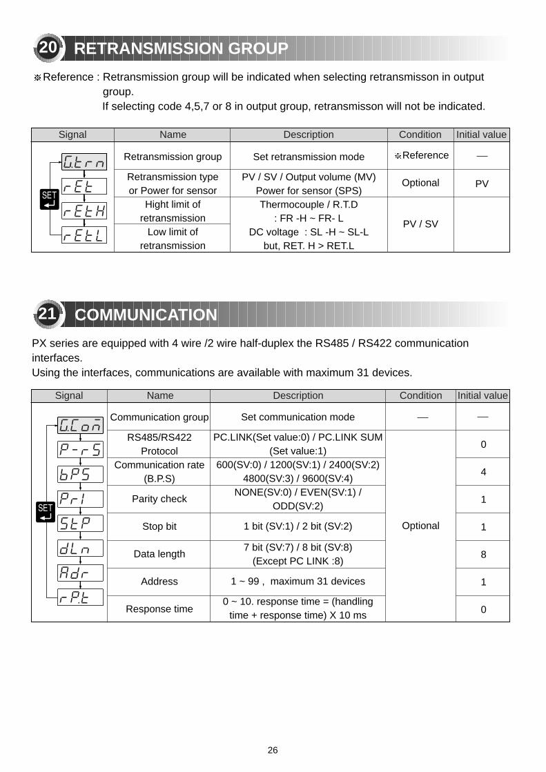
Set retransmission mode
PV / SV / Output volume (MV)Power for sensor (SPS)Thermocouple / R.T.D
: FR -H ~ FR- LDC voltage : SL -H ~ SL-L
but, RET. H > RET.L
Retransmission group
Retransmission typeor Power for sensor
Hight limit ofretransmission
Low limit ofretransmission
Signal Name Description Condition Initial value
Signal Name Description Condition Initial value
RETRANSMISSION GROUP
Reference
Optional
PV / SV
Reference : Retransmission group will be indicated when selecting retransmisson in outputgroup. If selecting code 4,5,7 or 8 in output group, retransmisson will not be indicated.
PV
COMMUNICATION
Communication group
RS485/RS422 Protocol
Communication rate(B.P.S)
Parity check
Stop bit
Data length
Address
Response time
Set communication mode
PC.LINK(Set value:0) / PC.LINK SUM(Set value:1)
600(SV:0) / 1200(SV:1) / 2400(SV:2) 4800(SV:3) / 9600(SV:4)
NONE(SV:0) / EVEN(SV:1) /ODD(SV:2)
1 bit (SV:1) / 2 bit (SV:2)
7 bit (SV:7) / 8 bit (SV:8) (Except PC LINK :8)
1 ~ 99 , maximum 31 devices
0 ~ 10. response time = (handlingtime + response time) X 10 ms
Optional
0
4
1
1
8
1
0
PX series are equipped with 4 wire /2 wire half-duplex the RS485 / RS422 communicationinterfaces.Using the interfaces, communications are available with maximum 31 devices.
20
21
26
Remote group
High limit voltage of remote input
Low limit voltage of remote input
High limit on scale
Low limit on scale
PV Filter
PV Bias
Signal Name Description Condition Initial value
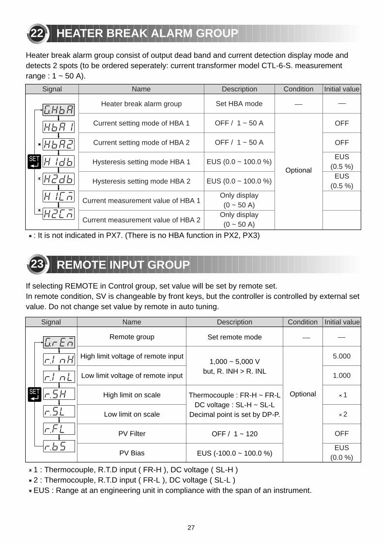
Heater break alarm group
Current setting mode of HBA 1
Current setting mode of HBA 2
Hysteresis setting mode HBA 1
Hysteresis setting mode HBA 2
Current measurement value of HBA 1
Current measurement value of HBA 2
Set HBA mode
OFF / 1 ~ 50 A
OFF / 1 ~ 50 A
EUS (0.0 ~ 100.0 %)
EUS (0.0 ~ 100.0 %)
Only display(0 ~ 50 A)
Only display(0 ~ 50 A)
OFF
OFF
EUS(0.5 %)
EUS(0.5 %)
5.000
1.000
1
2
OFF
EUS(0.0 %)
Signal Name Description Condition Initial value
REMOTE INPUT GROUP
If selecting REMOTE in Control group, set value will be set by remote set.In remote condition, SV is changeable by front keys, but the controller is controlled by external setvalue. Do not change set value by remote in auto tuning.
Set remote mode
1,000 ~ 5,000 Vbut, R. INH > R. INL
Thermocouple : FR-H ~ FR-L DC voltage : SL-H ~ SL-L
Decimal point is set by DP-P.
OFF / 1 ~ 120
EUS (-100.0 ~ 100.0 %)
HEATER BREAK ALARM GROUP
Heater break alarm group consist of output dead band and current detection display mode anddetects 2 spots (to be ordered seperately: current transformer model CTL-6-S. measurementrange : 1 ~ 50 A).
22
23
1 : Thermocouple, R.T.D input ( FR-H ), DC voltage ( SL-H )2 : Thermocouple, R.T.D input ( FR-L ), DC voltage ( SL-L )EUS : Range at an engineering unit in compliance with the span of an instrument.
: It is not indicated in PX7. (There is no HBA function in PX2, PX3)
Optional
Optional
27

MA02
01E0
5011
7


