2017 ASEE Zone II Conference
© American Society for Engineering Education, 2017
Low-Cost Groundwater Development: Manual Drilling in
Academic Research and Training
Mónica C. Resto1,2, Michael F. MacCarthy2,1, and Kenneth E. Trout1 1University of South Florida; 2Mercer University
Abstract
Manual drilling techniques can be of value in academic research and training environments, and
are increasingly being promoted as a cost-effective way of providing water for drinking and
irrigation purposes in developing communities throughout the world. The relatively low cost of
manually drilled wells, compared to machine-drilled or hand-dug wells, as well as the relative
portability of their equipment, make them an attractive water supply option when hydrogeological
conditions are favorable. Those same qualities also make manually drilled wells useful in many
academic research and training situations. The research consists of an assessment of percussion-
jetting-rotation manual drilling, a low-cost hybrid method developed in Bolivia. The equipment
set-up is assessed for relevance in academic field research, where collection of hydrogeological
data is often limited by the expense of conventional machine drilling. The study also considers
how manual drilling can be used to teach essential aspects of drilling concepts and groundwater
science from a field perspective. Nine monitoring wells were installed at the University of South
Florida Geological Park (USF GeoPark) using the manual percussion-jetting-rotation drilling
method, up to a maximum depth of nine meters, through sands, clays, and thin layers of limestone.
Drilling, well installation, and well development experiences were recorded. Geology was
observed and logged during drilling. For training purposes, groundwater flow was determined
between three wells. Hydraulic head was measured in each well, and hydraulic conductivity was
measured in one well.
Keywords
EMAS, well, water supply, appropriate technology
I. Introduction
The presented work is part of research conducted by the low-cost groundwater development
applied research group at the University of South Florida and Mercer University. This project
includes properly developing nine wells drilled in the USF Geological Park (USF GeoPark), an
open area on the University of South Florida campus in Tampa, Florida, from 2013-2015.
Additionally, installed wells were monitored bimonthly to establish groundwater flow data. A goal
for this project was to determine if the drilling fluid could be adequately removed during the well
development process so as to not interfere with the monitoring of the wells. Following this work,
a second phase of the project will be implemented (in 2017) where a low-cost multi-level
monitoring system will be installed in a manually drilled well at the USF GeoPark.
EMAS Manual Well Drilling Method The EMAS (Escuela Movil Aguas y Saneamiento Basico) manual well drilling method was
developed by Wolfgang Buchner, with an aim of helping to provide potable water at affordable
costs for families in developing countries1. This method incorporates percussion, jetting, and
rotation techniques. The materials required for installing wells using EMAS drilling are low-cost

2017 ASEE Zone II Conference
© American Society for Engineering Education, 2017
and generally widely available in developing countries. This is advantageous because it allows for
the cost per meter of installed well to be sufficiently affordable to sustain a family’s, or several
families’, water needs. This drilling method could be used in varied locales and soil strata,
depending on the type of drill bit used during drilling2. ‘EMAS standard’, as it is called, is capable
of drilling up to 100-meter deep wells3. The limiting factor to the depth of drilling is often human
power; the deeper the borehole gets, the more pipe is needed, and the heavier the drilling assembly
becomes. Presence of consolidated bedrock may also cease drilling.
Figure 1 shows the details of the EMAS standard drilling method, which consists of three
techniques. The percussion technique is performed by raising and dropping the drilling assembly
(comprised of the drill pipes, couplings, and drill bit) using a rope and pulley system. Rotation
refers to turning the drilling assembly via the drill handle a quarter to half turn in each direction,
upon drill bit impact at the bottom of the hole. Jetting makes use of a trench-pit system, mud pump,
mud hose, and the drilling assembly. Drilling fluid (composed of water and bentonite mixed in the
mud pit) is pumped via the mud pump, through the hose, and down the drill pipes. The drilling
fluid exits through open spaces in the drill bit and scours the soil. As pumping continues, the
drilling fluid carries drilled cuttings out of the borehole and into the settling pit. There the cuttings
settle out, and the drilling fluid enters the mud pit to be recirculated.
Figure 1. Diagram of the EMAS standard drilling method1.
Manual Drilling and Well Installation During the summer of 2013, five wells were installed at the USF GeoPark, by a team of
undergraduate students, during the Research Experience for Undergraduates Tampa
Interdisciplinary Environmental Research (REU-TIER) program. The purpose of the research
conducted during the REU-TIER program was to introduce EMAS standard drilling and to assess
its academic applicability. Achievements during this ten-week program included:

2017 ASEE Zone II Conference
© American Society for Engineering Education, 2017
• Learning about and understanding the EMAS standard drilling method
• Adapting the drilling techniques to better suit them for research applications
• Repairing and improving EMAS standard drilling equipment (previously built by USF
graduate students and engineering technicians)
• Learning proper site assessment for deciding well locations
These wells were installed as cluster wells. This practice is helpful when the goal is to monitor
various soil layers for groundwater flow or contaminant concentrations. This is achieved by
installing a main well in the deepest possible groundwater unit, and then installing satellite wells
in water saturated lithological layers shallower than the main well4.
An installed well is comprised of the well pipe (usually PVC) with a well screen at the end. This
screen is either manufactured to a certain size, or can be cut manually with a hand saw, and allows
for the flow of water into the well. In monitoring wells, carefully choosing the well screen length
allows for isolation of one soil layer for study purposes. The well screen is usually covered by a
gravel pack, comprised of sand and poured into the borehole. This keeps fine sediment out of the
well water, which may impact water quality testing results and impair water for consumption.
Four additional wells were installed during the year following the Summer 2013 REU-TIER.
Well Development & Well Monitoring Well development is the removal of the drilling fluid, which can clog the gravel pack and well
screen, in order to make the well as productive as possible and not interfere with the groundwater
flow. Ineffective removal of the bentonite-containing fluid can decrease the productivity of the
well and cloud the collected water. It can also interrupt the groundwater flow and make well
monitoring difficult. This investigation involved determining if the bentonite could be sufficiently
removed from the well screen and gravel pack.
The second goal for this research was to monitor all of the installed wells. The purpose of this
component was to successfully carry out well monitoring techniques, gather data regarding the
productivity of the aquifer at each well, and determine the general groundwater flow direction at
the USF GeoPark. This component was important and demonstrated that these specific well-
monitoring tests could be done on EMAS standard drilled wells. The monitoring program also
supported the summer REU-TIER conclusion that an EMAS drilled well can assist academic
researchers to conduct their research without major financial investment (e.g. in buying or renting
costly drilling rigs).
II. Background Well Development Well development is thought as most important in regions where groundwater is scarce because it
significantly improves well productivity by guaranteeing that the flow into the well is unobstructed
by sand and drilling fluid, thereby maximizing well capacity.
Methods for developing wells can vary and are dependent on in-situ lithological conditions. These
methods are utilized to achieve several objectives. One objective of well development is to repair
the damage to the aquifer and soil surfaces within the borehole due to the drilling process. Drilling
fluid damages soil surfaces by leaving ‘mud cake’ on the walls of the borehole and bedrock which

2017 ASEE Zone II Conference
© American Society for Engineering Education, 2017
must be dislodged and flushed out. The obstruction caused by these foreign particles causes the
groundwater flowing toward the well to become crowded. Well development also improves flow
through and stability of the adjacent aquifer5. This is especially necessary for production wells,
where well capacity must be maximized, and important for monitoring wells. Wells become more
productive when sediment is removed because there is more porous space for water to flow
through. Additionally, flushing out fines from the area adjacent to the pipe will prevent future
contamination of the well water.
Bentonite drilling fluid is problematic because it is pervasive and forms a thick “mud cake” on the
borehole wall. Alternatively, one may opt for a polymer-based drilling fluid. These can degrade
over time and also create a much thinner “mud cake”.
Well development requires planning and consideration of available equipment, time constraints,
and financial resources. Development methods and drilling fluid options may differ with respect
to well purpose, desired well capacity, aquifer characteristics, and installed well screen.
Well development methods include:
• Chemical: involves gently or violently acting solvents that dissolve clogging material and open
up pore spaces for water to pass more efficiently. These could pose human health hazard, so it is
imperative to assure that they are safe to use and approved by the local governing authority.
• Washing and Backwashing: washing (overpumping) involves removing water from the well
which causes sediment to flow from the well and leave the soil adjacent to the well sediment-free.
This method is not effective on its own because the water is only flowing in the direction of the
removal. The backwashing technique involves injection of water into the well. This method must
also be used in combination with others because it is not very effective if used alone.
• Mechanical Surging: involves using a plunger tool to repeatedly and quickly suck and push the
water through the well screen to dislodge particles and open porous space. This method could
potentially damage the aquifer. It is best to utilize a plunger with a one way valve to remove the
sediment rich water from the well.
Slug Tests and Hydraulic Conductivity The most reliable test for determining hydraulic conductivity is the aquifer test. This test cannot
be performed accurately for aquifers where “sustained flow rates” cannot be maintained, and
cannot be performed at all for pumping out groundwater that is possibly contaminated6. The flow-
meter and tracer tests are used to compare the results from other hydraulic conductivity tests and
can determine the velocity and flow path of groundwater in a site. These tests are unfortunately
both time consuming and expensive.
Slug tests involve measuring the rise or fall of the water level when water is instantaneously
removed or introduced, respectively. A disadvantage is that this test cannot be conducted for
aquifers characterized by a transmissivity greater than 7000 cubic feet per day or for slow aquifers.
Wells drilled and installed in a clay-rich condition can have low permeability and the slug test
would not be able to test these conditions. A well must be developed properly before using slug
tests to estimate hydraulic conductivity.

2017 ASEE Zone II Conference
© American Society for Engineering Education, 2017
III. Results and Discussion A review of literature on the study area gave an understanding of the different geological profiles
present at the USF GeoPark. In order to test the capabilities of the drilling method, five sites with
expected different strata were chosen (Figure 2).
Figure 2. Shows the extent of the study area and locations of each site.
Three wells were drilled at each of three sites (Site #1, Site #2, and Site #4). At each of these sites,
the main well was drilled and installed at maximum depth and data were gathered on the soil
profile for the site. Utilizing that soil profile, the other two wells were installed at different,
shallower geological layers below the water table.
Three drill bits were tested and are shown in Figure 3. The universal drill bit performed best in the
overburden at the GeoPark. It did not get clogged through clay, unlike the sand bit, and was tough
through unconsolidated limestone. Utilizing the universal drill bit minimized interruptions to the
drilling process.

2017 ASEE Zone II Conference
© American Society for Engineering Education, 2017
Figure 3. Drill bits utilized in this research (from top to bottom): Christmas tree, sand, and
universal.
Short-circuiting of the drilling fluid containing cuttings through the trench-pit system (shown in
Figure 4) was observed. To prevent this, two modifications were made to the system. First, the
trench entering the settling pit (labeled ‘A’) and the trench leaving the settling pit were dug
perpendicular to each other. Secondly, the entrance mouth to the settling pit was dug deeper than
the exiting mouth. This allowed for the drilled cuttings to be more effectively settled out, and the
drilling fluid to be skimmed off the top of the settling pit before passing into the trench to the mud
pit (at ‘B’).
Figure 4. Trench pit system, consisting of (A) the settling pit, (B) the mud pit, and connecting
trenches dug perpendicular to each other.

2017 ASEE Zone II Conference
© American Society for Engineering Education, 2017
Asynchronous pumping of the mud pump and lifting of the drill assembly was causing pressure to
build up within the drill assembly and mud hose (due to the drill bit being submerged in sediment)
and forcing the hose off of the drilling handle. To prevent this, synchronicity was established
between the jetting and percussion techniques: the drilling fluid was pumped during the upstroke
of the drilling assembly.
Data gathered from this research included soil removed at each site, observed from the drilled
cuttings exiting the annulus and from the ‘feel’ of the drilling. This data was compiled to create a
soil profile at each site, and was crucial in determining the depth of the installed satellite wells.
Figure 5 shows the soil profile for each well at Site #2.
Figure 5. The soil profile for the three wells at Site #2.
Conducting this research with minimal interruptions required more than three persons. A minimum
of three people are required during drilling: at least one person lifting the drilling ensemble, one
person rotating the handle (drill bit), and one person pumping the drilling fluid. An additional
person is advantageous for managing the viscosity of the drilling fluid, unclogging the mud pump
intake, and assisting with adding sections to the drilling assembly.
Preliminary trials for developing the wells to sufficiently remove the bentonite drilling fluid have
proven minimally successful. The time lapse between well installation and development (1.5
years) was not ideal. The chosen well development method (washing and backwashing) appeared
to clear the wells of sediment temporarily, but the water would again become murky after a period
of time. Well development also shed light on interactions between wells, evident by the fact that
continuously pumping one well would significantly decrease the hydraulic head within an adjacent
well. For development of future wells, it is planned to combine manual washing and backwashing
with manual surging.
2017 ASEE Zone II Conference
© American Society for Engineering Education, 2017
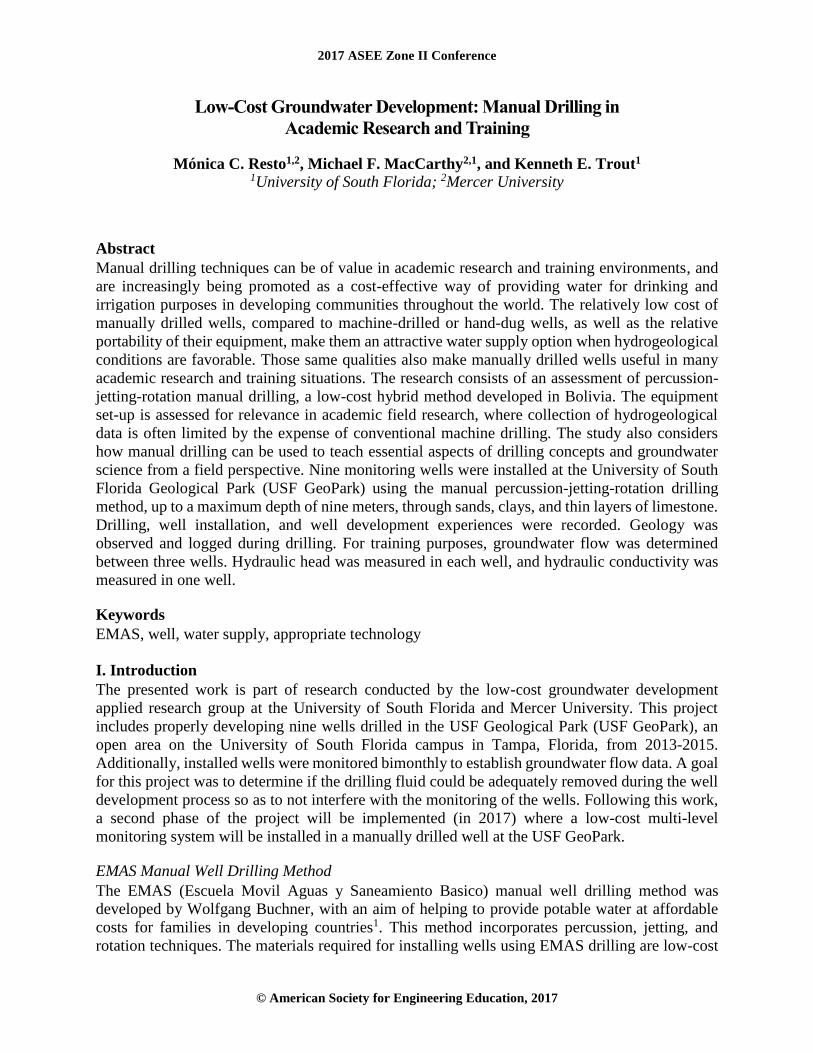
To demonstrate the possibility of using such monitoring wells for testing, slug tests were conducted
on one well. EPA Standard Operating Procedure #2046 was utilized and values for hydraulic
conductivity were calculated (for three trials). The values shown in Table 1 correlate well with
values given by Freeze and Cherry7 for silty and clean sand.
Table 1. Hydraulic conductivity (K) values calculated from three rising head tests on well #1.a.
Well #1a: K value
(meter/day)
4.63
5.10
4.58
In analyzing the REU-TIER program achievements and costs, it was concluded that university
researchers can gain valuable experience in learning the process of well installation using the
EMAS standard method. During drilling, students can gain experience in soil classification to
understand the soil profile and lithology of the study site. These drilled wells can become
monitoring wells to test for groundwater flow and hydraulic conductivity, groundwater
contaminants, and water quality. The EMAS standard method was deemed successful in providing
a low-cost way of drilling cluster wells for monitoring. This method can be used in university
teaching labs to give student researchers valuable hands-on experience that can be applied in
engineering design, construction, and monitoring work in domestic and international settings.
IV. Next Steps Well monitoring techniques have improved greatly in the past three decades; it is no longer
necessary to install well clusters to monitor groundwater. Multilevel monitoring systems have been
designed to monitor different layers of groundwater flow through different ports in the same well.
This is an advantage since well material is only needed for one well installation, and this method
can be advantageous in areas with limited space. In 2017, a low-cost multi-level monitoring system
will be installed on a new manually drilled well at the USF GeoPark. A cost analysis for this
method of well monitoring will be performed, and compared to the well cluster approach to
establish which is better suited for academic research.
Acknowledgments
The authors thank Julian Pawlikiewicz and Eric Bodine, who participated in the research as
members of the Summer 2013 REU-TIER manual well drilling research team. This material is
based upon work supported by the National Science Foundation under Grant No. 0851910.
2017 ASEE Zone II Conference
© American Society for Engineering Education, 2017
References
1 MacCarthy, M. F., Buckingham, J. W., and Mihelcic, J. R., “EMAS Household Water
Supply Technologies in Bolivia. Increasing Access to Low-Cost Water Supplies in Rural
Areas,” Field Note No. 2013-4, Rural Water Supply Network, 2013.
2 Rural Water Supply Network, “Implementation Handpump Technology [EMAS
Drilling],” Retrieved from http://www.rural-water-supply.net/en/implementation/manual-
drilling/emas-drilling.
3 Cloesen, P, “EMAS Drilling,” May 2007.
4 Harlan, R. L., Kolm, K. E., and Gutentag, E. D., “Water-well design and construction,”
Elsevier, 1989.
5 Well Drilling School, “Well Development,” Retrieved from
http://welldrillingschool.com/courses/pdf/WellDevelopment.pdf.
6 Campbell, M. D., Starrett, M. S., Fowler, J. D., and Klein, J. J., “Slug Test and Hydraulic
Conductivity,” November 1999.
7 Freeze, R. A., and Cherry, J. A., Groundwater, 1979.
Biographical Information
Mónica C. Resto
Mónica Resto is pursuing her Masters in Environmental Engineering at Mercer University. She
received her Bachelors of Science in Civil Engineering from the University of South Florida. Her
research interest is in groundwater flow, geology, appropriate technologies, and engineering for
development. Her graduate research involves utilizing low-cost, portable technologies to study
mountainous geology and hydrogeology and provide community water supplies in isolated
developing communities.
Michael F. MacCarthy
Dr. Mike MacCarthy is an Assistant Professor of Environmental Engineering at Mercer University.
He received his Ph.D. in Civil Engineering (Water Resources concentration) from the University
of South Florida. He is the Director of Mercer’s Engineering for Development program
(e4d.mercer.edu). His research interests include global WASH (water, sanitation, & hygiene), low-
cost water technologies, self-supply, and social marketing. He teaches undergraduate and graduate
courses in water resources engineering and engineering for development.
Kenneth E. Trout
Dr. Ken Trout is an Associate in Research in the Department of Civil and Environmental
Engineering at the University of South Florida. He received his Ph.D. in geology from the
University of South Florida. His primary research interest is in groundwater modeling and the
interaction of surface water and groundwater and in improving the prediction of uncertainty and
reliability of complex mathematical models. He teaches several undergraduate computer-based
engineering classes and a graduate geology course in groundwater modeling.


