D.I. D.I.
D.I. D.I.
D.I. D.I.
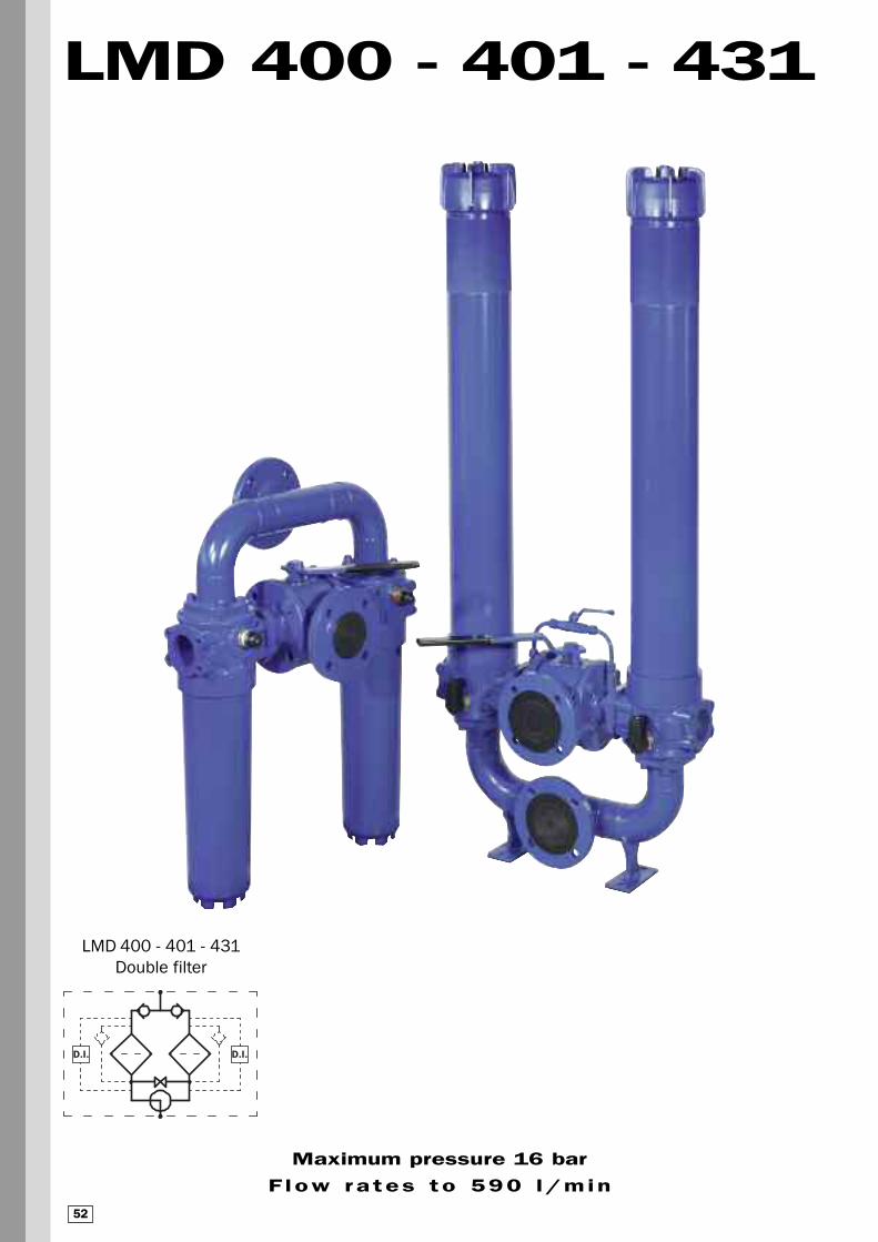
Maximum pressure 16 bar
F low ra tes to 590 l/min
LMD 400 - 401 - 431
LMD 400 - 401 - 431
Double filter
52

Filter housing (Materials)
• Head: Anodised Aluminium
• Housing: Anodised Aluminium
• Manifolds: Steel - Painted black
• Bypass valve: Steel
• 3-way ball valve: Steel housings - Stainless Steel ball
• Valve: Phosphated Steel - Stainless Steel
Pressure
• Working pressure: 16 bar (1.6 MPa)
• Test pressure: 25 bar (2.5 MPa)
Temperature
• From -25°C to +110°C
Bypass valve
• Opening pressure 3.5 bar ±10%
• Other opening pressures on request.
Filter elements Δp
• Series N and W elements: 20 bar
• Oil flow from exterior to interior.
Seals
• Standard FPM series V
Weights (kg)Length
• LMD400/401 4 60
• LMD400/401 5 65
• LMD400/401 6 72
• LMD431 5 68
• LMD431 6 75
Volumes (dm3)
Length
• LMD400/401/431 4 18
• LMD400/401/431 5 24
• LMD400/401/431 6 32
Connections
Inlet-Outlet
• Twin vertically mounted (excluded version LMD 400)
• In-Line
Compatibility (to ISO 2943)
• Housings compatible with:
Mineral oils - aqueous emulsions
synthetic fluids, water and glycol.
• The filter elements are compatible with:
Mineral oils, Synthetic fluids
Aqueous emulsions, water and glycol
(series W required).
• NBR seals series A, compatible with:
Mineral oils - aqueous emulsions
synthetic fluids, water and glycol.
• V series FPM seals, compatible with:
Synthetic fluids type HS-HFDR-HFDS-HFDU
Filter housing Δp pressure drop
The curves are plotted utilising mineral oil
with density of 0.86 kg/dm3 to ISO 3968.
Δp varies proportionally with density.
TTeecchhnniiccaall ddaattaa
6550 10200 15300
Filter Element AreaFilter element in stainless steel mesh
4 5 6
CU 400
Values expressed in cm2
Length
Type
9
Δp b
ar
6
3
0,000 140 280 420 560 700
LMD 400/401/431
0,3
0,4
0,5
0,6
0,2
0,1
Δp b
ar
0,00
Valves
Bypass valve pressure drop
For individual filter body
Flow rate l/min
Flow rate l/min
LMD 400/401/431 Δp Housing
100 200 300 400 500 600
53
2 1/2”
2,5 m/sec.
5 m/sec.
500
1000
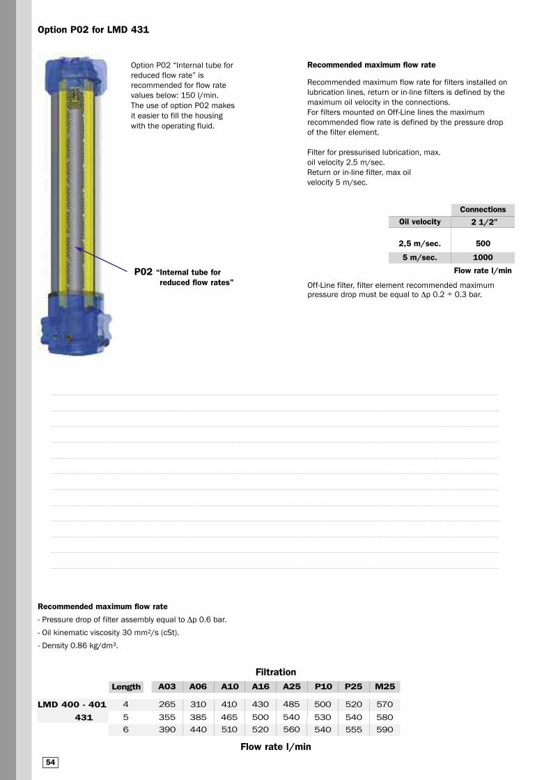
Option P02 for LMD 431
Flow rate l/min
Connections
Oil velocity
Recommended maximum flow rate
Recommended maximum flow rate for filters installed on
lubrication lines, return or in-line filters is defined by the
maximum oil velocity in the connections.
For filters mounted on Off-Line lines the maximum
recommended flow rate is defined by the pressure drop
of the filter element.
Filter for pressurised lubrication, max.
oil velocity 2.5 m/sec.
Return or in-line filter, max oil
velocity 5 m/sec.
Off-Line filter, filter element recommended maximum pressure drop must be equal to Δp 0.2 ÷ 0.3 bar.
Option P02 “Internal tube for
reduced flow rate” is
recommended for flow rate
values below: 150 l/min.
The use of option P02 makes
it easier to fill the housing
with the operating fluid.
P02 “Internal tube for reduced flow rates”
Filtration
Flow rate l/min
A03 A06 A10 A16 A25 P10 P25 M25
Recommended maximum flow rate
- Pressure drop of filter assembly equal to Δp 0.6 bar.
- Oil kinematic viscosity 30 mm2/s (cSt).
- Density 0.86 kg/dm3.
Length
390 440 510 520 540 555 5906 560
265
355
310
385
410
465
430
500
500
530
520
540
570
580
4
5
485
540
LMD 400 - 401
431
54
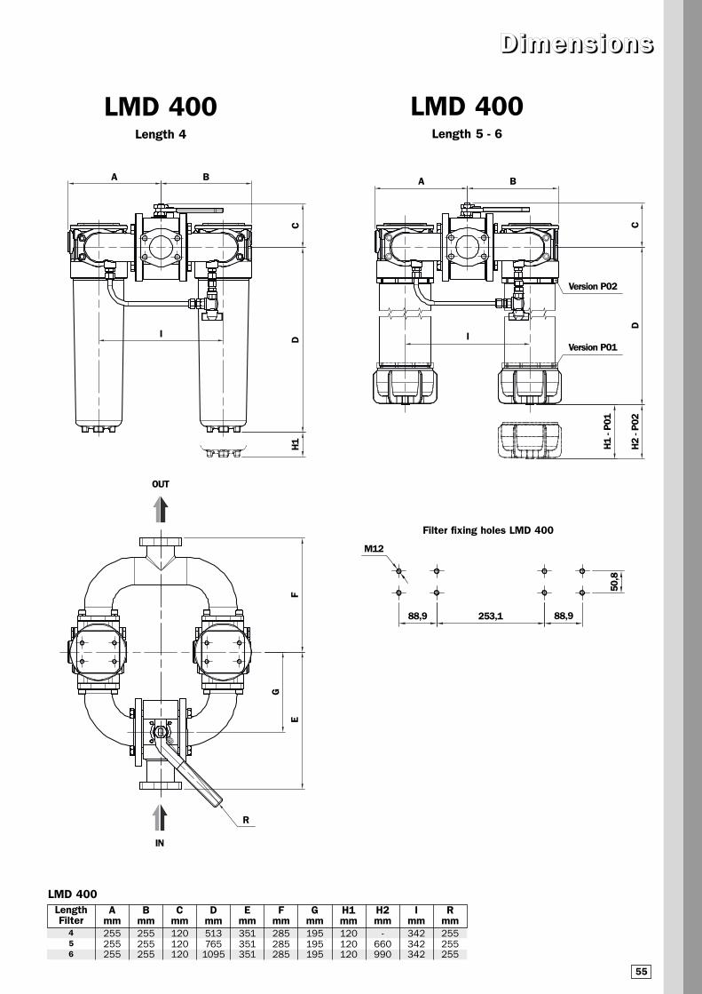
LMD 400Length 4
LMD 400Length 5 - 6
DDiimmeennss iioonnss
LMD 400LengthFilter
Amm
456
H2
- P02
H1
- P01
DC
A B
I
H1
DC
A B
I
253,150
,888,988,9
M12
R
FE
G
Version P01
Version P02
Filter fixing holes LMD 400
Bmm
Cmm
Dmm
Emm
Fmm
Gmm
H1mm
H2mm
Imm
Rmm255255255
255255255
255255255
120120120
513765
1095
351351351
285285285
195195195
120120120
342342342
-660990
IN
OUT
55

FVersionF1 - F2
GVersionF3 - F4
LMD 401Length 4
LMD 401Length 5 - 6
LMD 401LengthFilter
Amm
456
H2
- P02
H1
- P01
E
C
I
H1
DC
E
I
A
B
R
Version P01
Version P02
Bmm
Cmm
Dmm
Emm
Fmm
Gmm
H1mm
H2mm
Imm
Rmm
D
640640640
250250250
228228228
513765
1095
79610481378
156156156
156156156
120120120
-660990
470470470
255255255
56
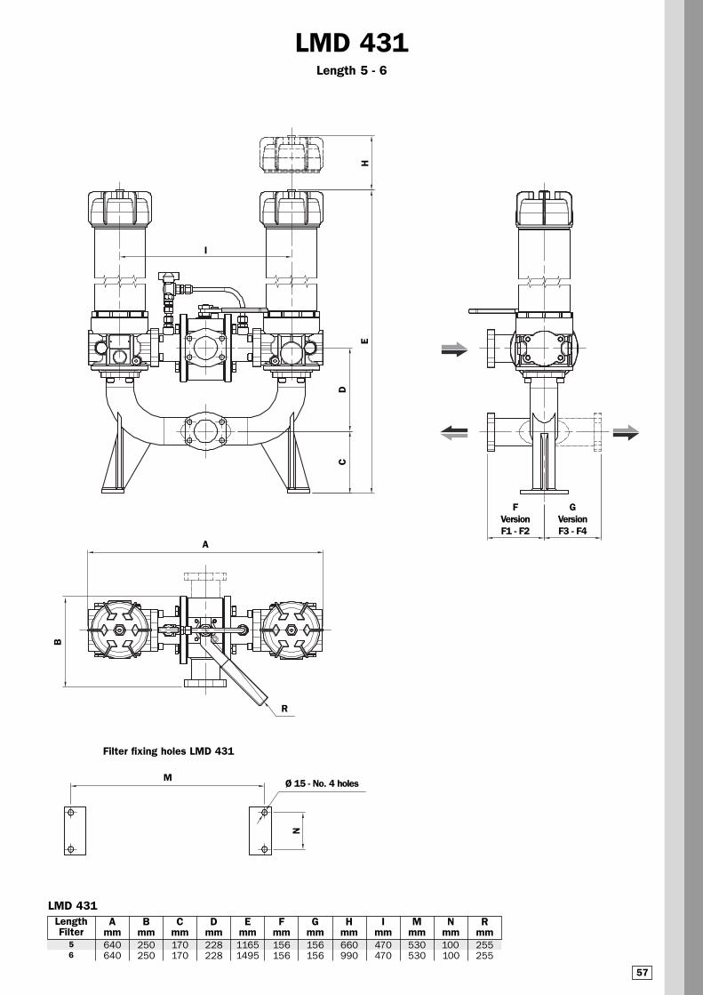
Ø 15 - No. 4 holes
Filter fixing holes LMD 431
FVersionF1 - F2
GVersionF3 - F4
LMD 431Length 5 - 6
C
H
I
D
E
A
B
R
M
N
LMD 431LengthFilter
Amm
56
Bmm
Cmm
Dmm
Emm
Fmm
Gmm
Hmm
Imm
Mmm
Nmm100100
640640
250250
170170
228228
11651495
156156
156156
660990
530530
470470
Rmm255255
57
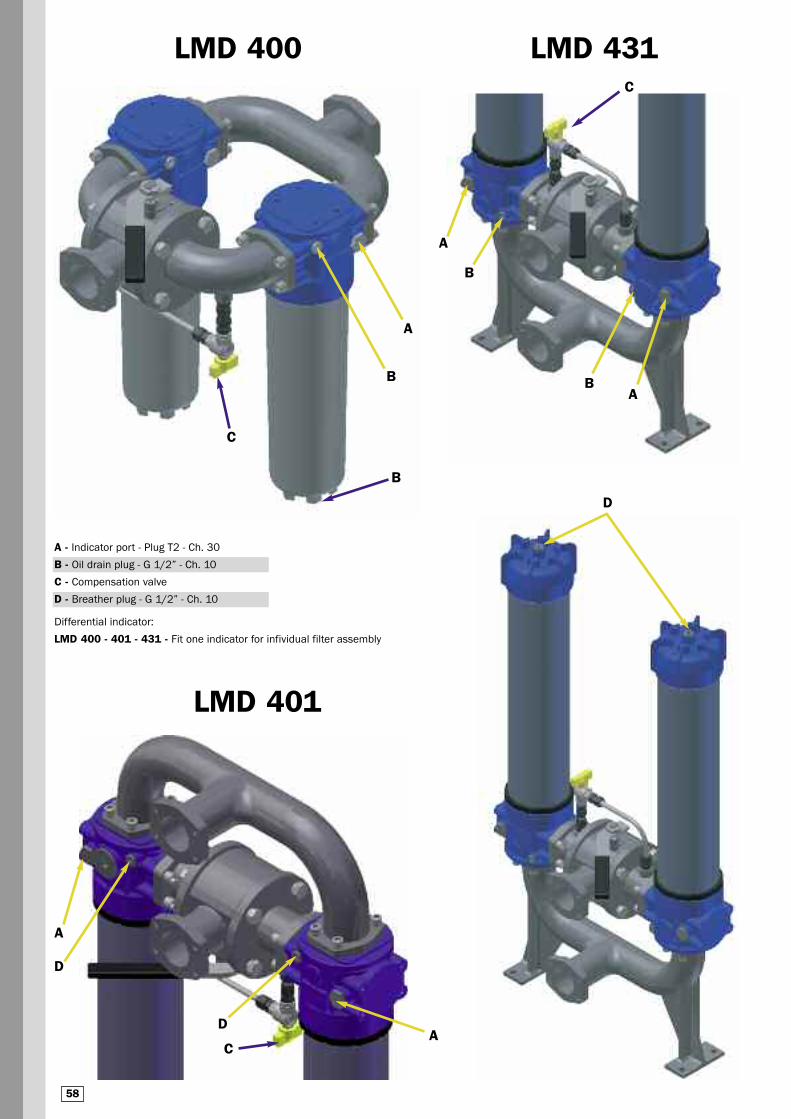
LMD 431LMD 400
D
A
B
C
C
A
B
BA
B
D
D
A
A
C
LMD 401
A - Indicator port - Plug T2 - Ch. 30
B - Oil drain plug - G 1/2” - Ch. 10
C - Compensation valve
D - Breather plug - G 1/2” - Ch. 10
Differential indicator:
LMD 400 - 401 - 431 - Fit one indicator for infividual filter assembly
58
3 4b
4b
1
5a
5b
4b3
7
5b5a
6
2
4a
5d
5c
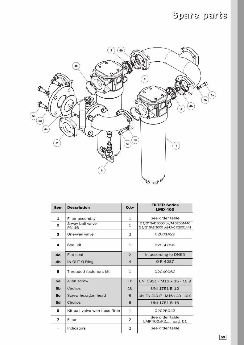
SSppaarree ppaarr ttss
Item
1
2
3
4
4a
4b
5
5a
5b
5c
5d
6
7
-
Q.ty
1
1
2
1
2
4
1
16
16
8
8
1
2
2
Description
Filter assembly
3-way ball valve PN 16
One-way valve
Seal kit
Flat seal
IN-OUT O-Ring
Threaded fasteners kit
Allen screw
Circlips
Screw hexagon head
Circlips
Kit ball valve with hose fittin
Filter
Indicators
FILTER Series LMD 400
See order table
2 1/2” SAE 3000 psi/M 02001440
2 1/2” SAE 3000 psi/UNC 02001441
02001429
02050399
In according to DN65
O-R 4287
02049062
UNI 5931 - M12 x 35 - 10.9
UNI 1751-B 12
UNI EN 24017 - M16 x 40 - 10.9
UNI 1751-B 16
02025043
See order table LMP400xF2..... pag. 51
See order table
59

2 5d5c
6
7
3
4a
1
5a
5b4b
SSppaarree ppaarr ttss
Item
1
2
3
4
4a
4b
5
5a
5b
5c
5d
6
7
-
Q.ty
1
1
2
1
2
4
1
16
16
8
8
1
2
2
Description
Filter assembly
3-way ball valve PN 16
One-way valve
Seal kit
Flat seal
IN-OUT O-Ring
Threaded fasteners kit
Allen screw
Circlips
Screw hexagon head
Circlips
Kit ball valve with hose fittin
Filter
Indicators
FILTER Series LMD 401
See order table
2 1/2” SAE 3000 psi/M 02001440
2 1/2” SAE 3000 psi/UNC 02001441
02001429
02050399
In according to DN65
O-R 4287
02049062
UNI 5931 - M12 x 35 - 10.9
UNI 1751-B 12
UNI EN 24017 - M16 x 40 - 10.9
UNI 1751-B 16
02025043
See order table LMP401xF2..... pag. 51
See order table
60

3
4b
1
4b
7
5b
5a
6
4a
5d5c
2
SSppaarree ppaarr ttss
Item
1
2
3
4
4a
4b
5
5a
5b
5c
5d
6
7
-
Q.ty
1
1
2
1
2
4
1
16
16
8
8
1
2
2
Description
Filter assembly
3-way ball valve PN 16
One-way valve
Seal kit
Flat seal
IN-OUT O-Ring
Threaded fasteners kit
Allen screw
Circlips
Screw hexagon head
Circlips
Kit ball valve with hose fittin
Filter
Indicators
FILTER Series LMD 431
See order table
2 1/2” SAE 3000 psi/M 02001440
2 1/2” SAE 3000 psi/UNC 02001441
02001429
02050399
In according to DN65
O-R 4287
02049062
UNI 5931 - M12 x 35 - 10.9
UNI 1751-B 12
UNI EN 24017 - M16 x 40 - 10.9
UNI 1751-B 16
02025043
See order table LMP431xF2..... pag. 51
See order table
61

NNootteess
The data in this publication are purely guideline. MP Filtri reserves the right to make changes to the models described herein at any time it deems fit in relation to technical or
commercial requirements. The colours of the products shown on the cover are purely guideline. Copyright. All rights reserved.
62

DIFFERENTIAL INDICATORS (see page 120)
OOrrddeerr iinngg iinn ffoorrmmaatt iioonn LLMMDD 440000 -- 440011 -- 443311
LMD1 2 3 4 5 6
CU400
Filter assembly
Example: LMD 400 5 B V F1 A10 N P01
Filter element
7
The data in this publication are purely guideline. MP Filtri reserves the right to make changes to the models described herein at any time it deems fit in relation to technical or
commercial requirements. The colours of the products shown on the cover are purely guideline. Copyright. All rights reserved.
MP Filtri - The filter functions as described in this bulletin are valid exclusively for original MP Filtri filter elements and
replacement parts. All rights reserved
Example: CU400 5 A10 A N P01
2 6 4 7 8b
5 - Connections
Flanged
Type LMD 400 - 401 - 431
F1
F2
F3
F4
2 1/2” SAE 3000 psi/M
2 1/2” SAE 3000 psi/UNC
= F1 In-Line connections
(only LMD 401 - 431)
= F2 In-Line connections
(only LMD 401 - 431)
8a
1 - Style
Filter Filter element
400 400
401 400
431 400
LMD 400 - 401 Maintenance from base housing (only length 5 and 6)
LMD 431 With internal tube for reduced flow rate
8 - Option
a - Filter
P01 MP Filtri standard
P02
P02
Pxx Customer request
b - Filter element
P01 MP Filtri standard
Pxx Customer request
Nominal Filtration
Metal mesh
Nominal Filtration
Cellulose
Absolute filtration
Inorganic
Microfibre
ßx (c) ≥ 1000
M25 Wire mesh
M60 Wire mesh
M90 Wire mesh
P10 Resin - Impregnated paper
P25 Resin - Impregnated paper
6 - Filter element
A01 Inorganic microfibre* 1 μ
A03 Inorganic microfibre 3 μ
A06 Inorganic microfibre 6 μ
A10 Inorganic microfibre 10 μ
A16 Inorganic microfibre 16 μ
A25 Inorganic microfibre 25 μ
* On request
2 - Filter length
4 LMD 431 excluded
5
6
63
7 - Max filter element differential pressure
N Δp 20 bar
W Δp 20 bar (Compatible with fluid HFA, HFB, HFC)
4 - Filter seals
a - Filter
V FPM
a - Filter element
A NBR
On request
With by-passOpening pressure: on request
3 - Valve
S Without by-pass
B With bypass


