
© 2019, IJSRPAS All Rights Reserved 16
International Journal of Scientific Research in ______________________________ Research Paper . Physics and Applied Sciences
Vol.7, Issue.5, pp.16-25, October (2019) E-ISSN: 2348-3423
Linear and Non-Linear Turbulence Models of shock/boundary-layer
interaction at Hypersonic Flows
Sravan kumar Kota
1*, Mohamaed Shahid
2
1Department of Aerospace and Mechanical, Samhams Technologies, Chennai, India
2Department of Aeronautical Engineering, Rajasthan Technical University, Kota, India
*Corresponding Author: [email protected], Tel: +91-8790050082/9551551606
Available online at: www.isroset.org
Received: 12/Oct/2019, Accepted: 20/Oct/2019, Online: 31/Oct/2019
Abstract- Association of shock waves with a turbulent boundary layer assumes a significant job in the structure and operability
of fast aviation vehicles and air-breathing motors. The antagonistic pressure slope of the shock is frequently sufficiently able to
isolate the boundary layer. The target of present research paper bargains hypersonic viscous streams overwhelmed by solid
shock wave boundary layer associations over wing-fold and wing-fuselage intersection setups have been broke down. The
impacts of the control surface diversion point, driving edge shape and viscous association parameter on the stream field have
been assessed. Moreover, the variations of angle of attack with linear and nonlinear turbulent eddy viscous models have been
studied. Scaling laws for the upstream impact, pinnacle warming, Pressure co-effective, Skin contact and streamlined
coefficients have been set up by methods for numerical re-enactments and hypothetical contemplations. Both Linear and Non-
Linear disturbance models are considered during reproduction of SWBLI. Tecplot assumes a pivotal job for deciphering and
post processing CFD information to numerical data for differentiating by and large. Also, great emphasis has given to enlarge
the interaction zone in order to visualize the precise conditions hindered around the separation bubble and wall. CFL number
variations have affected to ascend the contour levels substantially to attain the exact vectors for boundary conditions.
Keywords- High speed flows, Shock wave, Boundary layer, Separation bubble, Turbulence modeling, Shock Interaction
I. INTRODUCTION
Probably the most genuine and testing issues experienced by
the fashioners of hypersonic vehicles emerge as a result of
the seriousness of the warming burdens, coefficients, and the
steepness of the stream slopes that are produced in stun
wave–limit layer communication (SBLI) locales. The
qualities of these streams are hard to foresee precisely due in
no little measure to the critical intricacy brought about by
shear-layer progress, which happens at extremely low
Reynolds numbers and can prompt improved warming
burdens and huge scale precariousness. In any event, for
totally laminar streams, thick communication can corrupt
considerably the exhibition of control and impetus
frameworks [1]. It is fascinating that both of the two
significant issues experienced with the U.S. Space Shuttle
program were related with SBLI.
1)The originally was the alleged Shuttle Flap Anomaly that
brought about the catastrophe on the specialty's lady trip
because of a disappointment in the structure stages to
account accurately for the impact of genuine gas
consequences for the stun cooperation districts over the
control surfaces.
2) The subsequent issue was the main edge basic
disappointment brought about by the effect of froth that had
been cracked and discharged from the bus tank because of
the dynamic burdens brought about by a stun connection.
Figure 1.1 a is a case of the stun structures that are created
among the van, the fundamental tank, and the strong
reusable supporters.
Tragically, the harm this caused brought about a lamentable
mishap.
Figure 1.1 a: Shock interactions on OTS shuttle configuration [1]
Int. J. Sci. Res. in Physics and Applied Sciences Vol.7 (5), Oct 2019, E-ISSN: 2348-3423
© 2019, IJSRPAS All Rights Reserved 17
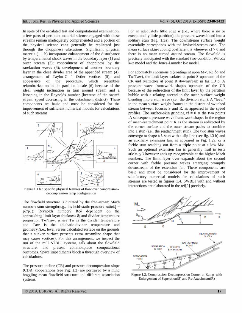
In spite of the escalated test and computational examination,
a few parts of pertinent material science engaged with these
streams remain inadequately comprehended and a portion of
the physical science can't generally be replicated just
through the choppiness alterations. Significant physical
marvels (1.1 b) incorporate enhancement of the disturbance
by temperamental shock waves in the boundary layer (1) and
outer stream (2); concealment of choppiness by the
rarefaction waves (3); development of another boundary
layer in the close divider area of the appended stream (4);
arrangement of Taylor-G ¨ Ortler vortices (5); and
appearance of the procedure, which resembles
relaminarization in the partition locale (6) because of the
ideal weight inclination in turn around stream and a
lessening in the Reynolds number (because of the switch
stream speed decreasing in the detachment district). These
components are basic and must be considered for the
improvement of sufficient numerical models for calculations
of such streams.
Figure 1.1 b : Specific physical features of flow over compression-
decompression ramp configuration
The flowfield structure is dictated by the free-stream Mach
number; stun strength(e.g., inviscid-static-pressure ratio(ξ =
p2/p1); Reynolds number2 Reδ dependent on the
approaching limit layer thickness δ; and divider temperature
proportion Tw/Taw, where Tw is the divider temperature
and Taw is the adiabatic-divider temperature and
geometry.(i.e., level versus calculated surface on the grounds
that a sunken surface presents extra streamline shape that
may cause vortices). For this arrangement, we inspect the
run of the mill STBLI systems, talk about the flowfield
structure, and present commonplace computational
outcomes. Space impediments block a thorough overview of
calculations.
The pressure incline (CR) and pressure decompression slope
(CDR) cooperations (see Fig. 1.2) are portrayed by a mind
boggling mean flowfield structure and different association
systems.
For an adequately little edge α (i.e., where there is no or
exceptionally little partition), the pressure waves blend into a
solitary stun (Fig. 1.3a). The downstream surface weight
essentially corresponds with the inviscid-stream case. The
mean surface skin-rubbing coefficient is wherever cf > 0 and
there is no mean turned around stream. The flowfield is
precisely anticipated with the standard two-condition Wilcox
k-ω model and the Jones-Launder k-ε model.
For adequately enormous α (contingent upon M∞, Re,δo and
Tw/Taw), the limit layer isolates at point S upstream of the
CR and reattaches at point R downstream in fig 1.3 b. A
pressure wave framework shapes upstream of the CR
because of the redirection of the limit layer by the partition
bubble with a relating ascend in the mean surface weight
blending into a stun wave (i.e., the division stun). A "level"
in the mean surface weight frames in the district of switched
stream between focuses S and R, as appeared in the speed
profiles. The surface-skin grinding cf = 0 at the two points
.A subsequent pressure wave framework shapes in the region
of mean-reattachment point R as the stream is redirected by
the corner surface and the outer stream packs to combine
into a stun (i.e., the reattachment stun). The two stun waves
converge to shape a λ-stun with a slip line (see fig.1.3 b) and
an auxiliary extension fan, as appeared in Fig. 1.2a, or a
feeble stun reaching out from a triple point at a low M∞.
Such an optional extension fan is generally frail in tests
atM∞ ≤ 3 however ends up recognizable at the higher Mach
numbers. The limit layer over expands about the second
corner with feeble pressure waves emerging promptly
downstream of the extension fan. These components are
basic and must be considered for the improvement of
satisfactory numerical models for calculations of such
streams are tested in figures 1.4. SWBLI with and without
interactions are elaborated in the ref[2] precisely.
Figure 1.2: Compression-Decompression Corner or Ramp with
Enlargement of Seperation(S) and Re-Attachment(R)

Int. J. Sci. Res. in Physics and Applied Sciences Vol.7 (5), Oct 2019, E-ISSN: 2348-3423
© 2019, IJSRPAS All Rights Reserved 18
Figure 1.3 a : Comparison between experiment and RANS with the
standard k-ω turbulence models for compression/decompression
ramp flow at smaller angle.
Figure 1.3b : Comparison between experiment and RANS with the
standard k-ω turbulence models for compression/decompression
ramp flow at higher angle.
Figure 1.4 : experimental schlieren images at two different instants
of time of interaction in Compression Ramp
II.TURBULENCE MODELS
The group of Reynolds-found the middle value of Navier-
Stokes (RANS) models is the biggest in the field of
choppiness. These models endeavor to close the disturbance
conditions utilizing thickness terms. A typical variable
determined in these models is k, or the dynamic vitality per
unit mass of fierce fluctuations.There are a few
confinements with RANS models as they depend on the
meaning of tempestuous thickness [8]. These impediments
are:
Absence of physical depiction
Disturbance initiated auxiliary streams
Streamlined arches
Whirling streams or streams with pivots
Transitional streams among tempestuous and laminar
Temperamental streams like inner burning motors
Dormant areas in streams
The possibility of unsettling influence and how it is
experimentally addressed in CFD reenactment tasks are
locked in with the pic 2.1 . Dividers are rule wellspring of
vorticity and unsettling influence and its quality offers climb
to brutal power and warm farthest point layers: definite
desire for frictional drag for external streams and weight
drop for inward channel streams endless supply of
neighborhood divider shear weight gauges. In this particular
condition, the grandiose assortments of field factors (speed,
temperature commercial weight) are in the uncommonly
close divider regions showed up by following picture.
The zone near the dividers is known as breaking point layer
and has also been disengaged into sub-layers. Unsettling
influence and farthest point layer are two immovably related
focuses. While as a rule stream is disengaged into two zones:
limit layer and free-stream, limit layers themselves are
isolated into 4 zones: gooey sub-layer, support layer, log-law
region and outside layer. Log-law region is in like manner
called "inertial sublayer". Outer layer is generally called
"disfigurement layer". Log-locale and inertial sublayer is
sometimes all things considered called "spread layer"
Usage of amazingly fine work to decide these shaky profiles
is in most of the applications computationally preposterously
expensive for utilization of CFD contraptions to the
mechanical scale. Along these lines, remarkable close
divider medications have been made since managing
conditions can't be fused down to divider. This incited the
progression of divider works and near divider treatment.
However, roughness isn't a heartbreaking thing under all
conditions. The image depicts the features of "brutal
developments" similarly as relatively few of the points of
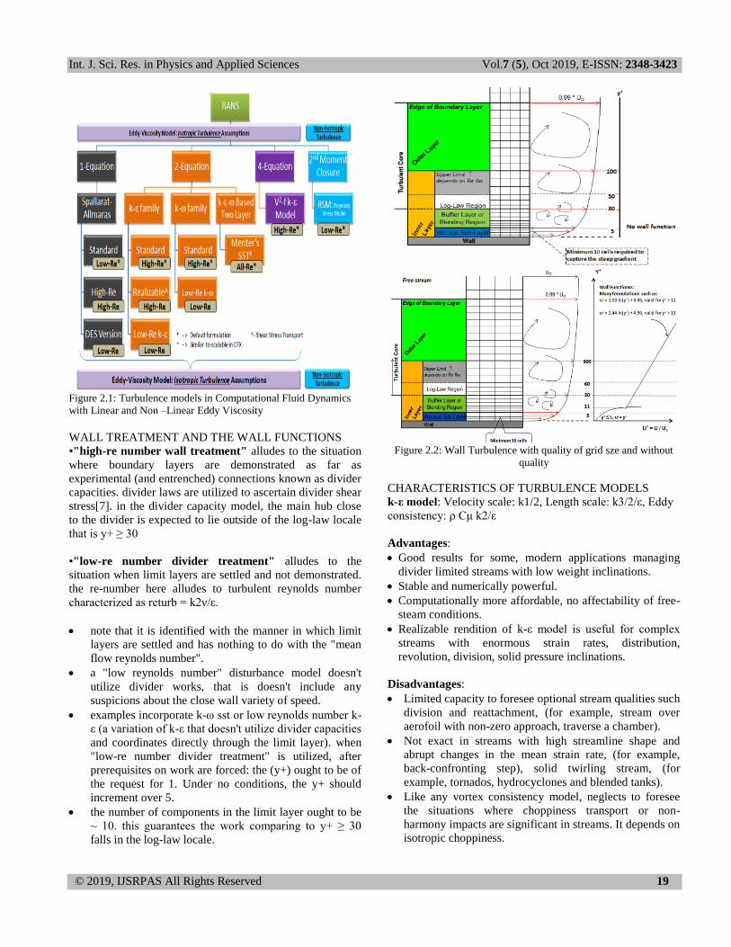
interest as well.2.1 Turbulence models in Computational
Fluid Dynamics
Int. J. Sci. Res. in Physics and Applied Sciences Vol.7 (5), Oct 2019, E-ISSN: 2348-3423
© 2019, IJSRPAS All Rights Reserved 19
Figure 2.1: Turbulence models in Computational Fluid Dynamics
with Linear and Non –Linear Eddy Viscosity
WALL TREATMENT AND THE WALL FUNCTIONS
•"high-re number wall treatment" alludes to the situation
where boundary layers are demonstrated as far as
experimental (and entrenched) connections known as divider
capacities. divider laws are utilized to ascertain divider shear
stress[7]. in the divider capacity model, the main hub close
to the divider is expected to lie outside of the log-law locale
that is y+ ≥ 30
•"low-re number divider treatment" alludes to the
situation when limit layers are settled and not demonstrated.
the re-number here alludes to turbulent reynolds number
characterized as returb = k2ν/ε.
note that it is identified with the manner in which limit
layers are settled and has nothing to do with the "mean
flow reynolds number".
a "low reynolds number" disturbance model doesn't
utilize divider works, that is doesn't include any
suspicions about the close wall variety of speed.
examples incorporate k-ω sst or low reynolds number k-
ε (a variation of k-ε that doesn't utilize divider capacities
and coordinates directly through the limit layer). when
"low-re number divider treatment" is utilized, after
prerequisites on work are forced: the (y+) ought to be of
the request for 1. Under no conditions, the y+ should
increment over 5.
the number of components in the limit layer ought to be
~ 10. this guarantees the work comparing to y+ ≥ 30
falls in the log-law locale.
Figure 2.2: Wall Turbulence with quality of grid sze and without
quality
CHARACTERISTICS OF TURBULENCE MODELS
k-ε model: Velocity scale: k1/2, Length scale: k3/2/ε, Eddy
consistency: ρ Cμ k2/ε
Advantages:
Good results for some, modern applications managing
divider limited streams with low weight inclinations.
Stable and numerically powerful.
Computationally more affordable, no affectability of free-
steam conditions.
Realizable rendition of k-ε model is useful for complex
streams with enormous strain rates, distribution,
revolution, division, solid pressure inclinations.
Disadvantages:
Limited capacity to foresee optional stream qualities such
division and reattachment, (for example, stream over
aerofoil with non-zero approach, traverse a chamber).
Not exact in streams with high streamline shape and
abrupt changes in the mean strain rate, (for example,
back-confronting step), solid twirling stream, (for
example, tornados, hydrocyclones and blended tanks).
Like any vortex consistency model, neglects to foresee
the situations where choppiness transport or non-
harmony impacts are significant in streams. It depends on
isotropic choppiness.

Int. J. Sci. Res. in Physics and Applied Sciences Vol.7 (5), Oct 2019, E-ISSN: 2348-3423
© 2019, IJSRPAS All Rights Reserved 20
Spalart-Allmaras model
Key qualities:
In standard structure, it is a Low-Re number model and
thus no divider capacity is utilized. That further forces a
limitations to have work fine enough so that y+ is < 1.0
all over the place.
Since this is a Low-Re number model, it very well may
be utilized with "Programmed Wall Treatment" or "All
y+ treatment" techniques for disturbance demonstrating.
This disturbance model had particularly been produced
for streamlined stream reproduction for airplane
business.
This models is a decent decision for applications where
the limit layers are generally joined and partition is
absent or gentle division is normal. Run of the mill
models would be stream over a wing, deliver frames,
rockets, fuselage or other aviation outside stream
applications.
The Spalart-Allmaras model for RANS conditions isn't
suggested for streams commanded by free-shear layers,
(for example, planes), streams where complex
distribution happens (particularly with warmth move)
and normal convection.
The Spalart-Allmaras models with DES can be utilized
for streams commanded by free-shear layers, (for
example, planes), streams where complex distribution
happens (particularly with warmth move) and common
convection.
Reynolds Stress Model (RSM) or Second Moment
Closure Methods
Key attributes:
Reynolds stresses are not demonstrated as Boussinesq
Hypothesis. In any case, displaying is as yet required for
some terms in the vehicle conditions.
Recommended for complex 3-D violent streams with
huge streamline ebb and flow and whirl, however the
model is computationally escalated, hard to meet than
vortex consistency models, for example, k-ε or Spalart-
Allmaras models.
Anisotropy of choppiness is represented, quadratic
weight strain choice improves execution for some,
essential shear streams.
Most reasonable for bended pipes state U or S-twists,
turning stream entries, combustors with huge bay twirl
and violent wind separators.
Standard k-ω Model (SKO): Velocity scale: k1/2, Length
scale: k1/2/Cμω, Eddy consistency: ρ k2/ω
Key qualities:
Specific scattering rate ω = k/ε understood rather than ε
Demonstrates better execution for divider limited and
low-Re streams and potential to deal with transitional
streams (however will in general foresee the progress
early).
Suitable for complex limit layer streams with
unfavorable weight slope and division (outer streamlined
features and turbomachinery).
Separation is ordinarily anticipated to be higher and
sooner than tentatively watched qualities.
Shear Stress Transport (SST) k-ω Model
Key attributes:
Specific dispersal rate ω = k/ε unraveled in inward layer
(log-layer and thick sub-layer) and advances to a k-ε
model away from the divider (however not same as
standard k-ε conditions).
The limit conditions for SST model are equivalent to the
k-ω model and is moderately less delicate to the free
stream estimation of ω.
Suitable for complex limit layer streams with unfriendly
pressure inclination and detachment (outer optimal
design and turbomachinery).
Enormous Eddy Simulation (LES):
Key qualities:
This model purposes all vortexes with scales bigger than
matrix scale and subsequently prescribed for wide-band
aeroacoustic commotion forecasts.
Time step size is administered when size of the littlest
settled whirlpools which requires the neighborhood
Courant-Friedrichs-Lewy (CFL) number to request of 1.
In ANSYS FLUENT, channel irritations at speed gulfs can
be forced while utilizing LES disturbance model.
FLUENT likewise prescribes "Limited Central
Differencing" for force if there should arise an occurrence
of LES on unstructured work.
III. PROBLEM DESCRIPTION
The geometry, shown schematically in Fig. 3.1 a, consists of
a Compression Corner with Four different Ramp deflection
angles of 15,18,21,24 Degrees. The strength of the shock
wave increases with surging the deflection angle
substantially , resulting in a stronger interaction with the
boundary layer. The inviscid shock from tip of shock
generator interacts with the turbulent boundary layer
developed over the flat plate. Free stream conditions are M∞
= 14.1, T∞ = 88.88K T(wall)=297.22 and p∞ = 1000 N/m2
with unit Reynolds number Re∞ = 37 × 106 m−1. The plate
is maintained under isothermal conditions of 300 K. Initially
the experiments were done for flow over flat plate to obtain
undisturbed turbulent boundary layer properties like δ, δ+, θ
and Cf at different locations. Wall data like pressure, skin
friction and heat transfer rates were measured along the flat
plate in the interaction region[6].

Int. J. Sci. Res. in Physics and Applied Sciences Vol.7 (5), Oct 2019, E-ISSN: 2348-3423
© 2019, IJSRPAS All Rights Reserved 21
The boundary conditions are identified in Fig.3.1b. Inlet
profiles for the computations are obtained from separate
Ramp simulation at freestream and wall boundary conditions
identical to those illustrated in the graphs. The value of the
momentum thickness reported in the experiments is matched
to obtain the mean flow and turbulence profiles at the inlet
boundary of the computational domain. The inlet profile for
the mean flow variables are modified at the shock entry
point to post-shock conditions calculated analyticallyin ref
[5]. Post-shock conditions are also prescribed at the top
boundary. At the wall, isothermal (Tw = 297.22 K), no-slip
boundary conditions are applied and extrapolation condition
is used at the exit boundary of the domain[5].
Fugure 3.1: Geometry of Compresion ramp with structural
mesh
Modeling and Meshing Here, I used a tool GAMBIT for modeling and meshing the
geometry as per parameters shown in Figure 3.1. During
meshing, I have maintained the quality of aspect ratio of
6.957. As a result, the model attained 127536 Quadrilateral
Cells, 254072 faces and 128537 Nodes as shown in Figure
3.1.
Analyzing There are umpteen software’s available for analyzing fluid
dynamic models among those FLUENT is the best tool to
make analysis easily. The main reason behind choosing
fluent is easy to use, Flexibility, Accuracy, allows for
efficient execution, interactive control, and complete
flexibility, for various operating systems.
CFL Variation
Different Courant-Friedrichs-Lewy (CFL) numbers are used
in the computations. In the computations, a CFL of 0.2 is
used at the beginning and it is gradually increased to 0.4 in
the first 200 iterations. It is further increased to 1.0 at 1000
iterations and to 5.0 at 5000 iterations, and to 6.0 at 8000
iteration. A maximum CFL of 7.0 is used after 10000
iterations. The Computation converges in 7-9 cpu hrs and it
takes 10000 iterations to reach the steady state solution.
IV. RESULTS AND DISCUSSION OF FLOW PHYSICS
In this work we have investigated two-dimensional Ramps
over wing-fold arrangements. Furthermore, streams over
hindrances whose setups are common of wing-fuselage point
geometries. These designs have been chosen with the target
to discover scaling laws to portray the neighborhood
wonders happening in the flowfield over a hypersonic
vehicle. Following the test investigations of Holden and
Delivery and Coet we have recognized some geometric and
stream parameters that influence the weight recuperation, the
partition and the warmth move rate, and have played out a
parametric report to assess their impact on the flowfield[4].
Specifically, the impacts of the incline edge (for example the
avoidance point of the control surface), the compass edge,
the main edge shape (through the variety of the span of arch
of the main edge) and the gooey and association parameter
have been precisely contemplated in Inviscid,Linear and
non-Linear swirl consistency models. For a large portion of
the two-dimensional calculations, we have played out a
lattice affectability concentrate to determine the impacts of
matrix goals on our discoveries. Be that as it may, we have
set up that a similar scaling laws hold both for two-
dimensional (for this situation freely of lattice goals)
arrangements as like three-dimensional ones; subsequently,
it is trusted that. in any event subjectively in ref [3]. The
discoveries for the three-dimensional case will remain. For
all experiments, we have first played out an examination to
Int. J. Sci. Res. in Physics and Applied Sciences Vol.7 (5), Oct 2019, E-ISSN: 2348-3423
© 2019, IJSRPAS All Rights Reserved 22
survey the significance of (conceivable) flimsiness impacts
through the angle of 15, 18, 21, and 24 degrees.
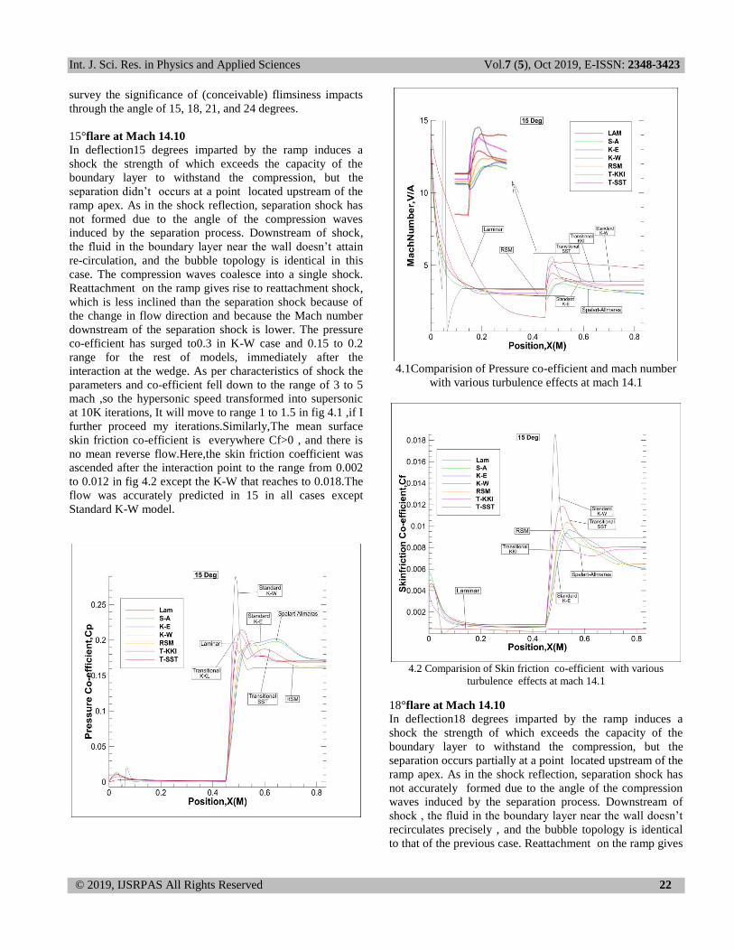
15°flare at Mach 14.10
In deflection15 degrees imparted by the ramp induces a
shock the strength of which exceeds the capacity of the
boundary layer to withstand the compression, but the
separation didn’t occurs at a point located upstream of the
ramp apex. As in the shock reflection, separation shock has
not formed due to the angle of the compression waves
induced by the separation process. Downstream of shock,
the fluid in the boundary layer near the wall doesn’t attain
re-circulation, and the bubble topology is identical in this
case. The compression waves coalesce into a single shock.
Reattachment on the ramp gives rise to reattachment shock,
which is less inclined than the separation shock because of
the change in flow direction and because the Mach number
downstream of the separation shock is lower. The pressure
co-efficient has surged to0.3 in K-W case and 0.15 to 0.2
range for the rest of models, immediately after the
interaction at the wedge. As per characteristics of shock the
parameters and co-efficient fell down to the range of 3 to 5
mach ,so the hypersonic speed transformed into supersonic
at 10K iterations, It will move to range 1 to 1.5 in fig 4.1 ,if I
further proceed my iterations.Similarly,The mean surface
skin friction co-efficient is everywhere Cf>0 , and there is
no mean reverse flow.Here,the skin friction coefficient was
ascended after the interaction point to the range from 0.002
to 0.012 in fig 4.2 except the K-W that reaches to 0.018.The
flow was accurately predicted in 15 in all cases except
Standard K-W model.
4.1Comparision of Pressure co-efficient and mach number
with various turbulence effects at mach 14.1
4.2 Comparision of Skin friction co-efficient with various
turbulence effects at mach 14.1
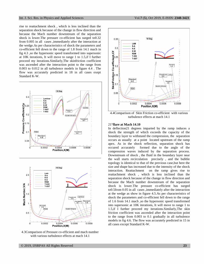
18°flare at Mach 14.10
In deflection18 degrees imparted by the ramp induces a
shock the strength of which exceeds the capacity of the
boundary layer to withstand the compression, but the
separation occurs partially at a point located upstream of the
ramp apex. As in the shock reflection, separation shock has
not accurately formed due to the angle of the compression
waves induced by the separation process. Downstream of
shock , the fluid in the boundary layer near the wall doesn’t
recirculates precisely , and the bubble topology is identical
to that of the previous case. Reattachment on the ramp gives
Int. J. Sci. Res. in Physics and Applied Sciences Vol.7 (5), Oct 2019, E-ISSN: 2348-3423
© 2019, IJSRPAS All Rights Reserved 23
rise to reattachment shock , which is less inclined than the
separation shock because of the change in flow direction and
because the Mach number downstream of the separation
shock is lower.The pressure co-efficient has surged to0.32
from 0.005 in all cases ,immediately after the interaction at
the wedge.As per characteristics of shock the parameters and
co-efficient fell down to the range of 1.8 from 14.1 mach in
fig 4.3 ,so the hypersonic speed transformed into supersonic
at 10K iterations, It will move to range 1 to 1.5,if I further
proceed my iterations.Similarly,The skinfriction coefficient
was ascended after the interaction point to the range from
0.003 to 0.012 in all turbulence models in figure 4.4 . The
flow was accurately predicted in 18 in all cases exept
Standard K-W.
4.3Comparison of Pressure co-efficient and mach number
with various turbulence effects at mach 14.1
4.4Comparison of Skin Friction co-efficient with various
turbulence effects at mach 14.1
21°flare at Mach 14.10
In deflection21 degrees imparted by the ramp induces a
shock the strength of which exceeds the capacity of the
boundary layer to withstand the compression, the separation
occurs as usually at a point located upstream of the ramp
apex. As in the shock reflection, separation shock has
occured accurately formed due to the angle of the
compression waves induced by the separation process.
Downstream of shock , the fluid in the boundary layer near
the wall starts recirculation precisely , and the bubble
topology is identical to that of the previous case,but here the
size and shape has increased due to the intensity of the shock
interaction. Reattachment on the ramp gives rise to
reattachment shock , which is less inclined than the
separation shock because of the change in flow direction and
because the Mach number downstream of the separation
shock is lower.The pressure co-efficient has surged
to0.5from 0.05 in all cases ,immediately after the interaction
at the wedge as show in figure 4.5.As per characteristics of
shock the parameters and co-efficient fell down to the range
of 1.6 from 14.1 mach ,so the hypersonic speed transformed
into supersonic at 10K iterations, It will move to range 1 to
1.5,if I further proceed my iterations.Similarly,The skin
friction coefficient was ascended after the interaction point
to the range from 0.003 to 0.1 gradually in all turbulence
models in fig 4.6. The flow was accurately predicted in 15 in
all cases except Standard K-W.

Int. J. Sci. Res. in Physics and Applied Sciences Vol.7 (5), Oct 2019, E-ISSN: 2348-3423
© 2019, IJSRPAS All Rights Reserved 24
4.5 Comparison of Pressure co-efficient and mach number with
various turbulence effects at mach 14.1
4.6 Comparison of Skin friction co-efficient with various
turbulence effects at mach 14.1
24°flare at Mach 14.10
In deflection24 degrees imparted by the ramp induces a
shock the strength of which exceeds the capacity of the
boundary layer to withstand the compression, the separation
occurs as usually at a point located upstream of the ramp
apex. As in the shock reflection, separation shock has
occurred precisely and completely formed due to the angle
of the compression waves induced by the separation process.
Downstream of shock , the fluid in the boundary layer near
the wall starts recirculation precisely , and the bubble
topology is identical to that of the previous case,but here the
size and shape has increased due to the intensity of the shock
interaction. Reattachment on the ramp gives rise to
reattachment shock , which is less inclined than the
separation shock because of the change in flow direction and
because the Mach number downstream of the separation
shock is lower. The pressure co-efficient has surged
to0.7from 0.1 in all cases ,immediately after the interaction
at the wedge.As per characteristics of shock the parameters
and co-efficient fell down to the range of 1.4 from 14.1
mach at fig 4.7 ,so the hypersonic speed transformed into
supersonic at 10K iterations, It will move to range to 1 to
1.3,if I further proceed my iterations.Similarly,The skin
friction coefficient was ascended after the interaction point
to the range from 0.05 to 0.12 gradually in all turbulence
models in fig 4.8. The flow was accurately predicted in 15 in
all cases except Standard K-W.

Int. J. Sci. Res. in Physics and Applied Sciences Vol.7 (5), Oct 2019, E-ISSN: 2348-3423
© 2019, IJSRPAS All Rights Reserved 25
4.7 Comparison of Pressure co-efficient and mach number with
various turbulence effects at mach 14.1
4.8 Comparison of Skin friction co-efficient with various
turbulence effects at mach 14.1
V. CONCLUSION
The point of this work was to assess the impact of some
geometrical and stream parameters on the highlights of two-
dimensional laminar and fierce hypersonic streams
overwhelmed by solid shockwave limit layer connections
with rather expanded isolated districts, and survey their
consequences for the streamlined exhibitions. It has been
discovered that, for streams over wing-fold and wing-
fuselage crossroads setups, parameters like incline and clear
points, driving edge obtuseness or thick communication
parameter strongly affect detachment, pressure recuperation
and warm loads. An about direct reliance of the upstream
impact with the fold diversion point has been anticipated; the
pinnacle warming has been found to associate with the
upstream impact by a power law reliance. Besides, the
upstream impact has been found to diminish straightly with
the comparability parameter, though a direct relationship
between's the drag coefficient, scaled by a similar parameter,
and the upstream impact has been built up.
REFERENCES
[1].Babinsky H, Harvey JK. “Shock-Wave Boundary Layer Interaction”,
Cambridge University, 1st edition.Page 151-159,166-169,268, 2011.
[2].Sravan Kumar Kota, P.V Subbaraju “Computational Analysis of Shockwave–Boundary Layer Interaction at Hypersonic
Speeds”,International Journal of Computer Aided Manufacturing, Vol.
5: Issue 2 Page 4-8,2019. [3]. V. Mikulla and C.C. “Horstmanj, “Turbulence Measurements in
Hypersonic Shock-Wave Boundary-Layer Interaction Flows”
American Institute of Aeronautics and Astronautics,Vol 14,No-5,Page 2-4.
[4].Sang Dug Kim,Chang oh Kwan, et al., “Comparision of turbulence
models in shockwave/Turbulent boundary layer interaction”KSME International Journal, Vol-18,No-1,PP-153-156,2004.
[5].Amjaed Ali Pasha, “Numerical prediction of shock/boundary-layer
interactions at high Mach numbers using a modified Spalart–Allmaras model” Engineering applications of computational fluid mechanics vol.
12, no. 1, page 459–472,2018.
[6]. F.Grassoand M. Marini, “Analysis of hypersonic shock-wave laminar boundary-layer interaction phenomena” Computers and fluids, Vol-
25,No-6,PP-561-581,1996.
[7]Stephen B .Pope, “Turbulent Flows”, Cornell University,Cambridege Series,1st Edition,Pages:359-406,2000.
[8] H .Tennekes, J.L Lumley, “A first course in Turbulence” The
Massachusetts Institute of Technology Press,1st edition, pages:7-11,52-57,1972
Authors Profile
Sravankumar Kota completed his Master of
Technology in the field of Aerospace Engineering
under Jawaharlal Nehru Technological University
and Bachelor of Engineering in the field of
Aeronautical Engineering at Anna University,
Chennai. He is an Associate and Professional
member of various International organizations like
IRED, IME, NSPE, IAE and so forth. He is currently serving as
Lead Design Engineer at Samhams Technologies, Chennai branch.
His main research work focus on Aerodynamics, Fluid Dynamics,
Hypersonics, Computational Fluid Dynamics, Heat Transfer,
Advanced Turbulence Models, Unsteady Flows, Species Transport
Phenomena, Propulsion, Scramjet & Shcramjet, Shock Wave
boundary layer Interaction, and Optimization.
Mohammad Shahid is an Assistant Professor in
Aeronautical Department at Rajasthan Technical
University, Kota, Having worked there since
2015.He had received his Masters Aerospace
engineering at Jawaharlal Nehru Technological
University and Bachelors Aerospace Engineering
at University of Petroleum and Energy Studies
,Dehradun. His research includes, Computational Fluid Dynamics,
Aircraft Stuctures, Finite Element methods, Composite materials


