1
Lifting Flow over a Cylinder as a Lift System
By Kyle Mello
Kennesaw State University (August 2020)
Abstract
The goal of this project is to conceptually design a lift system consisting of rotating cylinders
that may improve certain flight characteristics when compared to conventional wings for a
typical two passenger airplane. The functions of flaps, ailerons, lift to weight ratio and
structural responses are considered. The cylindrical model is developed within CFD simulation
software such that it generates the same lift produced by the wings of a Cessna 172 wings at
cruising speed. Incompressible flow theoretical solutions are initially shown to compare
favorably with the computational predictions for elementary cylindrical designs.
The rotating cylinder aircraft generates the same lift as a Cessna 172 flying at 40m/s at an angle
of attack of 2.5 degrees. Theoretical calculations and CFD simulation both show the rotating
cylinders to generate a lift to weight ratio of 27.2, compared to the Cessna’s 7.58. The main
concern of this dynamic lift system is its structural integrity under constant rotation. At
rotational speeds up to 350rad/s, the cylinders are well within their structural limits of resisting
hoop and shear stresses.
A dual shaft electric motor is used to power the cylinders to generate lift. The ailerons are
replaced by using eddy current brakes to slow down the rotational speed of one of the cylinders,
causing the aircraft to roll. The flaps are replaced by simply increasing the rotational speed of
the cylinders.
1. Introduction A rotating cylinder in a uniform flow directs the air downwards which produces lift
according to Newton’s 3rd Law. This is a phenomenon known as the Magnus Effect. Rotating
cylinders are known to be able to produce large amounts of lift and have been utilized in multiple
aircrafts and boats.
Anton Flettner, a German engineer, was one of the first engineers to use the Magnus
Effect to power a vehicle. He created a boat in 1925 with two large vertical cylinders which
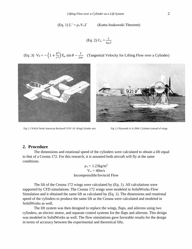
propelled the ship. In 1930, American investors created one of the first planes (Plymouth A-A-
2004) that used cylinders instead of wings. The Plymouth A-A-2004 reportedly made two
successful flights until the project was disbanded. Since then, there have been many aircraft that
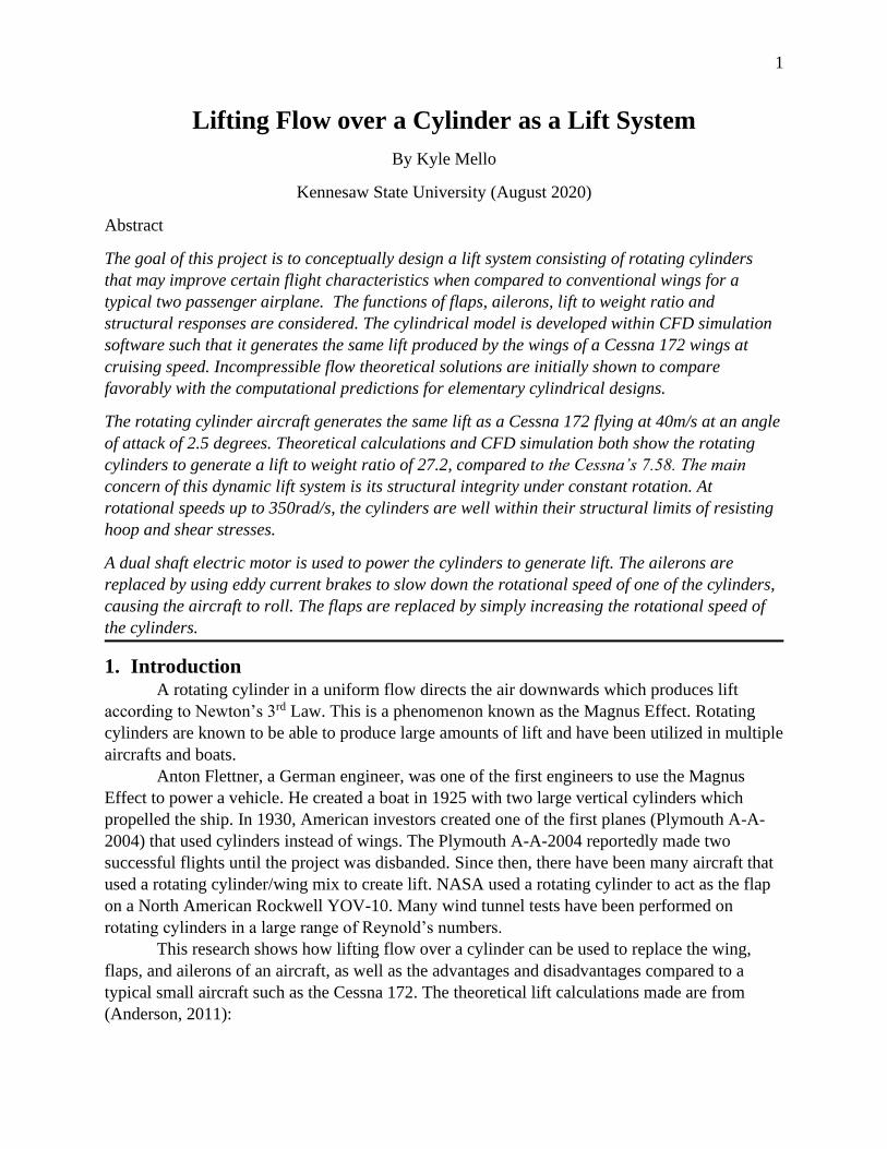
used a rotating cylinder/wing mix to create lift. NASA used a rotating cylinder to act as the flap
on a North American Rockwell YOV-10. Many wind tunnel tests have been performed on
rotating cylinders in a large range of Reynold’s numbers.
This research shows how lifting flow over a cylinder can be used to replace the wing,
flaps, and ailerons of an aircraft, as well as the advantages and disadvantages compared to a
typical small aircraft such as the Cessna 172. The theoretical lift calculations made are from
(Anderson, 2011):
Lifting Flow over a Cylinder as a Lift System 2
(Eq. 1) L’ = ρ∞V∞Γ (Kutta-Joukowski Theorem)
(Eq. 2) CL = 𝐿
𝑞∞𝑆
(Eq .3) Vθ = −(1 +𝑅2
𝑟2) 𝑉∞ sin 𝜃 −
Γ
2𝜋𝑟 (Tangential Velocity for Lifting Flow over a Cylinder)
Fig 1.1 NASA North American Rockwell YOV-10. Wing/Cylinder mix. Fig 1.2 Plymouth A-A-2004. Cylinders instead of wings
2. Procedure The dimensions and rotational speed of the cylinders were calculated to obtain a lift equal
to that of a Cessna 172. For this research, it is assumed both aircraft will fly at the same
conditions.
ρ∞ = 1.23kg/m3
V∞ = 40m/s
Incompressible/Inviscid Flow
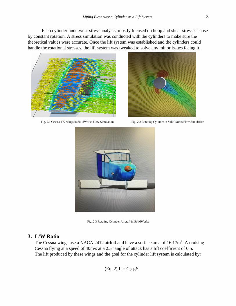
The lift of the Cessna 172 wings were calculated by (Eq. 1). All calculations were
supported by CFD simulations. The Cessna 172 wings were modeled in SolidWorks Flow
Simulation and it obtained the same lift as calculated by (Eq. 1). The dimensions and rotational
speed of the cylinders to produce the same lift as the Cessna were calculated and modeled in
SolidWorks as well.
The lift system was then designed to replace the wings, flaps, and ailerons using two
cylinders, an electric motor, and separate control systems for the flaps and ailerons. This design
was modeled in SolidWorks as well. The flow simulations gave favorable results for the design
in terms of accuracy between the experimental and theoretical lifts.
Lifting Flow over a Cylinder as a Lift System 3
Each cylinder underwent stress analysis, mostly focused on hoop and shear stresses cause
by constant rotation. A stress simulation was conducted with the cylinders to make sure the
theoretical values were accurate. Once the lift system was established and the cylinders could
handle the rotational stresses, the lift system was tweaked to solve any minor issues facing it.
Fig. 2.1 Cessna 172 wings in SolidWorks Flow Simulation Fig. 2.2 Rotating Cylinder in SolidWorks Flow Simulation
Fig. 2.3 Rotating Cylinder Aircraft in SolidWorks
3. L/W Ratio The Cessna wings use a NACA 2412 airfoil and have a surface area of 16.17m2. A cruising
Cessna flying at a speed of 40m/s at a 2.5° angle of attack has a lift coefficient of 0.5.
The lift produced by these wings and the goal for the cylinder lift system is calculated by:
(Eq. 2) L = CLq∞S
Lifting Flow over a Cylinder as a Lift System 4
Where q∞ = dynamic pressure
S = surface area
In an incompressible and inviscid flow, the lift produced by the Cessna wings at V = 40m/s
and α = 2.5° is equal to 7956N.
Goal Lift = 7956N
The dimensions and rotational speed of the cylinders to produce this same lift is calculated
by the Kutta-Joukowski Theorem (Eq. 1) and the equation for the tangential velocity of
lifting flow over a cylinder (Eq. 3).
(Eq. 1) L = ρ∞V∞Γ(Length) = 7956N / 2 = 3978N
(Eq. 3) Vθ = −(1 +𝑅2
𝑟2) 𝑉∞ sin 𝜃 −
Γ
2𝜋𝑟
There is an infinite amount of combinations of radii, lengths, thickness, and rotational speeds
that could obtain this certain lift; however, each combination has a unique L/W ratio and
experiences different stresses. The chosen values were
r = 0.224m
length = 1m
ω = 256rad/s
t = 0.00381m
These values produced a large L/W ratio and also experience a relatively small amount of
stress which will be shown in section 5.
The wings of a Cessna 172 weigh 1050.2N. Given the above conditions, the L/W ratio of the
Cessna wings is 7.58.
The material chosen for the rotating cylinder lift system is 2014-T6 Aluminum (shown in
section 5). The density is 2800kg/m3. Given the dimensions of the cylinders, the L/W ratio is
27.2.
Cessna 172 L/W = 7.58
Rotating Cylinder L/W = 27.2
The cylinders themselves produce a significantly larger L/W ratio than the wings;
however, this number only includes the weight of the cylinders. The cylinders require a fairly
small electric motor and control system that will decrease the L/W ratio. Given that the
rotational speed of the cylinders is going to be nearly constant during flight, the motor does
not need to be incredibly powerful. A motor capable of powering this system should be no
more than 80 pounds since gears can be used to increase the angular velocity of the cylinders.
Lifting Flow over a Cylinder as a Lift System 5
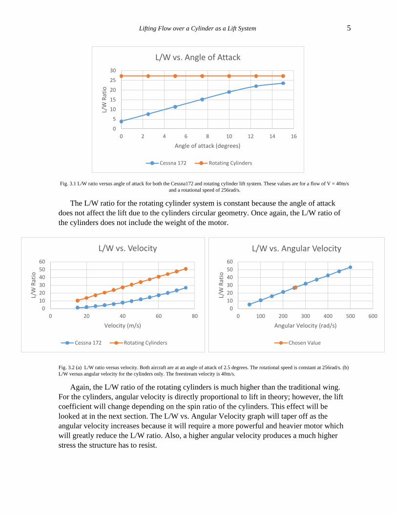
Fig. 3.1 L/W ratio versus angle of attack for both the Cessna172 and rotating cylinder lift system. These values are for a flow of V = 40m/s
and a rotational speed of 256rad/s.
The L/W ratio for the rotating cylinder system is constant because the angle of attack
does not affect the lift due to the cylinders circular geometry. Once again, the L/W ratio of
the cylinders does not include the weight of the motor.
Fig. 3.2 (a) L/W ratio versus velocity. Both aircraft are at an angle of attack of 2.5 degrees. The rotational speed is constant at 256rad/s. (b)
L/W versus angular velocity for the cylinders only. The freestream velocity is 40m/s.
Again, the L/W ratio of the rotating cylinders is much higher than the traditional wing.
For the cylinders, angular velocity is directly proportional to lift in theory; however, the lift
coefficient will change depending on the spin ratio of the cylinders. This effect will be
looked at in the next section. The L/W vs. Angular Velocity graph will taper off as the
angular velocity increases because it will require a more powerful and heavier motor which
will greatly reduce the L/W ratio. Also, a higher angular velocity produces a much higher
stress the structure has to resist.
0
5
10
15
20
25
30
0 2 4 6 8 10 12 14 16
L/W
Rat
io
Angle of attack (degrees)
L/W vs. Angle of Attack
Cessna 172 Rotating Cylinders
0
10
20
30
40
50
60
0 20 40 60 80
L/W
Rat
io
Velocity (m/s)
L/W vs. Velocity
Cessna 172 Rotating Cylinders
0
10
20
30
40
50
60
0 100 200 300 400 500 600
L/W
Rat
io
Angular Velocity (rad/s)
L/W vs. Angular Velocity
Chosen Value
Lifting Flow over a Cylinder as a Lift System 6
A typical airplane needs a very high angle of attack to compete with the L/W ratio of the
cylinder system. An airplane flying at this high of an angle will experience a huge amount of
drag, however. The L/W ratio produced by the cylinders is significantly better than the
Cessna 172 assuming incompressible and inviscid flow.
4. Efficiency of Rotating Cylinders The lift coefficient of the rotating cylinders strongly depends on the spin ratio and the
Reynold’s number. The spin ratio and Reynold’s number are defined as:
(Eq. 4) a = 𝜔𝑟
𝑉∞
(Eq. 5) Re = 𝑉∞𝐷
𝜈 where ν is the kinematic viscosity of the air
It is the ratio the cylinder is spinning compared to the freestream velocity. A higher spin ratio
results in a more efficient lift coefficient. A good representation of this is shown by
(Karabelas, et al, 2012) in the figure below.
Lifting Flow over a Cylinder as a Lift System 7
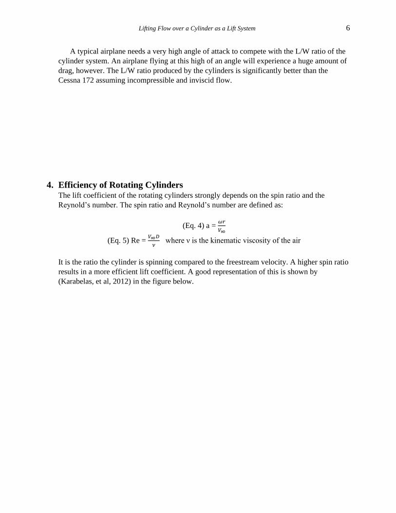
Fig. 4.1 Flow as it depends on the Reynold’s number and the spin ratio. Note that the cylinders are spinning “into the air,” directing the flow
upwards instead of downwards. (Credit Karabelas et al. “High Reynold’s Number Turbulent Flow Past a Rotating Cylinder”)
At spin ratios close to zero, the cylinders do not direct the air enough to produce a
significant amount of lift. A higher spin ratio results in a more efficient lift coefficient. For
the chosen dimensions and angular velocity of the cylinders result in a spin ratio of 1.43. This
ratio will produce a decent lift coefficient. As the spin ratio increase, the stresses increase. A
fairly small spin ratio is required in this aircraft in order to maintain longevity of the
aluminum.
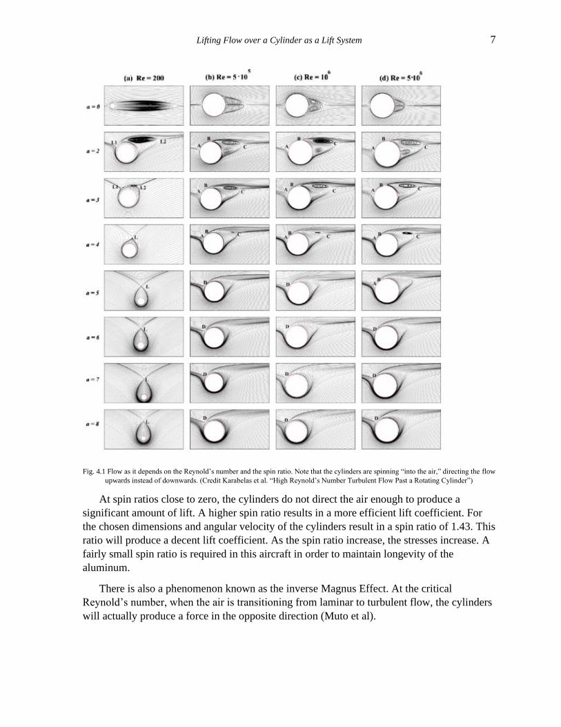
There is also a phenomenon known as the inverse Magnus Effect. At the critical
Reynold’s number, when the air is transitioning from laminar to turbulent flow, the cylinders
will actually produce a force in the opposite direction (Muto et al).
Lifting Flow over a Cylinder as a Lift System 8
Fig. 4.2 Inverse Magnus Effect. (Credit Kundu, et al. 2016. “Boundary Layers and Related Topics”).
The rotating cylinder aircraft will have a Reynold’s number of Re = 1.19*106. The
critical Reynold’s number over a circular cylinder occurs at 2.50*105 – 3.50*105. The aircraft
will only experience the inverse Magnus Effect before takeoff so it will not affect
performance in any way. For cylinders with radii of 0.224m, the aircraft has to be traveling
less than 11m/s to experience the inverse Magnus Effect. This would only occur on the
ground.
Theoretically, lifting flow over a cylinder in an incompressible and inviscid flow
experiences no drag (Anderson, 2011). This is not the case in real life, however. There is a
large amount of drag coefficient data for rotating cylinders available. However, at high
Reynold’s numbers, the values are incredibly inconsistent. Therefore, more wind tunnel tests
need to be conducted for rotating cylinders to accurately compare the L/D ratios for a wing
and the rotating cylinders.
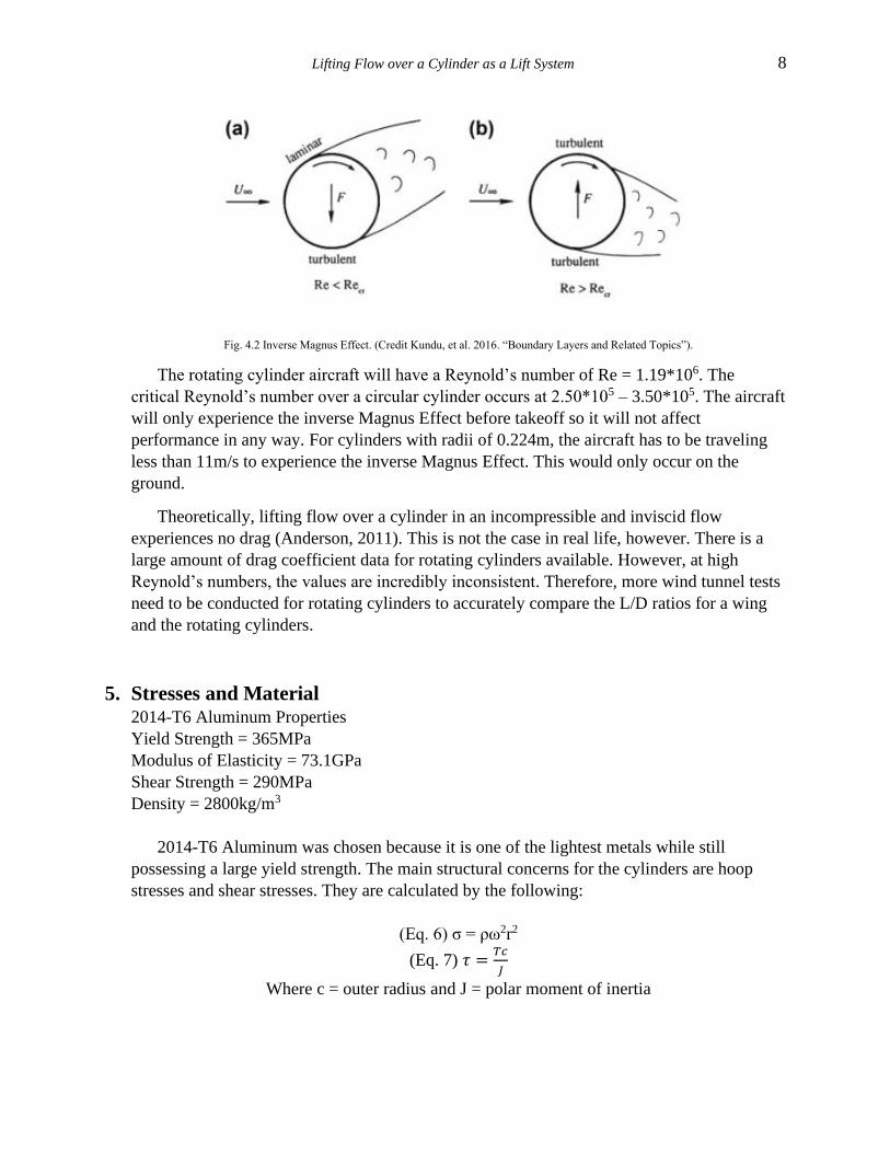
5. Stresses and Material 2014-T6 Aluminum Properties
Yield Strength = 365MPa
Modulus of Elasticity = 73.1GPa
Shear Strength = 290MPa
Density = 2800kg/m3
2014-T6 Aluminum was chosen because it is one of the lightest metals while still
possessing a large yield strength. The main structural concerns for the cylinders are hoop
stresses and shear stresses. They are calculated by the following:
(Eq. 6) σ = ρω2r2
(Eq. 7) 𝜏 =𝑇𝑐
𝐽
Where c = outer radius and J = polar moment of inertia
Lifting Flow over a Cylinder as a Lift System 9
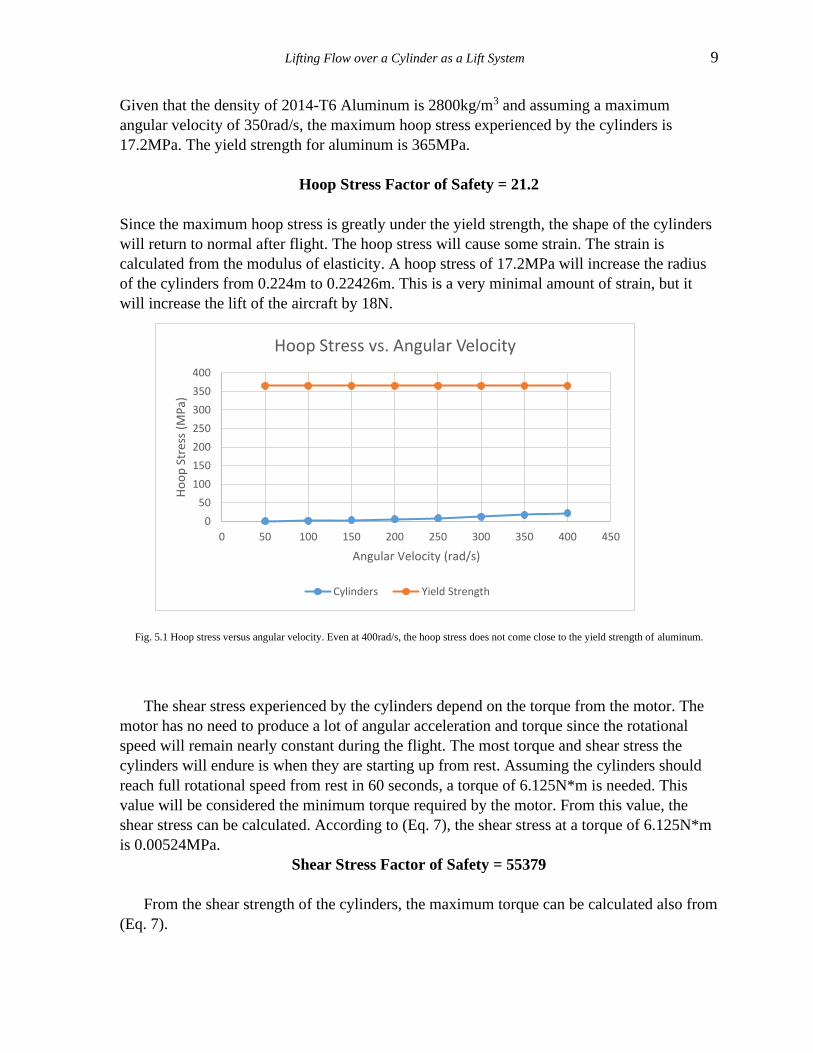
Given that the density of 2014-T6 Aluminum is 2800kg/m3 and assuming a maximum
angular velocity of 350rad/s, the maximum hoop stress experienced by the cylinders is
17.2MPa. The yield strength for aluminum is 365MPa.
Hoop Stress Factor of Safety = 21.2
Since the maximum hoop stress is greatly under the yield strength, the shape of the cylinders
will return to normal after flight. The hoop stress will cause some strain. The strain is
calculated from the modulus of elasticity. A hoop stress of 17.2MPa will increase the radius
of the cylinders from 0.224m to 0.22426m. This is a very minimal amount of strain, but it
will increase the lift of the aircraft by 18N.
Fig. 5.1 Hoop stress versus angular velocity. Even at 400rad/s, the hoop stress does not come close to the yield strength of aluminum.
The shear stress experienced by the cylinders depend on the torque from the motor. The
motor has no need to produce a lot of angular acceleration and torque since the rotational
speed will remain nearly constant during the flight. The most torque and shear stress the
cylinders will endure is when they are starting up from rest. Assuming the cylinders should
reach full rotational speed from rest in 60 seconds, a torque of 6.125N*m is needed. This
value will be considered the minimum torque required by the motor. From this value, the
shear stress can be calculated. According to (Eq. 7), the shear stress at a torque of 6.125N*m
is 0.00524MPa.
Shear Stress Factor of Safety = 55379
From the shear strength of the cylinders, the maximum torque can be calculated also from
(Eq. 7).
0
50
100
150
200
250
300
350
400
0 50 100 150 200 250 300 350 400 450
Ho
op
Str
ess
(MP
a)
Angular Velocity (rad/s)
Hoop Stress vs. Angular Velocity
Cylinders Yield Strength
Lifting Flow over a Cylinder as a Lift System 10
290MPa = 𝑇𝑚𝑎𝑥(0.224𝑚)
0.000262𝑚4
Maximum Torque = 339196N*m
The torque produced by the motor will be well within the torque range, but much closer to
the minimum end. The shear stress experienced by the cylinders will result in a minuscule
deformation.
A rotational stress analysis simulation was performed for both hoop stress and shear
stress. The simulation produced results +/-1% of the theoretical calculations.
6. Design The aircraft will have the same fuselage, tail, engine, and propeller as the Cessna 172.
The rotating cylinders will replace the wings.
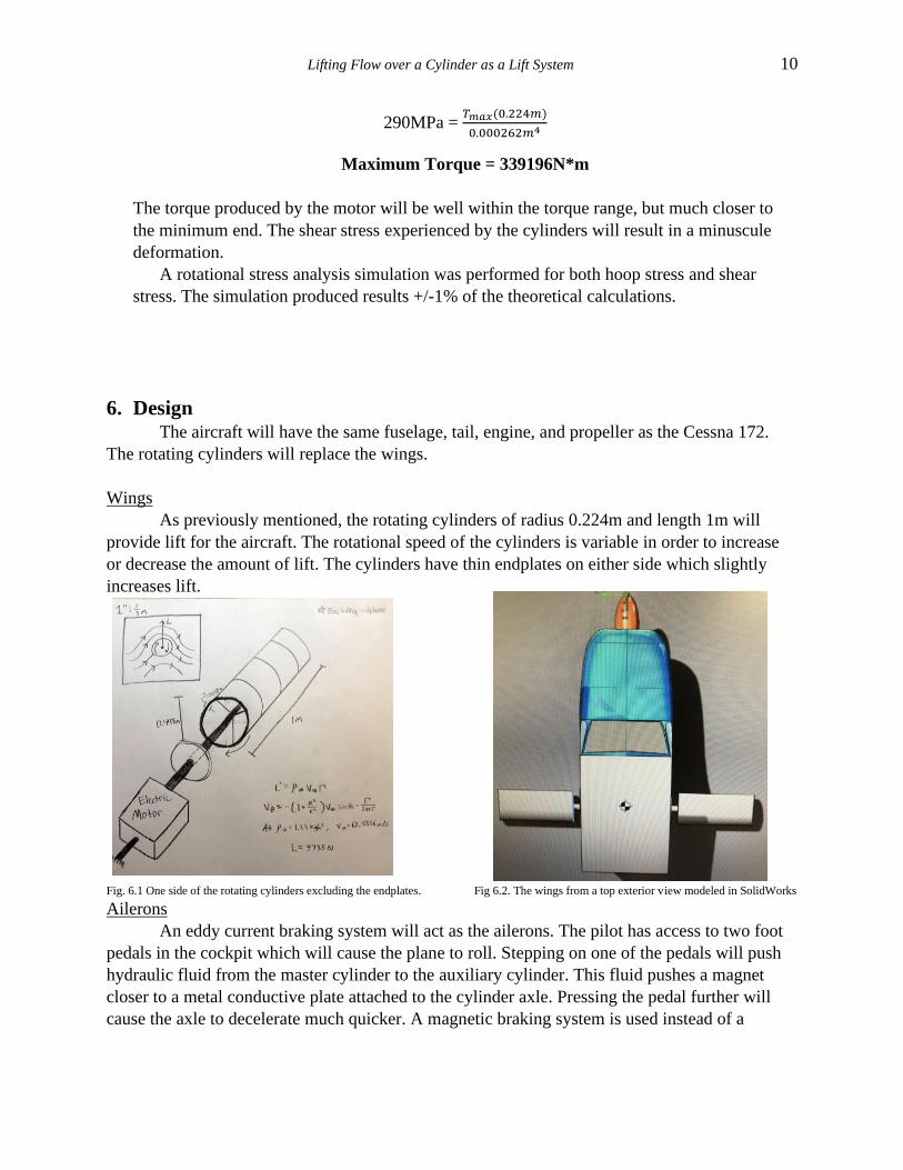
Wings
As previously mentioned, the rotating cylinders of radius 0.224m and length 1m will
provide lift for the aircraft. The rotational speed of the cylinders is variable in order to increase
or decrease the amount of lift. The cylinders have thin endplates on either side which slightly
increases lift.
Fig. 6.1 One side of the rotating cylinders excluding the endplates. Fig 6.2. The wings from a top exterior view modeled in SolidWorks
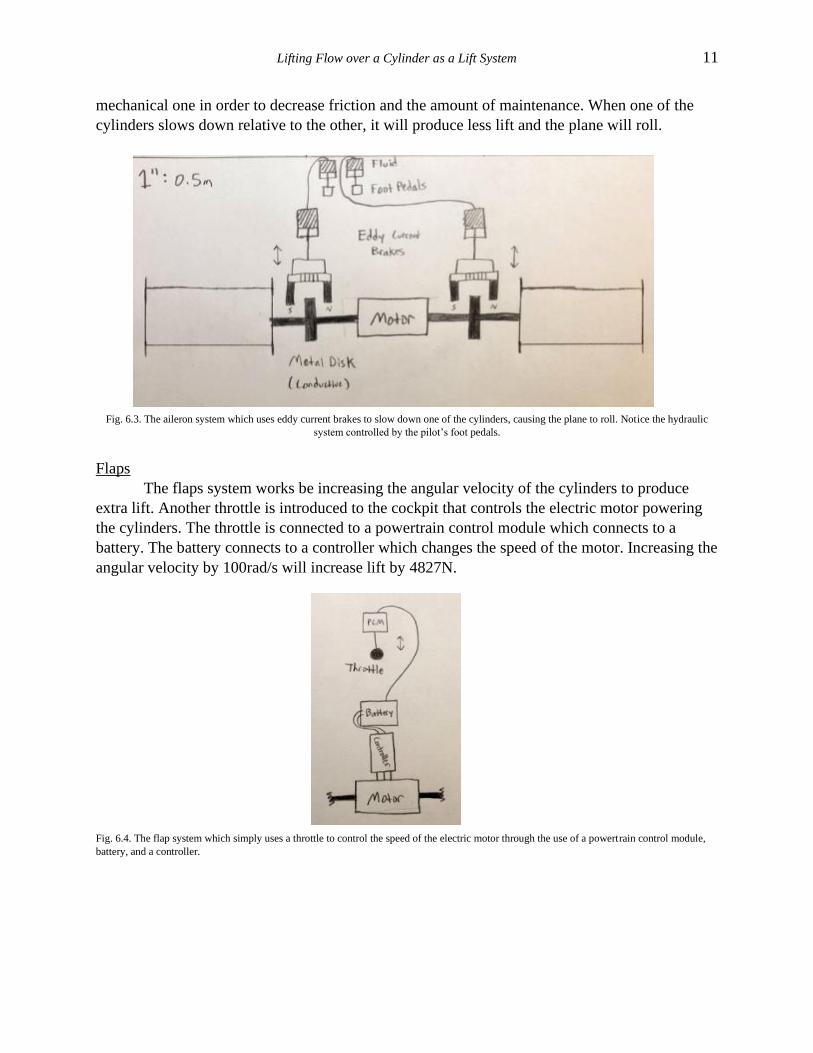
Ailerons
An eddy current braking system will act as the ailerons. The pilot has access to two foot
pedals in the cockpit which will cause the plane to roll. Stepping on one of the pedals will push
hydraulic fluid from the master cylinder to the auxiliary cylinder. This fluid pushes a magnet
closer to a metal conductive plate attached to the cylinder axle. Pressing the pedal further will
cause the axle to decelerate much quicker. A magnetic braking system is used instead of a
Lifting Flow over a Cylinder as a Lift System 11
mechanical one in order to decrease friction and the amount of maintenance. When one of the
cylinders slows down relative to the other, it will produce less lift and the plane will roll.
Fig. 6.3. The aileron system which uses eddy current brakes to slow down one of the cylinders, causing the plane to roll. Notice the hydraulic
system controlled by the pilot’s foot pedals.
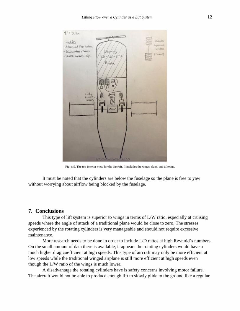
Flaps
The flaps system works be increasing the angular velocity of the cylinders to produce
extra lift. Another throttle is introduced to the cockpit that controls the electric motor powering
the cylinders. The throttle is connected to a powertrain control module which connects to a
battery. The battery connects to a controller which changes the speed of the motor. Increasing the
angular velocity by 100rad/s will increase lift by 4827N.
Fig. 6.4. The flap system which simply uses a throttle to control the speed of the electric motor through the use of a powertrain control module,
battery, and a controller.
Lifting Flow over a Cylinder as a Lift System 12
Fig. 6.5. The top interior view for the aircraft. It includes the wings, flaps, and ailerons.
It must be noted that the cylinders are below the fuselage so the plane is free to yaw
without worrying about airflow being blocked by the fuselage.
7. Conclusions This type of lift system is superior to wings in terms of L/W ratio, especially at cruising
speeds where the angle of attack of a traditional plane would be close to zero. The stresses
experienced by the rotating cylinders is very manageable and should not require excessive
maintenance.
More research needs to be done in order to include L/D ratios at high Reynold’s numbers.
On the small amount of data there is available, it appears the rotating cylinders would have a
much higher drag coefficient at high speeds. This type of aircraft may only be more efficient at
low speeds while the traditional winged airplane is still more efficient at high speeds even
though the L/W ratio of the wings is much lower.
A disadvantage the rotating cylinders have is safety concerns involving motor failure.
The aircraft would not be able to produce enough lift to slowly glide to the ground like a regular
Lifting Flow over a Cylinder as a Lift System 13
plane. Since rotating cylinders are used on a small aircraft, this problem can be solved by
employing a parachute in the top of the fuselage, such as how a rocket capsule employs a
parachute when returning to Earth. The aircraft will be much lighter than a rocket capsule so he
parachute will not need to weigh as much.
Software simulations were used to support and confirm the theoretical calculations. In an
incompressible, inviscid flow at low speeds, the rotating cylinder lift system appears to be
plausible and significantly more efficient than wings regarding L/W ratio. The efficiency of an
aircraft with rotating cylinders relies on the motor. A motor with a very high power to weight
ratio will increase the L/W efficiency of the aircraft. Depending on the use of the aircraft, gear
ratios can be adjusted to increase the angular velocity of the cylinders without adding much
weight to the system.
References
Achenbach, E. (1972). Experiments on the flow past spheres at very high Reynolds numbers. Journal of
Fluid Mechanics, 54(3), 565-575.
Anderson, Jr., John D. Fundamentals of Aerodynamics. 5th ed., McGraw-Hill Education, 2011.
Asrokin, Azharrudin & Ramly, Mohammad & Ahmad, Abdul. (2013). Rotating cylinder design as a
lifting generator. IOP Conference Series: Materials Science and Engineering. 50. 10.1088/1757-
899X/50/1/012025.
Cichy, D. R., Harris, J. W., & MacKay, J. K. (1972). Flight tests of a rotating cylinder flap on a North
American Rockwell YOV-10 aircraft.
“Flow Past a Circular Cylinder from Critical to Trans-Critical Reynolds Numbers.” Flow Past a
Circular Cylinder from Critical to Trans-Critical Reynolds Numbers | Heat and Mass Transfer
Technological Center (CTTC)-Universitat Politècnica De Catalunya BARCELONA TECH
(UPC), Centre Tecnologic De Transferencia De Calor Universitat Politecnica De Catalunya,
www.cttc.upc.edu/node/139.
Karabelas S.J., Koumroglou B.C., Argyropoulos C.D., Markatos N.C.
(2012). High Reynolds number turbulent flow past a rotating cylinder. Applied Mathematical
Modelling, 36 (1) , pp. 379-398.
Kim, J., Choi, H., Park, H., & Yoo, J. (2014). Inverse Magnus effect on a rotating sphere: When and
why. Journal of Fluid Mechanics, 754, R2. doi:10.1017/jfm.2014.428
Kundu, Pijush K., et al. Fluid Mechanics. 6th ed., Academic Press, 2016.
“Lift of a Rotating Cylinder.” NASA, Glenn Research Center, 5 Apr. 2018, www.grc.nasa.gov/WWW/K-
12/airplane/cyl.html#:~:text=The%20lift%20equation%20for%20a,is%20established%20by%20t
he%20rotation.
Lifting Flow over a Cylinder as a Lift System 14
Muto, M., Watanabe, H., Tsubokura, M., & Oshima, N. (2011, December). Negative magnus effect on a
rotating sphere at around the critical reynolds number. In Journal of Physics: Conference
Series (Vol. 318, No. 3, p. 032021). IOP Publishing Ltd..
Reid, Elliott G. Tests of rotating cylinders, report, December
1924; (https://digital.library.unt.edu/ark:/67531/metadc53882/: accessed August 6,
2020), University of North Texas Libraries, UNT Digital Library, https://digital.library.unt.edu;
crediting UNT Libraries Government Documents Department.
Tokumaru, P., & Dimotakis, P. (1993). The lift of a cylinder executing rotary motions in a uniform
flow. Journal of Fluid Mechanics, 255, 1-10. doi:10.1017/S0022112093002368


