
Lecture 6 (06.08.12):
Theory of Multi-view Orthographic
Projections
Dr. Sharad Gokhale
Civil Engineering Department, IIT Guwahati
208, M-Block, Academic Complex
Email: [email protected]
Telephone #: 2419

Multi-view Orthographic
ProjectionsProjections
Terms and definition
• Projection – image or the act of obtaining an
image of an object
• In technical drawing – we call it a view
• Method – we use projection method to obtain • Method – we use projection method to obtain
a view of an object
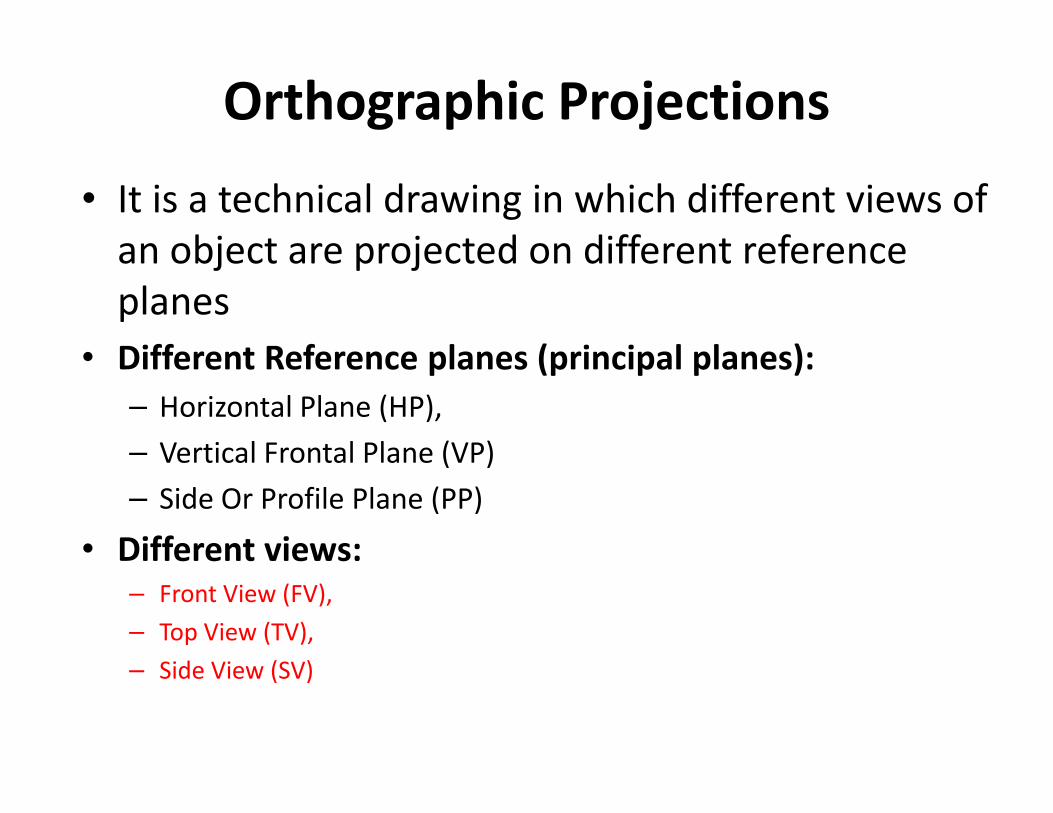
Orthographic Projections
• It is a technical drawing in which different views of
an object are projected on different reference
planes
• Different Reference planes (principal planes):
– Horizontal Plane (HP),– Horizontal Plane (HP),
– Vertical Frontal Plane (VP)
– Side Or Profile Plane (PP)
• Different views:
– Front View (FV),
– Top View (TV),
– Side View (SV)
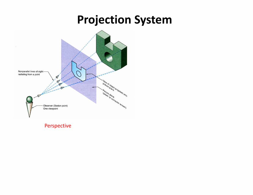
Projection System
Perspective

Projection System
Projection lines
Plane of Projections (POP)
Perspective
Parallel

Projection System
Projection lines
Plane of Projections (POP)
Perspective (Convergent
projection)
Parallel Projection
Three basic elements:
i. Object
ii. Observer
iii. POP

Projection of an ObjectProjection of an ObjectThe outline on the plane of projection shows how the object appears to the
observer. In orthographic projection, projections from all points of the
object extend parallel to each other and perpendicular to the plane ofprojection.

X
Y
X

X
Y
1st Quad.2nd Quad.
X Y
VP
HP
Observer
X
3rd Quad. 4th Quad.
This quadrant pattern,
If observed along x-y line ( in red arrow direction) will exactly appear as shown on
right side and hence, It is further used to understand illustration properly.
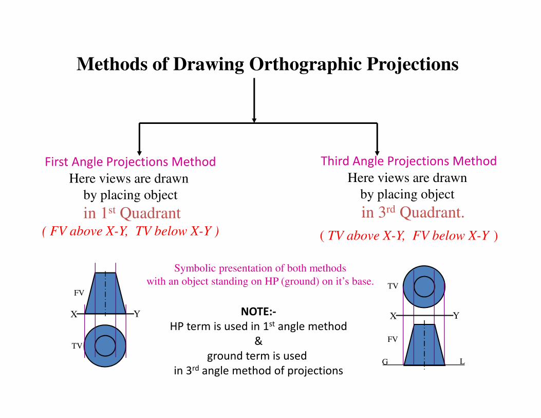
Methods of Drawing Orthographic Projections
First Angle Projections Method
Here views are drawn
by placing object
in 1st Quadrant
Third Angle Projections Method
Here views are drawn
by placing object
in 3rd Quadrant. in 1st Quadrant( FV above X-Y, TV below X-Y )
in 3rd Quadrant.
( TV above X-Y, FV below X-Y )
FV
TV
X Y X Y
G L
TV
FV
Symbolic presentation of both methods
with an object standing on HP (ground) on it’s base.
NOTE:-
HP term is used in 1st angle method
&
ground term is used
in 3rd angle method of projections

Planes
PRINCIPAL PLANES
HP AND VP
AUXILIARY PLANES
Profile Plane (P.P.)
A.V.P.
⊥ to HP & ∠ to VP
Auxiliary Vertical Plane
(A.V.P.)Auxiliary Inclined Plane
(A.I.P.)

This is a pictorial set-up of all three planes. Arrow direction is a
normal way of observing the object. But in this direction only VP and a
view on it (FV) can be seen. The other planes and views on those can
not be seen.
Procedure to solve above problem:-
To make those planes also visible from the arrow direction,
i) HP is rotated 900 downward, ii) PP, 900 in right side direction.
This way both planes are brought in the same plane containing VP.
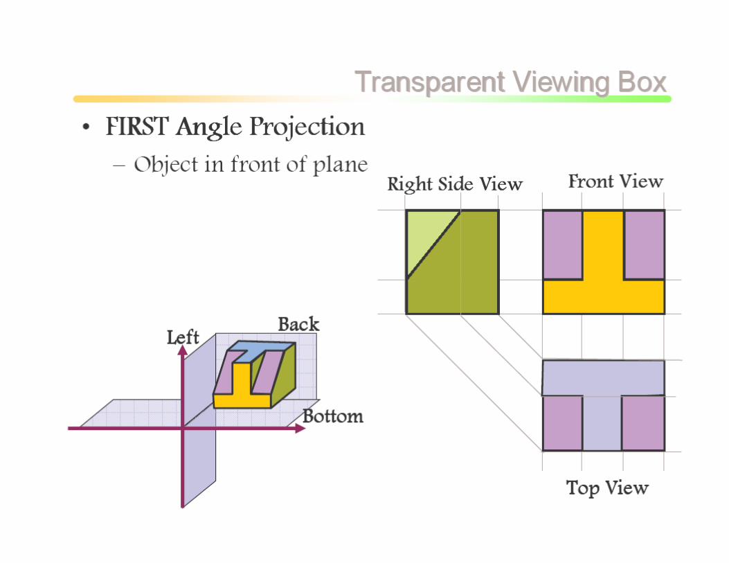
Planes & Views (first angle method)
HP IS ROTATED DOWNWARD 900
AND
BROUGHT IN THE PLANE OF VP.
PP IS ROTATED AWAY IN RIGHT SIDE 900
AND
BROUGHT IN THE PLANE OF VP.
X
Y
X Y
VP
HP
PP
FV
ACTUAL PATTERN OF PLANES & VIEWS
OF ORTHOGRAPHIC PROJECTIONS
DRAWN IN
FIRST ANGLE METHOD OF PROJECTIONS
LSV
TV

FOR T.V.First angle projection
IN THIS METHOD,
THE OBJECT IS ASSUMED TO BE
SITUATED IN FIRST QUADRANT
MEANS
ABOVE HP & INFRONT OF VP.
OBJECT IS INBETWEEN
OBSERVER & PLANE.
PP
ACTUAL PATTERN OF
PLANES & VIEWS
IN
FIRST ANGLE METHOD
OF PROJECTIONS
X Y
VP
HP
PP
FV LSV
TV

FOR T.V.
IN THIS METHOD,
THE OBJECT IS ASSUMED TO BE
SITUATED IN THIRD QUADRANT
( BELOW HP & BEHIND OF VP. )
PLANES BEING TRANSPERENT
AND INBETWEEN
OBSERVER & OBJECT.
THIRD ANGLE
PROJECTION
ACTUAL PATTERN OF
PLANES & VIEWS
OF
THIRD ANGLE PROJECTIONS
X Y
TV
LSV FV

Orthographic projections- points, lines, planes, and solids
• To draw projections of any object, one must have the following information
– Object (with it’s description, well defined)
– Observer (always observing perpendicular to respective reference plane)reference plane)
– location of object (means it’s position with reference to HP & VP)
• Terms ‘above’ & ‘below’ with respective to HP and terms ‘infront’ & ‘behind’ with respective to VP form 4 quadrants.
• Objects can be placed in any one of these 4 quadrants
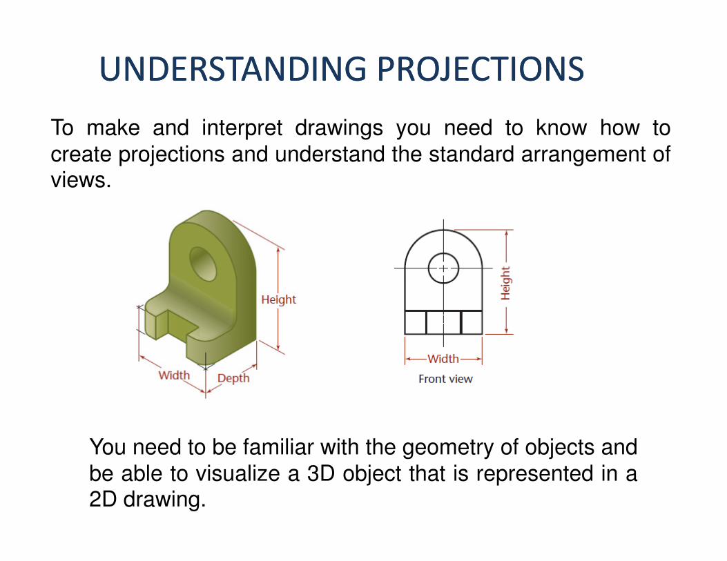
UNDERSTANDING PROJECTIONSUNDERSTANDING PROJECTIONS
To make and interpret drawings you need to know how to
create projections and understand the standard arrangement ofviews.
You need to be familiar with the geometry of objects and
be able to visualize a 3D object that is represented in a2D drawing.
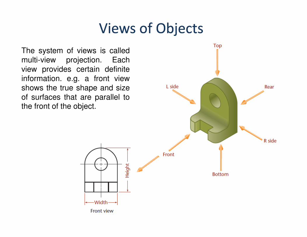
Views of ObjectsViews of Objects
The system of views is called
multi-view projection. Each
view provides certain definite
information. e.g. a front view
shows the true shape and size
of surfaces that are parallel tothe front of the object.

Principal DimensionsPrincipal Dimensions
The three principal dimensions of an object are width, height, and depth.
The front view shows only the height and
width of the object and not the depth.
In fact, any principal view of a 3D object
shows only two of the threeshows only two of the three
principal dimensions; the third is found
in an adjacent view.
Height is shown in the rear, left-side,
front, and right-side views.
Width is shown in the rear, top, front, and
bottom views.
Depth is shown in the left-side, top, right-side, and bottom views.

Envision the object in a Glass BoxEnvision the object in a Glass BoxTo understand the standard arrangement of views on the sheet of paper

To draw the views on a sheet of paper, imagine thesix planes of the glass box being unfolded to lie flat.
Note the six standard
views (front, rear, top,
bottom, right side, leftside).

The Glass Box UnfoldedThe Glass Box UnfoldedLines extend around the glass box from one view to another on the planes of
projection. These are the projectors from a point in one view to the same point inanother view.

The Orthographic ProjectionThe Orthographic Projection
The front, top, and right-side views of the object shown now without the folding lines.

Necessary ViewsNecessary Views
The top, front, and right-side views, arranged
together, are called the three regular viewsbecause they are the views most frequently used.
A drawing should contain only the views needed to clearly and completely describe the object.completely describe the object.

View Selection
Select the most descriptive views
Use minimum number of views to
describe the object
Select the most descriptive views


How to project Side Views?
• Projecting across meter line
• Projecting through arcs
• Projecting through 45 degree projectors

Projecting across meter line
X1
FVLHSV
45oX Y
Y1
Meter line
TV
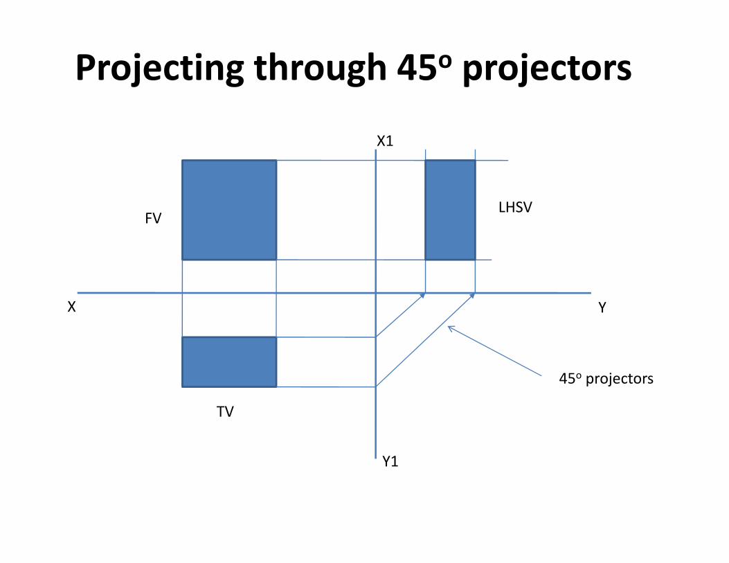
Projecting through 45o projectors
X1
FVLHSV
X Y
Y1
45o projectors
TV
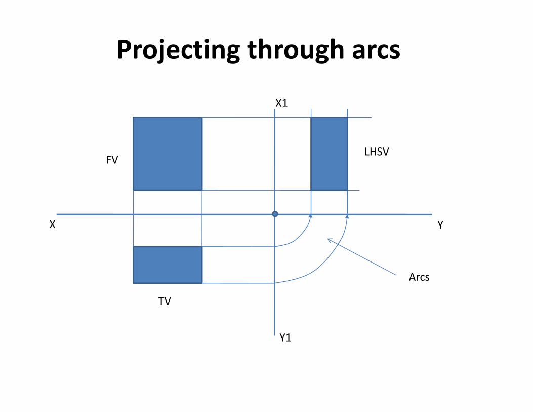
Projecting through arcs
X1
FVLHSV
X Y
Y1
Arcs
TV


Top viewThree basic views (FV, TV, SV) will provide
complete information about the real object
Top ViewTop View

VIEWS OF SURFACESVIEWS OF SURFACES
The three orientations that a plane surface can have to
the plane of projection are normal, inclined, andoblique.
A plane surface that is
perpendicular to a plane of
projection appears onedge as a straight line

Standard Views of Primitive Solids
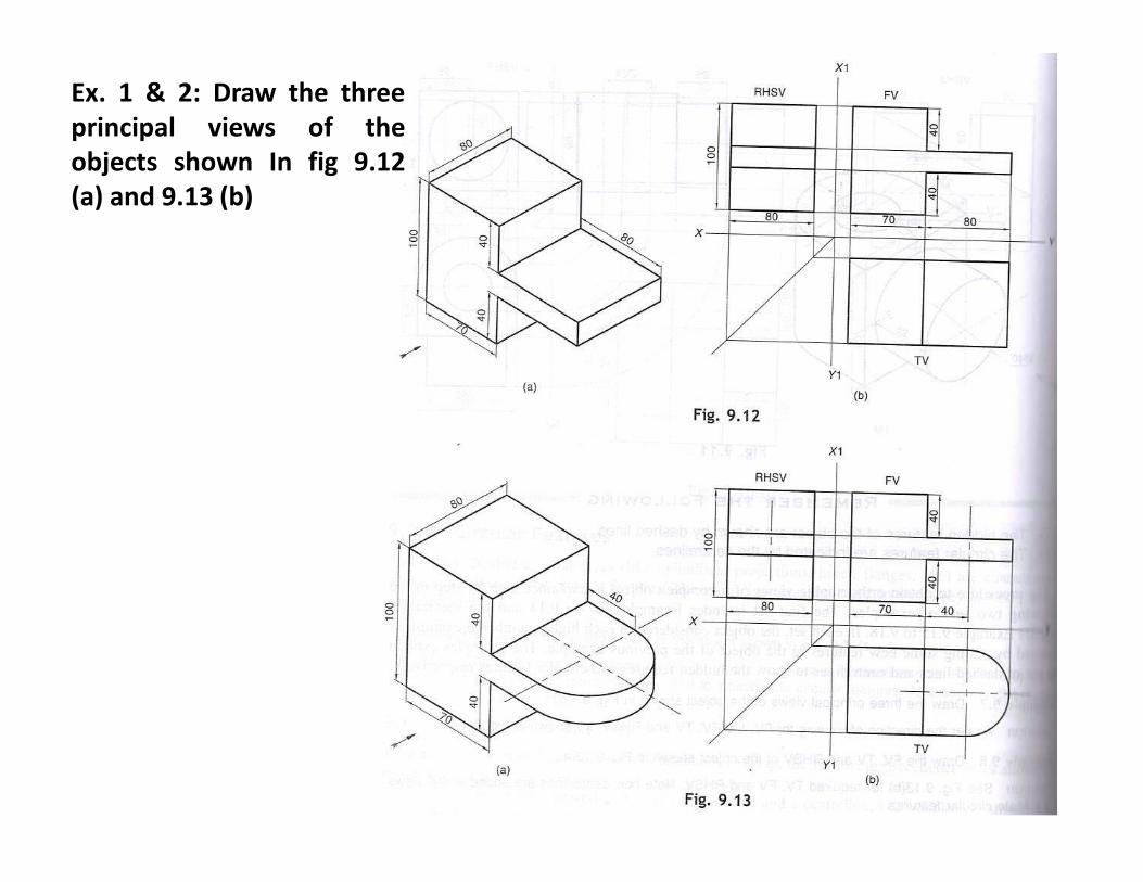
Ex. 1 & 2: Draw the three
principal views of the
objects shown In fig 9.12
(a) and 9.13 (b)
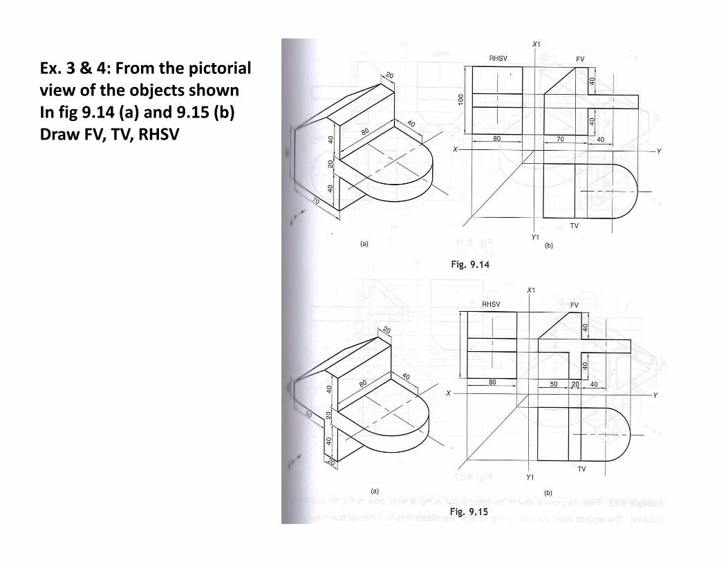
Ex. 3 & 4: From the pictorial
view of the objects shown
In fig 9.14 (a) and 9.15 (b)
Draw FV, TV, RHSV


