
INSTRUCTIONAL MATERIALSText: pages 241–260
Test Your Knowledge Questions, pages 259–260
Workbook: pages 77–84Instructor’s Resource: pages 191–206
Guide for Lesson PlanningResearch and Development IdeasReproducible Masters:
14-1 Angle Measurement andConversion
14-2 Tapers (basic information)14-3 Calculating Tailstock Setover
(taper per inch given)14-4 Calculating Tailstock Setover
(taper per foot given)14-5 Calculating Tailstock Setover
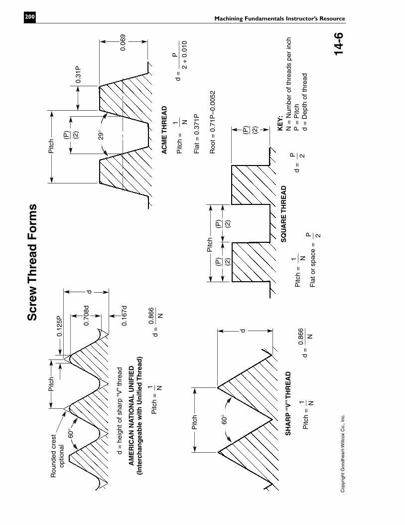
(all taper dimensions given)14-6 Screw Thread Forms
(formulas included)14-7 Screw Thread Lead and Pitch14-8 Cutting Action of Threading Tools14-9 Three-Wire Method of Measuring
Threads14-10 Test Your Knowledge Questions
Color Transparencies (Binder/CD only)
GUIDE FOR LESSON PLANNINGThis chapter can be divided into two seg-
ments. Part I should cover cutting tapers on thelathe and Part II should cover cutting screwthreads on the lathe. Copy and distributeReproducible Masters 14-1 and 14-2.
Part I—Cutting Tapers on the LatheSet up lathes for demonstration purposes.
Demonstrate the various ways tapers can be cuton a lathe.
Have students read and study pages 241–250.Review the assignment using ReproducibleMasters 14-3, 14-4, and 14-5 as overhead trans-parencies and/or handouts. (Answers are locatedon page 193 of this Instructor’s Resource.) Discussthe following:
• The advantages and disadvantages of thevarious methods used to cut tapers on alathe.
• How to calculate tailstock setover.• Methods used to setover the tailstock.• Types of taper attachments and how to set
them.• How to measure tapers.
Chapter 14
Cutting Tapers andScrew Threads on
the Lathe
LEARNING OBJECTIVESAfter studying this chapter, students will be able to:� Describe how a taper is turned on a lathe.� Calculate tailstock setover for turning a taper.� Safely set up and operate a lathe for taper turning.� Describe the various forms of screw threads.� Cut screw threads on a lathe.
191

Emphasize the safety precautions that mustbe observed when cutting tapers.
Part II—Cutting Screw Threads on the LathePrepare a lathe to cut threads. Explain and
demonstrate procedures for cutting threads.Have students read and study pages
250–259. Review the assignment after demon-strating how to set up a lathe and cut threads.Discuss the following:
• Major uses of the screw thread.• Screw thread forms. Use Reproducible
Masters 14-6 and 14-7.• Review thread nomenclature. Use Repro-
ducible Master 6-7.• Setting up a lathe to cut 60° threads.• Threading tool cutting action. Use Repro-
ducible Master 14-8.• How to use the thread dial.• The three-wire method for measuring
threads. Use Reproducible Master 14-9.• How to cut Acme threads.• How to cut internal threads.• Why cutting fluid should be used.Emphasize safety precautions to be observed
when cutting threads on a lathe. Briefly reviewthe demonstrations. Provide students with theopportunity to ask questions.
Technical TermsReview the terms introduced in the chapter.
New terms can be assigned as a quiz, home-work, or extra credit. The following list is alsogiven at the beginning of the chapter.
external threadsinternal threadsmajor diameterminor diameter offset tailstock methodpitch diameter setovertaper attachmentthread cutting stopthree-wire method of measuring threads
Review QuestionsAssign Test Your Knowledge questions. Copy
and distribute Reproducible Master 14-10 orhave students use the questions on pages259–260 in the text and write their answers on aseparate sheet of paper.
Workbook AssignmentAssign Chapter 14 of the Machining Funda-
mentals Workbook.
Research and DevelopmentDiscuss the following topics in class or have
students complete projects on their own.1. Make a display board showing large scale
models of Sharp V, square, and Acme screwthreads.
2. Write a paper on how the first screw threadswere made. If possible, include illustrations.
3. Demonstrate to the class the proper tech-nique of machining screw threads. Illustratehow the tool can be repositioned after beingresharpened and how to use the 3-wiremethod of measuring threads.
TEST YOUR KNOWLEDGEANSWERS, Pages 259–2601. Compound, offset tailstock, taper attach-
ment, tool bit, and reamer. Evaluate list ofadvantages and disadvantages individually.Refer to Figure 14-3.
2. When it increases or decreases in diameterat a uniform rate.
3. A. 0.250″B. 0.563″C. 15.7 mm
4. Making adjustments, assembling parts, trans-mitting motion, applying pressure, andmaking measurements.
5. d. Cut on outside surface of piece.6. f. Cut on inside surface of piece.7. b. Largest diameter of thread.8. a. Smallest diameter of thread.9. e. Diameter of imaginary cylinder that
would pass through threads at suchpoints as to make width of thread andwidth of space at these points equal.
10. c. Distance from one point on a thread to acorresponding point on next thread.
11. g. Distance a nut will travel in one completerevolution of screw.
12. d. All of the above.13. center gage, fish tail14. thread dial15. 29°16. a. M = 0.520″
Machining Fundamentals Instructor’s Resource192
b. M = 0.270″c. M = 0.415″d. M = 0.509″
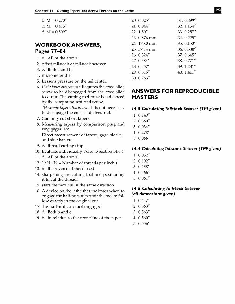
WORKBOOK ANSWERS,Pages 77–841. e. All of the above.2. offset tailstock or tailstock setover3. c. Both a and b.4. micrometer dial5. Lessens pressure on the tail center.6. Plain taper attachment. Requires the cross-slide
screw to be disengaged from the cross-slidefeed nut. The cutting tool must be advancedby the compound rest feed screw.Telescopic taper attachment. It is not necessaryto disengage the cross-slide feed nut.
7. Can only cut short tapers.8. Measuring tapers by comparison plug and
ring gages, etc.Direct measurement of tapers, gage blocks,and sine bar, etc.
9. c. thread cutting stop10. Evaluate individually. Refer to Section 14.6.4.11. d. All of the above.12. 1/N (N = Number of threads per inch.)13. b. the reverse of those used14. sharpening the cutting tool and positioning
it to cut the threads15. start the next cut in the same direction16. A device on the lathe that indicates when to
engage the half-nuts to permit the tool to fol-low exactly in the original cut.
17. the half-nuts are not engaged18. d. Both b and c.19. b. in relation to the centerline of the taper
20. 0.025″ 31. 0.899″21. 0.044″ 32. 1.154″22. 1.50″ 33. 0.257″23. 0.876 mm 34. 0.225″24. 175.0 mm 35. 0.153″25. 57.14 mm 36. 0.580″26. 0.324″ 37. 0.645″27. 0.384″ 38. 0.771″28. 0.457″ 39. 1.281″29. 0.515″ 40. 1.411″30. 0.763″
ANSWERS FOR REPRODUCIBLEMASTERS
14-3 Calculating Tailstock Setover (TPI given)1. 0.149″2. 0.380″3. 0.034″4. 0.278″5. 0.066″
14-4 Calculating Tailstock Setover (TPF given)1. 0.032″2. 0.102″3. 0.158″4. 0.166″5. 0.061″
14-5 Calculating Tailstock Setover (all dimensions given)1. 0.417″2. 0.563″3. 0.563″4. 0.560″5. 0.556″
Chapter 14 Cutting Tapers and Screw Threads on the Lathe 193

Machining Fundamentals Instructor’s Resource194

Chapter 14 Cutting Tapers and Screw Threads on the Lathe 195
Copyright Goodheart-Willcox Co., Inc. 14-1
Angle Measurement and Conversion
Angle measured from thecenterline of the workpiece
Measurement of the included angle
1/16 0° 17′ 53″ 0° 8′ 57″1/8 0° 35′ 47″ 0° 17′ 54″3/16 0° 53′ 44″ 0° 26′ 52″1/4 1° 11′ 38″ 0° 35′ 49″5/16 1° 29′ 31″ 0° 44′ 46″3/8 1° 47′ 25″ 0° 53′ 42″7/16 2° 5′ 18″ 1° 2′ 39″1/2 2° 23′ 12″ 1° 11′ 36″9/16 2° 41′ 7″ 1° 20′ 34″5/8 2° 58′ 3″ 1° 29′ 31″
11/16 3° 16′ 56″ 1° 38′ 28″3/4 3° 34′ 48″ 1° 47′ 24″
13/16 3° 52′ 42″ 1° 56′ 21″7/8 4° 10′ 32″ 2° 5′ 16″
15/16 4° 28′ 26″ 2° 14′ 13″1 4° 46′ 19″ 2° 23′ 10″
Taper perfoot
Includedangle
Angle withcenterline
Taper per Foot withCorresponding Angles
Table can be used to convert taper per foot into correspondingangles for adjustment of the compound rest.
30°
60°

Machining Fundamentals Instructor’s Resource196
Cop
yrig
ht G
oodh
eart
-Will
cox
Co.
, In
c.14
-2
Tap
ers
D =
dia
met
er a
t la
rge
end
of t
aper
;d =
dia
met
er a
t sm
all
end
of t
aper
; l=
leng
th o
f ta
per;
L =
tot
al le
ngth
of
piec
e.
C
of la
the
Tails
tock
seto
ver
L
Leng
th o
f w
ork
caus
es t
aper
to
vary
eve
n th
ough
tai
lsto
ckof
fset
rem
ains
the
sam
e.

The tailstock offset must be calculated for each job because the work length plays animportant role in the calculation. Information needed: TPI = Taper per inch, L = Total lengthof work.
Formula: When taper per inch is known, Offset =
1. What will be the setover for the following job? Show your work.
TPI = 0.035″ L = 8.500″
2. What will be the setover for the following job? Show your work.
TPI = 0.062″ L = 12.25″
3. What will be the setover for the following job? Show your work.
TPI = 0.009″ L = 7.625″
4. What will be the setover for the following job? Show your work.
TPI = 0.055″ L = 10.125″
5. What will be the setover for the following job? Show your work.
TPI = 0.025″ L = 5.250″
L × TPI2
Chapter 14 Cutting Tapers and Screw Threads on the Lathe 197
Copyright Goodheart-Willcox Co., Inc. 14-3
Calculating Tailstock Setover

The tailstock offset must be calculated for each job because the work length plays animportant role in the calculation. When the taper per foot (TPF) is known, it must first beconverted to taper per inch (TPI). The following formula takes this into account.
Formula: When taper per foot is known, Offset =
1. What will be the setover for the following job? Show your work.
TPF = 0.123″ L = 6.330″
2. What will be the setover for the following job? Show your work.
TPF = 0.250″ L = 9.750″
3. What will be the setover for the following job? Show your work.
TPF = 0.375″ L = 10.125″
4. What will be the setover for the following job? Show your work.
TPF = 0.312″ L = 12.75″
5. What will be the setover for the following job? Show your work.
TPF = 0.126″ L = 6.750″
L × TPF24
Machining Fundamentals Instructor’s Resource198
Copyright Goodheart-Willcox Co., Inc. 14-4
Calculating Tailstock Setover

The tailstock setover must be calculated for each job because the work length plays animportant role in the calculation. Often plans do not specify TPI, TPF, or T/mm, but doprovide pertinent information. If inch dimensions are given in fractions, they must beconverted to decimals.
Formula: Offset =
1. What will be the setover for the following job? Show your work.
D = 2.000″ d = 1.500″ l = 6.000″ L = 10.000″
2. What will be the setover for the following job? Show your work.
D = 1.125″ d = 0.750″ l = 3.000″ L = 9.000″
3. What will be the setover for the following job? Show your work.
D = .875″ d = 0.500″ l = 4.000″ L = 12.000″
4. What will be the setover for the following job? Show your work.
D = 1.375″ d = 0.937″ l = 6.000″ L = 15.00″
5. What will be the setover for the following job? Show your work.
D = 2 1/2″ d = 1 15/16″ l = 6 1/8″ L = 12 1/8″
L × (D – d)2 × l
Chapter 14 Cutting Tapers and Screw Threads on the Lathe 199
Copyright Goodheart-Willcox Co., Inc. 14-5
Calculating Tailstock Setover
Machining Fundamentals Instructor’s Resource200
Cop
yrig
ht G
oodh
eart
-Will
cox
Co.
, In
c.14
-6
Scr
ew T
hre
ad F
orm
s
d =
hei
ght
of s
harp
“V
”th
read
Rou
nded
cre
stop
tiona
l
Pitc
h
d0.
708d
0.12
5P
AM
ER
ICA
N N
AT
ION
AL
UN
IFIE
D(I
nte
rch
ang
eab
le w
ith
Un
ifie
d T
hre
ad)
0.16
7d
Pitc
h
SH
AR
P “
V”
TH
RE
AD
d
0.06
9
AC
ME
TH
RE
AD
N =
Num
ber
of t
hrea
ds p
er in
chP
= P
itch
d =
Dep
th o
f th
read
Pitc
h
0.31
P
Pitc
h SQ
UA
RE
TH
RE
AD
KE
Y:
29°
60°
60°
0.86
6N
d =
1 NP
itch
=
0.86
6N
d =
1 NP
itch
=
11 NP
itch
=
P 2F
lat
or s
pace
=
P 2d
=
(P)
(2)
(P)
(2)
(P)
(2)
(P)
(2)
11 NP
itch
=
Fla
t =
0.3
71P
Roo
t =
0.7
1P–0
.005
2
P2
+ 0
.010
d =

Chapter 14 Cutting Tapers and Screw Threads on the Lathe 201
Copyright Goodheart-Willcox Co., Inc. 14-7
Screw Thread Lead and Pitch
Triple Thread Screw(The lead is three times the pitch)
Double Thread Screw(The lead is twice the pitch)
Single Thread Screw(Pitch and thread are equal)

Machining Fundamentals Instructor’s Resource202
Cop
yrig
ht G
oodh
eart
-Will
cox
Co.
, In
c.14
-8
Cu
ttin
g A
ctio
n o
fT
hre
adin
g T
oo
ls
Dire
ctio
nof
feed
Dire
ctio
nof
feed
Tip
of
thre
adin
gto
ol w
ill b
reak
off
and
thre
ads
will
not
be a
ccur
ate
Whe
n th
e to
ol i
s fe
d in
at
a 29
° an
gle,
not
e th
aton
ly o
ne e
dge
is c
uttin
g an
d th
at th
e cu
tting
load
isdi
strib
uted
eve
nly
acro
ss t
he e
dge.
Whe
n fe
d st
raig
ht in
, not
e th
at b
oth
edge
s ar
e cu
tting
and
the
wea
kest
par
t of
the
too
l, th
e po
int,
is d
oing
the
hard
est
wor
k.
Usi
ng a
full-
prof
ile in
sert
tocu
t a
thre
ad.
A s
epar
ate
inse
rt i
s re
quire
d fo
r ea
chth
read
pitc
h.
Cut
ting
thre
ads
with
a p
artia
l-pr
ofile
inse
rt.T
he m
ajor
(ou
t-si
de)
diam
eter
of
the
thre
adm
ust
be
cut
to
size
be
fore
usin
g th
is t
ype
inse
rt.

Chapter 14 Cutting Tapers and Screw Threads on the Lathe 203
Copyright Goodheart-Willcox Co., Inc. 14-9
Three-Wire Method of Measuring Threads
Micrometer
Micrometer
G
MDd
P

Name: ______________________________________________Date: _______________ Score: ________
1. There are five ways of machining tapers on a lathe. List them, with their advantages and disad-vantages.
____________________________________________________________________________________
____________________________________________________________________________________
____________________________________________________________________________________
____________________________________________________________________________________
2. When is a section of material considered tapered?________________________________________
____________________________________________________________________________________
3. Machine adjustments must be calculated for each tapering job. The information given below willenable you to calculate the necessary tailstock setover for the problems given. Show your work inthe space provided.
Formulas: When taper per inch is known, Offset =
When taper per foot is known, Offset =
When dimensions of tapered section are known but TPI or TPF is not given,
Offset =
Where: TPI = Taper Per Inch TPF = Taper Per Foot
D = Diameter at large end of taper d = Diameter at small end of taper
l = Length of taper L = Total length of piece
Note: These formulas, except for the TPF formula, can be used when dimensions are in mm.
Problem A: What will the tailstock setover be for the following job?
Taper Per Inch = 0.125″ Total length of piece = 4.000″
L × TPI2
Machining Fundamentals Instructor’s Resource204
Copyright Goodheart-Willcox Co., Inc. 14-10
Cutting Tapers and Screw Threads on the Lathe
(continued)
L × TPF2
L × (D – d)2 × l
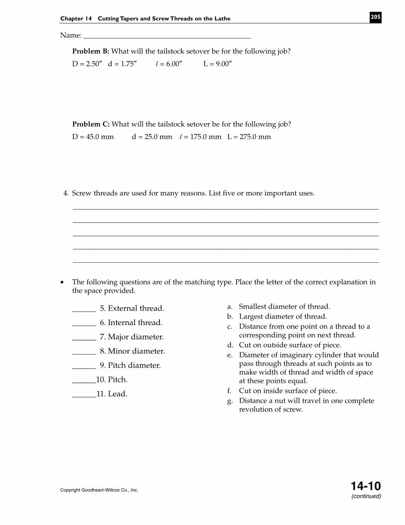
Problem B: What will the tailstock setover be for the following job?
D = 2.50″ d = 1.75″ l = 6.00″ L = 9.00″
Problem C: What will the tailstock setover be for the following job?
D = 45.0 mm d = 25.0 mm l = 175.0 mm L = 275.0 mm
4. Screw threads are used for many reasons. List five or more important uses.
____________________________________________________________________________________
____________________________________________________________________________________
____________________________________________________________________________________
____________________________________________________________________________________
____________________________________________________________________________________
• The following questions are of the matching type. Place the letter of the correct explanation inthe space provided.
______ 5. External thread.
______ 6. Internal thread.
______ 7. Major diameter.
______ 8. Minor diameter.
______ 9. Pitch diameter.
______10. Pitch.
______11. Lead.
Chapter 14 Cutting Tapers and Screw Threads on the Lathe 205
Copyright Goodheart-Willcox Co., Inc. 14-10(continued)
Name: ______________________________________________
a. Smallest diameter of thread.b. Largest diameter of thread.c. Distance from one point on a thread to a
corresponding point on next thread.d. Cut on outside surface of piece.e. Diameter of imaginary cylinder that would
pass through threads at such points as tomake width of thread and width of spaceat these points equal.
f. Cut on inside surface of piece.g. Distance a nut will travel in one complete
revolution of screw.

12. A groove is cut at the point where a thread is to terminate.It is cut to the depth of the thread and serves to:a. provide a place to stop the threading tool after it
makes a cut.b. permits a nut to be run up to the end of the thread.c. terminate the thread.d. All of the above.e. None of the above.
13. The tip of a cutting tool to cut a Sharp V thread issharpened using a _____ to check that it is the correctshape. This tool is frequently called a _____.
14. The _____ is fitted to many lathe carriages. It mesheswith the lead screw and is used to indicate when toengage the half nuts to permit the thread cutting tool tofollow exactly in the original cut.
15. The compound rest is set at _____ when cutting threadsto permit the cutting tool to shear the material betterthan if it were fed straight into the work.
16. The three-wire thread measuring formula for inch-based threads is:
M = D + 3G –
Where: G = Wire diameter D = Major diameter of thread (Convert to decimal size).
M = Measurement over the wires N = Number of threads per inch.
Problems: Calculate the correct measurement over the wires for the following threads. Use the wiresize given in the problem. Show your work in the space provided.
______ a. 1/2-20 UNF (wire size 0.032″)
______ b. 1/4-20 UNC (wire size 0.032″)
______ c. 3/8-16 UNC (wire size 0.045″)
______ d. 7/16-14 UNC (wire size 0.060″)
Machining Fundamentals Instructor’s Resource206
Name: ______________________________________________
12. ____________________________
13. ____________________________
____________________________
14. ____________________________
15. ____________________________
Copyright Goodheart-Willcox Co., Inc. 14-10
1.5155N


