Download - LC709203F-01-GEVB Test Procedure

Test Procedure for the LC709203F-01 Evaluation Board
Scope The LC709203F measures the remaining power of a 1-cell lithium-ion battery. This product uses a unique correction technology to make battery temperature and voltage measurements. With this technology high precision measurement can be made without the need for an external sense resistor. The following is a manual that describes how to use the Fuel Gauge Interactive Software.
Contents
Overview ................................................................................................................................. 3
Evaluation Kit .......................................................................................................................... 3
Connection Instructions ........................................................................................................... 5
Evaluation Procedures ............................................................................................................. 6
Graphical Analysis ................................................................................................................. 15
Smartphone Evaluation Example ........................................................................................... 18
FAQ’S..................................................................................................................................... 20
Related Documents ............................................................................................................... 20
Revision History..................................................................................................................... 20
08/20/2014 1 www.onsemi.com

1. Overview
The LC709203F is an IC that measures the remaining power of a 1-cell lithium-ion battery and displays the Relative State of Charge (RSOC). This product reduces fuel gauge errors with a unique correction technology during measurement of battery temperature and voltage. The LC709203F has the option of four possible battery profiles to select from for best precise RSOC readings. This technology has inherent high precision without the need for an external sense resistor.
2. Evaluation Kit
2.1 Evaluation Board for LC709203F Fuel Gauge
Evaluation Board Part Numbers:
1) LC709203FQH-01-GEVB for VDFN8 Package
2) LC709203FXE-01-GEVB for WLCSP9 Package
-Easy to use: Minimal Connections required
08/20/2014 2 www.onsemi.com

2.2 Fuel Gauge Interactive Software
-Supported Platforms: Windows XP and Windows 7
Fuel Gauge software can be found on the ON Semiconductor Website at onsemi.com and searching part #LC709203F.
2.3 Evaluation Board Block Diagram
08/20/2014 3 www.onsemi.com

3. Connection Instructions
3.1 Connecting of Evaluation Board
-Connect
Evaluation Board Positive Connector + →→ Battery Pack +
Evaluation Board Negative Connector - →→ Battery Pack –
Battery Pack
08/20/2014 4 www.onsemi.com

3.2 Connection to PC
-Connect USB cable to Evaluation Board
USB
LED1 and LED3 will turn on (backside) with proper connection
08/20/2014 5 www.onsemi.com

4. Evaluation Procedures
4.1 Software Start-Up
-Start program FIGICTool_ver008.exe
08/20/2014 6 www.onsemi.com

4.2 Communication Type Selection
-Select communication type: I2C
-Select desired time interval and frequency:
08/20/2014 7 www.onsemi.com

4.3 Changing IC Power Mode
-Change mode of Fuel Gauge to ‘Operational Mode’ Do the following in the Write Word Sub Communication window Input [15] in Command box
Input [0001] in Data box
Press [Write Word] to complete writing register 0x15 (Twice)
It is recommended to do this task twice, once for a ‘wake up’ and second to set Fuel Gauge in to
‘Operational Mode’.
*While powering on Fuel Gauge, IC starts up in sleep mode. It is essential to ensure IC is set to
‘Operational Mode’ for accurate measurement.
08/20/2014 8 www.onsemi.com

4.4 Impedance Path Assignment
Account for impedance from battery up too Fuel Gauge
Do the following in the Write Word Sub Communication window
Input [0B] in Command box
Input [XXXX] in Data box
Press [Write Word] to complete writing register 0x0B
* This register accounts for the impedance track from the battery to Fuel Gauge. This
impedance path can include: Protection IC’s, long leads, and internal resistance.
08/20/2014 9 www.onsemi.com

4.5 Battery Profile Assignment
Assign correct batter profile, for best accurate measurements. Do the following in the Write Word Sub Communication window
Input [12] in Command box Input [000X] in Data box
Press [Write Word] to complete writing register 0x12
The LC709203F has the option of having either battery profile 301 or 504 pre-loaded. Each battery profile has two optional battery types to select from. Selecting the correct battery profile and type is crucial for accurate results. Please review Table 1 in order to select correct battery profile and type.
Table 1: Table of Battery Profiles and Types
IC-Type Nominal/Rated
Voltage Charging Voltage Battery Type Battery Profile
LC709203F-01
3.7 V 4.2V Type 01
301 3.8V 4.35V Type 03
Any Type Re-Scaling Required
LC709203F-04
Use only for UR-18650ZY (Panasonic) Type 04
504 Use only for ICR18650-26H (Samsung) Type 05
Any Type Re-Scaling Required
08/20/2014 10 www.onsemi.com

4.6 Intialization of Battery Capacity
For best results initialize battery capacity.
Do the following in the Write Word Sub Communication window
Input [07] in Command box
Input [AA55] in Data box
Press [Write Word] to complete writing register 0x07
*This will assign the most accurate Relative State of Charge (RSOC) of the battery being
monitored
08/20/2014 11 www.onsemi.com

4.7 Thermistor Mode
The LC709203F has the option of using a thermistor for cell temperature measurements. The
following steps show how to enable the thermistor. Upon start up LC709203F has default
setting with thermistor mode disabled.
Do the follwing in Sub Communication window
Input [16] in Command box
Iinput [0001] in Data box
Press [Write Word] to enable Thermistor
08/20/2014 12 www.onsemi.com
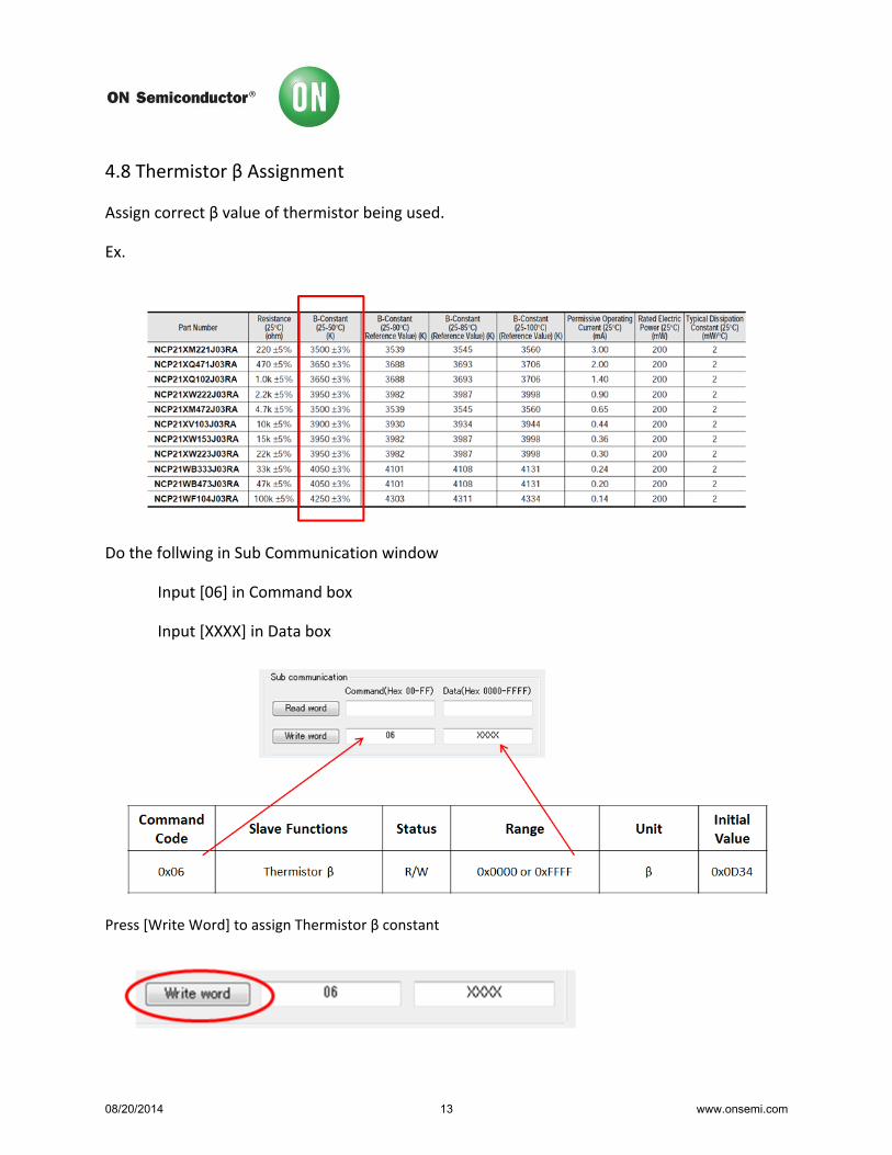
4.8 Thermistor β Assignment
Assign correct β value of thermistor being used.
Ex.
Do the follwing in Sub Communication window
Input [06] in Command box
Input [XXXX] in Data box
Press [Write Word] to assign Thermistor β constant
08/20/2014 13 www.onsemi.com

4.9 Start of Measurements
Press [Start Measure] to begin measurements
4.10 Sample Measurements
With a successful connection you will see screen as above
Voltage (mV)
Cell temperature RSOC
08/20/2014 14 www.onsemi.com

5 Graphical Analysis
The LC709203F software has the option to save all measurements via a text file. Measured data
can be converted in to excel format. Once in excel format, data can be plotted for analysis. A
graph can give a great visual to see how the LC709203F tracks voltage and RSOC over time.
5.1 Storing Measured Data
To save data to a text file, do the following:
Press [Stop measure]
Press [Store log]
Measured Data becomes a txt file
Save Fuel Gauge Data Example.txt
08/20/2014 15 www.onsemi.com
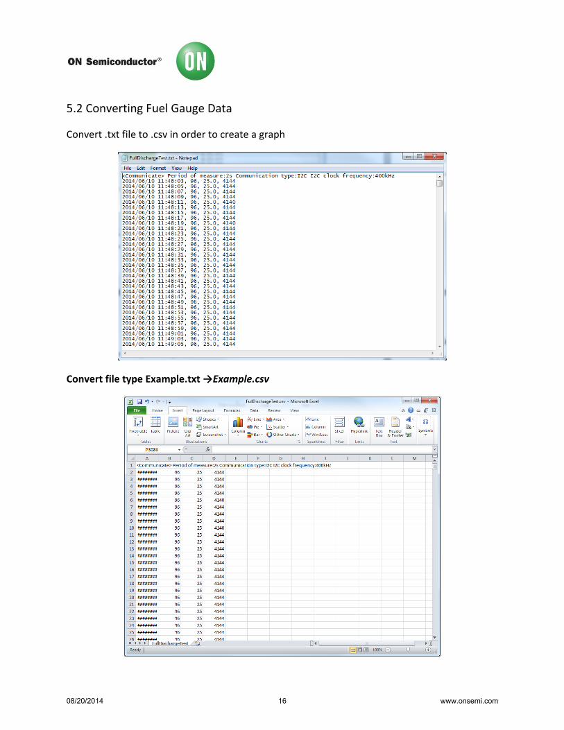
5.2 Converting Fuel Gauge Data
Convert .txt file to .csv in order to create a graph
Convert file type Example.txt →Example.csv
08/20/2014 16 www.onsemi.com

5.3 Create a Graph
Graph Displays:
1) RSOC vs. Time
2) Voltage vs. Time
Graph gives a visual representation of how the LC709203F tracks battery voltage while
discharging.
A separate graph to model a charging pattern can be obtained by taking measurements while
charging a battery pack using the LC709203F software.
08/20/2014 17 www.onsemi.com

6. Smartphone Evaluation Example
The LC709203F Evaluation board can be used to analyze applications. Here is an example of an
analysis of a smartphone undergoing charging and discharging conditions.
6.1 Block Diagram
08/20/2014 18 www.onsemi.com

6.2 Testing Results #1
6.3 Testing Results #2
08/20/2014 19 www.onsemi.com

Test Results
Test 1: This test shows the use of a smartphone over an 8 hour window. During this 8 hour
window the smartphone went through a charge/discharge state. During charge state the phone
was being charged via charger and discharged by using features on smartphone. This graph
displays how the LC709203F tracks the voltage level and displays a RSOC value.
Test 2: Smartphone starts off 100% charged then discharges due to recording a movie. The
battery is then removed, charged, and then put back in to smartphone. The LC709203F tracks
the voltage level and displays a RSOC value.
08/20/2014 20 www.onsemi.com

7. FAQ’s
Q. How do I know what battery profile to use?
A. Battery characteristics are listed on Table 2. If battery you wish to use is not listed on Table 2, please contact ON Semiconductor.
Q. Why does my Fuel Gauge continue to display same voltage value?
A. Please ensure Fuel Gauge is not in ‘Sleep’ mode. Following Fuel Gauge Initialization Flow Chart will ensure it reads proper values.
Q. What if I order Fuel Gauge with battery profile 301 but need battery profile 504 instead?
A. Alternative battery profile can be made available, please contact ON Semiconductor for more information.
Q. How do I load a new battery profile to LC709203F?
A. After receiving new battery profile from ON Semiconductor please use software to Flash the new profile on to Fuel Gauge.
Q. I tried loading a new battery profile but I am receiving a Flash Write error?
A. Please insure that IC is not in ‘Sleep mode, please follow Fuel Gauge initiation to place IC in ‘Operational’ mode.
8. Related Documents
Supporting information such as: Datasheets, Application Notes, Evaluation Board Documents and Software are available for the LC709203F.To obtain the most updated documentation please visit the ON Semiconductor Web site at www.onsemi.com and search part number: LC709203F.
1) LC709203F, Battery Monitor IC for 1-Cell Lithium-ion Li+ Data Sheet (Data Sheet) 2) LC709203F, Application Note (App. Note) 3) LC709203F, Evaluation Board Documents (Evaluation Board Docs) 4) LC709203F, Software FGICTool (Software)
08/20/2014 21 www.onsemi.com

9. Revision History
Version Date Details
1.0 08/20/2014 Initial Release
08/20/2014 22 www.onsemi.com


