
Ko
mG
uid
e
w w w . k o m e t g r o u p . c o m
ZAHRANCO, ENGINEERING TRADE15, Ali Amer Str. · 6th SectorNasr City · Cairo, EgyptTel. ++20-2-2 75 43 46Fax ++20-2-2 75 41 83Telex 2 10 57 YAZCO UN
VORTEX S.R.L.Pedro Morán 858, Lomas del MiradorBuenos Aires, ArgentinaTel. ++54-(11) 46 53 01 25Fax ++54-(11) 44 88 60 [email protected]
Rosler International PTY Ltd.P.O. BOX 696, 12 The NookBayswater, Vic. 3153, AustraliaTel. ++61-3-97 38 08 89Fax ++61-3-97 38 08 87
Komet do Brasil Ltda.Rua Brasileira, 43907043-010 Guarulhos - São PauloBRASILTel. +55(0)11.6423-5502Fax +55(0)[email protected]
KOMET GROUP Precision Tools (Taicang) Co.,Ltd.(Headquarter Asia Pacific)No. 5 Schaeffler RoadTaicang, Jiangsu Province, 215400ChinaTel. +86(0)512.535757-58Fax +86(0)[email protected]
KOMET Precision Tools India Pvt., Ltd.121/B, Bommasandra Industrial AreaBANGALORE - 560 099 INDIATel. ++91-80-2-7 83 48 21Fax ++91-80-2-7 83 44 [email protected]
PT Somagede Perkasa Kompleks Griya Inti SentosaJalan Griya Agung No: 3Sunter Agung - Jakarta 14350IndonesiaTel. ++62-21-6 41 07 30Fax ++62-21-6 40 15 [email protected]
SHIVEH TOLID Co. LTD.# 270, West Dr. Fatemi Ave.Post Code : 14186Tehran – IranTel. ++98 21 6 691 7 691Fax ++98 21 6 691 7 [email protected]
ARNOLD TRADING Co., Ltd.P.O.B. 201806 Hamachtesh St.Ind. Area, Holon 58810, IsraelTel. ++9 72-3-5 58 13 13Fax ++9 72-3-5 58 13 17
KOMET GROUP KKTomei Grand BLD2-30 Issha Meito465-0093 Nagoya, JapanTel. +81(52)7092311Fax +81(52)[email protected]
KOMET of America, Inc.2050 Mitchell Blvd.Schaumburg, IL 60193-4544, USATel. ++1-8 47-9 23 84 00++1-8 47-9 23 84 80Fax ++1-8 00-8 65/66 [email protected]
Office KOMET South Korea1st floor, 98-45, Sillim 2-dong,Gwanak-gu, Seoul, Korea, 151-855Tel. ++82-2-874-2926Fax [email protected]
GP System (Malaysia) Sdn Bhd19-1, Jalan Kenari 7Bandar Puchong Jaya 47100 Puchong, Selangor, MalaysiaTel. ++60-3-807 59160Fax ++60-3-807 [email protected]
KOMET de Mexico, S. de R.L. de C.V.Acceso „A“, No. 110Parque Industrial Jurica, 76120, Queretaro, Qro. MexicoTel. ++52 442 2-18-25-44Fax ++52 442 [email protected]
Coulson Carbide LimitedDouble J Centre, 24 Gum Road,Henderson Valley, HendersonP.O.Box 21-228, HendersonAuckland, New ZealandTel. ++64-9-8 38 50 61Fax ++64-9-8 37 62 86
GP System (Singapore) Pte. Ltd.No. 51, Bukit Batok Crescent#04-04/05 Unity CentreSingapore 658077Tel. ++65-68 61 26 63Fax ++65-68 61 35 [email protected]
MULTITRADE DISTRIBUTORSP.O. Box 3511, Kempton Park, 1620South AfricaTel. ++27-11-453-8034 Fax ++27-11-453-9696
Hung Chih Ltd., Co.No. 37, Chung Cheng RoadTainan, Taiwan, R.O.C.Tel. ++8 86-6-2 25 22 16Fax ++8 86-6-2 20 59 [email protected]
GP System (Thailand) Co.,Ltd77 Soi Charansanitwong 49/1Bangbumru, BangpladBangkok 10700ThailandTel. ++66-2-4 35 68 20Fax ++66-2-4 35 68 [email protected]
Outside Europe
Egypt
Argentina
Australia
Brazil
China
India
Indonesia
Iran
Israel
Japan
USA · Canada
Korea
Malaysia
Mexico
New Zealand
Singapore
South Africa
Taiwan
Thailand
Precision has a name
Precision and qualitiy do not allow any com-
promises in universal cutting operations.
KOMET GROUP is a leading system supplier
going global for precision tools and offers in-
dividual problem solvings and innovative top
engineering. This guarantees consistent quali-
ty and economic efficiency.
Precision tools for drilling into the solid, bo-
ring, fine boring, reaming, milling, turning,
threading and for special applications - this is
represented by the name of KOMET GROUP.
Technical Manual
Drilling ✔Threading ✔
Reaming ✔
Tech
nica
l Man
ual
KOMET Precision Tools GmbH & Co. KGZeppelinstraße 3 · 74351 BesigheimGERMANYTel. +49(0)7143.373-0Fax +49(0)7143.373-233E-mail [email protected]
JEL Precision Tools GmbH & Co. KGRuppmannstraße 32 · 70565 Stuttgart / VaihingenGERMANYTel. +49(0)711.78891-0Fax +49(0)711.78891-11E-mail [email protected]
Dihart AG Precision ToolsIndustriestrasse 2 · 4657 DullikenSWITZERLANDTel. +41(0)62.28542-00Fax +41(0)62.28542-99E-mail [email protected]
399 01 099 00-3T-07/07 Printed in Germany© 2007 KOMET Precision Tools GmbH & Co. KG© 2007 JEL Precision Tools GmbH & Co. KG© 2007 Diahrt AG Precision ToolsWe reserve the right to make modifications.

�
w w w . k o m e t g r o u p . c o m
THE GROUP OF SOLUTIONS
Index Page
Generalinformation 4–�7Formulae,surfaces,surfacequality,etc.FormandpositiontolerancesInternationalMaterialClassification
KOMETDrilling 1.�8–1.53Roughing 1.54–1.75Fineboring 1.76–1.97
JELThreading 2.2–2.35
DihartReaming 3.2–3.28

P1.
0
# 500
2.0 500-900
2.1 < 500
3.0 > 900
4.0 > 900
4.1
S5.
0 250
5.1 400
M6.
0
# 600
6.1 < 900
7.0 > 900
K8.
0 180
8.1 250
9.0
# 600 130
9.1 230
10.0 > 600 250
10.1 200
10.2 300
N12
.0 90
12.1 100
13.0 60
13.1 75
14.0 100
H 15.0 1400
16.0 1800
P1.
1
# 400 # 120
1.2
# 700 # 200
1.3
# 850 # 250
1.4
# 850 # 250
1.5 > 850, # 1200 > 250, # 350
1.6 > 1200 >350
H 1.7
# 1400 # 400
1.8
# 2200 # 600
M2.
1
# 850 # 250
2.2
# 850 # 250
2.3
# 1000 # 300
K3.
1
# 500 # 150
3.2 > 500, # 1000 > 150, # 300
3.3
# 700 # 200
3.4 > 700, # 1000 > 200, # 300
3.5
# 700 # 200
3.6 > 700, <1000 > 200, # 300
S4.
1
# 700 # 200
4.2
# 900 # 270
4.3 > 900, # 1250 > 270, # 300
5.1
# 500 # 150
5.2
# 900 < 270
5.3 > 900, # 1200 > 270, # 350
N6.
1
# 350 # 100
6.2
# 700 # 200
6.3
# 700 # 200
6.4
# 500 # 470
7.1
# 350 # 100
7.2
# 600 # 180
7.3
# 600 # 180
7.4
# 600 < 180
7.5
# 600 # 180
8.1
8.2
8.3
Mat
eria
l gro
up
Stre
ngth
Rm
[N/m
m2 ]
Hard
ness
HB
Material
magnetic soft iron
structural, case hardened steel
carbon steel
alloy steel
alloy / heat treated steel
alloy / heat treated steel
hardened steel to 45 HRC
hardened steel to 58 HRC
stainless steel, sulphuretted
stainless steel, austentic
stainless steel, ferritic, ferritic & austentic, martensitic
grey cast iron
grey cast iron, heat treated
spheroidal graphite cast iron
spheroidal graphite cast iron, heat treated
malleable iron
malleable iron, heat treated
pure titanium
titanium alloys
titanium alloys
pure nickel
nickel alloys, heat resistant
nickel alloys, high heat resistant
non-alloy copper
short chip, brass, bronze, red brass
long chip brass
Cu-Al-Fe-alloy (Ampco)
Al, Mg, non-alloy
Al wrought alloy, breaking strain (A5) < 14%
Al wrought alloy, breaking strain (A5) $ 14%
Al cast alloy, Si < 10%
Al cast alloy, Si $ 10%
Thermoplastics
Thermosetting plastics
Fibre reinforced plastics
Selecting the material – ThreadingSelecting the material – Drilling / ReamingM
ater
ial g
roup
Stre
ngth
Rm
[N/m
m2 ]
Hard
ness
HB
MaterialMaterial example material code/DIN
non-alloy steels St37-2/1.0037; 9SMn28/1.0715; St44-2/1.0044
non-alloy / low alloy steels St52-2/1.0050; C55/1.0525; 16MnCr5/1.7131
lead alloys 9SMnPb28/1.0718
non alloy / low alloy steels: heat resistant structural, heat treated, nitride and tools steels 42CrMo4/1.7225; CK60/1.1221
high alloy steels X6CrMo4/1.2341; X165CrMoV12/1.2601
HSS
special alloys Inconel 718/2.4668; Nimonic 80A/2.4631
titanium, titanium alloys TiAl5Sn2/3.7114
stainless steels X2CrNi189/1.4306; X5CrNiMo1810/1.4401
stainless steels X8CrNb17/1.4511; X10CrNiMoTi1810/1.4571
stainless / fireproof steels X10CrAl7/1.4713; X8CrS-38-18/1.4862
gray cast iron GG-25/0.6025; GG-35/0.6035
alloy gray cast iron GG-NiCr202/0.6660
spheroidal graphite cast iron (ferritic) GGG-40/0.7040
spheroidal graphite cast iron (ferritic/perlitic)GGG-50/0.7050; GGG-55/0.7055; GTW-55/0.8055spheroidal graphite cast iron (perlitic), malleable iron GGG-60/0.7060; GTS-65/0.8165
alloyed spheroidal graphite cast iron GGG-NiCr20-2/0.7661
vermicular cast iron GGV Ti<0,2; GGV Ti>0,2
copper alloy, brass, lead-alloy bronze, lead bronze (good cut) CuZn36Pb3/2.1182; G-CuPb15Sn/2.1182
copper alloy, brass, bronze (average cut) CuZn40Al1/2.0550; E-Cu57/2.0060
wrought aluminium alloys AlMg1/3.3315; AlMnCu/3.0517
cast aluminium alloy (Si-content <10%), magnesium alloyG-AlMg5/3.3561; G-AlSi9Mg/3.2373
cast aluminium alloy (Si-content >10%) G-AlSi10Mg/3.2381
hardened steels (< 45 HRC)
hardened steels (> 45 HRC)
NotesPatentesABS® EP 0 547 049 and other patentsKUB Quatron® patent applicationsKUB Trigon® EP 883 455 and other patentsKUB Duon® EP 1 296 793 and other patents and patent applicationsKUB Centron® EP 0 586 423 and other patent applications KUB® V464 EP 0 586 423 and other patentsTwinKom® G01 EP 0 472 562, EP 0 472 563 and other patentsUniTurn® EP 0 973 625 and other patents and patent applicationsMicroKom® M03Speed EP 0 484 407 and other patentsMicroKom® M040 EP 0 491 724 and other patentsReamax® EP 1 259 350, EP 1 474 258

P1.
0
# 500
2.0 500-900
2.1 < 500
3.0 > 900
4.0 > 900
4.1
S5.
0 250
5.1 400
M6.
0
# 600
6.1 < 900
7.0 > 900
K8.
0 180
8.1 250
9.0
# 600 130
9.1 230
10.0 > 600 250
10.1 200
10.2 300
N12
.0 90
12.1 100
13.0 60
13.1 75
14.0 100
H 15.0 1400
16.0 1800
P1.
1
# 400 # 120
1.2
# 700 # 200
1.3
# 850 # 250
1.4
# 850 # 250
1.5 > 850, # 1200 > 250, # 350
1.6 > 1200 >350
H 1.7
# 1400 # 400
1.8
# 2200 # 600
M2.
1
# 850 # 250
2.2
# 850 # 250
2.3
# 1000 # 300
K3.
1
# 500 # 150
3.2 > 500, # 1000 > 150, # 300
3.3
# 700 # 200
3.4 > 700, # 1000 > 200, # 300
3.5
# 700 # 200
3.6 > 700, <1000 > 200, # 300
S4.
1
# 700 # 200
4.2
# 900 # 270
4.3 > 900, # 1250 > 270, # 300
5.1
# 500 # 150
5.2
# 900 < 270
5.3 > 900, # 1200 > 270, # 350
N6.
1
# 350 # 100
6.2
# 700 # 200
6.3
# 700 # 200
6.4
# 500 # 470
7.1
# 350 # 100
7.2
# 600 # 180
7.3
# 600 # 180
7.4
# 600 < 180
7.5
# 600 # 180
8.1
8.2
8.3
Mat
eria
l gro
up
Stre
ngth
Rm
[N/m
m2 ]
Hard
ness
HB
Material
magnetic soft iron
structural, case hardened steel
carbon steel
alloy steel
alloy / heat treated steel
alloy / heat treated steel
hardened steel to 45 HRC
hardened steel to 58 HRC
stainless steel, sulphuretted
stainless steel, austentic
stainless steel, ferritic, ferritic & austentic, martensitic
grey cast iron
grey cast iron, heat treated
spheroidal graphite cast iron
spheroidal graphite cast iron, heat treated
malleable iron
malleable iron, heat treated
pure titanium
titanium alloys
titanium alloys
pure nickel
nickel alloys, heat resistant
nickel alloys, high heat resistant
non-alloy copper
short chip, brass, bronze, red brass
long chip brass
Cu-Al-Fe-alloy (Ampco)
Al, Mg, non-alloy
Al wrought alloy, breaking strain (A5) < 14%
Al wrought alloy, breaking strain (A5) $ 14%
Al cast alloy, Si < 10%
Al cast alloy, Si $ 10%
Thermoplastics
Thermosetting plastics
Fibre reinforced plastics
Selecting the material – ThreadingSelecting the material – Drilling / Reaming
Mat
eria
l gro
up
Stre
ngth
Rm
[N/m
m2 ]
Hard
ness
HB
MaterialMaterial example material code/DIN
non-alloy steels St37-2/1.0037; 9SMn28/1.0715; St44-2/1.0044
non-alloy / low alloy steels St52-2/1.0050; C55/1.0525; 16MnCr5/1.7131
lead alloys 9SMnPb28/1.0718
non alloy / low alloy steels: heat resistant structural, heat treated, nitride and tools steels 42CrMo4/1.7225; CK60/1.1221
high alloy steels X6CrMo4/1.2341; X165CrMoV12/1.2601
HSS
special alloys Inconel 718/2.4668; Nimonic 80A/2.4631
titanium, titanium alloys TiAl5Sn2/3.7114
stainless steels X2CrNi189/1.4306; X5CrNiMo1810/1.4401
stainless steels X8CrNb17/1.4511; X10CrNiMoTi1810/1.4571
stainless / fireproof steels X10CrAl7/1.4713; X8CrS-38-18/1.4862
gray cast iron GG-25/0.6025; GG-35/0.6035
alloy gray cast iron GG-NiCr202/0.6660
spheroidal graphite cast iron (ferritic) GGG-40/0.7040
spheroidal graphite cast iron (ferritic/perlitic)GGG-50/0.7050; GGG-55/0.7055; GTW-55/0.8055spheroidal graphite cast iron (perlitic), malleable iron GGG-60/0.7060; GTS-65/0.8165
alloyed spheroidal graphite cast iron GGG-NiCr20-2/0.7661
vermicular cast iron GGV Ti<0,2; GGV Ti>0,2
copper alloy, brass, lead-alloy bronze, lead bronze (good cut) CuZn36Pb3/2.1182; G-CuPb15Sn/2.1182
copper alloy, brass, bronze (average cut) CuZn40Al1/2.0550; E-Cu57/2.0060
wrought aluminium alloys AlMg1/3.3315; AlMnCu/3.0517
cast aluminium alloy (Si-content <10%), magnesium alloyG-AlMg5/3.3561; G-AlSi9Mg/3.2373
cast aluminium alloy (Si-content >10%) G-AlSi10Mg/3.2381
hardened steels (< 45 HRC)
hardened steels (> 45 HRC)
NotesPatentesABS® EP 0 547 049 and other patentsKUB Quatron® patent applicationsKUB Trigon® EP 883 455 and other patentsKUB Duon® EP 1 296 793 and other patents and patent applicationsKUB Centron® EP 0 586 423 and other patent applications KUB® V464 EP 0 586 423 and other patentsTwinKom® G01 EP 0 472 562, EP 0 472 563 and other patentsUniTurn® EP 0 973 625 and other patents and patent applicationsMicroKom® M03Speed EP 0 484 407 and other patentsMicroKom® M040 EP 0 491 724 and other patentsReamax® EP 1 259 350, EP 1 474 258
2
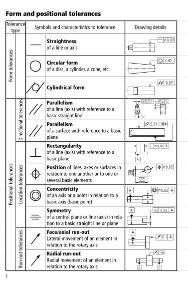
Form and positional tolerancesTolerance
typeSymbolsandcharacteristicstotolerance Drawingdetails Explanation Tolerancezone
Form
tole
ranc
es
Straightnessofalineoraxis
Theaxisofthecylindricalpartofthepinmustliewithinthecylindertot=0.03mm
Circular formofadisc,acylinder,acone,etc.
Thecircumferencelineofanycrosssectionmustbecontainedinacircularringwithawidthtot=0.02mm
Cylindrical form Thesurfacetotolerancemustliewithintwocoaxialcylinderswhichhavearadialspacingtot=0.05mm
Posi
tiona
ltol
eran
ces
Dire
ctio
nalt
oler
ance
s
Parallelismofaline(axis)withreferencetoabasicstraightline
Thetopaxismustlieinasquare-shapedarea,within0.�mmintheverticaland0.2mminthehorizontaldirection.TheareawilllieparalleltothebasicaxisofboreA.
Parallelismofasurfacewithreferencetoabasicplane
Any�00mmlongsectionofthetopsurfacemustliewithagapof0.0�mmbetweentwoparallelplanes.Theplaneswilllieparalleltothelowersurface(basicsurface).
Loca
tion
tole
ranc
es
Rectangularityofaline(axis)withreferencetoabasicplane
Theaxisofthecylindermustlieinacylindricalareawithadia-meterof0.0�mm.TheareawillbeverticaltothebasicplaneA.
Positionoflines,axesorsurfacesinrelationtooneanotherortooneorseveralbasicelements
Theaxisoftheholemustliewithinacylinderwithadiametertotolerancet=0.05mm,whoseaxisliesattheprecisegeometricalplace(withdimensionsasshowninboxes).
Concentricityofanaxisorapointinrelationtoabasicaxis(basicpoint)
Theaxisofthepartoftheshafttotolerancemustliewithinacylinderwithadiametertotolerancet=0.03mm,whoseaxisalignswiththebaseaxis.
Symmetryofacentralplaneorline(axis)inrela-tiontoabasicstraightlineorplane
Thecentralplaneoftheslotmustliebetweentwoparallelplaneswhicharespacedtot=0.08mmandbesymmetricaltothecentralplaneofthebase.
Run-
outt
oler
ance
s Face/axial run-out Lateralmovementofanelementinrelationtotherotaryaxis
Thelateralrun-outofthefacesurfaceshouldnotexceedtolerancet=0.�mmwhentheworkpiecerotatesaroundthebasicaxisA.
Radial run-outRadialmovementofanelementinrelationtotherotaryaxis
Theconcentricitydeviationmustnotbegreaterthan0.�mminanymeasurementplaneforacompleterevolutionaroundthesharedbasicaxisofcylinderAandB.

3
Tolerancetype
Symbolsandcharacteristicstotolerance Drawingdetails Explanation Tolerancezone
Form
tole
ranc
es
Straightnessofalineoraxis
Theaxisofthecylindricalpartofthepinmustliewithinthecylindertot=0.03mm
Circular formofadisc,acylinder,acone,etc.
Thecircumferencelineofanycrosssectionmustbecontainedinacircularringwithawidthtot=0.02mm
Cylindrical form Thesurfacetotolerancemustliewithintwocoaxialcylinderswhichhavearadialspacingtot=0.05mm
Posi
tiona
ltol
eran
ces
Dire
ctio
nalt
oler
ance
s
Parallelismofaline(axis)withreferencetoabasicstraightline
Thetopaxismustlieinasquare-shapedarea,within0.�mmintheverticaland0.2mminthehorizontaldirection.TheareawilllieparalleltothebasicaxisofboreA.
Parallelismofasurfacewithreferencetoabasicplane
Any�00mmlongsectionofthetopsurfacemustliewithagapof0.0�mmbetweentwoparallelplanes.Theplaneswilllieparalleltothelowersurface(basicsurface).
Loca
tion
tole
ranc
es
Rectangularityofaline(axis)withreferencetoabasicplane
Theaxisofthecylindermustlieinacylindricalareawithadia-meterof0.0�mm.TheareawillbeverticaltothebasicplaneA.
Positionoflines,axesorsurfacesinrelationtooneanotherortooneorseveralbasicelements
Theaxisoftheholemustliewithinacylinderwithadiametertotolerancet=0.05mm,whoseaxisliesattheprecisegeometricalplace(withdimensionsasshowninboxes).
Concentricityofanaxisorapointinrelationtoabasicaxis(basicpoint)
Theaxisofthepartoftheshafttotolerancemustliewithinacylinderwithadiametertotolerancet=0.03mm,whoseaxisalignswiththebaseaxis.
Symmetryofacentralplaneorline(axis)inrela-tiontoabasicstraightlineorplane
Thecentralplaneoftheslotmustliebetweentwoparallelplaneswhicharespacedtot=0.08mmandbesymmetricaltothecentralplaneofthebase.
Run-
outt
oler
ance
s Face/axial run-out Lateralmovementofanelementinrelationtotherotaryaxis
Thelateralrun-outofthefacesurfaceshouldnotexceedtolerancet=0.�mmwhentheworkpiecerotatesaroundthebasicaxisA.
Radial run-outRadialmovementofanelementinrelationtotherotaryaxis
Theconcentricitydeviationmustnotbegreaterthan0.�mminanymeasurementplaneforacompleterevolutionaroundthesharedbasicaxisofcylinderAandB.

4
1 2 3 4 5 6 7 8 9 10 11 12
�-3 0,8 �,2 2 3 4 6 �0 �4 25 40 60 �00
>3-6 � �,5 2,5 4 5 8 �2 �8 30 48 75 �20
>6-�0 � �,5 2,5 4 6 9 �5 22 36 58 90 �50
>�0-�8 �,2 2 3 5 8 �� �8 27 43 70 ��0 �80
>�8-30 �,5 2,5 4 6 9 �3 2� 33 52 84 �30 2�0
>30-50 �,5 2,5 4 7 �� �6 25 39 62 �00 �60 250
>50-80 2 3 5 8 �3 �9 30 46 74 �20 �90 300
>80-�20 2,5 4 6 �0 �5 22 35 54 87 �40 220 350
>�20-�80 3,5 5 8 �2 �8 25 40 63 �00 �60 250 400
>�80-250 4,5 7 �0 �4 20 29 46 72 ��5 �85 290 460
>250-3�5 6 8 �2 �6 23 32 52 8� �30 2�0 320 520
IT tolerance class
Nominaldimension
rangemm
IT tolerance class

5
+�50
+�00
+50
0
–50
–�00
µm
–�50
+�00
+50
0
–50
–�00
µm
Position of tolerance field to zero lineExample for nominal dimension range 6 to 10 mm
quality9andabove
nega
tive
dim
ensi
ons
(–)
nom
inal
dim
ensi
on
forquality3to8
zeroline
nega
tive
dim
ensi
ons
(–)
posi
tive
dim
ensi
ons
(+)
nom
inal
dim
ensi
on
zeroline
Internal dimensions (bores)
External dimensions (shafts)
posi
tive
dim
ensi
ons
(+)

6
Z 5Z 4Z 3
Z 2
Z �
R a
lm
Ra = e y dx�lm
lm
0
Rz=(Z�+Z2+Z3+Z4+Z5)�5
Surface measurementsMean surface finish Ra
Average surface uniformity Rz
Thearithmeticmeanfortheabsolutevaluesofallprofileordinateswithintheoverallmeasurementdistanceafterfilteringoutformdeviationsandcoarseripplefactorpercentage.
Arithmeticmeanfromtheindividualsurfaceuniformityvaluesoffiveadjacent,equallength,individualmeasuringdistancesafterfilteringoutformdeviationsandcoarseripplefactor.

7
N12 50 �60
N11 25 �00
N10 �2,5 63
N9 6,3 40
N8 3,225
�6
N7 �,6 �0
N6 0,86,3
4
N5 0,4 2,5
N4 0,2 �,6
N3 0,� �
N2 0,05 0,63
N1 0,025 0,25
Surfacefinishfrom:
roughmachiningnormalworkshoppracticefinemachining(achievedwithextraspecialcare)
Achievable surface finish RaSu
rface
fin
ish
clas
s
Mea
nsu
rface
fin
ish
R aAv
erag
esu
rface
uni
-fo
rmity
Rz
Drill
ing
Roug
hing
Fine
bor
ing
Ream
ing
Grin
ding
Honi
ng
Rolli
ng

8
Aerosol Advantage Disadvantage
1-ch
anne
l sys
tem •switchingbetweenMLCandstandard
coolantsystemnotaproblem•continuoussupplyofaerosol•nopollutionproblemwithinrestricted
limits•dropletsizeapprox.�µm(caution:
shouldnotbebreathedin)
•suitableforsmallboreØof<0.7mmundercertainconditions
•specialextractionequipmentrequired•longertoolchangetimesbecause
spindleneedstobevented(approx.�sec.)
•condensationfromaerosolonwalls(oilonwalls)
•onlysuitableforspindlespeedsof>�6,000min-�undercertaincondi-tions
2-ch
anne
l sys
tem
•reliableuseinproductionupto40,000min-�
•suitableforsmallborediameters•fastertoolchange(0.�secs)
•time-consumingchangeovertostan-dardcoolantsystem
•significantnegativeeffectwhenchangingdirection
•dropletsize2–5µm•extractionsystemrequiredinworking
area
Minimal lubrication (MLC)Asmachiningwithcoolantrepresentsaconsiderablecostfactorintoday’sproduc-tion,theuseofMLCoffersthepotentialtoreduceunitcosts.
MLCdoesnotinvolveanimmersionlubricationsystem,aswithlubricationusingemulsion,butisalubricationsystemusingveryfinelydistributedlubricantwhichisappliedtothecuttingedgeinastreamofair;therearebasicallytwodifferentsystemsforproducingtheaerosol.
AirsupplyLubricant
spin
dle
tool
hol
der
tool
continuousstreamofaerosol
airsupply
airsupply
oilfilm
spin
dle
tool
hol
der
tool

9
Advantage Disadvantage
1-ch
anne
l sys
tem •switchingbetweenMLCandstandard
coolantsystemnotaproblem•continuoussupplyofaerosol•nopollutionproblemwithinrestricted
limits•dropletsizeapprox.�µm(caution:
shouldnotbebreathedin)
•suitableforsmallboreØof<0.7mmundercertainconditions
•specialextractionequipmentrequired•longertoolchangetimesbecause
spindleneedstobevented(approx.�sec.)
•condensationfromaerosolonwalls(oilonwalls)
•onlysuitableforspindlespeedsof>�6,000min-�undercertaincondi-tions
2-ch
anne
l sys
tem
•reliableuseinproductionupto40,000min-�
•suitableforsmallborediameters•fastertoolchange(0.�secs)
•time-consumingchangeovertostan-dardcoolantsystem
•significantnegativeeffectwhenchangingdirection
•dropletsize2–5µm•extractionsystemrequiredinworking
area
ToolsfromtheKOMETGROUPGmbHcanalsobesuppliedinanoptimisedformforusewithminimallubrication(MLC).
FordetailspleasecontactyourKOMETapplicationsengineer,whowillbeabletoadviseyouonthetechnology.

�0
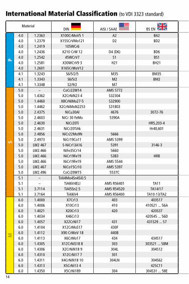
DIN AISI/SAAE BSEN AFNOR SS UNI UNE JIS
P
�.0 �.0038 RSt37-2 A570-36 436040C E24-2NE �3���.0 �.0��6 St37-3 A573-8�65 436040B E24-U �3�2�.0 �.0�44 St44-3 A573-8� 436043C E28-4 �4�2�.0 �.020� St36 �006 Fd5 ��60�.0 �.0345 H� A5�565 �50��6� A37CP �3302.0 �.040� C�5 �0�5;�0�6;�0�7 080M�5 CC�2 �350 C�5C�6 F.���2.0 �.0402 C22 �020;�023 055M�5;070M20...2C AF42C20;XC25;�C22 �450 C20;C2�;C25 �C22F.��2 S20C;S22C2.0 �.0436 Ast45 A662C �50�224 A48FP 2�032.0 �.0443 GS-45 A2765-35 A� E23-45M2.0 �.0473 �9Mn6 A537� �50�224 A52CP 2�0�2.0 �.050� C35 �035 060A35 CC35 �550 C35 F.��32.0 �.0503 C45 �043 080M46 AF65C45 �650 C45 F.5��02.0 �.0503 C45 �045 080M46 CC45 �650 C45 F.��42.0 �.05�� C40 �040 080M40 AF60C40 C40 F.��4.A2.0 �.0535 C55 �055 070M55 �655 C55 F.��52.0 �.055� GS-52 A2770-36 A2 280-480M �5052.0 �.0553 GS-60 A�4880-40 A3 320-560M �6062.0 �.0577 Ast52 A738 �50�224 A52FP 2�072.0 �.060� C60 �060 080A62...43D CC55 C602.0 �.084� St52-3 5�20 �50M�9 20MC5 2�72 Fe52 F.43�2.0 �.��2� Ck�0 �0�0 045M�0 XC�0 �265 C�0 F.�5�0-C�0K2.0 �.��33 20Mn5 �022;�5�8 �20M�9 20M5 ��32 G22Mn3;20Mn7 F.�5�5-20Mn6 SMnC4202.0 �.��4� CK�5 �0�5,�0�7 080M�5 XC�8 �370 F.�5��2.0 �.��58 C25E;Ck25 �025 070M26 2C25;XC25 �450 C25 F.��20-C25k S25C;S28C2.0 �.��83 Cf35 �035 060A35 XC38TS �572 C36 S35C2.0 �.��9� Ck45 �042 080A47 XC45 �660 C45 F.��402.0 �.�545 C�05W� W��0 BW�A Y�05 �880 C36KU F.5��8 SK32.0 �.54�5 �5Mo3 ASTMA204Gr.A �50�-240 �5D3 29�2 �6Mo3KW �6Mo3 STBA�22.0 �.5423 �6Mo5 4520 �503-245-420 �6Mo5 �6Mo52.0 �.5622 �4Ni6 ASTMA350LF5 �6N6 �4Ni6 �5Ni62.� �.07�5 9SMn28 �2�3 230M07 S250 �9�2 CF9SMn28 ��SMn28 SUM222.� �.07�8 9SMnPb28 �2L�3 S250Pb �9�4 CF9SMnPb28 ��SMnPb28 SUM22,3,4L2.� �.0722 �0SPb20 ��L08 �0PbF2 CF�0SPb20 �0SPb202.� �.0726 35S20 ��40 2�2M36...8M 35MF6 �957 F.2�0.G2.� �.0727 45S20 ��46 45MF4 �9732.� �.0736 9SMn36 �2�5 240M07...�b S300 CF9SMn36 �2SMn35 SUM252.� �.0737 9SMnPb36 �2L�4 S300Pb �926 CF9SMnPb36 �2SMnP353.0 �.0904 55Si7 9255 250A53...45 55S7 2085 55Si8 56Si73.0 �.096� 60SiCr8 9262 60SC6 60SiCr8 60SiCr83.0 �.��57 40Mn4 �039 �50M36...�5 35M53.0 �.��67 36Mn5 �335 �50M36 40M5 2�20 36Mn5 SMn438(H)3.0 �.��70 28Mn6 �330 �50M28...�4A 20M5 C28Mn SCMn�3.0 �.�203 Ck55 �055 070M55 XC55 C50 F.�203-36MnG S55C3.0 �.�2�3 Cf53 �050 060A52 XC48TS �674 C53 S50C
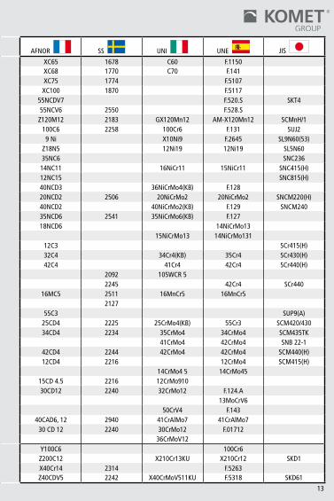
International Material Classification (toVDI3323standard)
Material

��
DIN AISI/SAAE BSEN AFNOR SS UNI UNE JIS
P
�.0 �.0038 RSt37-2 A570-36 436040C E24-2NE �3���.0 �.0��6 St37-3 A573-8�65 436040B E24-U �3�2�.0 �.0�44 St44-3 A573-8� 436043C E28-4 �4�2�.0 �.020� St36 �006 Fd5 ��60�.0 �.0345 H� A5�565 �50��6� A37CP �3302.0 �.040� C�5 �0�5;�0�6;�0�7 080M�5 CC�2 �350 C�5C�6 F.���2.0 �.0402 C22 �020;�023 055M�5;070M20...2C AF42C20;XC25;�C22 �450 C20;C2�;C25 �C22F.��2 S20C;S22C2.0 �.0436 Ast45 A662C �50�224 A48FP 2�032.0 �.0443 GS-45 A2765-35 A� E23-45M2.0 �.0473 �9Mn6 A537� �50�224 A52CP 2�0�2.0 �.050� C35 �035 060A35 CC35 �550 C35 F.��32.0 �.0503 C45 �043 080M46 AF65C45 �650 C45 F.5��02.0 �.0503 C45 �045 080M46 CC45 �650 C45 F.��42.0 �.05�� C40 �040 080M40 AF60C40 C40 F.��4.A2.0 �.0535 C55 �055 070M55 �655 C55 F.��52.0 �.055� GS-52 A2770-36 A2 280-480M �5052.0 �.0553 GS-60 A�4880-40 A3 320-560M �6062.0 �.0577 Ast52 A738 �50�224 A52FP 2�072.0 �.060� C60 �060 080A62...43D CC55 C602.0 �.084� St52-3 5�20 �50M�9 20MC5 2�72 Fe52 F.43�2.0 �.��2� Ck�0 �0�0 045M�0 XC�0 �265 C�0 F.�5�0-C�0K2.0 �.��33 20Mn5 �022;�5�8 �20M�9 20M5 ��32 G22Mn3;20Mn7 F.�5�5-20Mn6 SMnC4202.0 �.��4� CK�5 �0�5,�0�7 080M�5 XC�8 �370 F.�5��2.0 �.��58 C25E;Ck25 �025 070M26 2C25;XC25 �450 C25 F.��20-C25k S25C;S28C2.0 �.��83 Cf35 �035 060A35 XC38TS �572 C36 S35C2.0 �.��9� Ck45 �042 080A47 XC45 �660 C45 F.��402.0 �.�545 C�05W� W��0 BW�A Y�05 �880 C36KU F.5��8 SK32.0 �.54�5 �5Mo3 ASTMA204Gr.A �50�-240 �5D3 29�2 �6Mo3KW �6Mo3 STBA�22.0 �.5423 �6Mo5 4520 �503-245-420 �6Mo5 �6Mo52.0 �.5622 �4Ni6 ASTMA350LF5 �6N6 �4Ni6 �5Ni62.� �.07�5 9SMn28 �2�3 230M07 S250 �9�2 CF9SMn28 ��SMn28 SUM222.� �.07�8 9SMnPb28 �2L�3 S250Pb �9�4 CF9SMnPb28 ��SMnPb28 SUM22,3,4L2.� �.0722 �0SPb20 ��L08 �0PbF2 CF�0SPb20 �0SPb202.� �.0726 35S20 ��40 2�2M36...8M 35MF6 �957 F.2�0.G2.� �.0727 45S20 ��46 45MF4 �9732.� �.0736 9SMn36 �2�5 240M07...�b S300 CF9SMn36 �2SMn35 SUM252.� �.0737 9SMnPb36 �2L�4 S300Pb �926 CF9SMnPb36 �2SMnP353.0 �.0904 55Si7 9255 250A53...45 55S7 2085 55Si8 56Si73.0 �.096� 60SiCr8 9262 60SC6 60SiCr8 60SiCr83.0 �.��57 40Mn4 �039 �50M36...�5 35M53.0 �.��67 36Mn5 �335 �50M36 40M5 2�20 36Mn5 SMn438(H)3.0 �.��70 28Mn6 �330 �50M28...�4A 20M5 C28Mn SCMn�3.0 �.�203 Ck55 �055 070M55 XC55 C50 F.�203-36MnG S55C3.0 �.�2�3 Cf53 �050 060A52 XC48TS �674 C53 S50C

�2
DIN AISI/SAAE BSEN AFNOR SS UNI UNE JIS
P
3.0 �.�22� Ck60 �064 060A62 XC65 �678 C60 F.��503.0 �.�23� Ck67 �070 070A72 XC68 �770 C70 F.�4�3.0 �.�248 Ck75 �080 060A78 XC75 �774 F.5�073.0 �.�274 Ck�0� �095 060A96 XC�00 �870 F.5��73.0 �.27�3 55NiCrMoV6 L6 55NCDV7 F.520.S SKT43.0 �.272� 50NiCr�3 L6 55NCV6 2550 F.528.S3.0 �.340� G-X�20Mn�2 ASTMA�2875 BW�0 Z�20M�2 2�83 GX�20Mn�2 AM-X�20Mn�2 SCMnH/�3.0 �.3505 �00Cr6 52�00 534A99...3� �00C6 2258 �00Cr6 F.�3� SUJ23.0 �.5662 X8Ni9 ASMA353 502-650 9Ni X�0Ni9 F.2645 SL9N60(53)3.0 �.5680 �2Ni�9 25�5(25�7) �2Ni�9 Z�8N5 �2Ni�9 �2Ni�9 SL5N603.0 �.57�0 36NiCr6 3�35 640A35...���A 35NC6 SNC2363.0 �.5732 �4NiICr�0 34�5 �4NC�� �6NiCr�� �5NiCr�� SNC4�5(H)3.0 �.5752 �4NiICr�4 33�0 655M�3...36A �2NC�5 SNC8�5(H)3.0 �.65�� 36CrNiMo4 9840 8�6M40...��0 40NCD3 36NiCrMo4(KB) F.�283.0 �.6523 2�NiCrMo2 8620,86�7 805M20...362 20NCD2 2506 20NiCrMo2 20NiCrMo2 SNCM220(H)3.0 �.6546 40NiCrMo22 8740,8640,8742 3��-Type7 40NCD2 40NiCrMo2(KB) F.�29 SNCM2403.0 �.6582 35CrNiMo6 4340 8�7M40...24 35NCD6 254� 35NiCrMo6(KB) F.�273.0 �.6587 �7CrNiMo6 43�7 820A�6 �8NCD6 �4NiCrMo�33.0 �.6657 �4NiCrMo�3-4 93�0 832M�3...36C �5NiCrMo�3 �4NiCrMo�3�3.0 �.70�5 �5Cr3 50�5 523M�5 �2C3 SCr4�5(H)3.0 �.7033 34Cr4 5�32 530A32...�8B 32C4 34Cr4(KB) 35Cr4 SCr430(H)3.0 �.7035 4�Cr4 5�40 530M40...�8 42C4 4�Cr4 42Cr4 SCr440(H)3.0 �.7039 34MoCrS4G L� 524A�4 2092 �05WCR53.0 �.7045 42Cr4 5�40 2245 42Cr4 SCr4403.0 �.7�3� �6MnCr5 5��5 (527M20) �6MC5 25�� �6MnCr5 �6MnCr53.0 �.7�39 �6MnCr5 2�273.0 �.7�76 55Cr3 5�55 527A60...48 55C3 SUP9(A)3.0 �.72�8 25CrMo4 4�30 �7�7CDS��0 25CD4 2225 25CrMo4(KB) 55Cr3 SCM420/4303.0 �.7220 34CrMo4 4�35,4�37 34CrMo4 34CD4 2234 35CrMo4 34CrMo4 SCM435TK3.0 �.7223 4�CrMo4 4�42 4�CrMo4 42CrMo4 SNB22-�3.0 �.7225 42CrMo4 4�40 708M40...�9A 42CD4 2244 42CrMo4 42CrMo4 SCM440(H)3.0 �.7262 �5CrMo5 �2CD4 22�6 �2CrMo4 SCM4�5(H)3.0 �.7335 �3CrMo44 ASTMA�82F-�2 �4CrMo45 �4CrMo453.0 �.7337 �6CrMo44 ASTMA387�2-2 �50�620 �5CD4.5 22�6 �2CrMo9�03.0 �.736� 32CrMo�2 722M24...40B 30CD�2 2240 32CrMo�2 F.�24.A3.0 �.77�5 �4MoV63 �503-660-440 �3MoCrV63.0 �.8�59 50CrV4 6�50 50CrV4 F.�433.0 �.8509 4�CrAlMo7 ASTMA290 905M39...4�B 40CAD6,�2 2940 4�CrAlMo7 4�CrAlMo73.0 �.85�5 3�CeMo�2 722M24 30CD�2 2240 30CrMo�2 F.0�7�23.0 �.8523 39CrMoV�39 897M39...40C 36CrMoV�24.0 �.2067 �00Cr6 L3 BL3 Y�00C6 �00Cr64.0 �.2080 X2�0Cr�2 D3 BD3 Z200C�2 X2�0Cr�3KU X2�0Cr�2 SKD�4.0 �.2083 X42Cr�3 X40Cr�4 23�4 F.52634.0 �.2344 X40CrMoV5� H�3 BH�3 Z40CDV5 2242 X40CrMoV5��KU F.53�8 SKD6�
International Material Classification (toVDI3323standard)
Material
�3
DIN AISI/SAAE BSEN AFNOR SS UNI UNE JIS
P
3.0 �.�22� Ck60 �064 060A62 XC65 �678 C60 F.��503.0 �.�23� Ck67 �070 070A72 XC68 �770 C70 F.�4�3.0 �.�248 Ck75 �080 060A78 XC75 �774 F.5�073.0 �.�274 Ck�0� �095 060A96 XC�00 �870 F.5��73.0 �.27�3 55NiCrMoV6 L6 55NCDV7 F.520.S SKT43.0 �.272� 50NiCr�3 L6 55NCV6 2550 F.528.S3.0 �.340� G-X�20Mn�2 ASTMA�2875 BW�0 Z�20M�2 2�83 GX�20Mn�2 AM-X�20Mn�2 SCMnH/�3.0 �.3505 �00Cr6 52�00 534A99...3� �00C6 2258 �00Cr6 F.�3� SUJ23.0 �.5662 X8Ni9 ASMA353 502-650 9Ni X�0Ni9 F.2645 SL9N60(53)3.0 �.5680 �2Ni�9 25�5(25�7) �2Ni�9 Z�8N5 �2Ni�9 �2Ni�9 SL5N603.0 �.57�0 36NiCr6 3�35 640A35...���A 35NC6 SNC2363.0 �.5732 �4NiICr�0 34�5 �4NC�� �6NiCr�� �5NiCr�� SNC4�5(H)3.0 �.5752 �4NiICr�4 33�0 655M�3...36A �2NC�5 SNC8�5(H)3.0 �.65�� 36CrNiMo4 9840 8�6M40...��0 40NCD3 36NiCrMo4(KB) F.�283.0 �.6523 2�NiCrMo2 8620,86�7 805M20...362 20NCD2 2506 20NiCrMo2 20NiCrMo2 SNCM220(H)3.0 �.6546 40NiCrMo22 8740,8640,8742 3��-Type7 40NCD2 40NiCrMo2(KB) F.�29 SNCM2403.0 �.6582 35CrNiMo6 4340 8�7M40...24 35NCD6 254� 35NiCrMo6(KB) F.�273.0 �.6587 �7CrNiMo6 43�7 820A�6 �8NCD6 �4NiCrMo�33.0 �.6657 �4NiCrMo�3-4 93�0 832M�3...36C �5NiCrMo�3 �4NiCrMo�3�3.0 �.70�5 �5Cr3 50�5 523M�5 �2C3 SCr4�5(H)3.0 �.7033 34Cr4 5�32 530A32...�8B 32C4 34Cr4(KB) 35Cr4 SCr430(H)3.0 �.7035 4�Cr4 5�40 530M40...�8 42C4 4�Cr4 42Cr4 SCr440(H)3.0 �.7039 34MoCrS4G L� 524A�4 2092 �05WCR53.0 �.7045 42Cr4 5�40 2245 42Cr4 SCr4403.0 �.7�3� �6MnCr5 5��5 (527M20) �6MC5 25�� �6MnCr5 �6MnCr53.0 �.7�39 �6MnCr5 2�273.0 �.7�76 55Cr3 5�55 527A60...48 55C3 SUP9(A)3.0 �.72�8 25CrMo4 4�30 �7�7CDS��0 25CD4 2225 25CrMo4(KB) 55Cr3 SCM420/4303.0 �.7220 34CrMo4 4�35,4�37 34CrMo4 34CD4 2234 35CrMo4 34CrMo4 SCM435TK3.0 �.7223 4�CrMo4 4�42 4�CrMo4 42CrMo4 SNB22-�3.0 �.7225 42CrMo4 4�40 708M40...�9A 42CD4 2244 42CrMo4 42CrMo4 SCM440(H)3.0 �.7262 �5CrMo5 �2CD4 22�6 �2CrMo4 SCM4�5(H)3.0 �.7335 �3CrMo44 ASTMA�82F-�2 �4CrMo45 �4CrMo453.0 �.7337 �6CrMo44 ASTMA387�2-2 �50�620 �5CD4.5 22�6 �2CrMo9�03.0 �.736� 32CrMo�2 722M24...40B 30CD�2 2240 32CrMo�2 F.�24.A3.0 �.77�5 �4MoV63 �503-660-440 �3MoCrV63.0 �.8�59 50CrV4 6�50 50CrV4 F.�433.0 �.8509 4�CrAlMo7 ASTMA290 905M39...4�B 40CAD6,�2 2940 4�CrAlMo7 4�CrAlMo73.0 �.85�5 3�CeMo�2 722M24 30CD�2 2240 30CrMo�2 F.0�7�23.0 �.8523 39CrMoV�39 897M39...40C 36CrMoV�24.0 �.2067 �00Cr6 L3 BL3 Y�00C6 �00Cr64.0 �.2080 X2�0Cr�2 D3 BD3 Z200C�2 X2�0Cr�3KU X2�0Cr�2 SKD�4.0 �.2083 X42Cr�3 X40Cr�4 23�4 F.52634.0 �.2344 X40CrMoV5� H�3 BH�3 Z40CDV5 2242 X40CrMoV5��KU F.53�8 SKD6�
�4
DIN AISI/SAAE BSEN AFNOR SS UNI UNE JIS
P
4.0 �.2363 X�00CrMoV5� A2 BA2 Z�00CDV5 2260 X�00CrMoV5�KU F.5227 SKD�24.0 �.2379 X�55CrVMo�2� D2 BD2 Z�60CDV�2 23�0 X�55CrVMo�2�KU F.520.A SKD��4.0 �.24�9 �05WCr6 �05WC�3 2�40 �07WCr5 �05WCr5 SKS3�4.0 �.2436 X2�0CrW�2 D4(D6) BD6 Z200CD�2-0� 23�2 X2�5CrW�2�KU F.52�34.0 �.2542 45WCrV7 S� BS� 45WCrV8 27�0 45WCrV8KU F.5244.0 �.258� X30WCrV93 H2� BH2� Z30WCV9 X30WCrV93KU F.526 SKD54.0 �.260� X�65CrMoV�2 23�0 X�65CrMoW�2KU F.52��4.� �.3243 S6/5/2/5 M35 BM35 6-5-2-5 2723 HS6525 F.56�3 SKH554.� �.3343 S6/5/2 M2 BM2 Z85WDCV 2722 HS652 F.5604 SKH5�4.� �.3348 S2/9/2 M7 292 2782 HS292
S
5.0 – CoCr22W�4 AMS5772 KC225.0 �.4362 X2CrNiN234 S32304 Z2CN23-04AZ 23275.0 �.4460 X8CrNiMo27-5 S32900 23245.0 �.4462 X2CrNiMoN2253 S3�803 Z2CND22-05-03 23775.0 2.4375 NiCu30Al 4676 3072-765.0 2.4603 NiCr30FeMo 5390A NC22FeD5.0 2.4630 NiCr20Ti HR5,203-4 NC20T5.0 2.463� NiCr20TiAk Hr40,60� NC20TA5.0 2.4856 NiCr22Mo9N 5666 NC22FeDNB5.0 2.4973 NiCr�9Co�� AMS5399 NC�9KDT5.0 LW2467 S-NiCr�3A�6 539� 3�46-3 NC�2AD5.0 LW2.466 NiFe35Cr�4 5660 ZSNCDT425.0 LW2.466 NiCr�9Fe�9 5383 HR8 NC�9FeNb5.0 LW2.466 NiCr�9Fe�9 AMS5544 NC20K�45.0 LW2.467 NiCo�5Cr�0 AMS53975.0 LW2.496 CoCr20W�5 5537C KC20WN5.� – TiAl4Mo4Sn4Si0.55.� – TiAl6V4ELI AMSR5640� TA�� 5.� 3.7��4 TiAl5Sn2.5 AMSR54520 TA�4/�7 T-A5E5.� 3.7�64 TiAl6V4 AMSR56400 TA�0-�3/TA2 T-A6V
M
6.0 �.4000 X7Cr�3 403 403S�7 Z6C�3 230� X6Cr�3 F.3��0 SUS4036.0 �.4006 X�0Cr�3 4�0 4�0S2�...56A Z�0C�4 2302 X�2Cr�3 F.340� SUS4�06.0 �.402� X20Cr�3 420 420S37 Z20C�3 2303 X20Cr�36.0 �.4034 X46Cr�3 420S45...56D Z40CM 2304 X40Cr�4 F.3405 SUS420J26.0 �.4057 X22CrNi�7 43� 43�S29...57 Z�5CNi6.02 232� X�6CrNi�6 F.3427 SUS43�6.0 �.4�04 X�2CrMoS�7 430F Z�0CF�7 2383 X�0CrS�7 F.3��7 SUS430F6.0 �.4��2 X90CrMoV�8 440B6.0 �.4��3 X6CrMo�7 434 434S�7 Z8CD�7.0� 2325 X8CrMo�7 SUS4346.0 �.4305 X�2CrNiS�88 303 303S2�...58M Z�0CNF�8.09 2346 X�0CrNiS�8.09 F.3508 SUS3036.0 �.4306 X2CrNiN�89 304L 304S�2 Z2CrNi�8�0 2352 X2CrNi�8�� F.3503 SCS�96.0 �.43�0 X�2CrNi�77 30� Z�2CN�7.07 233� X�2CrNi�707 F.35�7 SUS30�6.0 �.43�� X4CrNiN�8�0 304LN 304S62 Z2CN�8.�0 237� SUS304LN6.0 �.43�3 X5CrNi�34 425C�� Z4CND�3.4M SCS56.0 �.4350 X5CrNi�89 304 304S3�...58E Z6CN�8.09 2332/2333 X5CrNi�8�0 F.355� SUS304
International Material Classification (toVDI3323standard)
Material

�5
DIN AISI/SAAE BSEN AFNOR SS UNI UNE JIS
P
4.0 �.2363 X�00CrMoV5� A2 BA2 Z�00CDV5 2260 X�00CrMoV5�KU F.5227 SKD�24.0 �.2379 X�55CrVMo�2� D2 BD2 Z�60CDV�2 23�0 X�55CrVMo�2�KU F.520.A SKD��4.0 �.24�9 �05WCr6 �05WC�3 2�40 �07WCr5 �05WCr5 SKS3�4.0 �.2436 X2�0CrW�2 D4(D6) BD6 Z200CD�2-0� 23�2 X2�5CrW�2�KU F.52�34.0 �.2542 45WCrV7 S� BS� 45WCrV8 27�0 45WCrV8KU F.5244.0 �.258� X30WCrV93 H2� BH2� Z30WCV9 X30WCrV93KU F.526 SKD54.0 �.260� X�65CrMoV�2 23�0 X�65CrMoW�2KU F.52��4.� �.3243 S6/5/2/5 M35 BM35 6-5-2-5 2723 HS6525 F.56�3 SKH554.� �.3343 S6/5/2 M2 BM2 Z85WDCV 2722 HS652 F.5604 SKH5�4.� �.3348 S2/9/2 M7 292 2782 HS292
S
5.0 – CoCr22W�4 AMS5772 KC225.0 �.4362 X2CrNiN234 S32304 Z2CN23-04AZ 23275.0 �.4460 X8CrNiMo27-5 S32900 23245.0 �.4462 X2CrNiMoN2253 S3�803 Z2CND22-05-03 23775.0 2.4375 NiCu30Al 4676 3072-765.0 2.4603 NiCr30FeMo 5390A NC22FeD5.0 2.4630 NiCr20Ti HR5,203-4 NC20T5.0 2.463� NiCr20TiAk Hr40,60� NC20TA5.0 2.4856 NiCr22Mo9N 5666 NC22FeDNB5.0 2.4973 NiCr�9Co�� AMS5399 NC�9KDT5.0 LW2467 S-NiCr�3A�6 539� 3�46-3 NC�2AD5.0 LW2.466 NiFe35Cr�4 5660 ZSNCDT425.0 LW2.466 NiCr�9Fe�9 5383 HR8 NC�9FeNb5.0 LW2.466 NiCr�9Fe�9 AMS5544 NC20K�45.0 LW2.467 NiCo�5Cr�0 AMS53975.0 LW2.496 CoCr20W�5 5537C KC20WN5.� – TiAl4Mo4Sn4Si0.55.� – TiAl6V4ELI AMSR5640� TA�� 5.� 3.7��4 TiAl5Sn2.5 AMSR54520 TA�4/�7 T-A5E5.� 3.7�64 TiAl6V4 AMSR56400 TA�0-�3/TA2 T-A6V
M
6.0 �.4000 X7Cr�3 403 403S�7 Z6C�3 230� X6Cr�3 F.3��0 SUS4036.0 �.4006 X�0Cr�3 4�0 4�0S2�...56A Z�0C�4 2302 X�2Cr�3 F.340� SUS4�06.0 �.402� X20Cr�3 420 420S37 Z20C�3 2303 X20Cr�36.0 �.4034 X46Cr�3 420S45...56D Z40CM 2304 X40Cr�4 F.3405 SUS420J26.0 �.4057 X22CrNi�7 43� 43�S29...57 Z�5CNi6.02 232� X�6CrNi�6 F.3427 SUS43�6.0 �.4�04 X�2CrMoS�7 430F Z�0CF�7 2383 X�0CrS�7 F.3��7 SUS430F6.0 �.4��2 X90CrMoV�8 440B6.0 �.4��3 X6CrMo�7 434 434S�7 Z8CD�7.0� 2325 X8CrMo�7 SUS4346.0 �.4305 X�2CrNiS�88 303 303S2�...58M Z�0CNF�8.09 2346 X�0CrNiS�8.09 F.3508 SUS3036.0 �.4306 X2CrNiN�89 304L 304S�2 Z2CrNi�8�0 2352 X2CrNi�8�� F.3503 SCS�96.0 �.43�0 X�2CrNi�77 30� Z�2CN�7.07 233� X�2CrNi�707 F.35�7 SUS30�6.0 �.43�� X4CrNiN�8�0 304LN 304S62 Z2CN�8.�0 237� SUS304LN6.0 �.43�3 X5CrNi�34 425C�� Z4CND�3.4M SCS56.0 �.4350 X5CrNi�89 304 304S3�...58E Z6CN�8.09 2332/2333 X5CrNi�8�0 F.355� SUS304

�6
DIN AISI/SAAE BSEN AFNOR SS UNI UNE JIS
M
6.0 �.440� X5CrNiMo�8�0 3�6 3�6S�6...58J Z2CND�7.�� 2347 X5CrNiMo�7�2 F.3543 SUS3�66.� �.4429 X2CrNiMoN�8�3 3�6LN Z2CND�7.�3 2375 SUS3�6LN6.� �.4435 X2CrNiMo�8�2 3�6L 3�6S�3 Z2CND�7.�2 2353 X2CrNiMo�7�26.� �.4438 X2CrNiMo�8�6 3�7L 3�7S�2 Z2CND�9.�5 2367 X2CrNiMo�8�66.� �.454� X�0CrNiTi�89 32� 32�S�2...58B Z6CNT�8.�0 2337 X6CrNiTi�8�� F.3553 SUS32�6.� �.4542/�.4548 X5CrNiCuNb�7-4-4 630 Z7CNU�7-046.� �.4550 X�0CrNiNb 347 347S�7...58F Z6CNNb�8.�0 2338 X6CrNiNb�8�� F.3552 SUS3476.� �.4568/�.4504 X�2CrNiAl�77 �7-7PH 3�6S��� Z8CNA�7-07 X2CrNiMo�7�26.� �.457� X�0CrNiMoTi�8 3�6Ti 320S�7...58J Z6NDT�7.�2 2350 X6CrNiMoTi�7�2 F.35356.� �.4583 X�0CrNiMoNb�8 3�8 Z6CNDNb�7�3B X6CrNiMoNb �7�37.0 �.47�8 X45CrSi93 HW3 40�S45...52 Z45CS9 X45CrSi8 F.3220 SUH�7.0 �.4724 X�0CrA��3 405 403S�7 Z�0C�3 X�0CrA��2 F.3�� SUS4057.0 �.4742 X�0CrA��8 430 439S�5...60 Z�0CAS�8 X8Cr�7 F.3��3 SUS4307.0 �.4747 X80CrNiSi20 HNV6 443S65...59 Z80CSN20.02 X80CrSiNi20 F.320B SUH47.0 �.4762 X�0CrA�24 446 Z�0CAS24 2322 X�6Cr26 SUH4467.0 �.4828 X�5CrNiSi20�2 309 309S24 Z�5CNS20.�2 SUH3097.0 �.4845 X�2CrNi252� 3�0S 3�0S24 Z�2CN2520 236� X6CrNi2520 F.33� SUH3�07.0 �.4864 X�2NiCrSi 330 Z�2NCS35.�6 SUH3307.0 �.4865 G-X40NiCrSi 330C�� XG50NiCr SCH�57.0 �.487� X53CrMnNiN2�9 EV8 349S54 Z52CMN2�.09 X53CrMnNiN SUH35,SUH36
K
8.0 0.60�0 GG�0 A4820B Ft�0D 0��0-00 G�0 FG�08.0 0.60�5 GG�5 A4825B Grade�50 Ft�5D 0��5-00 G�4 FG�58.0 0.6020 GG20 A4830B Grade220 Ft20D 0�20-00 G20 FG208.0 0.6025 GG25 A4835B Grade260 Ft25D 0�25-00 G25 FG258.0 0.6030 GG30 A4845B Grade300 Ft30D 0�30-00 G30 FG308.0 0.6035 GG35 A4850B Grade350 Ft35D 0�35-00 G35 FG358.0 0.6040 GG40 A4860B Grade400 Ft40D 0�40-00
9.0 0.7033 GGG35.3 07�7-�9.0 0.7040 GGG40 60-40-�8 SNG420/�2 FGS400-�2 07�7-02 GS400-�2 FCD409.0 0.7043 GGG40.3 0.7043 SNG370/�7 FGS370-�7 07�7-�5 GSO42/�59.0 0.7050 GGG50 80-55-06 SNG500/7 FGS500-7 0727-02 GS500/7 FCD509.0 0.7060 GGG60 SNG600/3 FGS600-3 0732-03 GS600/3 FCD609.0 0.7070 GGG70 �00-70-03 SNG700/2 FGS700-2 0737-0� GS700/2 FCD709.0 0.8�35 GTS-35 325�0 B340/�2 MN35-�0 08�59.0 0.8�45 GTS-45 400�0 P440/7 08529.0 0.8�55 GTS-55 50005 P5�0/4 MP50-5 08549.0 0.8�65 GTS-65 70003 P570/3 MP60-3 0858
N
�4.0 3.2�62 GD-AlSi8Cu3 A380.� LM24 4250�4.0 3.238� G-AlSi�0Mg A360.2 LM9 4253�4.0 3.258� G-AlSi�2 A4�3.2 LM6 426��4.0 3.2583 G-AlSi�2(Cu) A4�3.� LM20 4260�4.0 3.2982 GD-AlSi�2 A4�3.0 4247
International Material Classification (toVDI3323standard)
Material

�7
DIN AISI/SAAE BSEN AFNOR SS UNI UNE JIS
M
6.0 �.440� X5CrNiMo�8�0 3�6 3�6S�6...58J Z2CND�7.�� 2347 X5CrNiMo�7�2 F.3543 SUS3�66.� �.4429 X2CrNiMoN�8�3 3�6LN Z2CND�7.�3 2375 SUS3�6LN6.� �.4435 X2CrNiMo�8�2 3�6L 3�6S�3 Z2CND�7.�2 2353 X2CrNiMo�7�26.� �.4438 X2CrNiMo�8�6 3�7L 3�7S�2 Z2CND�9.�5 2367 X2CrNiMo�8�66.� �.454� X�0CrNiTi�89 32� 32�S�2...58B Z6CNT�8.�0 2337 X6CrNiTi�8�� F.3553 SUS32�6.� �.4542/�.4548 X5CrNiCuNb�7-4-4 630 Z7CNU�7-046.� �.4550 X�0CrNiNb 347 347S�7...58F Z6CNNb�8.�0 2338 X6CrNiNb�8�� F.3552 SUS3476.� �.4568/�.4504 X�2CrNiAl�77 �7-7PH 3�6S��� Z8CNA�7-07 X2CrNiMo�7�26.� �.457� X�0CrNiMoTi�8 3�6Ti 320S�7...58J Z6NDT�7.�2 2350 X6CrNiMoTi�7�2 F.35356.� �.4583 X�0CrNiMoNb�8 3�8 Z6CNDNb�7�3B X6CrNiMoNb �7�37.0 �.47�8 X45CrSi93 HW3 40�S45...52 Z45CS9 X45CrSi8 F.3220 SUH�7.0 �.4724 X�0CrA��3 405 403S�7 Z�0C�3 X�0CrA��2 F.3�� SUS4057.0 �.4742 X�0CrA��8 430 439S�5...60 Z�0CAS�8 X8Cr�7 F.3��3 SUS4307.0 �.4747 X80CrNiSi20 HNV6 443S65...59 Z80CSN20.02 X80CrSiNi20 F.320B SUH47.0 �.4762 X�0CrA�24 446 Z�0CAS24 2322 X�6Cr26 SUH4467.0 �.4828 X�5CrNiSi20�2 309 309S24 Z�5CNS20.�2 SUH3097.0 �.4845 X�2CrNi252� 3�0S 3�0S24 Z�2CN2520 236� X6CrNi2520 F.33� SUH3�07.0 �.4864 X�2NiCrSi 330 Z�2NCS35.�6 SUH3307.0 �.4865 G-X40NiCrSi 330C�� XG50NiCr SCH�57.0 �.487� X53CrMnNiN2�9 EV8 349S54 Z52CMN2�.09 X53CrMnNiN SUH35,SUH36
K
8.0 0.60�0 GG�0 A4820B Ft�0D 0��0-00 G�0 FG�08.0 0.60�5 GG�5 A4825B Grade�50 Ft�5D 0��5-00 G�4 FG�58.0 0.6020 GG20 A4830B Grade220 Ft20D 0�20-00 G20 FG208.0 0.6025 GG25 A4835B Grade260 Ft25D 0�25-00 G25 FG258.0 0.6030 GG30 A4845B Grade300 Ft30D 0�30-00 G30 FG308.0 0.6035 GG35 A4850B Grade350 Ft35D 0�35-00 G35 FG358.0 0.6040 GG40 A4860B Grade400 Ft40D 0�40-00
9.0 0.7033 GGG35.3 07�7-�9.0 0.7040 GGG40 60-40-�8 SNG420/�2 FGS400-�2 07�7-02 GS400-�2 FCD409.0 0.7043 GGG40.3 0.7043 SNG370/�7 FGS370-�7 07�7-�5 GSO42/�59.0 0.7050 GGG50 80-55-06 SNG500/7 FGS500-7 0727-02 GS500/7 FCD509.0 0.7060 GGG60 SNG600/3 FGS600-3 0732-03 GS600/3 FCD609.0 0.7070 GGG70 �00-70-03 SNG700/2 FGS700-2 0737-0� GS700/2 FCD709.0 0.8�35 GTS-35 325�0 B340/�2 MN35-�0 08�59.0 0.8�45 GTS-45 400�0 P440/7 08529.0 0.8�55 GTS-55 50005 P5�0/4 MP50-5 08549.0 0.8�65 GTS-65 70003 P570/3 MP60-3 0858
N
�4.0 3.2�62 GD-AlSi8Cu3 A380.� LM24 4250�4.0 3.238� G-AlSi�0Mg A360.2 LM9 4253�4.0 3.258� G-AlSi�2 A4�3.2 LM6 426��4.0 3.2583 G-AlSi�2(Cu) A4�3.� LM20 4260�4.0 3.2982 GD-AlSi�2 A4�3.0 4247

1.�
Drilling · Roughing · Fine boringCutting Materials

1.�
1.4–1.7
•KUBQuatron® 1.10–1.15•KUBTrigon® 1.16–1.�1
1.��–1.�51.�6–1.�0
•KUBDuon® 1.��–1.�61.�7–1.471.48–1.5�1.�1–1.��
•TwinKom® 1.56–1.70
1.711.7�1.74
•UniTurn® 1.78–1.791.80–1.811.86–1.87
1.91
1.9�–1.951.96–1.97
Index:
Recommendedcuttingdata(Guidelines) Left-handfoldpageFormulae·Performationcalculation·Specialcuttingforce
Drilling
•KUB®drill•KUBCentron®/KUB®drillheadV464
•TechnicalNotes•Problems–Possiblecauses–Solutions•Chipformation
Roughing
•TechnicalNotes•Problems–Possiblecauses–Solutions•Chipformation
Fine boring•Toolswithinserts•Chipformation
Cutting materials•Guidelinesforselectinginserts•Numericalcoding•Typesofwearoninserts
1.4
DdFc
Ff
kc1.1
Md
nPc
Pa
ffz
Ff
kc
vc
vf
zp
h
Lllalunth
tana=
sina=
cosa=
a
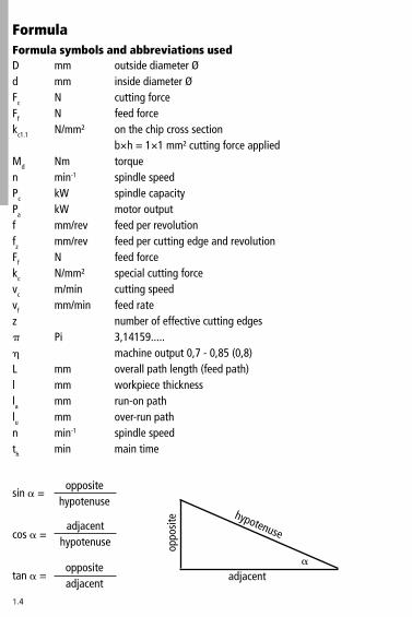
FormulaFormula symbols and abbreviations used
hypotenuse
adjacent
oppo
site
outsidediameterØinsidediameterØcuttingforcefeedforceonthechipcrosssectionb×h=1×1mm²cuttingforceappliedtorquespindlespeedspindlecapacitymotoroutputfeedperrevolutionfeedpercuttingedgeandrevolutionfeedforcespecialcuttingforcecuttingspeedfeedratenumberofeffectivecuttingedges�,14159.....machineoutput0,7-0,85(0,8)overallpathlength(feedpath)workpiecethicknessrun-onpathover-runpathspindlespeedmaintime
mmmmNNN/mm²
Nmmin-1
kWkWmm/revmm/revNN/mm²m/minmm/min
Pi
mmmmmmmmmin-1
min
oppositehypotenuse
adjacenthypotenuse
oppositeadjacent

1.5
vc×1000D×p
n=
D×p×n1000
vc=
Lf×n
th=
L=l+la+lu
vf=f×n
f=fz×z
D�
fc= ×fz×z×kc
fc×(D–d)4000
Md=
fc×
1000Md=
D4
Roughing, fine boring, reaming, coutersinking
cuttingspeedinm/min
spindlespeedinmin-1
maintimeinmin
overallpathlength(feedpath)inmm
feedrateinmm/min
feedperrevolutioninmm
General Formulae
Drilling with insert drills (KUBTrigon®,KUBQuatron®,KUBCentron®)
torqueinNm
torqueinNm
cuttingforceinN

1.6
fc×vc
60000Pc=
Md×n9554
Pc=
Pc
hPa=
D�
×fz×z×kcFf~0,7×
fc×vc×(1+
1000Pc=
dD )
Pc
hPa=
D�
×fz×z×kcFf~0,7×
Performation Calculation
Drilling with insert drills (KUBTrigon®,KUBQuatron®,KUBCentron®)
Roughing, fine boring, reaming, coutersinking
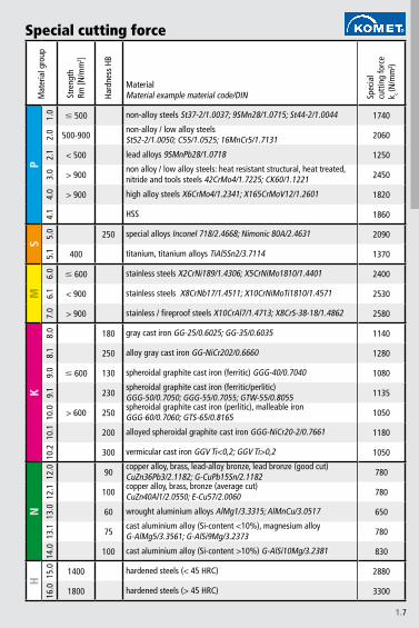
Special cutting force kcThekcvaluesdependonthefeedrate.Thetablethereforeshowstheupperlimitsforthese.Thismeanstheperformancefigurecalculatedmaybeslightlyhigher(~10–�0%)thantheactualperformancerequired.Thisisnecessarybecauseofthevaria-tionintheeffectivelevelandprovidesasafeguardagainstbadresults.
cuttingpowerinkW
cuttingpowerinkW
drivepowerinkW
feedforceinN
cuttingpowerinkW
drivepowerinkW
feedforceinN
1.7
P1.
0
#500 1740
�.0 500-900 �060
�.1 <500 1�50
�.0 >900 �450
4.0 >900 18�0
4.1 1860
S5.
0 �50 �090
5.1 400 1�70
M6.
0
#600 �400
6.1 <900 �5�0
7.0 >900 �580
K8.
0 180 1140
8.1 �50 1�80
9.0
#600 1�0 1080
9.1 ��0 11�5
10.0 >600 �50 1050
10.1 �00 1180
10.� �00 1050
N1�
.0 90 780
1�.1 100 780
1�.0 60 650
1�.1 75 780
14.0 100 8�0
H 15.0 1400 �880
16.0 1800 ��00
Special cutting forceM
ater
ialg
roup
Stre
ngth
Rm
[N/m
m� ]
Hard
ness
HB
MaterialMaterialexamplematerialcode/DIN Sp
ecia
lcu
ttin
gfo
rce
k c(N
/mm
²)
non-alloysteelsSt�7-�/1.00�7;9SMn�8/1.0715;St44-�/1.0044
non-alloy/lowalloysteelsSt5�-�/1.0050;C55/1.05�5;16MnCr5/1.71�1
leadalloys9SMnPb�8/1.0718
nonalloy/lowalloysteels:heatresistantstructural,heattreated,nitrideandtoolssteels4�CrMo4/1.7��5;CK60/1.1��1
highalloysteelsX6CrMo4/1.��41;X165CrMoV1�/1.�601
HSS
specialalloysInconel718/�.4668;Nimonic80A/�.46�1
titanium,titaniumalloysTiAl5Sn�/�.7114
stainlesssteelsX�CrNi189/1.4�06;X5CrNiMo1810/1.4401
stainlesssteelsX8CrNb17/1.4511;X10CrNiMoTi1810/1.4571
stainless/fireproofsteelsX10CrAl7/1.471�;X8CrS-�8-18/1.486�
graycastironGG-�5/0.60�5;GG-�5/0.60�5
alloygraycastironGG-NiCr�0�/0.6660
spheroidalgraphitecastiron(ferritic)GGG-40/0.7040
spheroidalgraphitecastiron(ferritic/perlitic)GGG-50/0.7050;GGG-55/0.7055;GTW-55/0.8055spheroidalgraphitecastiron(perlitic),malleableironGGG-60/0.7060;GTS-65/0.8165
alloyedspheroidalgraphitecastironGGG-NiCr�0-�/0.7661
vermicularcastironGGVTi<0,�;GGVTi>0,�
copperalloy,brass,lead-alloybronze,leadbronze(goodcut)CuZn�6Pb�/�.118�;G-CuPb15Sn/�.118�copperalloy,brass,bronze(averagecut)CuZn40Al1/�.0550;E-Cu57/�.0060
wroughtaluminiumalloysAlMg1/�.��15;AlMnCu/�.0517
castaluminiumalloy(Si-content<10%),magnesiumalloyG-AlMg5/�.�561;G-AlSi9Mg/�.��7�
castaluminiumalloy(Si-content>10%)G-AlSi10Mg/�.��81
hardenedsteels(<45HRC)
hardenedsteels(>45HRC)
1.�
Drilling · Inserts
1.�
KU
B Q
uatr
on®
KU
B Tr
igon
®
KU
B Ce
ntro
n®
KU
B®
V46
4
KU
B D
uon®
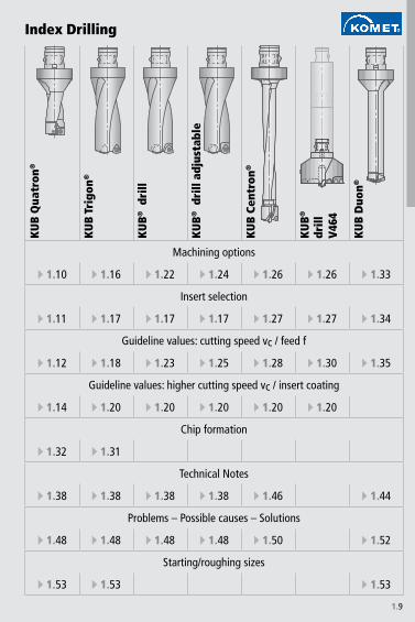
E 1.10 E 1.16 E 1.22 E 1.24 E 1.26 E 1.26 E 1.33
E 1.11 E 1.17 E 1.17 E 1.17 E 1.27 E 1.27 E 1.34
E 1.12 E 1.1� E 1.23 E 1.25 E 1.2� E 1.30 E 1.35
E 1.14 E 1.20 E 1.20 E 1.20 E 1.20 E 1.20
E 1.32 E 1.31
E 1.3� E 1.3� E 1.3� E 1.3� E 1.46 E 1.44
E 1.4� E 1.4� E 1.4� E 1.4� E 1.50 E 1.52
E 1.53 E 1.53 E 1.53
KU
B® d
rill
KU
B® d
rill
adju
stab
le
drill
Machining options
Insert selection
Guideline values: cutting speed vc / feed f
Guideline values: higher cutting speed vc / insert coating
Chip formation
Technical Notes
Problems – Possible causes – Solutions
Starting/roughing sizes
Index Drilling

1.10
2×D 3×D 4×D
§ § §
§ § &
§ § &
§ $ &
§ § $
§ § X
§ § X
§ § X
§ § X
$ $ X
$ $ X
Machining
solid drilling
blind hole
forge /casting skin, interface
angled start and drilling out, interrupted cut
convex
cross bore
centering bore, seam
chamber
stack plate drilling
rough boring
adjustable
Machining options: KUB Quatron®
§ very good $ good & possible: see technical notes E 1.3� X not possible

1.11
P BK�4
S BK7� BK7710
M BK2730
K BK61
N BK7710
H BK61
P BK�4 BK2730
S BK7710
M BK7�
KN BK7710
H
P BK6�
SM BK74
K BK6115
NH
P BK7�
SMK BK6�
NH
Wor
kpie
ce
mat
eria
lGeometry 01 Geometry 13 Geometry 21
Basic recommendation
alternative for better chip control
alternative for higher cutting speed E 1.14 - 1.15
alternative for greater strength
Insert selection W83
Guideline values for solid drilling with KUB Quatron® E 1.12 - 1.13

1.12
2×D
Ø 14 - Ø 15,�
Ø 16 - Ø 17,5
Ø 17,6- Ø 21,5
Ø 21,6- Ø 27
Ø 2� - Ø 33
Ø 34 - Ø 44
Ø 45 - Ø 54
Ø 55 - Ø 65
P1.
0 300 0,10 0,12 0,12 0,14 0,14 0,14 0,14 0,14
2.0 250 0,12 0,14 0,16 0,20 0,20 0,25 0,20 0,20
2.1 300 0,14 0,16 0,1� 0,25 0,25 0,30 0,25 0,25
3.0 200 0,14 0,16 0,1� 0,20 0,20 0,25 0,20 0,20
4.0 1�0 0,10 0,12 0,14 0,1� 0,1� 0,20 0,1� 0,1�
4.1 �0 0,0� 0,10 0,12 0,14 0,16 0,1� 0,14 0,16
S5.
0 60 0,06 0,0� 0,10 0,12 0,12 0,12 0,12 0,12
5.1 �0 0,06 0,0� 0,10 0,12 0,12 0,12 0,12 0,12
M6.
0 1�0 0,0� 0,10 0,12 0,14 0,14 0,16 0,14 0,14
6.1 160 0,0� 0,0� 0,12 0,16 0,16 0,20 0,16 0,16
7.0 160 0,06 0,0� 0,10 0,12 0,12 0,14 0,12 0,12
K�.
0 200 0,16 0,16 0,25 0,30 0,30 0,30 0,30 0,30
�.1 160 0,14 0,16 0,1� 0,20 0,20 0,25 0,20 0,20
�.0 1�0 0,14 0,16 0,1� 0,20 0,20 0,25 0,20 0,20
�.1 160 0,14 0,16 0,1� 0,22 0,22 0,25 0,22 0,22
10.0 140 0,14 0,16 0,1� 0,22 0,22 0,25 0,22 0,22
10.1 140 0,14 0,16 0,1� 0,22 0,25 0,25 0,22 0,25
10.2 120 0,10 0,12 0,16 0,20 0,20 0,25 0,20 0,20
N12
.0 300 0,12 0,14 0,16 0,25 0,20 0,25 0,25 0,20
12.1 400 0,0� 0,0� 0,10 0,12 0,12 0,15 0,12 0,12
13.0 600 0,0� 0,0� 0,10 0,12 0,12 0,12 0,12 0,12
13.1 300 0,10 0,12 0,14 0,16 0,16 0,20 0,16 0,16
14.0 250 0,10 0,12 0,14 0,20 0,20 0,30 0,20 0,20
H 15.0 �0 0,05 0,05 0,0� 0,10 0,10 0,10 0,10 0,10
16.0 40 0,05 0,05 0,0� 0,10 0,10 0,10 0,10 0,10
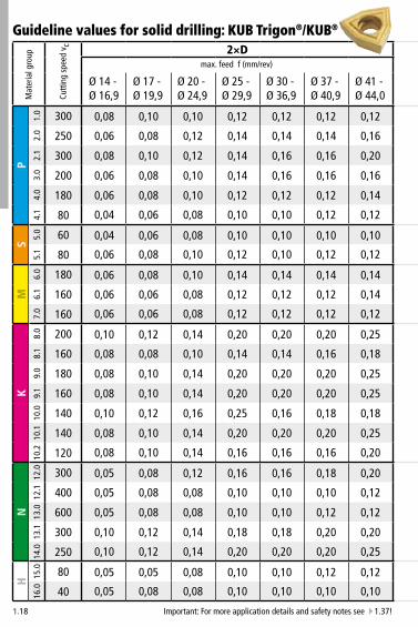
Important: For more application details and safety notes see E 1.37!
Mat
eria
l gro
up
Cutt
ing
spee
d v c
max. feed f (mm/rev)
Guideline values for solid drilling: KUB Quatron®

1.13
3×D 4×D
Ø14 -
Ø15,�
Ø16 -
Ø17,5
Ø17,6-
Ø21,5
Ø21,6-
Ø27
Ø2� -
Ø33
Ø34 -
Ø44
Ø45 -
Ø54
Ø55 -
Ø65
Ø15 -
Ø15,�
Ø16 -
Ø17,5
Ø17,6-
Ø21,5
Ø21,6-
Ø27
Ø2� -
Ø33
Ø40 -
Ø44
0,10 0,12 0,12 0,14 0,14 0,14 0,14 0,14 0,06 0,06 0,10 0,12 0,12 0,12
0,12 0,14 0,16 0,20 0,20 0,25 0,20 0,20 0,0� 0,0� 0,12 0,14 0,14 0,14
0,14 0,16 0,1� 0,25 0,25 0,30 0,25 0,25 0,10 0,10 0,16 0,20 0,20 0,16
0,14 0,16 0,1� 0,20 0,20 0,25 0,20 0,20 0,0� 0,0� 0,12 0,20 0,20 0,16
0,10 0,12 0,14 0,1� 0,1� 0,20 0,1� 0,1� 0,06 0,0� 0,12 0,16 0,16 0,14
0,0� 0,10 0,12 0,14 0,14
0,06 0,0� 0,10 0,12 0,12 0,12 0,12 0,12 0,05 0,05 0,0� 0,0� 0,0� 0,0�
0,06 0,0� 0,10 0,12 0,12 0,12 0,12 0,12 0,05 0,05 0,0� 0,0� 0,0� 0,0�
0,0� 0,10 0,12 0,14 0,14 0,16 0,14 0,14 0,06 0,06 0,10 0,14 0,16 0,16
0,0� 0,0� 0,12 0,16 0,16 0,20 0,16 0,16 0,06 0,06 0,10 0,14 0,16 0,16
0,06 0,0� 0,10 0,12 0,12 0,14 0,12 0,12 0,06 0,06 0,0� 0,12 0,16 0,16
0,16 0,16 0,25 0,30 0,30 0,30 0,30 0,30 0,14 0,16 0,20 0,25 0,30 0,20
0,14 0,16 0,1� 0,20 0,20 0,25 0,20 0,20 0,12 0,14 0,16 0,20 0,25 0,20
0,14 0,16 0,1� 0,20 0,20 0,25 0,20 0,20 0,12 0,14 0,16 0,20 0,25 0,20
0,14 0,16 0,1� 0,22 0,22 0,25 0,22 0,22 0,12 0,14 0,16 0,20 0,25 0,20
0,14 0,16 0,1� 0,22 0,22 0,25 0,22 0,22 0,12 0,14 0,16 0,20 0,25 0,20
0,14 0,16 0,1� 0,22 0,25 0,25 0,22 0,25 0,10 0,12 0,14 0,16 0,20 0,16
0,10 0,12 0,16 0,20 0,20 0,25 0,20 0,20 0,10 0,12 0,14 0,16 0,20 0,16
0,12 0,14 0,16 0,25 0,20 0,25 0,25 0,20 0,10 0,12 0,14 0,16 0,20 0,1�
0,0� 0,0� 0,10 0,12 0,12 0,15 0,12 0,12 0,0� 0,10 0,12 0,14 0,16 0,16
0,0� 0,0� 0,10 0,12 0,12 0,12 0,12 0,12 0,0� 0,10 0,12 0,12 0,12 0,10
0,10 0,12 0,14 0,16 0,16 0,20 0,16 0,16 0,10 0,12 0,14 0,16 0,16 0,16
0,10 0,12 0,14 0,20 0,20 0,30 0,20 0,20 0,12 0,14 0,16 0,20 0,20 0,16
0,05 0,05 0,0� 0,10 0,10 0,10 0,10 0,10 0,04 0,04 0,06 0,06 0,06 0,06
0,05 0,05 0,0� 0,10 0,10 0,10 0,10 0,10 0,04 0,04 0,06 0,06 0,06 0,06
max. feed f (mm/rev) max. feed f (mm/rev)

1.14
P M M K NBK�4 BK7� BK2730 BK6� BK6115 BK�4 BK7� BK2730 BK6� BK74 BK6115 BK�4 BK61 BK6115 BK7710
40 4050 5060 6070 70�0 �0�0 �0
100 100110 110120 120130 130140 140150 150160 160170 1701�0 1�01�0 1�0200 200210 210220 220230 230240 240250 250260 260270 2702�0 2�02�0 2�0300 300310 310320 320330 330340 340350 350360 360370 3703�0 3�03�0 3�0400 400410 410420 420430 430440 440450 450460 460470 4704�0 4�04�0 4�0500 500600 600700 700800 800900 9001000 10001100 1100
Cutting speedvc (m/min)
Important: For more application details and safety notes see E 1.37!
Guideline values for solid drilling: KUB Quatron®

1.15
P M M K NBK�4 BK7� BK2730 BK6� BK6115 BK�4 BK7� BK2730 BK6� BK74 BK6115 BK�4 BK61 BK6115 BK7710
40 4050 5060 6070 70�0 �0�0 �0
100 100110 110120 120130 130140 140150 150160 160170 1701�0 1�01�0 1�0200 200210 210220 220230 230240 240250 250260 260270 2702�0 2�02�0 2�0300 300310 310320 320330 330340 340350 350360 360370 3703�0 3�03�0 3�0400 400410 410420 420430 430440 440450 450460 460470 4704�0 4�04�0 4�0500 500600 600700 700800 800900 900
1000 10001100 1100
Cutting speedvc (m/min)

1.16
2×D 3×D 4×D
§ § §
§ § §
§ § $
§ § &
§ $ &
$ $ &
$ $ &
§ $ &
X X X
$ & X
§ § $
Machining
solid drilling
blind hole
forge /casting skin, interface
angled start and drilling out, interrupted cut
convex
cross bore
centering bore, seam
chamber
stack plate drilling
rough boring
adjustable
Machining options: KUB Trigon®
§ very good $ good & possible: see technical notes E 1.3� X not possible

1.17
P BK�4
S BK77
M BK7�30
K BK62
N BK77
H BK77
P BK6425 BK�4
S BK7�
M BK6425 BK7�
KNH
P BK72
SMKN BK50
H
P BK7�30 / P40
S BK7�30 / P40
M P40
K K10
N K10
H
Wor
kpie
ce
mat
eria
lGeometry 01 Geometry 03 Geometry 11 Geometry 13
only external cutting
Basic recommendation
alternative for better chip control
alternative for higher cutting speed E 1.20 - 1.21
alternative for greater strength
Insert selection W29
Guideline values for solid drilling with KUB Trigon® E 1.1� - 1.1�
1.1�
2×D
Ø 14 - Ø 16,�
Ø 17 - Ø 1�,�
Ø 20 - Ø 24,�
Ø 25 - Ø 2�,�
Ø 30 - Ø 36,�
Ø 37 - Ø 40,�
Ø 41 - Ø 44,0
P1.
0 300 0,0� 0,10 0,10 0,12 0,12 0,12 0,12
2.0 250 0,06 0,0� 0,12 0,14 0,14 0,14 0,16
2.1 300 0,0� 0,10 0,12 0,14 0,16 0,16 0,20
3.0 200 0,06 0,0� 0,10 0,14 0,16 0,16 0,16
4.0 1�0 0,06 0,0� 0,10 0,12 0,12 0,12 0,14
4.1 �0 0,04 0,06 0,0� 0,10 0,10 0,12 0,12
S5.
0 60 0,04 0,06 0,0� 0,10 0,10 0,10 0,10
5.1 �0 0,06 0,0� 0,10 0,12 0,10 0,12 0,12
M6.
0 1�0 0,06 0,0� 0,10 0,14 0,14 0,14 0,14
6.1 160 0,06 0,06 0,0� 0,12 0,12 0,12 0,14
7.0 160 0,06 0,06 0,0� 0,12 0,12 0,12 0,12
K�.
0 200 0,10 0,12 0,14 0,20 0,20 0,20 0,25
�.1 160 0,0� 0,0� 0,10 0,14 0,14 0,16 0,1�
�.0 1�0 0,0� 0,10 0,14 0,20 0,20 0,20 0,25
�.1 160 0,0� 0,10 0,14 0,20 0,20 0,20 0,25
10.0 140 0,10 0,12 0,16 0,25 0,16 0,1� 0,1�
10.1 140 0,0� 0,10 0,14 0,20 0,20 0,20 0,25
10.2 120 0,0� 0,10 0,14 0,16 0,16 0,16 0,20
N12
.0 300 0,05 0,0� 0,12 0,16 0,16 0,1� 0,20
12.1 400 0,05 0,0� 0,0� 0,10 0,10 0,10 0,12
13.0 600 0,05 0,0� 0,0� 0,10 0,10 0,12 0,12
13.1 300 0,10 0,12 0,14 0,1� 0,1� 0,20 0,20
14.0 250 0,10 0,12 0,14 0,20 0,20 0,20 0,25
H 15.0 �0 0,05 0,05 0,0� 0,10 0,10 0,12 0,12
16.0 40 0,05 0,0� 0,0� 0,10 0,10 0,10 0,10
Important: For more application details and safety notes see E 1.37!
Guideline values for solid drilling: KUB Trigon®/KUB®M
ater
ial g
roup
Cutt
ing
spee
d v c
max. feed f (mm/rev)

1.1�
3×D 4×D
Ø14 -
Ø16,�
Ø17 -
Ø1�,�
Ø20 -
Ø24,�
Ø25 -
Ø2�,�
Ø30 -
Ø36,�
Ø37 -
Ø40,�
Ø41 -
Ø44,0
Ø14 -
Ø16,�
Ø17 -
Ø1�,�
Ø20 -
Ø24,�
Ø25 -
Ø2�,�
Ø30 -
Ø36,�
Ø37 -
Ø40,�
Ø41 -
Ø44,0
0,0� 0,10 0,10 0,12 0,12 0,12 0,12 0,06 0,0� 0,0� 0,10 0,10 0,10 0,10
0,06 0,0� 0,12 0,14 0,14 0,14 0,16 0,04 0,06 0,10 0,12 0,12 0,12 0,14
0,0� 0,10 0,12 0,14 0,16 0,16 0,20 0,06 0,0� 0,10 0,12 0,14 0,14 0,1�
0,06 0,0� 0,10 0,14 0,16 0,16 0,16 0,04 0,06 0,0� 0,12 0,14 0,14 0,14
0,06 0,0� 0,10 0,12 0,12 0,12 0,14 0,04 0,06 0,0� 0,10 0,10 0,10 0,12
0,04 0,06 0,0� 0,10 0,10 0,12 0,12 0,02 0,04 0,06 0,0� 0,0� 0,10 0,10
0,04 0,06 0,0� 0,10 0,10 0,10 0,10 0,02 0,04 0,06 0,0� 0,0� 0,0� 0,0�
0,06 0,0� 0,10 0,12 0,10 0,12 0,12 0,04 0,06 0,0� 0,10 0,0� 0,10 0,10
0,06 0,0� 0,10 0,14 0,14 0,14 0,14 0,04 0,06 0,0� 0,12 0,12 0,12 0,12
0,06 0,06 0,0� 0,12 0,12 0,12 0,14 0,04 0,04 0,06 0,10 0,10 0,10 0,12
0,06 0,06 0,0� 0,12 0,12 0,12 0,12 0,04 0,04 0,06 0,10 0,10 0,10 0,12
0,10 0,12 0,14 0,20 0,20 0,20 0,25 0,0� 0,10 0,12 0,1� 0,1� 0,1� 0,23
0,0� 0,0� 0,10 0,14 0,14 0,16 0,1� 0,06 0,06 0,0� 0,12 0,12 0,14 0,16
0,0� 0,10 0,14 0,20 0,20 0,20 0,25 0,06 0,0� 0,12 0,1� 0,1� 0,1� 0,23
0,0� 0,10 0,14 0,20 0,20 0,20 0,25 0,06 0,0� 0,12 0,1� 0,1� 0,1� 0,23
0,10 0,12 0,16 0,25 0,16 0,1� 0,1� 0,0� 0,10 0,14 0,23 0,23 0,23 0,23
0,0� 0,10 0,14 0,20 0,20 0,20 0,25 0,06 0,0� 0,12 0,1� 0,1� 0,1� 0,23
0,0� 0,10 0,14 0,16 0,16 0,16 0,20 0,06 0,0� 0,12 0,14 0,14 0,14 0,1�
0,05 0,0� 0,12 0,16 0,16 0,1� 0,20 0,03 0,06 0,10 0,14 0,14 0,16 0,1�
0,05 0,0� 0,0� 0,10 0,10 0,10 0,12 0,03 0,06 0,06 0,0� 0,0� 0,0� 0,10
0,05 0,0� 0,0� 0,10 0,10 0,12 0,12 0,03 0,06 0,06 0,0� 0,0� 0,10 0,10
0,10 0,12 0,14 0,1� 0,1� 0,20 0,20 0,0� 0,10 0,12 0,16 0,16 0,1� 0,1�
0,10 0,12 0,14 0,20 0,20 0,20 0,25 0,0� 0,10 0,12 0,1� 0,1� 0,1� 0,23
0,05 0,05 0,0� 0,10 0,10 0,12 0,12 0,03 0,03 0,06 0,0� 0,0� 0,10 0,10
0,05 0,0� 0,0� 0,10 0,10 0,10 0,10 0,03 0,06 0,06 0,0� 0,0� 0,0� 0,0�
max. feed f (mm/rev) max. feed f (mm/rev)

1.20
P M K NP25M P40 BK7� BK7�30 BK�4 BK60 BK64 BK6425 BK6� BK72 BK73 P40 BK7� BK7�30 BK73 K10 BK61 BK62 K10 BK77 BK7710 BK50
40 4050 5060 6070 70�0 �0�0 �0100 100110 110120 120130 130140 140150 150160 160170 1701�0 1�01�0 1�0200 200210 210220 220230 230240 240250 250260 260270 2702�0 2�02�0 2�0300 300310 310320 320330 330340 340350 350360 360370 3703�0 3�03�0 3�0400 400410 410420 420430 430440 440450 450460 460470 4704�0 4�04�0 4�0500 500600 600700 700800 800900 900
1000 10001100 1100
Cutting speedvc (m/min)
Important: For more application details and safety notes see E 1.37!
Guideline values for solid drilling: KUB Trigon®/KUB®
Please note max. vc values for KUB Centron® E 1.2� - 1.2�

1.21
P M K NP25M P40 BK7� BK7�30 BK�4 BK60 BK64 BK6425 BK6� BK72 BK73 P40 BK7� BK7�30 BK73 K10 BK61 BK62 K10 BK77 BK7710 BK50
40 4050 5060 6070 70�0 �0�0 �0100 100110 110120 120130 130140 140150 150160 160170 1701�0 1�01�0 1�0200 200210 210220 220230 230240 240250 250260 260270 2702�0 2�02�0 2�0300 300310 310320 320330 330340 340350 350360 360370 3703�0 3�03�0 3�0400 400410 410420 420430 430440 440450 450460 460470 4704�0 4�04�0 4�0500 500600 600700 700800 800900 900
1000 10001100 1100
Cutting speedvc (m/min)
from 20m/min
up to 1500

1.22
2×D 3×D
§ §
§ §
§ §
§ $
§ $
$ $
$ $
§ $
X X
$ X
$ $
Machining
solid drilling
blind hole
forge /casting skin, interface
angled start and drilling out, interrupted cut
convex
cross bore
centering bore, seam
chamber
stack plate drilling
rough boring
adjustable
Machining options: KUB® drill
§ very good $ good & possible: see technical notes E 1.3� X not possible

1.23
2×D 3×D
Ø 45 - Ø 54
Ø 54,5 - Ø 6�
Ø 6�,5- Ø �2
Ø 45 - Ø 54
Ø 54,5 - Ø 6�
Ø 6�,5- Ø �2
P1.
0 300 0,12 0,14 0,16 0,12 0,14 0,14
2.0 250 0,16 0,20 0,25 0,16 0,20 0,20
2.1 300 0,20 0,25 0,25 0,20 0,25 0,25
3.0 200 0,16 0,20 0,20 0,16 0,1� 0,1�
4.0 1�0 0,14 0,16 0,16 0,14 0,14 0,16
4.1
S5.
0 60 0,10 0,12 0,14 0,10 0,12 0,14
5.1 �0 0,12 0,14 0,16 0,12 0,14 0,14
M6.
0 1�0 0,14 0,16 0,16 0,14 0,14 0,16
6.1 160 0,14 0,16 0,16 0,14 0,16 0,16
7.0 160 0,12 0,16 0,1� 0,12 0,16 0,16
K�.
0 200 0,25 0,30 0,30 0,25 0,25 0,30
�.1 160 0,1� 0,30 0,30 0,1� 0,20 0,25
�.0 1�0 0,25 0,30 0,30 0,25 0,25 0,30
�.1 160 0,25 0,30 0,30 0,25 0,25 0,30
10.0 140 0,25 0,30 0,30 0,25 0,25 0,30
10.1 140 0,25 0,30 0,30 0,25 0,25 0,30
10.2 120 0,20 0,25 0,30 0,20 0,20 0,20
N12
.0 300 0,20 0,25 0,25 0,20 0,20 0,25
12.1 400 0,12 0,16 0,16 0,12 0,12 0,14
13.0 600 0,12 0,12 0,14 0,12 0,12 0,14
13.1 300 0,20 0,25 0,25 0,20 0,25 0,25
14.0 250 0,25 0,30 0,30 0,25 0,30 0,30
H 15.0 �0 0,12 0,14 0,14 0,12 0,14 0,14
16.0 40 0,10 0,10 0,10 0,10 0,10 0,10
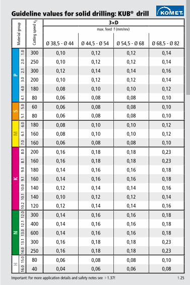
Guideline values for solid drilling: KUB® drill
Important: For more application details and safety notes see E 1.37!
Mat
eria
l gro
up
Cutt
ing
spee
d v c
max. feed f (mm/rev) max. feed f (mm/rev)

1.24
3×D
§
§
&
&
&
&
&
&
X
&
$
Machining
solid drilling
blind hole
forge /casting skin, interface
angled start and drilling out, interrupted cut
convex
cross bore
centering bore, seam
chamber
stack plate drilling
rough boring
adjustable
Machining options: KUB® drill adjustable
§ very good $ good & possible: see technical notes E 1.3� X not possible
1.25
3×D
Ø 3�,5 - Ø 44 Ø 44,5 - Ø 54 Ø 54,5 - Ø 6� Ø 6�,5 - Ø �2
P1.
0 300 0,10 0,12 0,12 0,14
2.0 250 0,10 0,12 0,12 0,14
2.1 300 0,12 0,14 0,14 0,16
3.0 200 0,10 0,12 0,12 0,14
4.0 1�0 0,0� 0,10 0,10 0,12
4.1 �0 0,06 0,0� 0,0� 0,10
S5.
0 60 0,06 0,0� 0,0� 0,10
5.1 �0 0,06 0,0� 0,0� 0,10
M6.
0 1�0 0,0� 0,10 0,10 0,12
6.1 160 0,0� 0,10 0,10 0,12
7.0 160 0,06 0,0� 0,0� 0,10
K�.
0 200 0,16 0,1� 0,1� 0,23
�.1 160 0,16 0,1� 0,1� 0,23
�.0 1�0 0,14 0,16 0,16 0,1�
�.1 160 0,14 0,16 0,16 0,1�
10.0 140 0,12 0,14 0,14 0,16
10.1 140 0,10 0,12 0,12 0,14
10.2 120 0,12 0,14 0,14 0,16
N12
.0 300 0,14 0,16 0,16 0,1�
12.1 400 0,14 0,16 0,16 0,1�
13.0 600 0,14 0,16 0,16 0,1�
13.1 300 0,16 0,1� 0,1� 0,23
14.0 250 0,16 0,1� 0,1� 0,23
H 15.0 �0 0,06 0,0� 0,0� 0,10
16.0 40 0,04 0,06 0,06 0,0�
Guideline values for solid drilling: KUB® drill
Important: For more application details and safety notes see E 1.37!
Mat
eria
l gro
up
Cutt
ing
spee
d v c
max. feed f (mm/rev)

1.26
KUB Centron® KUB® V464
§ §
§ §
$ $
& &
& &
& &
& &
& &
X X
X X
X §
ABS-T
Machining
solid drilling
blind hole
forge /casting skin, interface
angled start and drilling out, interrupted cut
convex
cross bore
centering bore, seam
chamber
stack plate drilling
rough boring
adjustable
Machining options: KUB Centron® / KUB® V464
§ very good $ good & possible: see technical notes E 1.46 X not possible

1.27
P BK�4
SM BK7�30
K BK62
N BK77
H
P BK�4, BK6425 BK�4
SM BK�4, BK6425 BK7�
KNH
P BK72
SM BK73
KN BK50
H
P BK7�30, P40
SM P40
K K10
N K10
H
Guideline values for solid drilling with KUB Centron® E 1.2� - 1.2� / KUB® V464 E 1.30
Insert selection W29W
orkp
iece
m
ater
ial
Geometry 01 Geometry 03 Geometry 11 Geometry 13
Basic recommendation
alternative for better chip control
alternative for higher cutting speed E 1.20 - 1.21
alternative for greater strength

1.2�
Ø 20 - Ø 25 Ø 26 - Ø 32 Ø 33 - Ø 45 Ø 46 - Ø 54 Ø 55 - Ø 64
P1.
0 250 0,0� 0,0� 0,10 0,12 0,14
2.0 200 0,10 0,12 0,12 0,14 0,16
2.1 250 0,12 0,14 0,14 0,14 0,16
3.0 1�0 0,12 0,14 0,14 0,14 0,16
4.0 160 0,0� 0,10 0,10 0,14 0,14
4.1 �0 0,07 0,07 0,07 0,0� 0,10
S5.
05.
1
M6.
0 1�0 0,07 0,10 0,10 0,10 0,12
6.1 160 0,10 0,12 0,12 0,12 0,14
7.0 120 0,0� 0,10 0,10 0,10 0,12
K�.
0 200 0,14 0,16 0,16 0,1� 0,25
�.1 160 0,12 0,14 0,14 0,15 0,20
�.0 160 0,12 0,14 0,14 0,1� 0,25
�.1 140 0,12 0,14 0,14 0,1� 0,25
10.0 120 0,12 0,14 0,14 0,1� 0,25
10.1 100 0,10 0,12 0,12 0,15 0,20
10.2 �0 0,10 0,12 0,12 0,15 0,20
N12
.0 200 0,14 0,16 0,16 0,20 0,25
12.1 250 0,0� 0,0� 0,10 0,12 0,15
13.0 350 0,07 0,07 0,07 0,10 0,12
13.1 250 0,10 0,12 0,14 0,1� 0,25
14.0 200 0,12 0,14 0,14 0,15 0,25
H 15.0
16.0
Guideline values for solid drilling: KUB Centron®
Important: For more application details and safety notes see E 1.37!
Mat
eria
l gro
up
Cutt
ing
spee
d v c 4×D to 9×D
max. feed f (mm/rev)

1.2�
Ø 65 - Ø 71 Ø 72 - Ø �1
P1.
0 300 0,10 0,12
2.0 250 0,12 0,14
2.1 250 0,14 0,16
3.0 1�0 0,14 0,16
4.0 160 0,10 0,12
4.1 �0 0,0� 0,10
S5.
05.
1
M6.
0 1�0 0,10 0,12
6.1 160 0,12 0,14
7.0 120 0,10 0,12
K�.
0 200 0,16 0,20
�.1 160 0,16 0,20
�.0 160 0,16 0,20
�.1 140 0,14 0,16
10.0 120 0,14 0,16
10.1 100 0,12 0,14
10.2 �0 0,12 0,14
N12
.0 200 0,16 0,20
12.1 250 0,0� 0,10
13.0 350 0,0� 0,10
13.1 250 0,14 0,16
14.0 200 0,12 0,14
H 15.0
16.0
Mat
eria
l gro
up
Cutt
ing
spee
d v c 4×D to 9×D
max. feed f (mm/rev)

1.30
6×D
Ø �0 - Ø �� Ø 100 - Ø 11� Ø 120 - Ø 160
P1.
0 200 0,10 0,12 0,12
2.0 1�0 0,12 0,14 0,16
2.1 200 0,12 0,14 0,16
3.0 160 0,12 0,14 0,16
4.0 140 0,12 0,14 0,16
4.1 60 0,10 0,12 0,14
S5.
05.
1
M6.
0 160 0,10 0,12 0,14
6.1 140 0,12 0,14 0,14
7.0 100 0,12 0,14 0,14
K�.
0 1�0 0,16 0,16 0,25
�.1 140 0,14 0,16 0,20
�.0 140 0,14 0,16 0,20
�.1 120 0,14 0,16 0,20
10.0 100 0,12 0,14 0,1�
10.1 �0 0,12 0,14 0,16
10.2 �0 0,12 0,14 0,16
N12
.0 1�0 0,16 0,20 0,25
12.1 200 0,0� 0,10 0,12
13.0 300 0,0� 0,10 0,12
13.1 200 0,14 0,16 0,16
14.0 160 0,12 0,14 0,14
H 15.0
16.0
Important: For more application details and safety notes see E 1.37!
Guideline values for solid drilling: KUB® V464M
ater
ial g
roup
Cutt
ing
spee
d v c
max. feed f (mm/rev)

1.31
W2� .. W2� .. W2� ..
W2� .. W2� .. W2� ..
Chip formation for various insert geometries
Tool: KUB Trigon® Ø 35 mm, 3×DMaterial: 42CrMo4V 1100 N/mm²Cutting data: vc = 200 m/min f = 0,16 mm/rev
Tool: KUB Trigon® Ø 35 mm, 3×DMaterial: structural steel St37Cutting data: vc = 300 m/min f = 0,12 mm/rev
Inserts suggested for KUB® and KUB Trigon®
Geometry 13 Geometry 13 Geometry 01 Geometry 03 Geometry 01 Geometry 01
internal external internal external internal external
Geometry 13 Geometry 13 Geometry 01 Geometry 03 Geometry 01 Geometry 01
internal external internal external internal external

1.32
W2� .. W2� .. W2� ..
W�3 .. W�3 .. W�3 ..
Tool: KUB Trigon® Ø 40 mm, 3×DMaterial: stainless steel 1.4571Cutting data: vc = 140 m/min f = 0,1 mm/rev
Tool: KUB Quatron® Ø 35 mm, 3×DMaterial: 42CrMo4V 1100 N/mm²Cutting data: vc = 140 m/min f = 0,25 mm/rev
Chip formation for various insert geometries
Inserts suggested for KUB® and KUB Trigon®
Inserts suggested for KUB Quatron®
Geometry 13 Geometry 13 Geometry 01 Geometry 03 Geometry 01 Geometry 01
internal external internal external internal external
Geometry 01 Geometry 21 Geometry 13 Geometry 13 Geometry 01 Geometry 01
internal external internal external internal external

1.33
5×D
§
§
$
&
$
$
&
X
§
&
X
Machining options: KUB Duon®
§ very good $ good & possible: see technical notes E 1.44 X not possible
Machining
solid drilling
blind hole
forge /casting skin, interface
angled start and drilling out, interrupted cut
convex
cross bore
centering bore, seam
chamber
stack plate drilling
rough boring
adjustable

1.34
P BK�440
SMK BK2715
N BK7710
H
PSMKNH
P BK�4
SMK BK�4
N BK�4
H
P BK�125, BK2740, BK�140
SMK BK�125
N BK�125
H
Insert selection H60 / H62
Guideline values for solid drilling with KUB Duon® E 1.35
Wor
kpie
ce
mat
eria
l
Basic recommendation
alternative for better chip control
alternative for higher cutting speed
alternative for greater strength

1.35
5×D
Ø 17,3 - Ø 20,7 Ø 20,� - Ø 2�,7 Ø 2�,� - Ø 36,2 Ø 36,3 - Ø 44,2
P1.
02.
0 140 0,15 0,20 0,22 0,25
2.1 160 0,15 0,20 0,22 0,25
3.0 120 0,15 0,20 0,25 0,30
4.0 100 0,15 0,1� 0,20 0,25
4.1
S5.
05.
1
M6.
06.
17.
0
K�.
0 140 0,30 0,40 0,50 0,55
�.1 100 0,20 0,30 0,40 0,50
�.0 120 0,25 0,35 0,45 0,50
�.1 100 0,20 0,30 0,40 0,45
10.0 120 0,20 0,30 0,40 0,45
10.1 100 0,25 0,35 0,45 0,50
10.2 �0 0,20 0,30 0,35 0,40
N12
.0 1�0 0,30 0,40 0,45 0,50
12.1
13.0 600 0,20 0,20 0,25 0,30
13.1 500 0,20 0,20 0,25 0,30
14.0 350 0,20 0,20 0,25 0,30
H 15.0
16.0
Important: For more application details and safety notes see E 1.37!
Guideline values for solid drilling: KUB Duon®
Mat
eria
l gro
up
Cutt
ing
spee
d v c
max. feed f (mm/rev)

1.36
Z
Ø
Z
Ø
Short spot drills for KUB Duon® are fitted with standard H60… inserts.General note: Drill until the chamfer can be seen at the external bore diameter.
Method 1: Determining the centre depth Z
Size Centre depth Z1 2,7 mm2 3,3 mm3 4 mm4 4,7 mm5 6,5 mm
Method 2: Determining the centre dia.
Size Centre dia.1 17,3 mm2 20,� mm3 24,� mm4 2�,� mm5 36,5 mm
Application notes for pre-centering• from drilling depth > 5 × D (tools to customer requirement)• where drilling starts on surfaces which are angled or have not been pre-machined• where there are unstable conditions because of large tool overhang
KUB Duon®
for pre-centering from drilling depth > 5×D
External chamfer
Secondary cutting edge

1.37
5 10 15 20 25 30 35 40 45
60
40
25
15
1
5
Safety notes !Important note: On exit of the drill a disc is ejected. With rotating components this can cause accidents. Please arrange suitable guarding.
The technical notes provided in the application details depend on the environmental and application conditions (such as machine, environmental temperature, lubrication/coolant used and desired machining results): these are based on proper application conditions, use and compliance with the spindle speed limits given for the tools.
To prevent damage to machine and tool, we recommend that the drive power be calculated in advance (see performance calculation on page 1.6). The drive power which is actually availa-ble will be found in the machine manufacturer's spindle speed/performance diagram.
Safety equipment should be provided to protect personnel from flying chips.
To ensure the best possible tool life, the insert should be changed promptly.Acceptable width of flank wear marks on inserts: W2� 10... to W2� 1�... VB max = 0,20 mm W2� 24... to W2� 34... VB max = 0,25 mmW2� 42... to W2� 5�... VB max = 0,30 mm
Technical Notes
Coolant Flow / Coolant Pressure
Water (litres/minute)
Pres
sure
(bar
)
up to 22,� mm Ø up to 37,0 mm Ø up to 6�,� mm Ø from 70,0 mm Ø
recommended coolant pressure
minimum coolant pressure

1.3�
1. Starting on uneven surfaces (cast surfaces)• subject to the surface, reduce feed as required when starting the
bore
for KUB® / KUB Trigon® and KUB Quatron® up to 2 × DTechnical Notes
2. Starting on angled surfaces• subject to the starting angle, the feed must be reduced when star-
ting the bore. Rule of thumb: 3° 30%; 10° 40%; 25° 60% • use tough insert • use stable corner radius
4. Starting on cambered surfaces• no problems• reduce feed rate if necessary
5. Drilling through a cross bore• reduce feed rate 50% if necessary• watch for chip jamming around tool• use tough insert • use stable corner radius
3. Angled bore exit• from wear cut is interrupted reduce feed rate up to 50% • use tough insert • use stable corner radius
6. Drilling a chamber• first bore Nos. + , then bore No. • check distribution is symmetrical• avoid chip jams• if necessary reduce to approx. 1-1,5 mm in the Ø on circumference• reduce feed rate 50% for interrupted cut• use tough insert• use stable corner radius

1.3�
7. Starting on a groove or large centering bore• use short tools, max. 3×D• spot face if required• reduce feed• use tough insert for internal cutting edge
8. Starting on an edge• reduce feed rate by 50%• use tough insert • use stable corner radius
10. Drilling through stacked plates• possible with KUB Quatron®
• not possible with KUB® / KUB Trigon®
• good workpiece clamping required• max. gap = 1 mm
11. Roughing• possible with KUB Quatron®
• possible with KUB Trigon® up to 3×D
9. Starting on a welded seam• reduce feed rate• use max. 3×D tools
12. adjustable• using adjusting device (ABS-MV) and eccentric adjusting device• for turning machines over axis Note: please note max. offset Ø in tables

1.40
1. Starting on uneven surfaces (cast surfaces)• subject to the surface, reduce feed as required when starting the
bore
2. Starting on angled surfaces• max. 3° angled position possible (cast angles)• reduce feed rate when starting bore• use stable corner radius
4. Starting on cambered surfaces• no problems• reduce feed rate if necessary
5. Drilling through a cross bore• reduce feed rate 50% if necessary• watch for chip jamming around tool• use tough insert • use stable corner radius
3. Angled bore exit• from wear cut is interrupted reduce feed rate up to 50% • use tough insert • use stable corner radius
6. Drilling a chamber• first bore Nos. + , then bore No. • check distribution is symmetrical• avoid chip jams• if necessary reduce to approx. 1-1,5 mm in the Ø on circumference• reduce feed rate 50% for interrupted cut• use tough insert• use stable corner radius
for KUB® / KUB Trigon® and KUB Quatron® up to 3 × DTechnical Notes

1.41
7. Starting on a groove or large centering bore• use short tools, max. 3×D• spot face if required• reduce feed• use tough insert for internal cutting edge
8. Starting on an edge• not possible for 3×D tools• because of the undefined surface for starting the bore, pre-machining is required (spot facing, face milling)• then continue as described under Point 1
10. Drilling through stacked plates• possible with KUB Quatron®
• not possible with KUB® / KUB Trigon®
• good workpiece clamping required
11. Roughing• possible with KUB Quatron®
• possible with KUB Trigon® up to 3×D
9. Starting on a welded seam• reduce feed rate• use max. 3×D tools
12. adjustable• using adjusting device (ABS-MV) and eccentric adjusting device• for turning machines over axis Note: please note max. offset Ø in tables

1.42
1. Starting on uneven surfaces (cast surfaces)• subject to the surface, reduce feed as required when starting the
bore
2. Starting on angled surfaces• not possible for 4×D tools• starting surface must be spot faced or spot milled
4. Starting on cambered surfaces• starting surface must be milled evenly
5. Drilling through a cross bore• not possible with 4×D tools• if necessary apply cross bore later
3. Angled bore exit• reduce feed by up to 50% for 4×D tools
6. Drilling a chamber• not possible
for KUB® / KUB Trigon® and KUB Quatron® up to 4 × DTechnical Notes

1.43
7. Starting on a groove or large centering bore• points for starting bore must be rough machined first
8. Starting on an edge• not possible for 4×D tools• because of the undefined surface for starting the bore, pre-machining is required (spot facing, face milling)• then continue as described under Point 1
10. Drilling through stacked plates• not possible for 4×D tools
11. Roughing• not possible
9. Starting on a welded seam• reduce feed by up to 50% for 4×D tools• if necessary pre-machine point for starting bore
12. adjustable• dimensional adjustment within 1/10 range possible

1.44
for KUB Duon® up to 5 × DTechnical Notes
1. Starting on uneven surfaces (cast surfaces)• possible in principle• reduce feed rate when starting bore
2. Starting on angled surfaces• spot face surface before starting bore• avoid chips jams
4. Starting on cambered surfaces• centered boring can be started with reduced feed rate• spot facing is required if the point for starting the bore is outside
the radius centre
5. Drilling through a cross bore• halve feed rate at interruption• cross bore max. 1/3 of bore diameter• off-centre cross bore not possible
3. Angled bore exit• possible under certain conditions• reduce feed rate if necessary
6. Drilling a chamber• not possible

1.45
7. Starting on a groove or large centering bore• possible under certain conditions• reduce feed rate if necessary• face beforehand where centre is particularly large
8. Starting on an edge• start point must be flat
10. Drilling through stacked plates• possible in principle• avoid large spaces between elements
11. Roughing• not possible
9. Starting on a welded seam• reduce feed rate when starting bore• face beforehand if necessary
12. adjustable• not possible• dimensional adjustment of diameter by means of inserts

1.46
1. Starting on uneven surfaces (cast surfaces)• possible in principle• reduce feed rate when starting bore
2. Starting on angled surfaces• surface for starting bore must be spot faced beforehand• avoid chip jams on drill shank
4. Starting on cambered surfaces• centered boring can be started with reduced feed rate• spot facing is required if the point for starting the bore is outside
the radius centre
5. Drilling through a cross bore• halve feed rate at interruption• cross bore max. 1/3 of bore diameter• off-centre cross bore not possible
3. Angled bore exit• possible under certain conditions• reduce feed rate if necessary• drilling angle max. 3°
6. Drilling a chamber• not possible
for KUB Centron® up to 9 × DTechnical Notes

1.47
7. Starting on a groove or large centering bore• possible under certain conditions• reduce feed rate if necessary• face beforehand where centre is particularly large• central drill bit basic adjustment optimize if necessary
8. Starting on an edge• surface for starting bore must be spot faced beforehand
10. Drilling through stacked plates• not possible
11. Blind hole• possible• set guide pads 0.5 mm below actual Ø
9. Starting on a welded seam• reduce feed rate when starting bore• face beforehand if necessary
12. adjustable• can be adjusted from 65 mm diameter

1.4�
Short tool life types of wear on inserts • cutting speed to high > select correct cutting speed• cutting material with too little wear resistance > select grade with higher wear
resistance• tool overhang too great > if possible use shorter tool• damaged insert seating > check tool, change if necessary• clamping device not stable enough > improve stability
for KUB® / KUB Trigon® and KUB Quatron® (possible cause > solution)
Problems – Possible causes – Solutions
Bore narrows at bottom• chip jam on external cutting edge > use different chip fracture
geometry, increase feed if necessary• material very soft > increase cutting speed, reduce feed. Use posi-
tive chip geometry
Bad surface finish• bad chip removal > improve cutting parameters: increase cutting
speed reduce feed
Bild up on cutting edge• cutting speed too low > increase cutting speed• insert too negative > use positive geometry• coating not suitable > select correct coating
Bore widens at bottom• chip jam on internal cutting edge > use different chip fracture
geometry, increase feed if necessary
Friction marks on tool shank• bore diameter too small > check setting• chip removal problems > improve cutting parameters, check geometry of inserts• cutting edge corner radius too large > use correct cutting edge radius
Rotating and stationary use

1.4�
Fracture on internal cutting edge• drill bit height of tool too high/too low > tool turret/holder may have shifted. Readjust machine• mix-up between renforced/non-renforced insert > use correct insert • feed rate too high > reduce feed rate• insert grade too brittle > use tougher insert grade• wrong insert geometry > use geometry with chamfered cutting edge
Fracture on external cutting edge• feed rate too high > reduce feed rate• interrupted cut > change to tougher insert grade• cutting edge corner radius too small > use insert with larger cutting
edge radius
Bore too small/too large• machine not at X-0 position > move axis to correct position• machine axis shifted > readjust machine
Stationary use
Rotating use
Fracture on internal cutting edge• mix-up between renforced/non-renforced insert > use correct insert • feed rate too high > reduce feed rate• insert grade too brittle > use tougher insert grade• wrong insert geometry > use geometry with chamfered cutting edge
Fracture on external cutting edge• feed rate too high > reduce feed rate• interrupted cut > change to tougher insert grade• cutting edge corner radius too small > use insert with larger cutting
edge radius
Bore too small/too large with adjustable tool• wrong cutting edge radius used > use correct cutting edge
radius• setting wrong > correct setting

1.50
Short tool life types of wear on inserts • cutting speed to high > select correct cutting speed• cutting material with too little wear resistance > select grade with higher wear
resistance• tool overhang too great > if possible use shorter tool• damaged insert seating > check tool, change if necessary• clamping device not stable enough > improve stability
for KUB Centron® (possible cause > solution)
Problems – Possible causes – Solutions
Bore narrows at bottom• chip jam on external cutting edge > use different chip fracture geometry, increase feed if necessary• material very soft > increase cutting speed, reduce feed. Use positive chip geometry• axial adjustment of central drill bit not the best > adjust setting as shown on
setting sheet in operating instructions
Bad surface finish• bad chip removal > improve cutting parameters: increase cutting
speed reduce feed
Bild up on cutting edge• cutting speed too low > increase cutting speed• insert too negative > use positive geometry• coating not suitable > select correct coating
Bore widens at bottom• chip jam on internal cutting edge > use different chip fracture
geometry, increase feed if necessary
Friction marks on tool shank and support element• bore diameter too small > check setting• chip removal problems > improve cutting parameters, check geometry of inserts• cutting edge corner radius too large > use correct cutting edge radius• chip jams on support element, fractured support element > where basic element
< 6 × D use of support element can be dispensed with
Rotating and stationary use

1.51
Heavy wear on one side on central drill bit• tool not central > tool turret/holder may have shifted, readjust machine
Fracture on external cutting edge• feed rate too high > reduce feed rate• interrupted cut > change to tougher insert grade• cutting edge corner radius too small > use insert with larger cutting
edge radius
Bore too small/too large• machine not at X-0 position > move axis to correct position• machine axis shifted > readjust machine
Stationary use
Rotating use
Heavy wear on one side on central drill bit• insufficient guiding > check length setting on central drill bit
Fracture on external cutting edge• feed rate too high > reduce feed rate• interrupted cut > change to tougher insert grade• cutting edge corner radius too small > use insert with larger cutting
edge radius
Bore too small/too large with adjustable tool• wrong cutting edge radius used > use correct cutting edge
radius• setting wrong > correct setting
Withdrawal groove on one side• tool not central > tool turret/holder may have shifted, readjust machine

1.52
Short tool life types of wear on inserts • cutting speed to high > select correct cutting speed• cutting material with too little wear resistance > select grade with higher
wear resistance• tool overhang too great > if possible use shorter tool• damaged insert seating > check tool, change if necessary• clamping device not stable enough > improve stability• run-out error > check tool, adaptor and spindle
for KUB Duon® (possible cause > solution)
Problems – Possible causes – Solutions
Bad surface finish• bad chip removal > improve cutting parameters: increase cutting speed reduce feed> check cutting parameters, reduce feed rate when starting bore
Friction marks on tool shank• bore diameter too small > check setting• chip removal problems > improve cutting parameters, check geometry of inserts
Wear• cutting material not sufficiently wear resistant > better wear
resistant material• cutting speed too high > reduce cutting speed• run-out error > check tool, adaptor and spindle
Wear, micro fractures• cutting material too hard > use tougher cutting matrial with
higher tensile strength• feed rate not reduced when starting bore > reduce feed rate
when starting bore and drilling out• run-out error > check tool, adaptor and spindle
Securing the inserts• wrong screwdriver used > only use Torx Plus screws and screwdriver• starting torque too low > Check starting torques. Optimum starting
torques only possible with Torx Plus

1.53
KUB Quatron® KUB Trigon® KUB Duon®
Ø a Ø a Ø a Ø a14,0 - 17,5 1,5 14,0 - 1�,5 1,3 17,3 4,0 31,0 6,�1�,0 - 21,0 1,� 20,0 - 24,0 1,5 17,5 4,1 31,5 6,�22,0 - 26,5 2,4 24,5 - 36,0 1,7 1�,0 4,1 32,0 7,027,0 - 33,0 2,� 37,0 - 44,0 2,0 1�,5 4,2 32,5 7,134,0 - 44,0 3,0 45,0 - 54,0 2,4 1�,0 4,3 33,0 7,145,0 - 52,0 3,3 55,0 - 6�,0 2,7 1�,5 4,4 33,5 7,253,0 - 65,0 3,7 6�,0 - �2,0 3,5 20,0 4,5 34,0 7,3
20,5 4,5 34,5 7,421,0 4,� 35,0 7,521,5 4,� 35,5 7,522,0 5,0 36,0 7,622,5 5,1 36,5 7,723,0 5,1 37,0 �,023,5 5,2 37,5 �,124,0 5,3 3�,0 �,124,5 5,4 3�,5 �,225,0 5,7 3�,0 �,325,5 5,7 3�,5 �,426,0 5,� 40,0 �,526,5 5,� 40,5 �,527,0 6,0 41,0 �,627,5 6,1 41,5 �,72�,0 6,1 42,0 �,�2�,5 6,2 42,5 �,�2�,0 6,3 43,0 �,�2�,5 6,4 43,5 �,030,0 6,7 44,0 �,130,5 6,7 44,2 �,2
Ø Ø Ø
aaa
Starting/roughing sizes
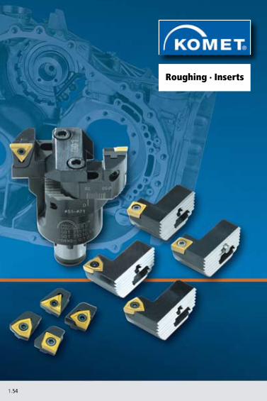
1.54
Roughing · Inserts

1.55
W01 ..
W29 ..
W29 .. 15
W29 .. 16
W83 .. W30 ..
W57 ..
W85 ..
E 1.63 E 1.63 E 1.66 E 1.68
E 1.64 E 1.65 E 1.67 E 1.69 E 1.70
E 1.20 E 1.20 E 1.14 E 1.88
E 1.74 E 1.74
E 1.59 E 1.60 E 1.59 E 1.58 E 1.58
1.56 – 1.571.621.711.721.73
Index Roughing
TwinKom® Twin Cutter• Construction • Machining options • Technical Notes• Problems – Possible causes – Solutions• Overhang length
Insert selection
Guideline values: cutting speed vc / feed f
Guideline values: higher cutting speed vc / insert coating
Chip formation
Optimum cutting depth range ap

1.56
Insert seating
TwinKom® G01 – ConstructionScale
Setting the diameter
Length adjustment screw Clamping screw
Length adjustment screw
Basic body
Holder
Clamping screw only required for twin cutter with axial adjustment
Insert seating
Adaptors with the same approach angle can be combined among each other
Adjusting pin Clamping plate
Clamping screw for clamping plate
Clamping screw for insert

1.57
d1d2
ap
d
D
fz
D
a p m
axd = 100 –100 – 80
2[( )+ 3]× 0,8
d = 89,6 mm
finishedof
fset
Example:Dfinished = 100 mmDblank = 80 mmOffset = 3 mm
Distribution of cut For burnt-out and pre-cast bores with large allowances.
d = Dfinished –Dfinished – Dblank
2[( )+ offset]× 0,8
With combination roughing and combination finishing, division of the whole cutting width is produced by offsetting the cutting edge axially and radially. This should allow the ensuing cutting forces to be better distributed and produce an even cutting result. With the roughing operation, this allows double the cutting width (using only a single feed rate f=fz). With the finishing operation, the cutting width is divided so that some of the intermediate machining can be omitted.
Combination roughing / Combination finishing
Length adjustmentLoosen insert seating and then tighten again slightly. Set length to 0.02 mm in front of required dimension using length adjustment screw , tighten insert seating and set to required height with length adjustment screw . Repeat the same procedure on the second side.
Setting the diameterLoosen the clamping screw on one side only. Set the diameter and tighten clam-ping screw again. Repeat the same procedure on the second side.
The scale is used purely for coarse setting the diameter. Exact diameter setting should be carried out with a setting device.
blan
k

1.58
0,20
0,15
0,10
0,05
1 2 30,5 1,5 2,5
W30 04120.02
W30 14120.04
W30 26120.05
0,20
0,15
0,10
0,05
1 2 3 4 5 6 7 8 9 10
W85 44000.34W85 32000.28W85 18000.20W85 18000.18
Cutting depth ap (mm)
Feed
f z (m
m/to
oth)
Cutting depth ap (mm)
Feed
f z (m
m/to
oth)
TwinKom® G01 – optimum cutting depth rangeGuideline values for medium strength steels
optimum range
optimum range

1.59
0,40
0,35
0,30
0,25
0,20
0,15
0,10
0,05
1 2 3 4 5 6 7 8 9 10 11
SOEX06
SOEX12
SOEX07
SOEX09
0,40
0,35
0,30
0,25
0,20
0,15
0,10
0,05
1 2 3 4 5 6 7 8 9 10 11
W29 10
W29 18
WOEX12W29 58 WOEX10
W29 50 WOEX08 W29 42
WOEX05W29 24
WOEX06W29 34
Guideline values for medium strength steels
Cutting depth ap (mm)
Feed
f z (m
m/to
oth)
Cutting depth ap (mm)
Feed
f z (m
m/to
oth)
optimum range
optimum range

1.60
0,40
0,35
0,30
0,25
0,20
0,15
0,10
0,05
0,5 1 1,5 2 2,5 3
W29 34160..
W29 24160..
W29 18160..
W29 10150..
W29 18150..
W29 34150..W29 24150..
W29 42150..
TwinKom® G01 – optimum cutting depth rangeGuideline values for geometry 15 and 16 for medium strength steels
Cutting depth ap (mm)
Feed
f z (m
m/to
oth)
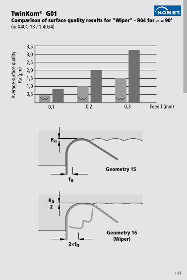
1.61
Ra2
2×fn
0,1 0,2 0,3
Ra
fn
3,5
3,0
2,5
2,0
1,5
1,0
0,5
TwinKom® G01Comparison of surface quality results for "Wiper" - R04 for = 90° (in X40Cr13 / 1.4034)
Aver
age
surfa
ce q
ualit
y Ra
(µm
)
Geometry 15
Geometry 16(Wiper)
Feed f (mm)
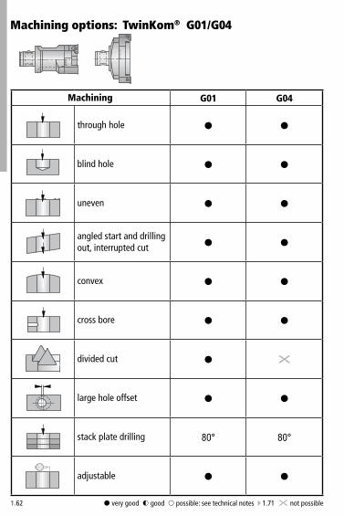
1.62
G01 G04
§ §
§ §
§ §
§ §
§ §
§ §
§ X
§ §
80° 80°
§ §
Machining options: TwinKom® G01/G04
§ very good $ good & possible: see technical notes E 1.71 X not possible
Machining
through hole
blind hole
uneven
angled start and drilling out, interrupted cut
convex
cross bore
divided cut
large hole offset
stack plate drilling
adjustable

1.63
W01 W29 .. 01 W29 .. 02 W29 .. 03 W29 .. 11 W29 .. 13 W29 .. 15 W29 .. 16
P BK84S BK77M BK7930K BK61N BK77H
P BK64 BK84 BK84 BK84S K10M BK79 BK73KN K10H
P BK72 BK64 BK6425 BK73 BK73S BK7710 BK73 BK73M BK72K CBN57/SK45 BK61N BK50H
P P40S K21 K10M P40K K10 K10N K21 K10H
P BK84SM BK73K BK60NH
Insert selection W01 / W29W
orkp
iece
m
ater
ial
Basic recommendation
alternative for better chip control
alternative for higher cutting speed E 1.20 - 1.21
PCD55
alternative for greater strength
for better surface finish

1.64
W29 .. 00 / .. 01 / .. 02 / .. 03 / .. 11 / .. 13
W29 10 ap= 1,5
W29 18 ap= 2,5
W29 24 ap= 4,5
W29 34 ap= 6
W29 42 ap= 7,5
W29 50 ap= 9
W29 58 ap= 9
P1.
0 200 0,10 0,12 0,15 0,20 0,25 0,30 0,30
2.0 200 0,10 0,12 0,15 0,20 0,25 0,30 0,30
2.1 180 0,10 0,12 0,15 0,20 0,25 0,30 0,30
3.0 140 0,10 0,12 0,15 0,20 0,25 0,30 0,30
4.0 120 0,06 0,10 0,12 0,15 0,20 0,25 0,25
4.1
S5.
0 50 0,06 0,08 0,10 0,12 0,15 0,18 0,20
5.1 50 0,06 0,08 0,10 0,12 0,15 0,18 0,20
M6.
0 120 0,07 0,09 0,12 0,12 0,15 0,20 0,20
6.1 120 0,07 0,09 0,12 0,12 0,15 0,20 0,20
7.0 90 0,05 0,07 0,10 0,10 0,12 0,15 0,15
K8.
0 180 0,12 0,15 0,25 0,25 0,30 0,35 0,35
8.1 140 0,12 0,15 0,25 0,25 0,30 0,35 0,35
9.0 140 0,12 0,15 0,25 0,25 0,30 0,35 0,35
9.1 120 0,10 0,12 0,15 0,20 0,25 0,30 0,35
10.0 100 0,10 0,12 0,15 0,20 0,25 0,30 0,35
10.1 100 0,10 0,12 0,15 0,20 0,25 0,30 0,35
10.2 90 0,12 0,15 0,25 0,30 0,30 0,35 0,35
N12
.0 250 0,12 0,15 0,25 0,25 0,30 0,35 0,35
12.1 250 0,12 0,15 0,25 0,25 0,30 0,35 0,35
13.0 250 0,12 0,15 0,25 0,25 0,30 0,35 0,35
13.1 250 0,12 0,15 0,25 0,25 0,30 0,35 0,35
14.0 200 0,12 0,15 0,25 0,25 0,30 0,35 0,35
H 15.0
16.0
Guideline values for roughing with TwinKom®
Important: For more application details and safety notes see E 1.37!
Mat
eria
l gro
up
Cutt
ing
spee
d v c
max. feed f (mm/tooth)

1.65
W29 .. 15 W29 .. 16
W29 10 ap= 1
W29 18 ap= 1,5
W29 24 ap= 2
W29 34 ap= 2
W29 42 ap= 2,5
P1.
0 200 0,06 0,10 0,18 0,18 0,25
2.0 200 0,06 0,10 0,18 0,18 0,25
2.1 180 0,06 0,10 0,18 0,18 0,25
3.0 140 0,06 0,10 0,18 0,18 0,25
4.0 120 0,06 0,10 0,18 0,18 0,25
4.1
S5.
05.
1
M6.
0 120 0,06 0,09 0,15 0,15 0,20
6.1 120 0,06 0,09 0,15 0,15 0,20
7.0 90 0,06 0,09 0,15 0,15 0,20
K8.
08.
19.
09.
110
.010
.110
.2
N12
.012
.113
.013
.114
.0
H 15.0
16.0
Mat
eria
l gro
up
Cutt
ing
spee
d v c
max. feed f (mm/tooth)

1.66
P BK84
SM BK79
K BK61
N BK84
H
P BK84 BK2730
S BK7710
M BK79 BK2730
KN BK7710
H
P BK69 / BK6115
SM BK74
K BK6115
N BK7710
H
PSMKNH
Insert selection W83W
orkp
iece
m
ater
ial
Geometry 01 Geometry 13 Geometry 21
Basic recommendation
alternative for better chip control
alternative for higher cutting speed E 1.14 - 1.15
alternative for greater strength

1.67
W83
W83 13ap= 1,5
W83 18ap= 2,5
W83 23 ap= 4,5
W83 32 ap= 4,5
W83 44ap= 7,5
P1.
0 200 0,12 0,14 0,20 0,25 0,35
2.0 200 0,12 0,14 0,20 0,25 0,35
2.1 180 0,12 0,14 0,20 0,25 0,35
3.0 140 0,12 0,14 0,20 0,25 0,35
4.0 120 0,10 0,12 0,18 0,25 0,3
4.1
S5.
0 50 0,08 0,10 0,15 0,20 0,25
5.1 50 0,08 0,10 0,15 0,20 0,25
M6.
0 120 0,10 0,12 0,18 0,25 0,30
6.1 120 0,10 0,12 0,18 0,25 0,30
7.0 90 0,10 0,12 0,18 0,25 0,30
K8.
0 180 0,15 0,20 0,25 0,35 0,50
8.1 140 0,15 0,20 0,25 0,35 0,50
9.0 140 0,15 0,20 0,25 0,35 0,50
9.1 120 0,15 0,20 0,25 0,35 0,50
10.0 100 0,12 0,15 0,20 0,25 0,40
10.1 100 0,12 0,15 0,20 0,25 0,40
10.2 90 0,15 0,20 0,25 0,30 0,40
N12
.0 250 0,15 0,20 0,25 0,35 0,50
12.1 250 0,15 0,20 0,25 0,35 0,50
13.0 250 0,15 0,20 0,25 0,35 0,50
13.1 250 0,15 0,20 0,25 0,35 0,50
14.0 200 0,15 0,20 0,25 0,35 0,50
H 15.0
16.0
Guideline values for roughing with TwinKom®
Important: For more application details and safety notes see E 1.37!
Mat
eria
l gro
up
Cutt
ing
spee
d v c
max. feed f (mm/tooth)

1.68
W30
P BK84
S K10
M BK84
K BK61
N K10
H
P CK32 / BK60
S K10
M CK32 / BK60
KN K10
H
P CK32 / BK60
S K10
M CK32 / BK60
K CBN57
N K10
H
P BK60
S K10
M BK60
K CBN57
N K10
H CBN40
Insert selection W30 / W57W
orkp
iece
m
ater
ial
W30 PCD / CBN W57 Geometry 12 W57 Geometry 14
Basic recommendation
alternative for better chip control
alternative for higher cutting speed E 1.88 - 1.90
PCD55
for better surface finish
PCD55

1.69
W30 / W57
W30 04 / W57 04ap= 0,15
W30 14 / W57 14ap= 0,4
W30 26 / W57 26ap= 0,6
P1.
0 200 0,07 0,10 0,15
2.0 200 0,06 0,12 0,20
2.1 180 0,07 0,12 0,25
3.0 140 0,06 0,10 0,20
4.0 120 0,05 0,10 0,15
4.1
S5.
0 50 0,04 0,08 0,10
5.1 50 0,04 0,08 0,10
M6.
0 120 0,05 0,10 0,15
6.1 120 0,05 0,10 0,15
7.0 90 0,04 0,08 0,15
K8.
0 180 0,10 0,15 0,30
8.1 140 0,10 0,15 0,30
9.0 140 0,08 0,15 0,25
9.1 120 0,08 0,15 0,25
10.0 100 0,08 0,15 0,25
10.1 100 0,07 0,12 0,25
10.2 90 0,10 0,15 0,25
N12
.0 250 0,04 0,08 0,20
12.1 250 0,08 0,15 0,20
13.0 250 0,06 0,10 0,15
13.1 250 0,08 0,12 0,20
14.0 200 0,08 0,12 0,20
H 15.0
16.0
Guideline values for roughing with TwinKom®
Important: For more application details and safety notes see E 1.37!
Mat
eria
l gro
up
Cutt
ing
spee
d v c
max. feed f (mm/tooth)

1.70
W85
W85 18ap= 1
W85 32ap= 1,5
W85 44ap= 2,5
P1.
0 200 0,08 0,10 0,15
2.0 200 0,08 0,10 0,15
2.1 180 0,08 0,10 0,15
3.0 140 0,08 0,08 0,12
4.0 120 0,07 0,08 0,10
4.1
S5.
05.
1
M6.
0 120 0,07 0,08 0,12
6.1 120 0,06 0,07 0,12
7.0 90 0,05 0,06 0,10
K8.
0 180 0,10 0,15 0,25
8.1 140 0,10 0,15 0,25
9.0 140 0,10 0,15 0,25
9.1 120 0,10 0,15 0,25
10.0 100 0,07 0,10 0,20
10.1 100 0,08 0,10 0,20
10.2 90 0,10 0,10 0,20
N12
.0 250 0,15 0,20 0,30
12.1 250 0,15 0,20 0,30
13.0 250 0,15 0,20 0,30
13.1 250 0,15 0,20 0,30
14.0 200 0,15 0,20 0,30
H 15.0
16.0
Guideline values for roughing with TwinKom®
Important: For more application details and safety notes see E 1.37!
Mat
eria
l gro
up
Cutt
ing
spee
d v c
max. feed f (mm/tooth)

1.71
for twin cutter TwinKom® Technical Notes
1. Starting on angled surfaces• subject to the starting angle, the feed must be reduced when star-
ting the bore. Rule of thumb: 3° 30%; 10° 40%; 25° 60% • use tough insert • use stable corner radius
3. Starting on cambered surfaces• no problems• reduce feed rate if necessary
4. Roughing through a cross bore• reduce feed rate 50% if necessary• watch for chip jamming around tool• use tough insert • use stable corner radius
2. Angled bore exit• from wear cut is interrupted reduce feed rate up to 50% • use tough insert • use stable corner radius
5. Starting on an edge• reduce feed rate by 50%• use tough insert • use stable corner radius
7. Roughing through stacked plates• use holder with 80° approach angle• good workpiece clamping required• max. gap = 1 mm
6. Starting on a welded seam• reduce feed rate• use max. 3×D tools

1.72
for twin cutter TwinKom® (possible cause > solution)
Problems – Possible causes – Solutions
Bad surface finish• feed rate too high > improve cutting parameters: increase cutting
speed, reduce feed• long chips > see table on page 1.74
Long chips• not optimum geometry> see table on page 1.74> select correct cutting depth> select correct cutting values
Vibrations• feed rate too high• cutting speed too high• geometry too obtuse • check axial / radial setting• check tool assembly

1.73
W01 ..06..W01 ..12..W01 ..20..
R0,4
R0,8
R0,4R0,8
R0,2R0,4
vc 100%
vc 60%
Selecting geometry for overhang
W29 ..13.. (Geometry 13)
W29 ..01.. (Geometry 01)
W29 ..02.. (Geometry 02)
Cutting speed in relation to overhang

1.74
W29 ..
ap = 2,5 mm ap = 2,5 mm ap = 2,5 mm ap = 2,5 mm ap = 2,5 mm
ap = 0,35 mm ap = 0,35 mm ap = 0,35 mm ap = 0,35 mm ap = 0,35 mm
apapapapap
Chip formation from various insert geometries
Tool: TwinKom® twin cutter G01 Ø 40 mmMaterial: 42CrMo4V 1100 N/mm²Cutting data: vc = 140 m/min f = 0,35 mm/rev
Geometry 01 Geometry 02 Geometry 03 Geometry 13 Geometry 15 / 16
Optimum cutting depth E 1.59
Optimum cutting depth E 1.60

1.75
Modules are the key!
The particular features of the innovative KOMET twin cutter programme are a high level of efficiency and flexibility. A large selection of different holders and inserts will solve every kind of application - even difficult machining tasks – with the right insert geometry.
Holder specifically for blind bore
Cartridge for SOEX insert

1.76
Fine Boring · Inserts
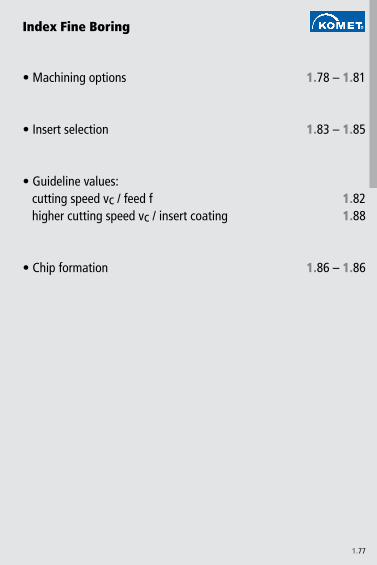
1.77
1.78 – 1.81
1.83 – 1.85
1.821.88
1.86 – 1.86
• Machining options
• Insert selection
• Guideline values:cutting speed vc / feed fhigher cutting speed vc / insert coating
• Chip formation
Index Fine Boring

1.78
UniTurn®
§ § §
§ § §
$ $ $
$ $ $
X X X
X X §
X X §
§ § §
Machining options
§ very good $ good & possible X not possible
MachiningBoring
barUniTurn®
with CBN
through hole
blind hole
angled start and drilling out, interrupted cut
cross bore
reverse machining
HRC > 54 through hole
HRC > 54 blind hole
vibration dampening

1.79
P1.
0 40-180 0,015 - 0,025 0,02 - 0,04
2.0 40-180 0,015 - 0,025 0,02 - 0,04
2.1 60-200 0,015 - 0,025 0,03 - 0,06
3.0 40-160 0,015 - 0,025 0,02 - 0,04
4.0 40-140 0,015 - 0,025 0,02 - 0,04
4.1
S5.
0 20-40 0,01 - 0,02 0,01 - 0,02
5.1 15-30 0,01 - 0,02 0,01 - 0,02
M6.
0 40-140 0,015 - 0,025 0,015 - 0,03
6.1 40-140 0,01 - 0,02 0,015 - 0,025
7.0 40-140 0,01 - 0,02 0,015 - 0,025
K8.
0 40-160 0,01 - 0,03 0,03 - 0,06
8.1 40-140 0,01 - 0,03 0,03 - 0,06
9.0 40-130 0,01 - 0,025 0,03 - 0,05
9.1 40-130 0,015 - 0,03 0,02 - 0,05
10.0 40-120 0,015 - 0,03 0,02 - 0,05
10.1 40-120 0,015 - 0,03 0,02 - 0,05
10.2 40-90 0,015 - 0,03 0,02 - 0,05
N12
.0 60-210 0,015 - 0,03 0,02 - 0,06
12.1 60-210 0,01 - 0,025 0,02 - 0,04
13.0 70-220 0,01 - 0,025 0,02 - 0,04
13.1 70-220 0,015 - 0,03 0,03 - 0,06
14.0 70-220 0,015 - 0,03 0,03 - 0,07
H 15.0 60-80 0,01-0,02 ap max 0,07
16.0 50-70 0,01-0,02 ap max 0,07
Important: For more application details and safety notes see E 1.37!
Guideline values for fine boringM
ater
ial g
roup
Cutt
ing
spee
d v c Boring bar UniTurn® UniTurn® with CBN
max. feed f (mm/rev) max. feed f (mm/rev) max. feed f (mm/rev)

1.80
§ §
§ §
$ $
$ $
X X
§ &
§ &
X §
Machining options:
§ very good $ good & possible X not possible
MachiningBoring
barLow-vibration
boring bar
through hole
blind hole
angled start and drilling out, interrupted cut
cross bore
reverse machining
HRC > 54 through hole
HRC > 54 blind hole
vibration dampening
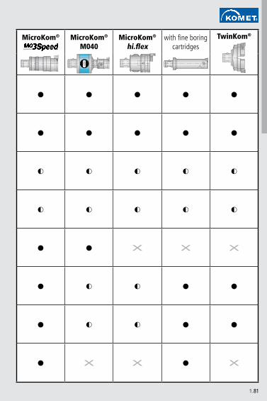
1.81
MicroKom® MicroKom®
M040MicroKom®
hi.flexTwinKom®
§ § § § §
§ § § § §
$ $ $ $ $
$ $ $ $ $
§ § X X X
§ $ $ § §
§ $ $ § §
§ X X § X
with fine boring cartridges

1.82
W00 04.. W30 04.. W30 14.. W30 26..W57 04.. W57 14.. W57 26..
P1.
0 300 0,04 0,07 0,10 0,15
2.0 250 0,04 0,06 0,12 0,20
2.1 300 0,04 0,07 0,12 0,25
3.0 200 0,03 0,06 0,10 0,20
4.0 180 0,03 0,05 0,10 0,15
4.1 80 0,02 0,04 0,08 0,12
S5.
0 60 0,01 0,04 0,08 0,10
5.1 80 0,01 0,04 0,08 0,10
M6.
0 180 0,01 0,05 0,10 0,15
6.1 160 0,01 0,05 0,10 0,15
7.0 160 0,01 0,04 0,08 0,15
K8.
0 200 0,05 0,10 0,15 0,30
8.1 160 0,05 0,10 0,15 0,30
9.0 180 0,04 0,08 0,15 0,25
9.1 160 0,04 0,08 0,15 0,25
10.0 140 0,04 0,08 0,15 0,25
10.1 140 0,03 0,07 0,12 0,25
10.2 120 0,03 0,10 0,15 0,25
N12
.0 300 0,02 0,04 0,08 0,20
12.1 400 0,05 0,08 0,15 0,20
13.0 500 0,02 0,06 0,10 0,15
13.1 350 0,05 0,08 0,12 0,20
14.0 300 0,05 0,08 0,12 0,20
H 15.0 120 0,05 0,08 0,10
16.0 90 0,05 0,08 0,10
Important: For more application details and safety notes see E 1.37!
Guideline values for fine boringM
ater
ial g
roup
Cutt
ing
spee
d v c
max. feed f (mm/rev)
max. feed f (mm/rev)
max. feed f (mm/rev)
max. feed f (mm/rev)
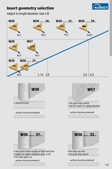
1.83
L / D
W30 ..... .31..
2,5 3,5 – 4,5
W30 W30 ..... .30..
R0,0
W30 ..... .32..
R0,2
W30 ..... .39..
R0,05R0,2
W30
R0,4
W57
R0,4
W30
R0,8
W30 ..... .31..
W30
W30 ..... .32..
W57
Insert geometry selectionsubject to length:diameter ratio L/D
• universal insert
surface structure produced
• for good chip control• for R.H. and L.H. cutting direction
surface structure produced
• very good surface quality at high feed rates• subject to stable conditions (max. 2×D)• for interrupted cut
• for large cut outs• for good chip control
surface structure produced surface structure produced

1.84
0,05
0,1
0,2
0,3
0,4
ap
W30 14... .31.. / W30 26... .31..UF
W30 ..120.32..US
W30 ..... .02..R0,2
W30 ..120.30..R0,0 W30 ..820.32..
US
W30 ..... .39..
W57 ..140. ....R0,2R0,4
W57 ..040. ....R0,4
W30 26... .08..R0,8
W30 14... .08..R0,8
W30 14... .04.. / W30 26... .04..R0,4
subject to cutting depth ap in the radius – machining steel
Insert geometry selection

1.85
0,15
0,25
0,75
1,5
2,0
ap
W57 14120. ..23W57 26120. ..23 W30 04990. ..55
W57 04120.0223
0,5
1,0W58 13120. ..23W58 18120. ..23W58 23120. ..23
2,5
3,0
3,5
4,0
W32 23150.04..W32 32150.04..
W32 03990.0455
W32 13150.04..W32 18150.04..
W58 03120.0423
W32 03150.04..
W32 ..940. ..
W32 ..600. ..
W37 ..600. ..
W30 18990. 0455W30 23990. 0455W30 32990. 0455
W30 14990. ..55W30 26990. ..55
W32 13990.0455
W32 44150.08..
Insert geometry selectionsubject to cutting depth ap in the radius – machining aluminium
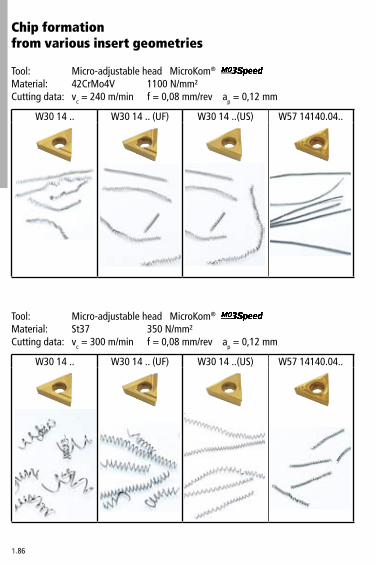
1.86
W30 14 .. W30 14 .. (UF) W30 14 ..(US) W57 14140.04..
W30 14 .. W30 14 .. (UF) W30 14 ..(US) W57 14140.04..
Chip formation from various insert geometries
Tool: Micro-adjustable head MicroKom® Material: 42CrMo4V 1100 N/mm²Cutting data: vc = 240 m/min f = 0,08 mm/rev ap = 0,12 mm
Tool: Micro-adjustable head MicroKom® Material: St37 350 N/mm²Cutting data: vc = 300 m/min f = 0,08 mm/rev ap = 0,12 mm

1.87
W30 14 .. W30 14 .. (UF) W30 14 ..(US) W57 14140.04..
Tool: Micro-adjustable head MicroKom® Material: X10CrNiMoTi18 750 N/mm²Cutting data: vc = 160 m/min f = 0,08 mm/rev ap = 0,12 mm

1.88
P M K NP25M P40 BK60 BK6110 BK64 BK2710 BK84 CK30 CK32 CK37 CK38 CBN40 P25M P40 BK2710 BK84 CK30 CK32 CK37 CK38 K10 BK61 BK6110 BK2710 CBN57 K10 PKD55
40 > 52HRC 4050 5060 6070 7080 8090 90
100 100110 110120 120130 130140 140150 150160 160170 170180 180190 190200 200210 210220 220230 230240 240250 250260 260270 270280 280290 290300 300310 310320 320330 330340 340350 350360 360370 370380 380390 390400 400410 410420 420430 430440 440450 450460 460470 470480 480490 490500 500600 600700 700800 800900 9001000 10001100 1100
Cutting speedvc (m/min)
Important: For more application details and safety notes see E 1.37!
Guideline values for fine boring: W30
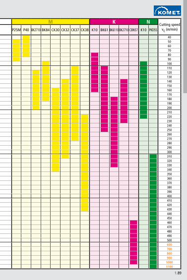
1.89
P M K NP25M P40 BK60 BK6110 BK64 BK2710 BK84 CK30 CK32 CK37 CK38 CBN40 P25M P40 BK2710 BK84 CK30 CK32 CK37 CK38 K10 BK61 BK6110 BK2710 CBN57 K10 PKD55
40 > 52HRC 4050 5060 6070 7080 8090 90
100 100110 110120 120130 130140 140150 150160 160170 170180 180190 190200 200210 210220 220230 230240 240250 250260 260270 270280 280290 290300 300310 310320 320330 330340 340350 350360 360370 370380 380390 390400 400410 410420 420430 430440 440450 450460 460470 470480 480490 490500 500600 600700 700800 800900 900
1000 10001100 1100
Cutting speedvc (m/min)

1.90
P M K NBK84 BK60 CK32 BK84 CK32 BK60 K10(23) BK7710
405060708090
100110120130140150160170180190200210220230240250260270280290300310320330340350360370380390400410420430440450460470480490500600700800900
10001100
Cutting speedvc (m/min)
Important: For more application details and safety notes see E 1.37!
Guideline values for fine boring: W57..14

1.91
E F T
6°
12°
20°
MKNSH
P
MKNSH
P
MK
P
NSH
MKNSH
P
MKNSH
P
MP
KNSH
MK
P
NS
N
MK
SH
PM
NS
P
MKNSH
PMKNSH
P
MK
H
P
NS
H
K
H
Guidelines for selecting inserts
Selecting the top rakeRecommendations for using inserts with ground chip grooves(W00, W01, W04, W30, W32, W34, W37, W60)
rounded sharp-edged chamfered
PCD55PCD5520

1.92
W 6 0 3 2 0 6 0 . 0 8 6 0W 2 9 2 4 0 1 0 . 0 4 0 3
03 = 3,97 mm04 = 4,0 mm10 = 5,0 mm12 = 5,5 mm13 = 5,56 mm14 = 5,6 mm17 = 6,0 mm18 = 6,35 mm20 = 7,0 mm22 = 7,7 mm
23 = 7,94 mm24 = 8,0 mm26 = 8,2 mm32 = 9,52 mm34 = 10,0 mm42 = 12,0 mm44 = 12,7 mm50 = 15,0 mm58 = 17,6 mm
01 = P1003 = P25M...
W 8 3 1 3 0 0 0 . 0 1 6 1
Numerical Coding for Inserts W..
Standard inserts
00 = Unisix standard, chip groove ground 01 = Unisix strengthened, chip groove ground 04 = Unisix, 6 edged, chip groove ground 05 = Unisix, 6 edged, chip groove ground 24 = Unisix strengthened, chip groove sintered 25 = Unisix standard, chip groove sintered 27 = Unisix strengthened, chip groove sintered 28 = Unisix standard, chip groove sintered 29 = Unisix strengthened, chip groove sintered
30 = U.., chip groove ground 32 = TPH.., chip groove ground 34 = T.., chip groove ground 36 = U.., 6 edged, chip groove ground 37 = TEH.., chip groove ground 57 = U..., chip groove sintered 58 = TP..., chip groove sintered 59 = T..., chip groove sintered
60 = C.., chip groove ground 78 = Copying insert 35°, chip groove sintered 79 = C.., chip groove sintered
Insert geometry Inscribed circle d1
Material gradep.ex.
Numerical Coding for Inserts W83 - W89
Standard inserts
83 = S... square84 = T... triangular
85 = C... rhomboid 80° 86 = D... rhomboid 55° 89 = V... rhomboid 35°
Insert geometry ISO basic forms
90 = W... hexagonal 80° 95 = R... round 97 = threaded

1.93
01 = R 0,1 mm 02 = R 0,2 mm 03 = R 0,3 mm 04 = R 0,4 mm 05 = R 0,5 mm 06 = R 0,6 mm 08 = R 0,8 mm 12 = R 1,2 mm
30 = U8.00 R 0
31 = UF 32 = US
13 = 5,56 mm18 = 6,35 mm24 = 8,0 mm32 = 9,52 mm38 = 11,1 mm44 = 12,7 mm53 = 15,88 mm62 = 19,05 mm
00 ... 99
1 ... 9
01 ... 99
01 = P1003 = P25M...
Inscribed circle d1
Serial number
Modification code
Serial number
Material gradep.ex.
Type of chip groove / chip surface
sintered00 = double chip groove (PD) cutting edge rounded01 = double chip groove (K) cutting edge chamfered and rounded02 = step geometry (KS) cutting edge chamfered and rounded03 = dimple geometry (KX) cutting edge rounded04 = finished geometry05 = 10° chip groove (T) cutting edge rounded06 = 12° chip groove (C) cutting edge rounded07 = finished geometry10 = shank geometry, cutting edge chamfered and rounded11 = 20° chip groove, cutting edge rounded12 = Al / finished geometry13 = shank geometry, cutting edge rounded14 = finishing topography15 = semi-finishing topography16 = semi-finishing topography with wiper edge17 = 22° topography/ tangential insert21 = 20° highly positive/ „Technology 21“
ground00 = L.H. cutting, neutral06 = L.H. cutting, 6°12 = L.H. cutting, 12°15 = L.H. cutting, 15°18 = L.H. cutting, 18°20 = L.H. cutting, 20°30 = R.H. cutting, neutral36 = R.H. cutting, 6°42 = R.H. cutting, 12°45 = R.H. cutting, 15°48 = R.H. cutting, 18°50 = R.H. cutting, 20°60 = neutral66 = 3x ground, 6°70 = 3x ground, 10°72 = 3x ground, 12°80 = 3x ground, 20°82 = L.H. cutting, 12° sharp-edged83 = R.H. cutting, 12° sharp-edged94 = neutral, bright complete, NL/NR98 = neutral, bright on corner99 = neutral, bright on corner, NL/NR
Geometry of cutting edge
33 = U8.77 15° clearance angle, additional, cutting edge form for Unisix milling cutter inserts34 = F and KUF 90° 35 = F and KUF 75° 36 = F and KUF 60° 39 = R 0,05 mm 40 = 45° corner for chamfering cartridge 75 = Support chamfer 75° L.H.90 = Support chamfer 90° L.H.
Modification code 1 ... 9

1.94
Q 0 9 1 8 0 0 0 . 1 7 0 6
13 = 5,56 mm18 = 6,35 mm24 = 8,0 mm32 = 9,52 mm38 = 11,1 mm44 = 12,7 mm53 = 15,88 mm
01 ... 99
1 ... 9
01 ... 99
01 = P1003 = P25M...
Numerical Coding for Inserts Q...
Standard inserts
09 = S... square12 = T... triangular15 = C... rhomboid 80°21 = E... rhomboid 75°36 = A... rhomboid form
Insert geometry ISO basic forms
Inscribed circle d1
Serial number
Modification code
Serial number
Material gradep.ex.
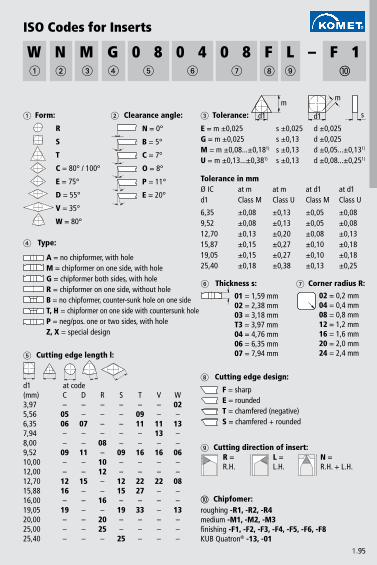
1.95
W N M G 0 8 0 4 0 8 F L – F 1
01 = 1,59 mm02 = 2,38 mm03 = 3,18 mmT3 = 3,97 mm04 = 4,76 mm06 = 6,35 mm07 = 7,94 mm
R
S
T
C = 80° / 100°
E = 75°
D = 55°
V = 35°
W = 80°
N = 0°
B = 5°
C = 7°
O = 8°
P = 11°
E = 20°
E = m ±0,025 s ±0,025 d ±0,025G = m ±0,025 s ±0,13 d ±0,025M = m ±0,08...±0,181) s ±0,13 d ±0,05...±0,131)
U = m ±0,13...±0,381) s ±0,13 d ±0,08...±0,251)
s
mm
d1 d1
6,35 ±0,08 ±0,13 ±0,05 ±0,089,52 ±0,08 ±0,13 ±0,05 ±0,0812,70 ±0,13 ±0,20 ±0,08 ±0,1315,87 ±0,15 ±0,27 ±0,10 ±0,1819,05 ±0,15 ±0,27 ±0,10 ±0,1825,40 ±0,18 ±0,38 ±0,13 ±0,25
02 = 0,2 mm04 = 0,4 mm08 = 0,8 mm12 = 1,2 mm16 = 1,6 mm20 = 2,0 mm24 = 2,4 mm
d1(mm) C D R S T V W3,97 – – – – – – 025,56 05 – – – 09 – –6,35 06 07 – – 11 11 137,94 – – – – – 13 –8,00 – – 08 – – – –9,52 09 11 – 09 16 16 0610,00 – – 10 – – – –12,00 – – 12 – – – –12,70 12 15 – 12 22 22 0815,88 16 – – 15 27 – –16,00 – – 16 – – – –19,05 19 – – 19 33 – 1320,00 – – 20 – – – –25,00 – – 25 – – – –25,40 – – – 25 – – –
ISO Codes for Inserts
Form:
Thickness s:
Clearance angle: Tolerance:
Tolerance in mmØ IC at m at m at d1 at d1d1 Class M Class U Class M Class U
Corner radius R:
roughing -R1, -R2, -R4medium -M1, -M2, -M3finishing -F1, -F2, -F3, -F4, -F5, -F6, -F8KUB Quatron® -13, -01
Cutting edge length l:
Type:
A = no chipformer, with holeM = chipformer on one side, with holeG = chipformer both sides, with holeR = chipformer on one side, without holeB = no chipformer, counter-sunk hole on one sideT, H = chipformer on one side with countersunk holeP = neg/pos. one or two sides, with holeZ, X = special design
at codeCutting edge design:
F = sharpE = roundedT = chamfered (negative)S = chamfered + rounded
Cutting direction of insert:R = R.H.
Chipfomer:
L = L.H.
N = R.H. + L.H.

1.96
Types of wear on inserts
Wear on clearance facenormal type of wear expectedremedy:• use hardened/wear-resistant cutting materials• reduce cutting parameters
Pitting caused by:• coating/substrate not sufficiently wear-resistant• chip geometry too negativerectified by:• substrate or coatings with better wear resistance• positive chip geometries
Stress fracture caused by:• wrong/excessively high cutting parameters• no allowance for tool restrictions • interrupted cutrectified by:• checking of cutting data• checking of tool restrictions
Thermal wear caused by:• cutting speed too high• excessive heatrectified by:• reduction of cutting speed• wear-resistant, more thermally stable coatings or substrate
Microscopic fracturing caused by:• coating/substrate too brittle• vibrations on part or tool• interrupted cut• build-up on cutting edgescorrecting by:• tougher coating• avoidance of vibrations• avoidance of build-up on cutting edges

1.97
Fracture of centre insertcaused by:• basic substrate/coatings too brittle• central position of internal insert too high (insert
protrudes over centre)rectified by:• tougher coatings and substrate• check lower central position of internal insert• use centre plate with stronger chamfering• use internal and external insert with same geometry
Plastic deformation of KUB Quatron® cutting edge
• cutting material too soft• replace insert with more wear-resistant type

2.�
Thread milling / Drill thread milling
Tapping
Roll form tapping
Drilling with solid carbide drills
Drilling/milling with PCD tools
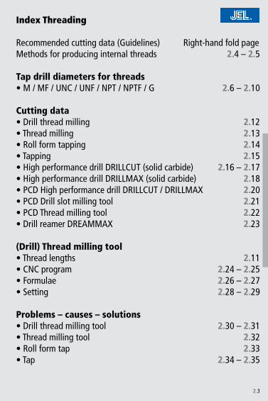
2.�
2.4 – 2.5
2.6 – 2.10
2.1�2.1�
2.142.15
2.16 – 2.172.182.�02.�12.��2.��
2.112.�4 – 2.�52.�6 – 2.�72.�8 – 2.�9
2.�0 – 2.�1
2.��2.��
2.�4 – 2.�5
Index Threading
Recommended cutting data (Guidelines) Right-hand fold pageMethods for producing internal threads
Tap drill diameters for threads • M / MF / UNC / UNF / NPT / NPTF / G
Cutting data • Drill thread milling• Thread milling• Roll form tapping• Tapping• High performance drill DRILLCUT (solid carbide) • High performance drill DRILLMAX (solid carbide) • PCD High performance drill DRILLCUT / DRILLMAX• PCD Drill slot milling tool• PCD Thread milling tool• Drill reamer DREAMMAX
(Drill) Thread milling tool• Thread lengths • CNC program • Formulae• Setting
Problems – causes – solutions • Drill thread milling tool• Thread milling tool• Roll form tap • Tap

2.4
Thread milling
Methods for producing internal threads
• Chip producing method• Thread making by helical interpolation within the
pitch• Same tool can be used for all threads with the
same pitch starting from the nominal Ø • Same tool can be used for different materials up to
45 HRC• Lower torque than with tapping and roll form
tapping• Drill depth = thread depth if tool is not used for
chamfering • Machine spindle always running in the same
direction – no reversing necessary• High speed cutting (HSC) possible
Drill thread milling
• Chip producing method• Complete thread is manufactured in a single pass
– drilling, chamfering and thread milling • One tool per dimension which can also be used
for different materials• Prerequisite: CNC machine or machining centre
being capable to run helical interpolation
Drill thread milling: machining sequence

2.5
• Chip producing method• Thread making by rotation – pitch is on the tool• Can be used on almost all machines• 1 tool per dimension required
Tapping
Through holeJEL tap Type: Dorex
Blind holeJEL tap Type: Sirex SR
Blind and through holeShort chipping materialsJEL tap Type: GG
• Chip less method• Thread making by forming – pitch is on the tool• Suitable for materials with elongation of >5% and tensile strength of <1000N/mm�
• Tap drill Ø larger than with tapping• Higher torque than tapping• Generates forming gap at minor diameter
Thread forming – grain structure
Roll form tapping
forming gap

2.6
M
M 2 � 0,40 1,60 � 0,40 1,80
M 2,2 �,� 0,45 1,75 �,� 0,45 1,98
M 2,5 �,5 0,45 �,05 �,5 0,45 �,�8
M 3 � 0,50 �,50 � 0,50 �,75
M 3,5 �,5 0,60 �,90 �,5 0,60 �,�0
M 4 4 0,70 �,�0 4 0,70 �,65
M 4,5 4,5 0,75 �,70 4,5 0,75 4,1�
M 5 5 0,80 4,�0 5 0,80 4,60
M 6 6 1,00 5,00 6 1,00 5,50
M 7 7 1,00 6,00 7 1,00 6,50
M 8 8 1,�5 6,80 8 1,�5 7,�8
M 9 9 1,�5 7,80 9 1,�5 8,�8
M10 10 1,50 8,50 10 1,50 9,�5
M11 11 1,50 9,50 11 1,50 10,�5
M12 1� 1,75 10,�0 1� 1,75 11,1�
M14 14 �,00 1�,00 14 �,00 1�,00
M16 16 �,00 14,00 16 �,00 15,00
M18 18 �,50 15,50 – – –
M20 �0 �,50 17,50 – – –
Tap drill diameters for threads
Nom. Ø Pitch Core Ø
Note for formed threads: The core diameters listed are guidelines. The actual core diameters have to be investigated in use as these depend on the fluidity of the material and the forming speed.
Nom. Ø Pitch Core Ø
Metric Thread
milled and cut threads formed threads
Size

2.7
MF
M4×0,5 4 0,50 �,50 4 0,50 �,75M5×0,5 5 0,50 4,50 5 0,50 4,75M6×0,5 6 0,50 5,50 6 0,50 5,75M6×0,75 6 0,75 5,�0 6 0,75 5,6�M8×0,5 8 0,50 7,50 8 0,50 7,75M8×0,75 8 0,75 7,�0 8 0,75 7,6�
M8×1 8 1,00 7,00 8 1,00 7,50M10×0,75 10 0,75 9,�0 10 0,75 9,6�
M10×1 10 1,00 9,00 10 1,00 9,50M12×1 1� 1,00 11,00 1� 1,00 11,50
M12×1,5 1� 1,50 10,50 1� 1,50 11,�5M14×1 14 1,00 1�,00 14 1,00 1�,50
M14×1,5 14 1,50 1�,50 14 1,50 1�,�5M15×1,5 15 1,50 1�,50 15 1,50 14,�5M16×1 16 1,00 15,00 16 1,00 15,50
M16×1,5 16 1,50 14,50 16 1,50 15,�5M17×1,5 17 1,50 15,50 17 1,50 16,�5M18×1 18 1,00 17,00 18 1,00 17,50
M18x1,5 18 1,50 16,50 18 1,50 17,�5M18×2 18 �,00 16,00 18 �,00 17,00M20×1 �0 1,00 19,00 �0 1,00 19,50
M20×1,5 �0 1,50 18,50 �0 1,50 19,�5M20×2 �0 �,00 18,00 �0 �,00 19,00M22×1 �� 1,00 �1,00 �� 1,00 �1,50
M22×1,5 �� 1,50 �0,50 �� 1,50 �1,�5M22×2 �� �,00 �0,00 �� �,00 �1,00M24×1 �4 1,00 ��,00 �4 1,00 ��,50
M24×1,5 �4 1,50 ��,50 �4 1,50 ��,�5M24×2 �4 �,00 ��,00 �4 �,00 ��,00
M30×1,5 �0 1,50 �8,50 �0 1,50 �9,�5
Nom. Ø Pitch Core Ø Nom. Ø Pitch Core Ø
Metric Fine Thread
milled and cut threads formed threads
Size

2.8
UNC
Nr. 10 4,8�0 �4 �,90 4,8�0 �4 4,�9
Nr. 12 5,486 �4 4,50 5,486 �4 4,96
1/4 6,�50 �0 5,10 6,�50 �0 5,7�
5/16 7,9�8 18 6,60 7,9�8 18 7,��
3/8 9,5�5 16 8,00 9,5�5 16 8,7�
7/16 11,11� 14 9,40 11,11� 14 10,�0
1/2 1�,700 1� 10,80 1�,700 1� 11,7�
9/16 14,�88 1� 1�,�0 14,�88 1� 1�,��
5/8 15,875 11 1�,50 – – –
UNF
Nr. 10 4,8�6 �� 4,05 4,8�6 �� 4,4�
Nr. 12 5,486 �8 4,60 5,486 �8 5,0�
1/4 6,�50 �8 5,45 6,�50 �8 5,90
5/16 7,9�8 �4 6,90 7,9�8 �4 7,41
3/8 9,5�5 �4 8,45 9,5�5 �4 9,00
7/16 11,11� �0 9,85 11,11� �0 10,48
1/2 1�,700 �0 11,45 1�,700 �0 1�,07
9/16 14,�88 18 1�,90 14,�88 18 1�,58
5/8 15,875 18 14,45 15,875 18 15,17
Note for formed threads: The core diameters listed are guidelines. The actual core diameters have to be investigated in use as these depend on the fluidity of the
material and the forming speed.
Nom. Ø Pitch t.p.i. Core Ø Nom. Ø Pitch t.p.i. Core Ø
American Unified Fine Thread
milled and cut threads formed threads
Size
Tap drill diameters for threads
Nom. Ø Pitch t.p.i. Core Ø Nom. Ø Pitch t.p.i. Core Ø
American Unified Coarse Thread
milled and cut threads formed threads
Size

2.9
NPTNPTF
1/16 �7 6,15 6,10
1/8 �7 8,50 8,45
1/4 18 11,00 10,90
3/8 18 14,50 14,�0
1/2 14 17,85 17,60
3/4 14 ��,�0 ��,00
1“ 11 1/� �9,00 �8,75
1 1/4“ 11 1/� �7,80 �7,50
1 1/2“ 11 1/� 44,00 4�,75
2“ 11 1/� 56,00 55,75
D1
Pitch t.p.i. Core Ø D1NPT
Core Ø D1NPTF
Size
without using a reamer
milled and cut threads

2.10
G
G 1/8“ 9,7�8 �8 8,90
G 1/4“ 1�,157 19 11,70
G 3/8“ 16,66� 19 15,40
G 1/2“ �0,955 14 19,10
G 5/8“ ��,911 14 �1,10
G 3/4“ �6,441 14 �4,60
G 7/8“ �0,�01 14 �8,40
G 1“ ��,�49 11 �0,80
G 1 1/8“ �7,897 11 �5,50
G 1 1/4“ 41,910 11 �9,50
G 1 3/8“ 44,��� 11 41,90
G 1 1/2“ 47,80� 11 45,40
G 1 3/4“ 5�,746 11 51,40
G 2“ 59,614 11 57,�0
Pipe Thread DIN EN ISO 228
milled and cut threads
Tap drill diameters for threads
Nom. Ø Pitch t.p.i. Core ØSize

2.11
�,5×
D
�,0×
D
�,5×
D
�,5×
D
�,5×
D
�,0×
D
�,0×
D
�,0×
D
�,0×
D
1,5×
D
1,5×
D
�,0×
D
�,0×
D
�,0×
D
�,0×
D
�,0×
D
�,5×
D
�,5×
D
1,5×
D
1,5×
D
�,5×
D
�,5×
D
�,5×
D
Stee
l
Stai
nles
s st
eel
Gre
y ca
st ir
on
Nod
ular
gre
y ca
st ir
on
Tita
nium
allo
ys
Nic
kel a
lloys
Copp
er a
lloys
Alum
iniu
m
Plas
tics
(Drill) Thread milling tool
achievable thread lengths
Advantage with drill thread milling:• only 1 tool for drilling, countersinking and thread milling
Advantages with thread milling:• one and the same tool for blind bore and through hole• one and the same tool for different diameters > nominal Ø with the same pitch• one and the same tool for different tolerances• one and the same tool for different materials
Drill thread milling BGF
Thread milling MKG
Thread milling MGF

2.1�
TiAlN TiAlN TiAlN
# 6mm # 1�mm # 6mm # 1�mm
vc (m/min) vc (m/min) vc (m/min)
P1.
1 100-150 0,0�-0,10
1.� 100-150 0,0�-0,10
1.� 100-150 0,0�-0,10
1.4 100-150 0,0�-0,10
1.5 100-150 0,0�-0,10
1.6 100-150 0,0�-0,10
H 1.7
1.8
M�.
1�.
��.
�
K�.
1 50-80 80-1�0 0,10-0,15 0,15-0,�� 0,0�-0,05 0,05-0,10 100-�00 0,05-0,15
�.� 50-80 80-1�0 0,10-0,15 0,15-0,�� 0,0�-0,05 0,05-0,10 100-�00 0,05-0,15
�.� 50-80 80-1�0 0,10-0,15 0,15-0,�� 0,0�-0,05 0,05-0,10 100-�00 0,05-0,15
�.4 100-�00 0,05-0,15
�.5 100-�00 0,05-0,15
�.6 100-�00 0,05-0,15
S4.
14.
�4.
�5.
15.
�5.
�
N6.
16.
� 100-�00 0,10-0�0 0,06-0,10 0,0�-0,06 0,06-0,10 100-�00 0,05-0,15
6.� 100-�00 0,05-0,15
6.4
7.1 100-400 100-400 0,10-0,�5 0,�5-0,�0 0,0�-0,06 0,06-0,10 100-400 0,05-0,�0
7.� 100-400 100-400 0,10-0,�5 0,�5-0,�0 0,0�-0,06 0,06-0,10 100-400 0,05-0,�0
7.� 100-400 100-400 0,0�-0,06 0,06-0,1� 0,0�-0,06 0,06-0,10 100-400 0,05-0,�0
7.4 100-�00 100-400 0,10-0,�5 0,�5-0,�0 0,0�-0,06 0,06-0,10 100-400 0,05-0,�0
7.5 100-�00 0,10-0,�5 0,�5-0,�0 0,0�-0,06 0,06-0,10 100-�00 0,05-0,�0
8.1 60-1�0 60-1�0 0,10-0,�5 0,�5-0,�0 0,0�-0,06 0,06-0,10 100-�00 0,05-0,�0
8.� 60-100 60-100 0,10-0,�5 0,�5-0,�0 0,0�-0,06 0,06-0,10 100-�00 0,05-0,�0
8.� 40-60 60-80 0,10-0,15 0,15-0,�� 0,0�-0,05 0,05-0,10 100-150 0,05-0,�0
Drill thread milling
Surface uncoated
Nom. Ø
Material fb (mm/rev) fb (mm/rev) fz (mm/tooth) fz (mm/tooth) fz (mm/tooth)

2.1�
TiAlN TiAlN TiAlN
# 6mm # 1�mm
vc (m/min) vc (m/min) vc (m/min)
P1.
1 80-150 0,015-0,040 0,040-0,060 0,08-0,15 0,08-0,15
1.� 80-100 0,015-0,040 0,040-0,060 0,08-0,15 0,08-0,15
1.� 80-100 0,015-0,040 0,040-0,060 0,08-0,15 0,08-0,15
1.4 80-100 0,015-0,040 0,040-0,060 0,08-0,15 0,08-0,15
1.5 60-80 0,010-0,0�0 0,040-0,060 0,04-0,10 0,04-0,10
1.6 50-60 0,010-0,0�5 0,0�0-0,050 0,04-0,10 0,04-0,10
H 1.7 �0-50 0,010-0,015 0,015-0,0�0 0,0�-0,08 0,0�-0,08
1.8 �0-40 0,010-0,015 0,015-0,0�0
M�.
1 60-80 0,015-0,0�0 0,0�0-0,050 0,08-0,15 0,08-0,15
�.� 60-80 0,015-0,0�0 0,0�0-0,050 0,04-0,10 0,04-0,10
�.� 60-80 0,010-0,0�5 0,0�0-0,040 0,04-0,10 0,04-0,10
K�.
1 50-80 80-1�0 0,0�0-0,040 0,040-0,100 0,08-0,15 0,08-0,15
�.� 50-80 80-1�0 0,0�0-0,0�0 0,040-0,080 0,08-0,1� 0,08-0,1�
�.� 80-1�0 0,0�0-0,040 0,040-0,100 0,08-0,15 0,08-0,15
�.4 80-100 0,0�0-0,0�0 0,040-0,080 0,08-0,1� 0,08-0,1�
�.5 80-100 0,0�0-0,040 0,040-0,100 0,08-0,15 0,08-0,15
�.6 80-100 0,0�0-0,0�0 0,040-0,080 0,08-0,1� 0,08-0,1�
S4.
1 40-100 0,015-0,0�0 0,0�0-0,080 0,08-0,15 0,08-0,15
4.� 40-100 0,015-0,0�0 0,0�0-0,080 0,08-0,15 0,08-0,15
4.� 40-80 0,015-0,0�0 0,0�0-0,060 0,08-0,1� 0,08-0,1�
5.1 50-60 0,0�0-0,040 0,040-0,060 0,04-0,10 0,04-0,10
5.� �0-40 0,0�0-0,040 0,040-0,060 0,04-0,10 0,04-0,10
5.� 10-�0 0,015-0,0�0 0,0�0-0,050 0,04-0,08 0,04-0,08
N6.
1 100-�00 100-400 0,040-0,070 0,070-0,1�0 0,10-0,�0 0,10-0,�0
6.� 100-�00 100-400 0,040-0,070 0,070-0,1�0 0,10-0,�0 0,10-0,�0
6.� 100-�00 100-400 0,040-0,070 0,070-0,1�0 0,10-0,�0 0,10-0,�0
6.4 60-80 60-80 0,0�0-0,040 0,0�0-0,060 0,08-0,15 0,08-0,15
7.1 100-400 100-400 0,0�0-0,070 0,070-0,1�0 0,10-0,�0 0,10-0,�0
7.� 100-400 100-400 0,0�0-0,070 0,070-0,1�0 0,10-0,�0 0,10-0,�0
7.� 100-400 100-400 0,0�0-0,070 0,070-0,1�0 0,10-0,�0 0,10-0,�0
7.4 100-�00 100-400 0,0�0-0,070 0,070-0,1�0 0,10-0,�0 0,10-0,�0
7.5 100-�00 100-�50 0,0�0-0,070 0,070-0,1�0 0,10-0,�0 0,10-0,�0
8.1 80-100 100-1�0 0,040-0,060 0,060-0,1�0 0,08-0,�0 0,08-0,�0
8.� 80-100 100-1�0 0,040-0,060 0,060-0,1�0 0,08-0,15 0,08-0,15
8.� 50-60 60-80 0,040-0,060 0,060-0,1�0 0,08-0,15 0,08-0,15
Thread milling
Surface uncoated
Nom. Ø
Material fb (mm/rev) fb (mm/rev) fz (mm/tooth)

2.14
HSS HSS
vc (m/min) vc (m/min) vc (m/min) vc (m/min)
P1.
1 �0-40 �0-50 �0-80 E/O
1.� �5-�5 �0-50 �0-80 E/O
1.� �0-�0 �0-50 �0-80 E/O
1.4 �0-�5 �0-�0 �0-50 O
1.5 �0-�0 �0-50 O
1.6
H 1.7
1.8
M�.
1 �0-40 �0-50 O
�.� �0-�0 �0-40 O
�.� �0-�0 �0-40 O
K�.
1�.
��.
� �0-40 �0-60 E/O
�.4 �0-�0 �0-40 E/O
�.5
�.6
S4.
1 10-15 �0-�0 O
4.� 8-1� �0-�5
4.� 5-10 10-15
5.1 10-15 15-�0 10-�0 O
5.� 5-10 10-15 10-�0 O
5.� 5-10 O
N6.
1 �0-�0 �0-50 �0-60 �0-80 O/E
6.�
6.� �0-�0 �0-50 �0-60 �0-80 O/E
6.4
7.1 �0-50 �0-60 �0-80 O/E
7.� �0-50 �0-60 �0-80 O/E
7.� �0-50 �0-60 �0-80 O/E
7.4 �0-50 �0-60 �0-80 O/E
7.5 �0-50 �0-60 �0-80 O/E
8.1
8.�
8.�
Thread forming
1) HSS-E with carbide strips
CoolantE = EmulsionO = OilT= DryL = Air
Surface nitrided coated uncoated coated
Cut. material Solid carbide / HML 1) Solid carbide / HML 1)
Material

2.15
HSS HSS
vc (m/min) vc (m/min) vc (m/min) vc (m/min)
P1.
1 15-�0 �0-50 E/O
1.� 15-�5 �0-40 E/O
1.� 15-�0 �0-�5 E/O
1.4 10-15 �0-�0 E/O
1.5 5-10 15-�0 O/E
1.6 �-5 10-15 O
H 1.7 �-8 O
1.8 �-5 O
M�.
1 5-10 10-�5 O
�.� 4-8 10-�0 O
�.� �-5 7-1� O
K�.
1 10-�0 �0-�5 �0-50 E/T
�.� 5-10 15-�0 �0-50 E
�.� 10-�0 �0-40 �0-50 E
�.4 5-10 10-15 �0-50 E/O
�.5 10-15 �0-40 �0-50 E/O
�.6 5-10 10-�0 �0-50 E/O
S4.
1 5-15 10-15 E/O
4.� �-10 10-15 E/O
4.� 1-5 5-10 O
5.1 7-10 10-15 O
5.� 4-8 5-10 O
5.� �-5 4-7 O
N6.
1 10-15 15-�0 E/O
6.� �5-�0 40-50 �5-60 E/T
6.� 10-�0 �0-40 E/O
6.4 �-5 5-8 5-9 E/O
7.1 10-15 �0-50 E
7.� 15-�0 �0-40 E
7.� 10-15 �0-40 E
7.4 �0-�0 �5-50 �5-80 E
7.5 15-�5 �0-�0 �0-60 E
8.1 15-�5 �0-�0 E/T
8.� 5-10 10-15 10-�0 E/L
8.� �-5 8-1� 8-�5 E
TappingCoolantE = EmulsionO = OilT= DryL = Air
Surface uncoated coated uncoated coated
Cut. material Solid carbide Solid carbide
Material

2.16
5 - 8 mm 8 - 10 mm 10 - 1� mm 1� - 14 mm 14 - 16 mm
vc (m/min)
P1.
11.
�1.
�1.
41.
51.
6
H 1.7
1.8
M�.
1�.
��.
�
K�.
1 80-100 0,1-0,�5 0,15-0,�0 0,�0-0,40 0,�5-0,40 0,�5-0,45 0,�0-0,50
�.� 70-90 0,1-0,�5 0,15-0,�0 0,�0-0,40 0,�5-0,40 0,�5-0,45 0,�0-0,50
�.� 80-100 0,08-0,�0 0,15-0,�5 0,15-0,� 0,�0-0,�5 0,�5-0,4 0,�0-0,45
�.4 70-90 0,06-0,18 0,1�-0,�� 0,15-0,�5 0,18-0,� 0,�0-0,�5 0,�5-0,4
�.5 80-100 0,08-0,�0 0,15-0,�5 0,15-0,� 0,�0-0,�5 0,�5-0,4 0,�0-0,45
�.6 70-90 0,06-0,18 0,1�-0,�� 0,15-0,�5 0,18-0,� 0,�0-0,�5 0,�5-0,4
S4.
14.
�4.
�5.
15.
�5.
�
N6.
16.
� �50-�00 0,1-0,�5 0,�-0,�5 0,�5-0,40 0,�5-0,45 0,�5-0,5 0,�5-0,6
6.� 150-�50 0,08-0,�0 0,15-0,�5 0,15-0,� 0,�0-0,�5 0,�5-0,4 0,�0-0,45
6.4
7.1 100-�00 0,08-0,�0 0,15-0,�5 0,15-0,� 0,�0-0,�5 0,�5-0,4 0,�0-0,45
7.� �00-�00 0,08-0,�0 0,15-0,�5 0,15-0,� 0,�0-0,�5 0,�5-0,4 0,�0-0,45
7.� �00-�00 0,08-0,�0 0,15-0,�5 0,15-0,� 0,�0-0,�5 0,�5-0,4 0,�0-0,45
7.4 150-�00 0,1-0,�5 0,�-0,�5 0,�5-0,40 0,�5-0,45 0,�5-0,5 0,�5-0,6
7.5 100-�00 0,1-0,�5 0,�-0,�5 0,�5-0,40 0,�5-0,45 0,�5-0,5 0,�5-0,6
8.1
8.�
8.�
High performance drill DRILLCUT 24 up to 5×DCutting material Solid carbide
Surface blank
Nom. Ø up to 5 mm
Material fb (mm/rev) fb (mm/rev) fb (mm/rev) fb (mm/rev) fb (mm/rev) fb (mm/rev)

2.17
TiAlN
5 - 8 mm 8 - 10 mm 10 - 1� mm 1� - 14 mm 14 - 16 mm
vc (m/min)
P1.
11.
�1.
�1.
41.
51.
6
H 1.7
1.8
M�.
1�.
��.
�
K�.
1 100-1�0 0,1-0,�5 0,15-0,�0 0,�0-0,40 0,�5-0,40 0,�5-0,45 0,�0-0,50
�.� 90-110 0,1-0,�5 0,15-0,�0 0,�0-0,40 0,�5-0,40 0,�5-0,45 0,�0-0,50
�.� 100-1�0 0,08-0,�0 0,15-0,�5 0,15-0,� 0,�0-0,�5 0,�5-0,4 0,�0-0,45
�.4 90-1�0 0,06-0,18 0,1�-0,�� 0,15-0,�5 0,18-0,� 0,�0-0,�5 0,�5-0,4
�.5 100-1�0 0,08-0,�0 0,15-0,�5 0,15-0,� 0,�0-0,�5 0,�5-0,4 0,�0-0,45
�.6 90-1�0 0,06-0,18 0,1�-0,�� 0,15-0,�5 0,18-0,� 0,�0-0,�5 0,�5-0,4
S4.
14.
�4.
�5.
15.
�5.
�
N6.
16.
�6.
�6.
47.
17.
�7.
�7.
47.
58.
18.
�8.
�
High performance drill DRILLCUT 24 up to 5×DCutting material Solid carbide
Surface
Nom. Ø up to 5 mm
Material fb (mm/rev) fb (mm/rev) fb (mm/rev) fb (mm/rev) fb (mm/rev) fb (mm/rev)

2.18
TiAlN
5 - 8 mm 8 - 10 mm 10 - 1� mm 1� - 14 mm 14 - 16 mm
vc (m/min)
P1.
1 100-140 0,08-0,�0 0,15-0,�5 0,15-0,� 0,�0-0,�5 0,�5-0,4 0,�0-0,45
1.� 70-100 0,06-0,18 0,1�-0,�� 0,15-0,�5 0,18-0,� 0,�0-0,�5 0,�5-0,4
1.� 70-100 0,06-0,�0 0,1-0,� 0,�-0,�5 0,�5-0,4 0,�-0,45 0,�5-0,5
1.4 70-80 0,05-0,15 0,10-0,�0 0,1�-0,�5 0,15-0,�0 0,�0-0,�5 0,�5-0,4
1.5 70-80 0,05-0,15 0,10-0,�0 0,1�-0,�5 0,15-0,�0 0,�0-0,�5 0,�5-0,4
1.6 60-80 0,05-0,15 0,10-0,�0 0,1�-0,�5 0,15-0,�0 0,�0-0,�5 0,�5-0,4
H 1.7 40-60 0,0�-0,06 0,05-0,1 0,08-0,1� 0,10-0,15 0,1�-0,18 0,15-0,��
1.8 �0-40 0,0�-0,06 0,05-0,1 0,08-0,1� 0,10-0,15 0,1�-0,18 0,15-0,��
M�.
1 40-60 0,06-0,18 0,1�-0,�� 0,15-0,�5 0,18-0,� 0,�0-0,�5 0,�5-0,4
�.� �0-50 0,05-0,15 0,10-0,�0 0,1�-0,�5 0,15-0,�0 0,�0-0,�5 0,�5-0,4
�.� �0-40 0,05-0,15 0,10-0,�0 0,1�-0,�5 0,15-0,�0 0,�0-0,�5 0,�5-0,4
K�.
1 100-1�0 0,1-0,�5 0,15-0,�0 0,�0-0,40 0,�5-0,40 0,�5-0,45 0,�0-0,50
�.� 80-100 0,1-0,�5 0,15-0,�0 0,�0-0,40 0,�5-0,40 0,�5-0,45 0,�0-0,50
�.� 100-140 0,08-0,�0 0,15-0,�5 0,15-0,� 0,�0-0,�5 0,�5-0,4 0,�0-0,45
�.4 80-1�0 0,06-0,18 0,1�-0,�� 0,15-0,�5 0,18-0,� 0,�0-0,�5 0,�5-0,4
�.5 100-140 0,08-0,�0 0,15-0,�5 0,15-0,� 0,�0-0,�5 0,�5-0,4 0,�0-0,45
�.6 80-1�0 0,06-0,18 0,1�-0,�� 0,15-0,�5 0,18-0,� 0,�0-0,�5 0,�5-0,4
S4.
1 �0-50 0,05-0,15 0,10-0,�0 0,1�-0,�5 0,15-0,�0 0,�0-0,�5 0,�5-0,4
4.� �0-50 0,05-0,15 0,10-0,�0 0,1�-0,�5 0,15-0,�0 0,�0-0,�5 0,�5-0,4
4.� �0-50 0,05-0,15 0,10-0,�0 0,1�-0,�5 0,15-0,�0 0,�0-0,�5 0,�5-0,4
5.1 �0-40 0,04-0,10 0,08-0,15 0,1-0,� 0,15-0,�5 0,18-0,� 0,�-0,�5
5.� �0-40 0,04-0,10 0,08-0,15 0,1-0,� 0,15-0,�5 0,18-0,� 0,�-0,�5
5.� �0-40 0,04-0,10 0,08-0,15 0,1-0,� 0,15-0,�5 0,18-0,� 0,�-0,�5
N6.
1 100-�00 0,08-0,�0 0,15-0,�5 0,15-0,� 0,�0-0,�5 0,�5-0,4 0,�0-0,45
6.�
6.�
6.4 Ampco �0-50 0,05-0,15 0,10-0,�0 0,1�-0,�5 0,15-0,�0 0,�0-0,�5 0,�5-0,4
7.1
7.�
7.�
7.4
7.5
8.1 80-150 0,06-0,08 0,08-0,1 0,1-0,1� 0,1�-0,14 0,14-0,16 0,16-0,18
8.� 80-1�0 0,0�-0,08 0,06-0,1 0,1-0,1� 0,1�-0,14 0,14-0,16 0,16-0,18
8.�
High performance drill DRILLMAX 22 up to 5×DCutting material
Spec
ial d
esig
n fo
rSolid carbide
Surface
Nom. Ø up to 5 mm
Material fb (mm/rev) fb (mm/rev) fb (mm/rev) fb (mm/rev) fb (mm/rev) fb (mm/rev)
Hard machining
Hard machining
Pure copper
Thermo-plast
Duroplast

2.19
PCD Special Tools
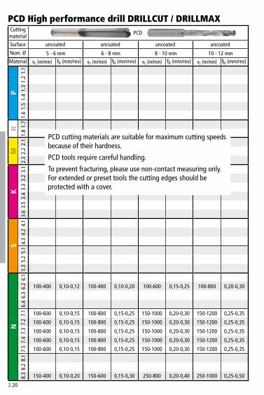
2.�0
5 - 6 mm 6 - 8 mm 8 - 10 mm 10 - 1� mm
vc (m/min) vc (m/min) vc (m/min) vc (m/min)
P1.
11.
�1.
�1.
41.
51.
6
H 1.7
1.8
M�.
1�.
��.
�
K�.
1�.
��.
��.
4�.
5�.
6
S4.
14.
�4.
�5.
15.
�5.
�
N6.
16.
� 100-400 0,10-0,1� 100-400 0,10-0,�0 100-600 0,15-0,�5 100-800 0,�0-0,�0
6.�
6.4
7.1 100-600 0,10-0,15 100-800 0,15-0,�5 150-1000 0,�0-0,�0 150-1�00 0,�5-0,�5
7.� 100-600 0,10-0,15 100-800 0,15-0,�5 150-1000 0,�0-0,�0 150-1�00 0,�5-0,�5
7.� 100-600 0,10-0,15 100-800 0,15-0,�5 150-1000 0,�0-0,�0 150-1�00 0,�5-0,�5
7.4 100-600 0,10-0,15 100-800 0,15-0,�5 150-1000 0,�0-0,�0 150-1�00 0,�5-0,�5
7.5 100-600 0,10-0,15 100-800 0,15-0,�5 150-1000 0,�0-0,�0 150-1�00 0,�5-0,�5
8.1
8.�
8.� 150-400 0,10-0,�0 150-600 0,15-0,�0 �50-800 0,�0-0,40 �50-1000 0,�5-0,50
Cutting material
PCD
Surface uncoated uncoated uncoated uncoated
Nom. Ø
Material fb (mm/rev) fb (mm/rev) fb (mm/rev) fb (mm/rev)
PCD High performance drill DRILLCUT / DRILLMAX
PCD cutting materials are suitable for maximum cutting speeds because of their hardness.
PCD tools require careful handling.
To prevent fracturing, please use non-contact measuring only. For extended or preset tools the cutting edges should be protected with a cover.

2.�1
6 mm 8 mm 10 mm 1� mm 16 mm �0 mm
vc fb vc fb vc fb vc fb vc fb vc fb
P1.
11.
�1.
�1.
41.
51.
6
H 1.7
1.8
M�.
1�.
��.
�
K�.
1�.
��.
��.
4�.
5�.
6
S4.
14.
�4.
�5.
15.
�5.
�
N6.
16.
� �00-600 0,04-0,08 �00-800 0,04-0,10 �00-800 0,04-0,1� �00-1000 0,04-0,15 �00-1000 0,06-0,�0 �00-1000 0,06-0,�0
6.�
6.4
7.1 �00-800 0,04-0,08 �00-800 0,04-0,10 400-1000 0,04-0,1� 400-1500 0,04-0,15 400-1500 0,06-0,�0 400-1500 0,06-0,�0
7.� �00-800 0,04-0,08 �00-800 0,04-0,10 400-1000 0,04-0,1� 400-1500 0,04-0,15 400-1500 0,06-0,�0 400-1500 0,06-0,�0
7.� �00-800 0,04-0,08 �00-800 0,04-0,10 400-1000 0,04-0,1� 400-1500 0,04-0,15 400-1500 0,06-0,�0 400-1500 0,06-0,�0
7.4 �00-800 0,04-0,08 �00-800 0,04-0,10 400-1000 0,04-0,1� 400-1500 0,04-0,15 400-1500 0,06-0,�0 400-1500 0,06-0,�0
7.5 �00-800 0,04-0,08 �00-800 0,04-0,10 400-1000 0,04-0,1� 400-1500 0,04-0,15 400-1500 0,06-0,�0 400-1500 0,06-0,�0
8.1
8.�
8.� �00-600 0,04-0,10 400-800 0,04-0,15 500-1�00 0,04-0,�0 500-1�00 0,04-0,�5 500-1�00 0,04-0,�5 500-1�00 0,04-0,�5
Cutting material
PCD
Surface uncoated uncoated uncoated uncoated uncoated uncoated
Nom. Ø
Material
PCD Drill slot milling tool
PCD cutting materials are suitable for maximum cutting speeds because of their hardness.
PCD tools require careful handling.
To prevent fracturing, please use non-contact measuring only. For extended or preset tools the cutting edges should be protected with a cover.

2.��
8 mm 10 - 1� mm 16 mm �0 mm
vc (m/min) vc (m/min)
P1.
11.
�1.
�1.
41.
51.
6
H 1.7
1.8
M�.
1�.
��.
�
K�.
1�.
��.
��.
4�.
5�.
6
S4.
14.
�4.
�5.
15.
�5.
�
N6.
16.
� �00-1000 0,04-0,08 0,05-0,10 �00-1500 0,04-0,15 0,05-0,�0
6.�
6.4
7.1 400-1500 0,04-0,08 0,04-0,10 400-�000 0,05-0,15 0,06-0,�0
7.� 400-1500 0,04-0,08 0,04-0,10 400-�000 0,05-0,15 0,06-0,�0
7.� 400-1500 0,04-0,08 0,04-0,10 400-�000 0,05-0,15 0,06-0,�0
7.4 400-1500 0,04-0,08 0,04-0,10 400-�000 0,05-0,15 0,06-0,�0
7.5 400-1500 0,04-0,08 0,04-0,10 400-�000 0,05-0,15 0,06-0,�0
8.1
8.�
8.� 400-1500 0,04-0,10 0,05-0,�0 500-�000 0,05-0,�0 0,06-0,�5
PCD Thread milling toolCutting material PCD MGF PCD GWF
Surface uncoated uncoated
Nom. Ø
Material fz (mm/tooth) fz (mm/tooth) fz (mm/tooth) fz (mm/tooth)
PCD cutting materials are suitable for maximum cutting speeds because of their hardness.
PCD tools require careful handling.
To prevent fracturing, please use non-contact measuring only. For extended or preset tools the cutting edges should be protected with a cover.

2.��
TiN
6 - 8 mm 8 - 10 mm 10 - �0 mm
vc (m/min)
P1.
11.
�1.
�1.
41.
51.
6
H 1.7
1.8
M�.
1�.
��.
�
K�.
1 �0-60 0,0�-0,10 0,04-0,10 0,07-0,10
�.� �0-60 0,0�-0,10 0,04-0,10 0,07-0,10
�.� �0-60 0,0�-0,10 0,04-0,10 0,07-0,10
�.4
�.5
�.6
S4.
14.
�4.
�5.
15.
�5.
�
N6.
16.
�6.
�6.
47.
17.
� 50-100 0,05-0,1� 0,06-0,15 0,07-0,15
7.� 50-100 0,05-0,1� 0,06-0,15 0,07-0,15
7.4
7.5
8.1
8.�
8.�
Drill reamer DREAMMAXCutting material Solid carbide
Surface
Nom. Ø
Material fb (mm/rev) fb (mm/rev) fb (mm/rev)
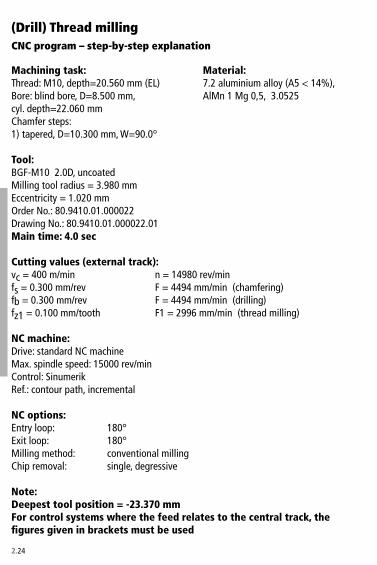
2.�4
CNC program – step-by-step explanation
(Drill) Thread milling
Machining task: Material:Thread: M10, depth=�0.560 mm (EL) 7.� aluminium alloy (A5 < 14%), Bore: blind bore, D=8.500 mm, AlMn 1 Mg 0,5, �.05�5cyl. depth=��.060 mm Chamfer steps:1) tapered, D=10.�00 mm, W=90.0°
Tool: BGF-M10 �.0D, uncoated Milling tool radius = �.980 mm Eccentricity = 1.0�0 mm Order No.: 80.9410.01.0000�� Drawing No.: 80.9410.01.0000��.01Main time: 4.0 sec
Cutting values (external track):vc = 400 m/min n = 14980 rev/minfs = 0.�00 mm/rev F = 4494 mm/min (chamfering)fb = 0.�00 mm/rev F = 4494 mm/min (drilling)fz1 = 0.100 mm/tooth F1 = �996 mm/min (thread milling)
NC machine: Drive: standard NC machine Max. spindle speed: 15000 rev/min Control: Sinumerik Ref.: contour path, incremental
NC options:Entry loop: 180°Exit loop: 180°Milling method: conventional millingChip removal: single, degressive
Note:Deepest tool position = -23.370 mmFor control systems where the feed relates to the central track, the figures given in brackets must be used
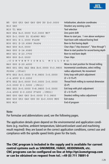
2.�5
N5 G00 G53 G40 G60 G90 D0 Z+0.0000 Initialisation, absolute coordinatesN10 G80 Deselect any existing cyclesN15 T1 M06 Tool selectionN20 G54 X+0.0000 Y+0.0000 M07 Zero point shiftN25 Z+1.0000 D1 S14980 M03 Move to start pos. 1 mm above workpieceN30 G01 Z-1.3000 F1498 Start bore with reduced boring feedN35 G01 Z-15.6580 F4494 Bore to first boring depthN40 G00 Z+0.0000 Clear chips (“chip clearance”, “blow through”)N45 G00 Z-14.6580 Move to start position for second boring depthN50 G01 Z-23.3700 Bore to end bore depthN55 G00 Z+0.0000 Clear chips;(C O N V E N T I O N A L M I L L I N G)
N60 G00 Z-20.4000 Move to start position for thread millingN65 G01 G91 G42 G64 X+0.0000 Y+3.9800 Incremental coordinates, select milling F2996 ;(F340) radius adjustment, No movementN70 G02 X+0.0000 Y-8.9800 I+0.0000 Entry loop with pitch adjustment J-4.4900 Z-0.2250 (Z = 0.15×P)N75 G02 X+0.0000 Y+0.0000 I+0.0000 Thread finish milling to nominal dimension J+5.0000 Z-1.5000 ;(F611) (Z=P)N80 G02 X+0.0000 Y+8.9800 I+0.0000 Exit loop with pitch adjustment J+4.4900 Z-0.2250 F7490 ;(F851) (Z = 0.15×P)N85 G00 G40 G60 X+0.0000 Y-3.9800 Deselect milling radius adjustmentN90 G00 G53 G40 G90 D0 Z+0.0000 M95 Exit statusN95 M30 End of program
Note: For formulae and abbreviations used, see the following pages.
The CNC program is included in the supply and is available for current control systems such as SINUMERIK, FANUC, HEIDENHAIN, etc.CNC programs can be configured on line at http://tpt.kometgroup.com or can be obtained on request from tel.: +49 (0) 711 78891-0
The application details given depend on the environmental and application condi-tions (e.g. machine, ambient temperature, lubricant/coolant used and machining result required): they are based on the correct application conditions, correct use and compliance with the spindle speed limits given for the tools.

2.�6
nzv
c
fz
frf
eggDR1
R�
zR�
R4
F1 = n × z × fz
erf + R1
F1 = n × z × fz ×
F� = n × z × fz
� × eD
F� = n × z × fz ×
F� = n × z × fz × �,5
F� = F� × �,5
Formula symbols and abbreviations used
Formulae – (Drill) Thread Milling
r.p.m.
m/minmm/teethmm/revmmmmmmmmmmmmmmmmmmmm
Spindle speedNo. of teethCutting speedMilling feedBoring feedTool radiusEccentricityAmount of withdrawal for conventional millingAmount of withdrawal for climb millingNominal thread diameterNominal thread radiusRadius entry loop, external path (J)z dimension entry and exit loop Radius entry loop, centre path (J)Radius full circle, centre path (=e)
Entry loop contour path
Entry loop centre point path
Full circle contour path
Full circle centre point path
Exit loop contour path
Exit loop centre point path
Path feeds

2.�7
vc × 1000D × p
n =
D × p × n1000
vc =
rf = R1 – e
e = R1 – rf
g = 1,� ×e
tan ( )+
a�
g = 1
e
tan ( )a�
D�
R1 =
rf + R1
�R� =
z = p × 0,15
e�
R� =
R4 = e
pitch
Cutting speed in m/min
Spindle speed in r.p.m.
Tool radius in mm
Eccentricity in mm
Amount of withdrawal for conventional milling in mm
Amount of withdrawal for climb milling in mm
Nominal thread radius in mm
Radius entry loop, external path (J) in mm
z dimension entry and exit loop in mm
Radius entry loop, centre path (J) in mm
Radius full circle, centre path (=e) in mm
Formulae
1 where a = 90° countersink angle = tan45° = 1 where countersink angle is 60° the amount of withdrawal is larger

2.�8
���
�������������������������
���
���
��
��
��
��
��
Lf (%)
Tool clamping• Correct alignment of clamping screw on clamping surface for Whistle-Notch adaptor• Minimise overhang but the cutting sweep for the tool should be beyond the adaptor
Material: heat treated steelRm = 1000 N/mm�
Cutting values: size: M10vc = 100 m/min fz = 0,06 mm/tooth
Tool measurement• Only measure tool length on pre-setter.• Check concentricity at drill tip resp. thread milling section <0.0� mm• Use tool radius shown on the CNC program
Preparations on machine• Inkey tool length and tool radius into offset register of the control
Program test• Do a test run over the workpiece (increase tool length in tool record)• Check machining time. If the time recorded is clearly different to that given in the
program, there is an error in the feed rate calculation (contour path/centrer point path
• Optimise coolant supply. If flood coolant used, i.e. direct coolant flow onto the milling section of the tool. For through holes use flood coolant if there is no lateral flute coolant supply on the tool.
Setting (drill) thread milling tools Preparations on tool
thermal expansion or hydr. expansion chuckHE cyl. with side screw
collet
run-out error (µm)
Effect of concentricity on tool life using a solid carbide thread milling tool as an example

2.�9
Cast aluminium• Can be carried out without peck cycle• For tools with internal coolant there is no need for chip clearance after boring.
Milling method for different materials
Long chipping aluminium • At least once peck cycle• Radial division of cut may be necessary if a thread with very low burring is required
Grey cast iron• No chip clearance• Conventional thread milling in one path. Over �×D two pathes may be required.
Special casesThrough hole• For tool with internal coolant, switch to
external coolant for milling• To reduce side load, preferably work with
milling section on shank side
Angled bore exit / cutting through cross holes• Reduce bore feed rate at bore exit by 60%
Cavities (inclusions) in cast materials • Reduce bore feed rate by 40-60%

2.�0
Chips packed or glued at the thread profile• poor coolant > improve coolant (i.e. add flood coolant, lateral flute coolant
supply for through holes)> add coolant flutes flutes on shank
Problems – causes > solutions
Drill thread milling tool
Thread go-gage doesn’t fit• thread too small> reduce tool radius in offset register• chips in thread> improve coolant
Thread is getting tapered• poor tool clamping > improve tool holding (i.e. shrink fit holders)• thread milling feed too high> reduce thread milling feed
Erratic tool wear• tool run out too high > use better tool holders (i.e. shrink fit holders)
Counterbore chips are winding around the tool• chamfer feed too low > increase chamfer feed
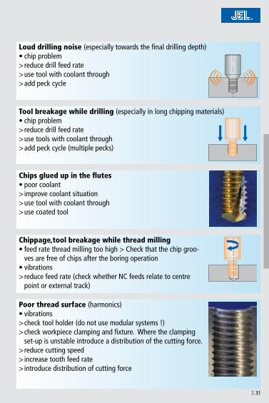
2.�1
Loud drilling noise (especially towards the final drilling depth)• chip problem > reduce drill feed rate> use tool with coolant through> add peck cycle
Tool breakage while drilling (especially in long chipping materials)• chip problem> reduce drill feed rate> use tools with coolant through> add peck cycle (multiple pecks)
Chips glued up in the flutes• poor coolant > improve coolant situation> use tool with coolant through> use coated tool
Chippage,tool breakage while thread milling• feed rate thread milling too high > Check that the chip groo-
ves are free of chips after the boring operation• vibrations > reduce feed rate (check whether NC feeds relate to centre
point or external track)
Poor thread surface (harmonics)• vibrations > check tool holder (do not use modular systems !)> check workpiece clamping and fixture. Where the clamping
set-up is unstable introduce a distribution of the cutting force.> reduce cutting speed> increase tooth feed rate> introduce distribution of cutting force

2.��
Chips packed or glued at the thread profile• poor coolant > improve coolant situation (i.e. add flood coolant, lateral flute
coolant supply for through holes)> add coolant flutes on shank
Problems – causes > solutions
Thread milling tool
Thread go-gage doesn’t fit• thread too small > reduce tool radius in offset register• chips in thread > improve coolant
Thread is getting tapered• poor tool clamping > improve tool holding (i.e. shrink fit holders)• thread milling feed too high > reduce thread milling feed
Erratic tool wear• tool run out too high > use better tool holders (i.e. shrink fit holders),check material
for homogeneity
Chippage, tool breakage• feed rate thread milling too high> reduce thread milling feed• vibrations> check tool holder (don’t use modular systems!!), change feeds
and speeds
Poor thread surface• tool overhang too long> check part clamping an and fixture. Use multiple cuts when part
is clamped weak.• non-suitable tool for this application> reduce cutting speed, increase feed/tooth, prefer conventional
milling

2.��
Thread too tight• tolerance of thread forming tool does not align with thread
gauge> use thread forming tool with right tolerance
Problems – causes > solutions
Roll form tap
Core diameter too large on thread• wrong drill diameter (too large) > use smaller drill
Core diameter too small or torque too high• drill diameter too small > use larger core boring tool
Forming gap

2.�4
Oversized thread• wrong tools > select the right tools as shown in the JEL catalogue
• cutting edge geometry not suitable for materials to be machined> select the right tools as shown in the JEL catalogue
• material built-up at tap flanks> improve coolant system> use coated tap
• minor diameter too small, tool is cutting full profile> select correct core diameter
• chip jam> blind bore: increase spindle speed. Correct tool selection (spiral flute)> through hole: correct tool selection (spiral point)
• tolerance of tap drill to thread gauge does not agree> use tap drill with right tolerance
• angular or positional error in core bore> adjust workpiece clamping, use tapping chuck with axis parallel float
Problems – causes > solutions
Tap
Thread too tight• tolerance of tap drill to thread gauge does not agree > use tap drill with right tolerance• wrong tool type > select the right tools as shown in the JEL cata-
logue
Thread is cut wrongly axially• cutting lead pressure on tapping chuck too great> select the right cutting lead pressure
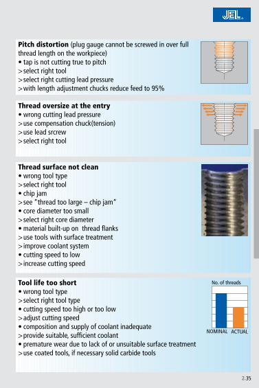
2.�5
Pitch distortion (plug gauge cannot be screwed in over full thread length on the workpiece)• tap is not cutting true to pitch > select right tool> select right cutting lead pressure> with length adjustment chucks reduce feed to 95%
Thread oversize at the entry• wrong cutting lead pressure > use compensation chuck(tension) > use lead srcrew> select right tool
Thread surface not clean• wrong tool type > select right tool• chip jam > see “thread too large – chip jam“ • core diameter too small > select right core diameter• material built-up on thread flanks> use tools with surface treatment> improve coolant system• cutting speed to low > increase cutting speed
Tool life too short• wrong tool type > select right tool type• cutting speed too high or too low > adjust cutting speed• composition and supply of coolant inadequate > provide suitable, sufficient coolant• premature wear due to lack of or unsuitable surface treatment> use coated tools, if necessary solid carbide tools
NOMINAL ACTUAL
No. of threads

3.�
Dihart Precision Tools
Dihart supplies a wide range of standard reaming tools. Dihart also specialises in designing and producing tools according to customers’ specifications, for achieving the highest standard of machine finishing.Modern machines operating in air-conditioned halls guarantee a maximum of precision for the manufacture of high-performance tools.

3.�
3.4 – 3.5
3.6 – 3.7
3.8 – 3.93.10 – 3.113.1� – 3.1�3.14 – 3.15
3.163.17
3.183.19
3.�0 – 3.�13.��3.��
3.�4 – 3.�5
3.�6 – 3.�7
3.�8
Index Reaming
Recommended cutting data (Guidelines) Left-hand fold pageProduct Overview – Reamers
Assembly Instruction • Reamax®
• Rapid Set Heads• Cutting Rings• Monomax® – expandable• DAH® Compensation Holder• Hydro-expansion Chuck• DPS Floating Holder
Cutting Data • Cutting speed• Feed Geometries • Standard Geometries / Special Geometries• Cutting Materials and Coatings• ASG Cutting Geometry
Types of Tool Wear
Technical Application Hints • Fault – Cause – Remedy• Measurement

3.4
1,
40
4,
00
5,
60
9,
60
1�,
50
1�,
70
17,
60
�0,
10
40,
00
60,
00
1�9,
59
�00,
59
*
Overview Standard ReamersDihart offers standard reamers with a diameter range from 1,4 to �00,59 mm.
According to diameter
* Diameter 1�9,60 to �00,59 mm on request.
Tool Attachment
HSK-A, DAH®, ABS®, Cylindrical Shank, Morse Taper, ISO Taper
Cylindrical Shank, Morse Taper,
Cylindrical Shank, Morse Taper,
Cylindrical Shank
DAH®, Cylindrical Shank
HSK-A, DAH®, ABS®, Cylindrical Shank, Morse Taper,
Cylindrical Shank

3.5
According to system
Solid
Modular
Expandable
Monobloc

3.6
Reamax®
M
Reamax® Assembly Instruction
• Diameter range 1�,5 - �1.999 mm, 6 cutting edges
• Diameter range �� - 40 mm, 8 cutting edges
• Cylindrical shank �×D and 5×D
• DAH® Compensation Holder 5×D
• Modular tooling system
• High precision changing through face and taper contact
• New multiple-cutting reaming technology
• Optimised for application with mist coolant
• Highest cutting capacity
Apply light grease on tie bar thread
Clean taper/face contact thoroughly (grease free)
Before tightening the replaceable insert and tie bar, turn in a clockwise direction until it stops
For nominal size �, 4 and 5, locate marks on insert and tie bar for correct fitting
Serie 640
Fitting the replaceable insert
• Clean the taper and face contact on insert and holder thoroughly (grease free).• Apply light grease on tie bar threads.• Locate tie bar on insert and holder. Important note: for nominal size �, 4 and 5, fit with marking on tie bar and insert
aligned.• Draw in tie bar with the clamping nut. Before tightening, turn insert and tie bar
clockwise until it stops.• Tighten the clamping nut as far as possible using the torque key to the specified
starting torque M.

3.7
1 1�,500 - 15,999 16 81 1� 4 640.43.001 640.43.011 4 – 5
� 16,000 - �1,999 �0 81 14 5 640.43.002 640.43.012 6 – 7
� ��,000 - �5,999 �5 81 19 7 640.43.003 640.43.013 10 – 1�
4 �6,000 - ��,000 �5 – �� 8 640.43.004 640.43.014 18 – �0
4 �6,000 - ��,000 – 81 �4 8 640.43.004 640.43.014 18 – �0
5 ��,001 - 40,000 �� 81 �7 10 640.43.005 640.43.015 �6 – �8
Serie 640
Loosen the clamping screw
Locate hexagonal key in insert and loosen insert by turning
Removing the replaceable insert
• Loosen the clamping screw.• Pull tie bar from holder and insert.• Locate hexagonal key in insert and loosen insert by turning.
Dia.
-ran
ge [m
m]
Cylin
dric
al s
hank
DAH
Nom
inal
siz
e
Wid
th a
cros
s fla
ts [m
m]
Hexa
gon
sock
et [m
m]
Order No. Torq
ue M
[Nm
]
Order No.
Hexagon wrench
Hexagon wrench
extra long
Reamax® Disassembly Instruction

3.8
Rapid Set Head
• Diameter range 9,6 - 60 mm
• 4 - 6 cutting edges
• Internal coolant supply
• Holders – cylindrical, Morse taper, ABS®, DAH®, HSK
• Modular tooling system
• Simple and fast tool change
• Left hand cutting edges for maximum productivity
• Perfect accuracy
• Various cutting materials and coatings

3.9
M
1�,60 – 15,59 0,7 – 0,9
15,60 – 18,59 1,1 – 1,4
18,60 – �4,00 1,8 – �,�
�4,01 – 40,00 �,0 – �,8
40,01 – 60,00 5,� – 6,6
1 x
Dia.-range [mm]
Torque M[Nm]
Rapid Set Head – Assembly InstructionSerie 540
Each Rapid Set Head is delivered with slightly greased taper. Do not wipe off! Taper must be slightly greased with copper grease (Order-No.: 15K.10.10001)!
Clean taper in holder thoroughly free of grease
Turn left-/right screw one rotation into the Head (counter-clockwise thread).
Before tightening turn the drive keys of the Rapid Set Head against the direction of machining until it hits the holder.
Tightening the left-/right screw. Observe the specified starting torque M in the index table.
Rapid Set Heads up to Diameter 1�,59 mm are assembled with a clamping screw at the back of the holder. The screw has a counter-clockwise thread.
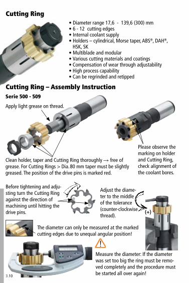
3.10
(+)
Cutting Ring• Diameter range 17,6 - 1�9,6 (�00) mm• 6 - 1� cutting edges• Internal coolant supply• Holders – cylindrical, Morse taper, ABS®, DAH®,
HSK, SK• Multiblade and modular• Various cutting materials and coatings• Compensation of wear through adjustability• High process capability• Can be regrinded and retipped
Cutting Ring – Assembly InstructionSerie 500 - 509
Apply light grease on thread.
Clean holder, taper and Cutting Ring thoroughly free of grease. For Cutting Rings > Dia. 80 mm taper must be slightly greased. The position of the drive pins is marked red.
Please observe the marking on holder and Cutting Ring, check alignment of the coolant bores.
Before tightening and adju-sting turn the Cutting Ring against the direction of machining until hitting the drive pins.
Adjust the diame-ter to the middle of the tolerance (counter-clockwise thread).
The diameter can only be measured at the marked cutting edges due to unequal angular position!
Measure the diameter: If the diameter was set too big the ring must be remo-ved completely and the procedure must be started all over again!

3.11
18 – �5 16 – 18
�6 – �� �5 – �8
�� – 40 48 – 55
41 – 45 65 – 75
46 – 60 90 – 110
61 – 79 1�0 – 140
80 – 100 180 – ��0
M
(+)
Cutting Ring – Assembly Instruction
Dia.-range [mm]
Torque M[Nm]
Apply light grease on threads of conical screw.
Clean holder, taper, grinding surfaces and Cutting Ring thoroughly free of grease.For Cutting Rings > Dia. 80 mm taper must be slightly greased. The position of the drive pins is marked red.
Screw the nut onto the holder with the smooth face against the bush. Mount the Cutting Ring with the conical screw.
After fastening the conical screw check that there is space between bush and ring. Fasten conical screw according to index table.
Before tightening and adjusting turn the Cutting Ring against the direction of machining until hitting the drive pin.
Please observe the marking on holder and Cutting Ring, check alignment of the coolant bores.
Adjust the diameter to the middle of the tolerance.
The diameter can only be measured at the marked cutting edges due to unequal angular position!
Measure the diameter.If the diameter was set too big the ring must be removed completely and the procedure must be started all over again!
Serie 510 - 519

3.1�
Monomax® – expandable
• Diameter range 5,6 - 40.6 mm
• 4 - 8 cutting edges
• Internal coolant supply
• Cylindrical shank and Morse taper
• High efficiency
• Smallest bore tolerances can be reached
• Straight- and left hand fluted for defined chip flow
• Maximum production reliability
• Compensation for wear through easy adjustment

3.1�
15A.11.�00xx
15A.10.�00xx
Monomax® – expandable
Central coolant outlet
Lateral coolant outlet
Taper screw Reamer
Taper screw Reamer

3.14
Dihart Compensation Holder DAH®
Assembly- and Adjusting Instruction
Pre-load evenly with the 6 assem-bling screws (compressing the spring washer)
Clean grinding surfaces thoroughly dry and free of grease

3.15
6� 7 – 9
81 7 – 9
115 �5 – �5
M
DAHØ d1 [mm]
Torque M[Nm]
Assembly- and Adjusting Instruction DAH®
Adjusting the DAH® must be done in the machine on the spindle where the tool will be in use afterwards!
Center the indicator if possible on the gauge line. If non existent, measure at the cutting edges.
Tighten the screws cross-wise. Please observe the specified starting torque M in the index-table.
After fastening, fix the adjusting ring by locking the setscrew.
Finally check the runout once more. «should be» < 5 µm.
Determine the highest position by tur-ning against the direction of machining (largest runout error).Bring the setscrew and hexagonal key to the highest position by turning the adjusting ring.Correct half of the measured runout error by inserting the setscrew.Repeat this procedure until the runout error is < 5 µm.

3.16
In comparison to previous solutions the hydro-expansion chuck is integrated into the new Dihart compensating holders. This means one less interface. Four adjustable screws allow rapid and precise adjustment of the concentricity of the multiple blade reamer, reducing concentricity errors to virtually zero. The extremely slim design of these new compensating holders ensures that they fit easily into practically all tool magazines.
Adjustment of con-centricity on cutter to virtually „zero“ µm
Simple handling – reduced machine idle times
Connection on tool-side with expansion chuck
Connection on machine side:SK 40; HSK 6�
Simple, time-saving control using ad-justment ring with adjustment screw
Alignment module:1 Adjustment ring4 Adjustment screws
Tightening screwfor clamping tool

3.17
Dihart Floating Holder DPS
• cost reducing
• long tool life for tools
• consistent results with batch production
• reduction in waste and re-working
• slim design
• no worn parts
• no adjustment
For use on turning machines

3.18
min/max min/max min/max min/max min/max min/max min/max min/max min/max min/max min/max min/max
P1.
0 6-10 70-�00 60-165 70-�00 70-�00 6-10 70-145 60-1�0 70-145 70-145
�.0 6-10 80-�00 65-165 80-�00 80-�00 6-10 60-145 50-1�0 60-145 60-145
�.1 15-45 80-�00 65-165 80-�00 80-�00 15-45 60-145 50-1�0 60-145 60-145
�.0 5-9 80-1�0 65-110 80-1�0 80-1�0 5-9 60-95 50-80 60-95 60-95
4.0 4-7 15-45 4-7 10-�0
4.1 �-5 10-�0 �-5 10-�0
S5.
0 4-7 15-45 4-7 10-�0
5.1 5-1� 5-1�
M6.
0 5-8 15-45 5-8 10-�0
6.1 4-6 10-�5 4-6 10-�5
7.0 4-6 10-�5 4-6 10-�5
K8.
0 10-�5 �5-1�0 50-�00 10-�5 �5-95 �5-145
8.1 6-1� �0-90 �5-1�0 6-1� 15-65 �5-95
9.0 9-18 1�0-�95 160-�55 160-�55 9-18 95-�15 115-�60 115-�60
9.1 9-18 110-�50 1�0-�95 1�0-�95 9-18 80-180 95-�15 95-�15
10.0 8-15 65-�00 55-165 85-�50 85-�50 8-15 50-145 40-1�0 60-180 60-180
10.1 6-1� �5-65 50-100 6-1� �5-50 �5-70
10.� 6-1� �0-90 �5-1�0 6-1� 15-65 �5-95
N1�
.0 10-�0 100-��0 85-�75 10-�0 70-�40 60-�00
1�.1 10-�0 65-�00 55-165 10-�0 70-�40 60-�00
1�.0 10-�0 110-��0 10-�0 80-�40
1�.1 10-�0 110-550 10-�0 80-400
14.0 8-�0 110-440 8-�0 80-��0
H 15.0
16.0
Mat
eria
l gro
up Reamers short Reamers longCutting materials and coatings Cutting materials and coatings
on request
Guideline values for reamers: Cutting speed vc (m/min)

3.19
< Ø8 Ø8-�5 Ø�5-50 > Ø50 < Ø8 Ø8-�5 Ø�5-50 > Ø50 < Ø8 Ø8-�5 Ø�5-50 > Ø50
P1.
0 0,05- 0,08
0,07- 0,1�
0,09- 0,�0
0,10- 0,�5
0,07- 0,1�
0,10- 0,17
0,1�- 0,�4
0,1�- 0,�0
0,07- 0,1�
0,10- 0,17
0,1�- 0,�4
0,1�- 0,�0
�.0 0,05-
0,080,07- 0,1�
0,09- 0,�0
0,10- 0,�5
0,07- 0,1�
0,10- 0,17
0,1�- 0,�4
0,1�- 0,�0
0,07- 0,1�
0,10- 0,17
0,1�- 0,�4
0,1�- 0,�0
�.1 0,05-
0,080,07- 0,1�
0,09- 0,�0
0,10- 0,�5
0,07- 0,1�
0,10- 0,17
0,1�- 0,�4
0,1�- 0,�0
0,07- 0,1�
0,10- 0,17
0,1�- 0,�4
0,1�- 0,�0
�.0 0,04-
0,060,05- 0,09
0,07- 0,15
0,08- 0,19
0,05- 0,09
0,07- 0,1�
0,09- 0,18
0,10- 0,��
0,05- 0,09
0,07- 0,1�
0,09- 0,18
0,10- 0,��
4.0 0,0�-
0,050,05- 0,08
0,06- 0,1�
0,07- 0,16
4.1 0,0�-
0,050,05- 0,08
0,06- 0,1�
0,07- 0,16
S5.
0 0,0�- 0,05
0,05- 0,08
0,06- 0,1�
0,07- 0,16
5.1 0,0�-
0,050,07- 0,14
0,10- 0,�4
0,11- 0,�0
M6.
0 0,0�- 0,05
0,05- 0,08
0,06- 0,1�
0,07- 0,16
0,05- 0,08
0,06- 0,11
0,08- 0,16
0,08- 0,�0
6.1 0,0�-
0,050,05- 0,08
0,06- 0,1�
0,07- 0,16
0,05- 0,08
0,06- 0,11
0,08- 0,16
0,08- 0,�0
7.0 0,0�-
0,050,05- 0,08
0,06- 0,1�
0,07- 0,16
K8.
0 0,06- 0,09
0,08- 0,1�
0,10- 0,��
0,11- 0,�8
0,08- 0,1�
0,11- 0,18
0,1�- 0,�6
0,14- 0,��
8.1 0,06-
0,090,08- 0,1�
0,10- 0,��
0,11- 0,�8
9.0 0,06-
0,090,08- 0,1�
0,10- 0,��
0,11- 0,�8
0,08- 0,1�
0,11- 0,18
0,1�- 0,�6
0,14- 0,��
9.1 0,06-
0,090,08- 0,1�
0,10- 0,��
0,11- 0,�8
0,08- 0,1�
0,11- 0,18
0,1�- 0,�6
0,14- 0,��
10.0 0,06-
0,090,08- 0,1�
0,10- 0,��
0,11- 0,�8
0,08- 0,1�
0,11- 0,18
0,1�- 0,�6
0,14- 0,��
10.1 0,06-
0,090,08- 0,1�
0,10- 0,��
0,11- 0,�8
10.� 0,06-
0,090,08- 0,1�
0,10- 0,��
0,11- 0,�8
N1�
.0 0,05- 0,08
0,07- 0,1�
0,09- 0,�0
0,10- 0,�5
0,07- 0,1�
0,10- 0,17
0,1�- 0,�4
0,1�- 0,�0
1�.1 0,05-
0,080,07- 0,1�
0,09- 0,�0
0,10- 0,�5
0,07- 0,1�
0,10- 0,17
0,1�- 0,�4
0,1�- 0,�0
1�.0 0,05-
0,100,07- 0,14
0,09- 0,�4
0,10- 0,�0
0,07- 0,14
0,10- 0,�0
0,1�- 0,�9
0,1�- 0,�6
1�.1 0,05-
0,100,07- 0,14
0,09- 0,�4
0,10- 0,�0
14.0 0,05-
0,100,07- 0,14
0,09- 0,�4
0,10- 0,�0
H 15.0
16.0
0,10- 0,�0
0,10- 0,�0
0,�0- 0,40
0,�0- 0,40
0,10- 0,�0
0,10- 0,�0
0,�0- 0,40
0,�0- 0,40
0,10- 0,�0
0,10- 0,�0
0,�0- 0,40
0,�0- 0,40
Guideline values for reamers: Feed fz (mm/tooth)M
ater
ial g
roup
Straight Fluted Left Hand Flutedwithout interrupted cut, chip deflection, chip breaker geometry
ASG07 · ASG01 etc. ASG09B · ASG09 etc. ASG05 · ASG 0501 etc.Feed fz (mm/tooth) Feed fz (mm/tooth) Feed fz (mm/tooth)
Reaming allowance in Ø (mm)
Feed values for titanium alloys relate to ASG0� and ASG0�01
on request

3.�0
ASG
01
ASG
0�
ASG
04
ASG
05
ASG
050
1AS
G 0
6
ASG
07
45°
45°
8°
�0°
4°
�5°
�5°
0,� x 45°
90°
45°
Geo-metry
Bevel angles Chip evacuation Flute form Cutting materials and coatings
Straight Fluted
Straight Fluted
Left Hand Fluted
Left Hand Fluted
Left Hand Spiraled
Straight Fluted
Straight Fluted
Standard Geometries
Face Cutting
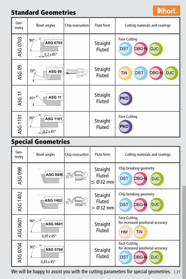
3.�1
ASG
070
�
ASG
09
ASG
11
ASG
110
1
90°
0,� x 45°
�0°
45°
0,� x 45°
ASG
09B
ASG
140
�
ASG
060
1
ASG
070
4
0,05 x 45°
0,05 x 45°
90°
90°
90°
Geo-metry
Bevel angles Chip evacuation Flute form Cutting materials and coatings
Straight Fluted
Straight Fluted
Straight Fluted
Straight Fluted
Geo-metry
Bevel angles Chip evacuation Flute form Cutting materials and coatings
Straight Fluted
Ø �� mm
Straight Fluted
Ø �� mm
Straight Fluted
Straight Fluted
Face Cutting
Face Cutting
Special Geometries
Standard Geometries
Chip breaking geometry
Face Cutting, for increased positional accuracy
Face Cutting, for increased positional accuracy
Chip breaking geometry
We will be happy to assist you with the cutting parameters for special geometries.

3.��
P S M K N H
GGG
Cutting Materials and CoatingsGeneral: These cutting materials and coatings can be used for all types of reaming tools.
This does not include PCD material.
Basic recommendation
Description For workpiece material
Cutt
ing
Mat
eria
ls
DSA (carbide) is a finely-grained-hard metal (K05-K10) for conventional reaming. It stands out because of its high abrasion resistance and gives good results in most commonly used materials.It is very suitable for coating, and therefore mainly used also as cutting material for coated reamers.
DST (Cermet) is a high-performance cutting material, and very suitable for high-speed reaming. DST is ideal for machining non-alloyed or low alloyed steels up to 1�00 N/mm� tensile strength. DST is also excellent for reaming nodular iron.
PCD (polycrystalline diamond) is a high-performance cutting material, and suitable for high-speed reaming non-ferrous metals, such as aluminium, magnesium etc. Because of its very high abrasion resistance it is excellent for machining high-silicium content aluminium alloys.
Coat
ings
TiN is an all purpose coating material. It has a very smooth sur-face and has very little affinity to many materials. This avoids structure deformation which gives excellent surface-finish results when reaming, and with considerably higher cutting data than with non coated carbide reamers.
DBG-N is a TiAlN coating, which offers a very high grade of hardness of approximately ��00 HV. The coating also has a very high oxidation resistance. This makes this particular high-performance coating very suitable for high cutting speeds, and also for using with mist coolant machining.
DJC is a combination of the high-performance cutting material DST (Cermet) and the high-performance coating DBG. With this combination a very high tool life with extremely high cutting data can be reached.
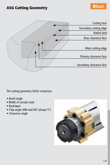
3.��
ASG Cutting Geometry
The cutting geometry (ASG) comprises:
• Bevel angle• Width of circular land• Backtaper• Chip angle (HM and DST always 5°)• Clearance angle
Cutting face
Secondary cutting edge
Radial land
Rear clearance face
Main cutting edge
Primary clearance face
Secondary clearance face

3.�4
Types of tool wear
Flank wear Reduce cutting speed or use a cutting material or coating with higher abrasion resistance.
Major breakage Reduce feed rate and stock allowanceUse carbide with coating instead of cermet for interrupted bores.
Pitting of chip surfaceReduce cutting speed or use a more positive rake angle.
Edge wear Increase cutting speed or use a more positive rake angle.
Fatigue wear Reduce feed rate, increase stability of the reamer.
Notch wear Reduce cutting speed or use a cutting material or coating with higher abrasion resistance.
Built-up on chip surface Increase cutting speed and use positive geometry.
Hairline cracks Use enough coolant and inner coolant supply, reduce cutting speed.

3.�5
Examples of Tool Wear
Notch wear Notch wear
Built-up
Flank wear Flank wear
Built-up

3.�6
Technical Application Hints
Bore too large• Reamer is not running true in the spindle > Use DAH® Compensation Holder• Alignment not precise, reamer cuts at the back end > Correct alignment or use DAH® Compensation Holder• Built-up edge > Use another coolant, if necessary reduce cutting speed• Reamer too big > Repair Reamer by replacing blades
Fault • Cause > Remedy
Tapered bore• Faulty alignment > Correct alignment or use DAH® Compensation Holder or DPS-Floating Holder• Misalignment of head-stock with tail-stock > Correct tail-stock or use DAH® Compensation Holder or DPS-Floating Holder
Bore too small• Reamer too small in diameter > Use reamer with correct diameter• Worn reamer > Expand, regrind or replace reamer• Reaming allowance too small > Increase reaming allowance
Lipped bore• Faulty alignment. Cutting edges press at start > Correct alignment or use DAH® Compensation Holder or DPS-Floating Holder• Cutting edge tail cuts especially when shank sags in floating holder > Ensure better axial alignment. Fasten floating holder if it can be corrected
axially. Fix reamer rigidly.
Bore not true, shows chatter marks• Concentricity and alignment error of tool and spindle to large > Correct alignment and true run or use DAH® Compensation Holder• Asymmetrical cutting through uneven entry surface > Countersink bore• Deformation through clamping of the work piece > Correct clamping of the work
piece

3.�7
Reamer works hard, Reamer jams• Reduced back taper because taper adjusting screw has loosened > Cylindrical grinding with adequate taper, resharpen• Circular land too wide > Make a relief grind as instructed• Edge clearance not ground away after cylindrical grinding > Regrind face
Scoring in bore «feed marks»• Different height of bevels or teeth > Check concentricity of bevel and circular land and if necessary regrind• Built-up edge > Reduce cutting speed
Scoring in bore «retraction marks»• Feeding the reamer blades past end of bore > Through bore: Bevel angel + � mm past bore exit• Machine is not solid enough > Retraction not with rapid but with increased feed
Surface quality unsatisfactory• Cutting edges blunt or notched > Regrind correctly• Bevel not uniform > Give bevel accurate regrinding• Reamer does not run true > Check cylindrical accuracy of edges or use DAH® Compensation Holder• Wrong machining data > Follow recommendations• Failing or insufficient coolant, chips getting jammed > Supply proper coolant with strong jet. If possible use tools with internal coo-
lant supply

3.�8
180 º
• Unequal angular position!• Only two cutting edges are 180° in opposite line.• Measuring teeth• Because the tools are tapered measurement has to be done at the front of the
cutting edge.• PCD tipped reamers require non-contact measuring device!
Measurement
3.�9
Notice

P1.
0
# 500
2.0 500-900
2.1 < 500
3.0 > 900
4.0 > 900
4.1
S5.
0 250
5.1 400
M6.
0
# 600
6.1 < 900
7.0 > 900
K8.
0 180
8.1 250
9.0
# 600 130
9.1 230
10.0 > 600 250
10.1 200
10.2 300
N12
.0 90
12.1 100
13.0 60
13.1 75
14.0 100
H 15.0 1400
16.0 1800
P1.
1
# 400 # 120
1.2
# 700 # 200
1.3
# 850 # 250
1.4
# 850 # 250
1.5 > 850, # 1200 > 250, # 350
1.6 > 1200 >350
H 1.7
# 1400 # 400
1.8
# 2200 # 600
M2.
1
# 850 # 250
2.2
# 850 # 250
2.3
# 1000 # 300
K3.
1
# 500 # 150
3.2 > 500, # 1000 > 150, # 300
3.3
# 700 # 200
3.4 > 700, # 1000 > 200, # 300
3.5
# 700 # 200
3.6 > 700, <1000 > 200, # 300
S4.
1
# 700 # 200
4.2
# 900 # 270
4.3 > 900, # 1250 > 270, # 300
5.1
# 500 # 150
5.2
# 900 < 270
5.3 > 900, # 1200 > 270, # 350
N6.
1
# 350 # 100
6.2
# 700 # 2006.
3
# 700 # 200
6.4
# 500 # 470
7.1
# 350 # 100
7.2
# 600 # 180
7.3
# 600 # 180
7.4
# 600 < 180
7.5
# 600 # 180
8.1
8.2
8.3
Mat
eria
l gro
up
Stre
ngth
Rm
[N/m
m2 ]
Hard
ness
HB
Material
magnetic soft iron
structural, case hardened steel
carbon steel
alloy steel
alloy / heat treated steel
alloy / heat treated steel
hardened steel to 45 HRC
hardened steel to 58 HRC
stainless steel, sulphuretted
stainless steel, austentic
stainless steel, ferritic, ferritic & austentic, martensitic
grey cast iron
grey cast iron, heat treated
spheroidal graphite cast iron
spheroidal graphite cast iron, heat treated
malleable iron
malleable iron, heat treated
pure titanium
titanium alloys
titanium alloys
pure nickel
nickel alloys, heat resistant
nickel alloys, high heat resistant
non-alloy copper
short chip, brass, bronze, red brass
long chip brass
Cu-Al-Fe-alloy (Ampco)
Al, Mg, non-alloy
Al wrought alloy, breaking strain (A5) < 14%
Al wrought alloy, breaking strain (A5) $ 14%
Al cast alloy, Si < 10%
Al cast alloy, Si $ 10%
Thermoplastics
Thermosetting plastics
Fibre reinforced plastics
Selecting the material – ThreadingSelecting the material – Drilling / Reaming
Mat
eria
l gro
up
Stre
ngth
Rm
[N/m
m2 ]
Hard
ness
HB
MaterialMaterial example material code/DIN
non-alloy steels St37-2/1.0037; 9SMn28/1.0715; St44-2/1.0044
non-alloy / low alloy steels St52-2/1.0050; C55/1.0525; 16MnCr5/1.7131
lead alloys 9SMnPb28/1.0718
non alloy / low alloy steels: heat resistant structural, heat treated, nitride and tools steels 42CrMo4/1.7225; CK60/1.1221
high alloy steels X6CrMo4/1.2341; X165CrMoV12/1.2601
HSS
special alloys Inconel 718/2.4668; Nimonic 80A/2.4631
titanium, titanium alloys TiAl5Sn2/3.7114
stainless steels X2CrNi189/1.4306; X5CrNiMo1810/1.4401
stainless steels X8CrNb17/1.4511; X10CrNiMoTi1810/1.4571
stainless / fireproof steels X10CrAl7/1.4713; X8CrS-38-18/1.4862
gray cast iron GG-25/0.6025; GG-35/0.6035
alloy gray cast iron GG-NiCr202/0.6660
spheroidal graphite cast iron (ferritic) GGG-40/0.7040
spheroidal graphite cast iron (ferritic/perlitic)GGG-50/0.7050; GGG-55/0.7055; GTW-55/0.8055spheroidal graphite cast iron (perlitic), malleable iron GGG-60/0.7060; GTS-65/0.8165
alloyed spheroidal graphite cast iron GGG-NiCr20-2/0.7661
vermicular cast iron GGV Ti<0,2; GGV Ti>0,2
copper alloy, brass, lead-alloy bronze, lead bronze (good cut) CuZn36Pb3/2.1182; G-CuPb15Sn/2.1182
copper alloy, brass, bronze (average cut) CuZn40Al1/2.0550; E-Cu57/2.0060
wrought aluminium alloys AlMg1/3.3315; AlMnCu/3.0517
cast aluminium alloy (Si-content <10%), magnesium alloyG-AlMg5/3.3561; G-AlSi9Mg/3.2373
cast aluminium alloy (Si-content >10%) G-AlSi10Mg/3.2381
hardened steels (< 45 HRC)
hardened steels (> 45 HRC)
NotesPatentesABS® EP 0 547 049 and other patentsKUB Quatron® patent applicationsKUB Trigon® EP 883 455 and other patentsKUB Duon® EP 1 296 793 and other patents and patent applicationsKUB Centron® EP 0 586 423 and other patent applications KUB® V464 EP 0 586 423 and other patentsTwinKom® G01 EP 0 472 562, EP 0 472 563 and other patentsUniTurn® EP 0 973 625 and other patents and patent applicationsMicroKom® M03Speed EP 0 484 407 and other patentsMicroKom® M040 EP 0 491 724 and other patentsReamax® EP 1 259 350, EP 1 474 258

P1.
0
# 500
2.0 500-900
2.1 < 500
3.0 > 900
4.0 > 900
4.1
S5.
0 250
5.1 400
M6.
0
# 600
6.1 < 900
7.0 > 900
K8.
0 180
8.1 250
9.0
# 600 130
9.1 230
10.0 > 600 250
10.1 200
10.2 300
N12
.0 90
12.1 100
13.0 60
13.1 75
14.0 100
H 15.0 1400
16.0 1800
P1.
1
# 400 # 120
1.2
# 700 # 200
1.3
# 850 # 250
1.4
# 850 # 250
1.5 > 850, # 1200 > 250, # 350
1.6 > 1200 >350
H 1.7
# 1400 # 400
1.8
# 2200 # 600
M2.
1
# 850 # 250
2.2
# 850 # 250
2.3
# 1000 # 300
K3.
1
# 500 # 150
3.2 > 500, # 1000 > 150, # 300
3.3
# 700 # 200
3.4 > 700, # 1000 > 200, # 300
3.5
# 700 # 200
3.6 > 700, <1000 > 200, # 300
S4.
1
# 700 # 200
4.2
# 900 # 270
4.3 > 900, # 1250 > 270, # 300
5.1
# 500 # 150
5.2
# 900 < 270
5.3 > 900, # 1200 > 270, # 350
N6.
1
# 350 # 100
6.2
# 700 # 200
6.3
# 700 # 200
6.4
# 500 # 470
7.1
# 350 # 100
7.2
# 600 # 180
7.3
# 600 # 180
7.4
# 600 < 180
7.5
# 600 # 180
8.1
8.2
8.3
Mat
eria
l gro
up
Stre
ngth
Rm
[N/m
m2 ]
Hard
ness
HB
Material
magnetic soft iron
structural, case hardened steel
carbon steel
alloy steel
alloy / heat treated steel
alloy / heat treated steel
hardened steel to 45 HRC
hardened steel to 58 HRC
stainless steel, sulphuretted
stainless steel, austentic
stainless steel, ferritic, ferritic & austentic, martensitic
grey cast iron
grey cast iron, heat treated
spheroidal graphite cast iron
spheroidal graphite cast iron, heat treated
malleable iron
malleable iron, heat treated
pure titanium
titanium alloys
titanium alloys
pure nickel
nickel alloys, heat resistant
nickel alloys, high heat resistant
non-alloy copper
short chip, brass, bronze, red brass
long chip brass
Cu-Al-Fe-alloy (Ampco)
Al, Mg, non-alloy
Al wrought alloy, breaking strain (A5) < 14%
Al wrought alloy, breaking strain (A5) $ 14%
Al cast alloy, Si < 10%
Al cast alloy, Si $ 10%
Thermoplastics
Thermosetting plastics
Fibre reinforced plastics
Selecting the material – ThreadingSelecting the material – Drilling / Reaming
Mat
eria
l gro
up
Stre
ngth
Rm
[N/m
m2 ]
Hard
ness
HB
MaterialMaterial example material code/DIN
non-alloy steels St37-2/1.0037; 9SMn28/1.0715; St44-2/1.0044
non-alloy / low alloy steels St52-2/1.0050; C55/1.0525; 16MnCr5/1.7131
lead alloys 9SMnPb28/1.0718
non alloy / low alloy steels: heat resistant structural, heat treated, nitride and tools steels 42CrMo4/1.7225; CK60/1.1221
high alloy steels X6CrMo4/1.2341; X165CrMoV12/1.2601
HSS
special alloys Inconel 718/2.4668; Nimonic 80A/2.4631
titanium, titanium alloys TiAl5Sn2/3.7114
stainless steels X2CrNi189/1.4306; X5CrNiMo1810/1.4401
stainless steels X8CrNb17/1.4511; X10CrNiMoTi1810/1.4571
stainless / fireproof steels X10CrAl7/1.4713; X8CrS-38-18/1.4862
gray cast iron GG-25/0.6025; GG-35/0.6035
alloy gray cast iron GG-NiCr202/0.6660
spheroidal graphite cast iron (ferritic) GGG-40/0.7040
spheroidal graphite cast iron (ferritic/perlitic)GGG-50/0.7050; GGG-55/0.7055; GTW-55/0.8055spheroidal graphite cast iron (perlitic), malleable iron GGG-60/0.7060; GTS-65/0.8165
alloyed spheroidal graphite cast iron GGG-NiCr20-2/0.7661
vermicular cast iron GGV Ti<0,2; GGV Ti>0,2
copper alloy, brass, lead-alloy bronze, lead bronze (good cut) CuZn36Pb3/2.1182; G-CuPb15Sn/2.1182
copper alloy, brass, bronze (average cut) CuZn40Al1/2.0550; E-Cu57/2.0060
wrought aluminium alloys AlMg1/3.3315; AlMnCu/3.0517
cast aluminium alloy (Si-content <10%), magnesium alloyG-AlMg5/3.3561; G-AlSi9Mg/3.2373
cast aluminium alloy (Si-content >10%) G-AlSi10Mg/3.2381
hardened steels (< 45 HRC)
hardened steels (> 45 HRC)
NotesPatentesABS® EP 0 547 049 and other patentsKUB Quatron® patent applicationsKUB Trigon® EP 883 455 and other patentsKUB Duon® EP 1 296 793 and other patents and patent applicationsKUB Centron® EP 0 586 423 and other patent applications KUB® V464 EP 0 586 423 and other patentsTwinKom® G01 EP 0 472 562, EP 0 472 563 and other patentsUniTurn® EP 0 973 625 and other patents and patent applicationsMicroKom® M03Speed EP 0 484 407 and other patentsMicroKom® M040 EP 0 491 724 and other patentsReamax® EP 1 259 350, EP 1 474 258

3.�0
KOMET R. Cools N.V.Boomsesteenweg 456�0�0 AntwerpenTel. ++��-�-� �7 97 87Fax ++��-�-� 16 �� [email protected]
Damstahl Tooling a/sDanmarksvej �88660 SkanderborgTel. ++45-87 94 41 00Fax ++45-87 94 41 [email protected]
KOMET GROUP GmbHPostfach 1� 6174�51 BesigheimTel. +49(0)714�.�7�-0Fax +49(0)714�.�7�-� ��[email protected]
P.Aro OyMustionkatu 10,�0750 TURKUTel. ++�58-(0)�0 1474500Fax ++�58-(0)�0 [email protected]
KOMET GROUP S.A.R.L.46-48 Chemin de la BruyèreB.P. 476957� Dardilly CEDEXTel. +��(0)4 �7 46 09 00Fax +��(0)4 78 �5 �6 [email protected]
KOMET (UK) Ltd.Unit 4 Triton ParkBrownsover RoadSwift ValleyRugby CV�1 1SGTel. ++44(0)1788.5797-89Fax ++44(0)[email protected]
KOMET (UK) Ltd.Unit 4 Triton ParkBrownsover RoadSwift ValleyRugby CV�1 1SG, Great BritainTel. ++44-17 88-57 97 89Fax ++44-17 88-57 97 90
KOMET Utensili S.R.L.Via Menotti Serrati 74�0098 S. Giuliano Mil.Tel. ++�9-0�-9 84 0� 81Fax ++�9-0�-9 84 49 6�[email protected]
KOMET GROUP GmbHWagramer Straße 17�1��0 Wien, AustriaTel. ++4�-1-� 59 �� 04Tel. ++4�-1-� 59 �� 1�Fax ++4�-1-� 59 �� 1� [email protected]
Roco B.V.Willem Barentszweg 1659�8 LM VenloTel. ++�1-77-� �� 14 00Fax ++�1-77-� �� 14 [email protected]
Vema Brynildsrud Maskin ASVestre Nes �Postboks 1141�78 NesbruTel. ++47-66 98 �6 �0Fax ++47-66 98 �6 [email protected]
KOMET GROUP GmbHWagramer Straße 17�1��0 WienTel. ++4�-1-� 59 �� 04Tel. ++4�-1-� 59 �� 1�Fax ++4�-1-� 59 �� 1� [email protected]
DEK Technik spol.s.r.o.Roubalova 1�CZ - 60� 00 BRNOTel. ++4�0 54� �1� �07Fax ++4�0 54� �1� �[email protected]
Schmidt HSC d.o.o.Kidriceva �5�000 CeljeTel. +�86 � 49 00 850Fax +�86 � 49 00 85�[email protected]
FLUMAHER S.L.P° Ubarburu N° 79Pabellón 6 planta 1�0014 San SebastianTel. ++�4 9 4� 44 6� 00Fax ++�4 9 4� 44 68 00
DEK Technik spol.s.r.o.Roubalova 1�60� 00 BRNOTel. ++4�0 54� �1� �07Fax ++4�0 54� �1� �[email protected]
�M ÇÖZÜM Mühendislik & Danismanlik Ltd. Sti.Eski Üsküdar Yolu Cad.Bodur Is Merkezi Kat:� D:1� �475� IçerenköyISTANBUL Tel. +90(0)�16.57� 1� 09Fax +90(0)�16.574 55 98info@�mcozum.com
POWER TOOLS KFT9019 GYOR, Tavirózsa u. �/FTel. +�6 96 511 011Fax +�6 96 511 [email protected]
KOMET-URPOL Sp.z.o.o.ul. Stoczniowców �47-�00 Kedzierzyn-KozleTel. ++48-77-48� 90 60Fax ++48-77-406 10 [email protected]
FLUMAHER S.L.P° Ubarburu N° 79Pabellón 6 planta 1�0014 San SebastianTel. ++�4 9 4� 44 6� 00Fax ++�4 9 4� 44 68 00
S.C. INMAACRO S.R.L. Bronzului 7 BL 509A AP 8��00 BrasovTel. ++40 �68 4� �4 50Tel. ++40 �68 4� 5� 74Fax ++40 �68 4� �0 [email protected]
KOMET GROUP GmbH ul. Spartakovskaya, �V 4�0107, Kazan Tel. +7 84� 5704�45Fax +7 84� �91754�
Square Tools ABBox 9177�00�9 MalmöTel. ++46-40-49 �8 40Fax ++46-40-49 19 [email protected]
Dihart AG Precision ToolsIndustriestr. �4657 DullikenTel. +41(0)6�.�854�-00Fax +41(0)6�.�854�[email protected]
Utilis AG PräzisionswerkzeugeKreuzlingerstr. ��8555 MüllheimTel. ++41-5�-7 6� 6� 6�Fax ++41-5�-7 6� 6� 00
Europe
Belgium
Denmark
Germany
Finland
France
Great Britain
Ireland
Italy
Croatia
Netherlands
Norway
Austria
Slovack Republic
Slovenia
Spain
Czech Republic
Turkey
Hungary
KOMET GROUP International Agencies
Poland
Portugal
Romania
Russia
Sweden
Switzerland

Ko
mG
uid
e
w w w . k o m e t g r o u p . c o m
ZAHRANCO, ENGINEERING TRADE15, Ali Amer Str. · 6th SectorNasr City · Cairo, EgyptTel. ++20-2-2 75 43 46Fax ++20-2-2 75 41 83Telex 2 10 57 YAZCO UN
VORTEX S.R.L.Pedro Morán 858, Lomas del MiradorBuenos Aires, ArgentinaTel. ++54-(11) 46 53 01 25Fax ++54-(11) 44 88 60 [email protected]
Rosler International PTY Ltd.P.O. BOX 696, 12 The NookBayswater, Vic. 3153, AustraliaTel. ++61-3-97 38 08 89Fax ++61-3-97 38 08 87
Komet do Brasil Ltda.Rua Brasileira, 43907043-010 Guarulhos - São PauloBRASILTel. +55(0)11.6423-5502Fax +55(0)[email protected]
KOMET GROUP Precision Tools (Taicang) Co.,Ltd.(Headquarter Asia Pacific)No. 5 Schaeffler RoadTaicang, Jiangsu Province, 215400ChinaTel. +86(0)512.535757-58Fax +86(0)[email protected]
KOMET Precision Tools India Pvt., Ltd.121/B, Bommasandra Industrial AreaBANGALORE - 560 099 INDIATel. ++91-80-2-7 83 48 21Fax ++91-80-2-7 83 44 [email protected]
PT Somagede Perkasa Kompleks Griya Inti SentosaJalan Griya Agung No: 3Sunter Agung - Jakarta 14350IndonesiaTel. ++62-21-6 41 07 30Fax ++62-21-6 40 15 [email protected]
SHIVEH TOLID Co. LTD.# 270, West Dr. Fatemi Ave.Post Code : 14186Tehran – IranTel. ++98 21 6 691 7 691Fax ++98 21 6 691 7 [email protected]
ARNOLD TRADING Co., Ltd.P.O.B. 201806 Hamachtesh St.Ind. Area, Holon 58810, IsraelTel. ++9 72-3-5 58 13 13Fax ++9 72-3-5 58 13 17
KOMET GROUP KKTomei Grand BLD2-30 Issha Meito465-0093 Nagoya, JapanTel. +81(52)7092311Fax +81(52)[email protected]
KOMET of America, Inc.2050 Mitchell Blvd.Schaumburg, IL 60193-4544, USATel. ++1-8 47-9 23 84 00++1-8 47-9 23 84 80Fax ++1-8 00-8 65/66 [email protected]
Office KOMET South Korea1st floor, 98-45, Sillim 2-dong,Gwanak-gu, Seoul, Korea, 151-855Tel. ++82-2-874-2926Fax [email protected]
GP System (Malaysia) Sdn Bhd19-1, Jalan Kenari 7Bandar Puchong Jaya 47100 Puchong, Selangor, MalaysiaTel. ++60-3-807 59160Fax ++60-3-807 [email protected]
KOMET de Mexico, S. de R.L. de C.V.Acceso „A“, No. 110Parque Industrial Jurica, 76120, Queretaro, Qro. MexicoTel. ++52 442 2-18-25-44Fax ++52 442 [email protected]
Coulson Carbide LimitedDouble J Centre, 24 Gum Road,Henderson Valley, HendersonP.O.Box 21-228, HendersonAuckland, New ZealandTel. ++64-9-8 38 50 61Fax ++64-9-8 37 62 86
GP System (Singapore) Pte. Ltd.No. 51, Bukit Batok Crescent#04-04/05 Unity CentreSingapore 658077Tel. ++65-68 61 26 63Fax ++65-68 61 35 [email protected]
MULTITRADE DISTRIBUTORSP.O. Box 3511, Kempton Park, 1620South AfricaTel. ++27-11-453-8034 Fax ++27-11-453-9696
Hung Chih Ltd., Co.No. 37, Chung Cheng RoadTainan, Taiwan, R.O.C.Tel. ++8 86-6-2 25 22 16Fax ++8 86-6-2 20 59 [email protected]
GP System (Thailand) Co.,Ltd77 Soi Charansanitwong 49/1Bangbumru, BangpladBangkok 10700ThailandTel. ++66-2-4 35 68 20Fax ++66-2-4 35 68 [email protected]
Outside Europe
Egypt
Argentina
Australia
Brazil
China
India
Indonesia
Iran
Israel
Japan
USA · Canada
Korea
Malaysia
Mexico
New Zealand
Singapore
South Africa
Taiwan
Thailand
Precision has a name
Precision and qualitiy do not allow any com-
promises in universal cutting operations.
KOMET GROUP is a leading system supplier
going global for precision tools and offers in-
dividual problem solvings and innovative top
engineering. This guarantees consistent quali-
ty and economic efficiency.
Precision tools for drilling into the solid, bo-
ring, fine boring, reaming, milling, turning,
threading and for special applications - this is
represented by the name of KOMET GROUP.
Technical Manual
Drilling ✔Threading ✔
Reaming ✔
Tech
nica
l Man
ual
KOMET Precision Tools GmbH & Co. KGZeppelinstraße 3 · 74351 BesigheimGERMANYTel. +49(0)7143.373-0Fax +49(0)7143.373-233E-mail [email protected]
JEL Precision Tools GmbH & Co. KGRuppmannstraße 32 · 70565 Stuttgart / VaihingenGERMANYTel. +49(0)711.78891-0Fax +49(0)711.78891-11E-mail [email protected]
Dihart AG Precision ToolsIndustriestrasse 2 · 4657 DullikenSWITZERLANDTel. +41(0)62.28542-00Fax +41(0)62.28542-99E-mail [email protected]
399 01 099 00-3T-07/07 Printed in Germany© 2007 KOMET Precision Tools GmbH & Co. KG© 2007 JEL Precision Tools GmbH & Co. KG© 2007 Diahrt AG Precision ToolsWe reserve the right to make modifications.


