
KM_Master12_R000_R001_METRIC_EN.qxp:Layout 1 3/9/12 10:59 AM Page R2

www.kennametal.com R1
Copy Mills
KenFeed 2X • Double-Sided High-Feed Milling Cutters . . . . . . . . . . . . . . . . . . . . . . . . . . . . . . . . . . . .R2–R7
KenFeed Mini • Single-Sided Insert, Small High-Feed Milling Cutters . . . . . . . . . . . . . . . . . . . . . . .R8–R11
Rodeka • Double-Sided Round Insert, IC12 . . . . . . . . . . . . . . . . . . . . . . . . . . . . . . . . . . . . . . . . . . . .R12–R19
Rodeka IC12, 12 Cutting Edges . . . . . . . . . . . . . . . . . . . . . . . . . . . . . . . . . . . . . . . . . . . . . . . . . .R13–R17
Rodeka 8, IC12 Turbine Blade Version . . . . . . . . . . . . . . . . . . . . . . . . . . . . . . . . . . . . . . . . . . . . .R18–R19
KDM Platform • Round Inserts, Particularly for the Die and Mould Industry . . . . . . . . . . . . . . . . .R20–R40
RD.X05 . . . . . . . . . . . . . . . . . . . . . . . . . . . . . . . . . . . . . . . . . . . . . . . . . . . . . . . . . . . . . . . . . . . . .R21–R23
RD.X07 . . . . . . . . . . . . . . . . . . . . . . . . . . . . . . . . . . . . . . . . . . . . . . . . . . . . . . . . . . . . . . . . . . . . .R24–R26
RD.X10 . . . . . . . . . . . . . . . . . . . . . . . . . . . . . . . . . . . . . . . . . . . . . . . . . . . . . . . . . . . . . . . . . . . . .R27–R32
RD.X12 . . . . . . . . . . . . . . . . . . . . . . . . . . . . . . . . . . . . . . . . . . . . . . . . . . . . . . . . . . . . . . . . . . . . .R33–R37
RD.X16 . . . . . . . . . . . . . . . . . . . . . . . . . . . . . . . . . . . . . . . . . . . . . . . . . . . . . . . . . . . . . . . . . . . . .R38–R40
KSRM Platform • Round Inserts, Specially Developed for Titanium and Stainless Steel . . . . . . .R42–R57
RP.T1204 . . . . . . . . . . . . . . . . . . . . . . . . . . . . . . . . . . . . . . . . . . . . . . . . . . . . . . . . . . . . . . . . . . .R43–R48
RP.T1605 . . . . . . . . . . . . . . . . . . . . . . . . . . . . . . . . . . . . . . . . . . . . . . . . . . . . . . . . . . . . . . . . . . .R49–R53
RC.T2006 . . . . . . . . . . . . . . . . . . . . . . . . . . . . . . . . . . . . . . . . . . . . . . . . . . . . . . . . . . . . . . . . . . .R54–R57
Beyond BLAST KSRM Platform • New Generation Round Inserts with Through Coolant . . . . . . .R58–R63
RCGX2006 . . . . . . . . . . . . . . . . . . . . . . . . . . . . . . . . . . . . . . . . . . . . . . . . . . . . . . . . . . . . . . . . . .R59–R63
KDMB and KDMT Platforms • Indexable Ball Nose and Toroidal Inserts for Complex Parts . . . .R64–R87
KDMB • Ball Nose Inserts . . . . . . . . . . . . . . . . . . . . . . . . . . . . . . . . . . . . . . . . . . . . . . . . . . . . . . .R65–R81
KDMT • Toroidal and High-Feed Inserts . . . . . . . . . . . . . . . . . . . . . . . . . . . . . . . . . . . . . . . . . . . .R82–R87
KMM Rhombic Platform . . . . . . . . . . . . . . . . . . . . . . . . . . . . . . . . . . . . . . . . . . . . . . . . . . . . . . . . . . . .R88–R94
Z-Axis • Plunge Milling Cutters . . . . . . . . . . . . . . . . . . . . . . . . . . . . . . . . . . . . . . . . . . . . . . . . . . . . .R96–R104
KDMR • Multifunction Cutters . . . . . . . . . . . . . . . . . . . . . . . . . . . . . . . . . . . . . . . . . . . . . . . . . . . . .R106–R112
KIPR and KSSR • Round Ceramic Milling Cutters . . . . . . . . . . . . . . . . . . . . . . . . . . . . . . . . . . . . .R114–R123
RP06, RP09, RP12 • Positive Insert Style . . . . . . . . . . . . . . . . . . . . . . . . . . . . . . . . . . . . . . . . .R115–R120
RN12 • Negative Insert Style, Double-Sided . . . . . . . . . . . . . . . . . . . . . . . . . . . . . . . . . . . . . . .R121–R123
KM_Master12_R000_R001_METRIC_EN.qxp:Layout 1 3/9/12 10:59 AM Page R3
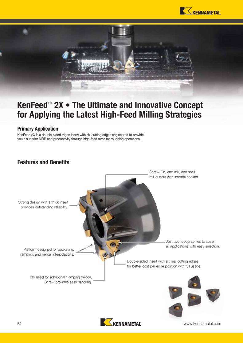
Primary ApplicationKenFeed 2X is a double-sided trigon insert with six cutting edges engineered to provide you a superior MRR and productivity through high-feed rates for roughing operations.
Strong design with a thick insertprovides outstanding reliability.
Platform designed for pocketing,ramping, and helical interpolations.
No need for additional clamping device. Screw provides easy handling.
Double-sided insert with six real cutting edgesfor better cost per edge position with full usage.
Just two topographies to cover all applications with easy selection.
Screw-On, end mill, and shell mill cutters with internal coolant.
KenFeed™ 2X • The Ultimate and Innovative Concept for Applying the Latest High-Feed Milling Strategies
Features and Benefits
www.kennametal.comR2
KM_Master12_R002_R003_METRIC_EN.qxp:Layout 1 3/7/12 9:57 AM Page R2

www.kennametal.com R3
order number catalogue number D1 max D1 D WF G3X L2 Ap1 max Z kg max RPM insert 14113983 KF2X25Z02M12WO09 25 9 21 17 M12 35 1,5 2 0,09 37000 WOEJ090512__4113984 KF2X32Z03M16WO09 32 16 29 22 M16 45 1,5 3 0,22 30900 WOEJ090512__
4113985 KF2X35Z03M16WO09 35 19 29 22 M16 45 1,5 3 0,24 29000 WOEJ090512__4113986 KF2X42Z04M16WO09 42 26 29 22 M16 45 1,5 4 0,28 25800 WOEJ090512__
KenFeed™ 2X Series
• Dramatically improves MRR using the latest milling strategies.
• Engineered to run up to 2,5mm fz.
• Ideal for pocketing, ramping, and helical interpolations. Z-plunge capabilities.
• First choice for deep cavities or from 3 x D.
� Screw-On End Mills • Metric
� Spare Parts
order number catalogue number D1 max D1 D L LBX Ap1 max Z kg max RPM insert 14113987 KF2X25Z02A25WO09L140 25 9 25 140 45 1,5 2 0,46 37000 WOEJ090512__4113988 KF2X25Z02A25WO09L200 25 9 25 200 45 1,5 2 0,68 37000 WOEJ090512__
4113989 KF2X25Z02A25WO09L300 25 9 25 300 45 1,5 2 1,05 37000 WOEJ090512__4113990 KF2X28Z02A25WO09L200 28 11 25 200 45 1,5 2 0,70 34000 WOEJ090512__
4113991 KF2X32Z03A32WO09L150 32 16 32 150 50 1,5 3 0,82 30900 WOEJ090512__4113992 KF2X32Z03A32WO09L200 32 16 32 200 50 1,5 3 1,13 30900 WOEJ090512__
4113993 KF2X32Z03A32WO09L300 32 16 32 300 50 1,5 3 1,75 30900 WOEJ090512__4113994 KF2X35Z03A32WO09L200 35 19 32 200 45 1,5 3 1,16 29000 WOEJ090512__
� End Mills • Metric
Screw-On End Mills • End Mills • WOEJ09...
D1 maxinsert screw Nm
Torx Plus driver
25 MS2235 1,0 DT8IP28 MS2235 1,0 DT8IP
32 MS2235 1,0 DT8IP35 MS2235 1,0 DT8IP
42 MS2235 1,0 DT8IP
Copy
Mill
s
KM_Master12_R002_R003_METRIC_EN.qxp:Layout 1 3/7/12 9:58 AM Page R3
www.kennametal.comR4
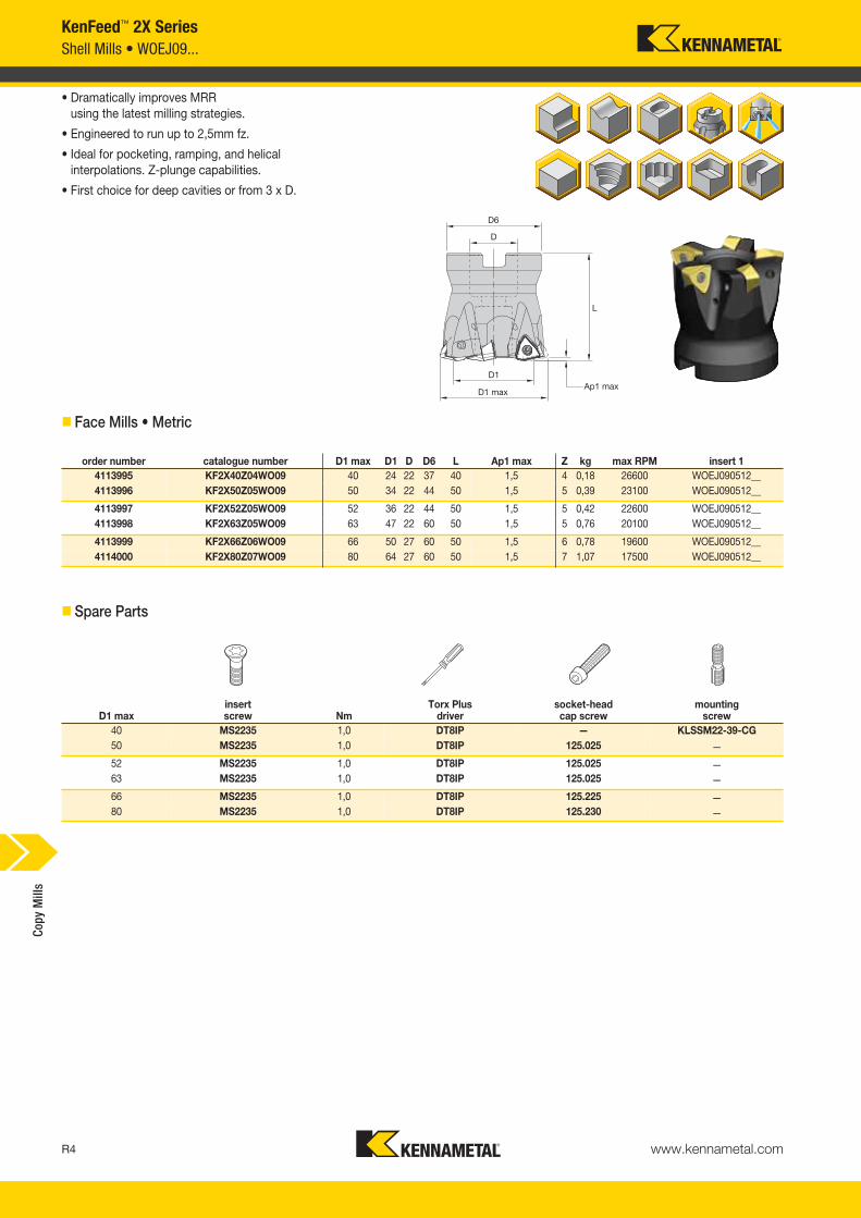
KenFeed™ 2X SeriesShell Mills • WOEJ09...
• Dramatically improves MRR using the latest milling strategies.
• Engineered to run up to 2,5mm fz.
• Ideal for pocketing, ramping, and helical interpolations. Z-plunge capabilities.
• First choice for deep cavities or from 3 x D.
� Face Mills • Metric
order number catalogue number D1 max D1 D D6 L Ap1 max Z kg max RPM insert 14113995 KF2X40Z04WO09 40 24 22 37 40 1,5 4 0,18 26600 WOEJ090512__4113996 KF2X50Z05WO09 50 34 22 44 50 1,5 5 0,39 23100 WOEJ090512__
4113997 KF2X52Z05WO09 52 36 22 44 50 1,5 5 0,42 22600 WOEJ090512__4113998 KF2X63Z05WO09 63 47 22 60 50 1,5 5 0,76 20100 WOEJ090512__
4113999 KF2X66Z06WO09 66 50 27 60 50 1,5 6 0,78 19600 WOEJ090512__4114000 KF2X80Z07WO09 80 64 27 60 50 1,5 7 1,07 17500 WOEJ090512__
� Spare Parts
D1 maxinsert screw Nm
Torx Plus driver
socket-headcap screw
mountingscrew
40 MS2235 1,0 DT8IP — KLSSM22-39-CG50 MS2235 1,0 DT8IP 125.025 —
52 MS2235 1,0 DT8IP 125.025 —63 MS2235 1,0 DT8IP 125.025 —
66 MS2235 1,0 DT8IP 125.225 —80 MS2235 1,0 DT8IP 125.230 —
Copy
Mill
s
KM_Master12_R004_R005_METRIC_EN.qxp:Layout 1 3/7/12 9:56 AM Page R4

www.kennametal.com R5
KenFeed™ 2X Series
� Insert Selection Guide
Indexable Inserts • WOEJ09....
• Double-sided insert with six cutting edges.
• Unique and strong insert design that enables high-feed conditions, up to 2,5mm fz.
• HD geometry is the first choice for steels, high-strength steels, and cast iron.
• GD provides lower cutting forces, first choice for soft materials.
WOEJ-GD WOEJ-HD
� first choice� alternate choice
� WOEJ-GD and -HD
MaterialGroup
Light Machining General Purpose Heavy MachiningGeometry Grade Geometry Grade Geometry Grade
P1–P2 .S..GD KC522M .S..GD KCPK30 .S..GD KCPK30P3–P4 .S..HD KC522M .S..HD KCPK30 .S..HD KCPK30P5–P6 .S..HD KC522M .S..HD KCPK30 .S..HD KCPK30M1–M2 .S..GD KC522M .S..GD KC725M .S..GD KC725M
M3 .S..GD KC725M .S..GD KCPK30 .S..HD KCPK30K1– K2 .S..HD KCK15 .S..HD KCK15 .S..HD KCPK30
K3 .S..HD KCK15 .S..HD KCK15 .S..HD KCPK30N1–N2 — — — — — —
N3 — — — — — —S1–S2 .S..GD KC522M .S..GD KC725M — —
S3 .S..GD KC725M .S..GD KC725M — —S4 .S..GD KC725M .S..GD KC725M — —H1 .S..HD KC522M — — — —
P � � �
M � � �
K � � �
NS � �
H �
catalogue number D Rεε Scutting edges K
C52
2MK
C72
5MK
CK
15K
CP
K30
WOEJ090512SRGD 8,90 1,20 5,40 6 � � �
WOEJ090512SRHD 8,90 1,20 5,50 6 � � � �
Inserts
Copy
Mill
s
KM_Master12_R004_R005_METRIC_EN.qxp:Layout 1 3/7/12 9:56 AM Page R5

www.kennametal.comR6
KenFeed™ 2X SeriesRecommended Starting Speeds and Feeds
� Recommended Starting Speeds [m/min]
NOTE: FIRST choice starting speeds are in bold type.As the average chip thickness increases, the speed should be decreased.
NOTE: Use “Light Machining” values as starting feed rate.
MaterialGroup KC522M KC725M KCK15 KCPK30
P
1 395 345 325 315 275 255 — — — 545 475 4402 330 290 240 260 230 195 — — — 335 305 2753 305 255 215 240 205 170 — — — 305 275 2504 270 225 180 215 180 145 — — — 225 210 1905 225 200 180 180 160 145 — — — 310 275 2556 200 150 120 160 120 95 — — — 190 165 —
M1 245 215 200 205 180 165 — — — 250 220 1902 225 190 160 185 160 130 — — — 225 195 1703 170 145 115 140 120 95 — — — 175 160 140
K1 275 250 220 — — — 505 460 410 355 320 2852 215 195 180 — — — 400 355 330 280 255 2303 180 160 145 — — — 335 300 275 235 210 195
N1 — — — — — — — — — — — —2 — — — — — — — — — — — —
S
1 50 45 35 45 35 30 — — — — — —2 50 45 35 45 35 30 — — — — — —3 60 50 35 55 45 30 — — — — — —4 85 60 45 75 55 35 — — — — — —
H1 145 110 85 — — — — — — — — —2 — — — — — — — — — — — —3 — — — — — — — — — — — —
InsertGeometry
Programmed Feed per Tooth (fz)as a % of Radial Depth of Cut (ae) Insert
Geometry10% 20% 30% 40% 50–100%.S..GD 0,82 1,63 3,33 0,61 1,21 2,43 0,53 1,05 2,11 0,50 0,98 1,97 0,49 0,96 1,92 .S..GD.S..HD 0,82 2,08 3,39 0,61 1,54 2,47 0,53 1,34 2,14 0,50 1,25 2,00 0,49 1,22 1,95 .S..HD
Light Machining
General Purpose
Heavy Machining
Small Ap1 values and higher feed ratesgenerate lower cutting forces versus
traditional milling strategies.
For CAM programming, the loads can beprogrammed as a toroidal tool type by using the Rt value as the insert radius.
Recommended when long overhang is necessary due to lower radial forces.
Maximum L/D ratio of 10 x D.
General Programming Information for Applying KenFeed 2X • IC09
Rt Wt t2.70 8.15 1.15
� Recommended Starting Feeds [mm]
Copy
Mill
s
KM_Master12_R006_R007_METRIC_EN.qxp:Layout 1 3/7/12 9:55 AM Page R6

www.kennametal.com R7
ramp angle
shoulder cut
rampinghelical
interpolation
Ø DH/DH1DH min = Minimum blind hole diameter with helical interpolationDH1 max = Maximum flat-bottom hole diameter
� Maximum Linear Ramping and Helical Interpolation from Solid
cuttertype catalogue number
recommendedramping angle(for continuous
ramping process)
max ramp anglewhen Ap max
(not for continuousramping process)
max ramp angle for 360° helicalinterpolation
min holediameter (DH min)
max flat-bottomhole diameter
(DH1 max)max diameter
(no flat bottom)Screw-On KF2X2X25Z02M12WO09 3.6° 5.4° 3.1° 26,5 33,7 50
KF2X32Z03M16WO09 1.8° 2.7° 1.7° 41,2 48,4 64
KF2X35Z03M16WO09 1.6° 2.4° 1.4° 46,8 54,0 70KF2X42Z04M16WO09 1.2° 1.9° 0.8° 68,7 75,9 84
End Mills KF2X25Z02A25WO09L140 3.6° 5.4° 3.1° 26,5 33,7 50KF2X25Z02A25WO09L200 3.6° 5.4° 3.1° 26,5 33,7 50
KF2X25Z02A25WO09L300 3.6° 5.4° 3.1° 26,5 33,7 50KF2X28Z02A25WO09L200 3.1° 4.6° 2.5° 31,6 38,8 56
KF2X32Z03A32WO09L150 1.8° 2.7° 1.7° 41,2 48,4 64KF2X32Z03A32WO09L200 1.8° 2.7° 1.7° 41,2 48,4 64
KF2X32Z03A32WO09L300 1.8° 2.7° 1.7° 41,2 48,4 64KF2X35Z03A32WO09L200 1.6° 2.4° 1.4° 46,8 54,0 70
Face Mills KF2X40Z04WO09 1.3° 2.0° 1.2° 56,4 63,6 80KF2X50Z05WO09 1.0° 1.5° 0.8° 76,7 83,9 100
KF2X52Z05WO09 1.0° 1.4° 0.8° 80,7 87,9 104KF2X63Z05WO09 0.8° 1.2° 0.6° 102,7 109,9 126
KF2X66Z06WO09 0.7° 1.1° 0.5° 108,7 115,9 132KF2X80Z07WO09 0.6° 0.9° 0.4° 136,6 143,8 160
KenFeed™ 2X SeriesApplication Data
Copy
Mill
s
KM_Master12_R006_R007_METRIC_EN.qxp:Layout 1 3/7/12 9:55 AM Page R7

Primary ApplicationRoughing operations through the latest milling strategies up to 55 HRC. Specially suited for small parts or machines with lower power capacity. The KenFeed Mini delivers higher productivity with reduced tooling costs.
Platform designed for pocketing, ramping, and helical interpolations.
Strong design capacity tosupport higher cutting forces
and unstable situations.
Insert and body design with superior copy milling capabilities enable us to run thecutter with true ramping, profiling, and pocketing capabilities.
Just two topographies to cover all applications with easy selection.
Screw-On and shell mill cutters with internal coolant. Coolant holes: better chip evacuation and higher the tool life.
KenFeed™ Mini • Small High-Feed Milling Cutters for Machining Small and Medium Components
Features and Benefits
www.kennametal.comR8
Excellent runoutaccuracy increases
general performanceand higher tool life.
KM_Master12_R008_R009_METRIC_EN.qxp:Layout 1 3/7/12 9:55 AM Page R8

www.kennametal.com R9
KenFeed™ Mini
• Engineered to use with small machines and/or components using high-feed milling strategies.
• Fine-pitch cutters boost productivity; able to run up to 1,5mm fz.
• Pocketing, ramping, and helical interpolations.
• First choice above 3 x D applications.
� Screw-On End Mills • Metric
� Spare Parts
L
� End Mills • Metric
order number catalogue number D1 max D1 D WF G3X L2 Ap1 max Zmax
ramp angle kg max RPM insert 13331550 16Y02R025M08SWP03 16 11 13 10 M8 25 0,8 2 7.0° 0,03 19900 WP..0302..3651443 20Y03R030M10SWP03 20 14 18 15 M10 30 0,8 3 7.0° 0,06 15900 WP..0302..
4138429 25Y04R035M12SWP03 25 16 21 17 M12 35 1,0 4 3.3° 0,10 12700 WP..0302..4138430 32Y05R043M16SWP03 32 22 29 24 M16 43 1,0 5 2.0° 0,23 9947 WP..0302..
4138431 35Y05R043M16SWP03 35 28 29 24 M16 43 1,0 5 1.8° 0,24 9090 WP..0302..
D1 maxinsert screw Nm
Torx wrench
16 192.416 1,0 FT720 192.416 1,0 FT7
25 192.416 1,0 FT732 192.416 1,0 FT7
35 192.416 1,0 FT7
order number catalogue number D1 max D1 D L L2 Ap1 max Zmax
ramp angle kg max RPM insert 13519052 16Y02R060A16SWP03 16 10 16 110 50 0,8 2 7.0° 0,14 12750 WP..0302..4138432 16Y02R060A16SWP03L150 16 8 16 150 57 1,0 2 7.4° 0,20 15900 WP..0302..
4138443 20Y03R060A20SWP03L110 20 13 20 110 57 1,0 3 4.7° 0,22 15900 WP..0302..4138444 20Y03R060A25SWP03L170 20 12 25 170 55 1,0 3 4.5° 0,53 15600 WP..0302..
4138445 25Y04R060A25SWP03L120 25 18 25 120 57 1,0 4 3.3° 0,39 12700 WP..0302..4138446 25Y04R060A25SWP03L200 25 18 25 200 57 1,0 4 3.3° 0,69 12700 WP..0302..
Screw-On End Mills • Cylindrical End Mills
Copy
Mill
s
KM_Master12_R008_R009_METRIC_EN.qxp:Layout 1 3/7/12 9:55 AM Page R9
www.kennametal.comR10
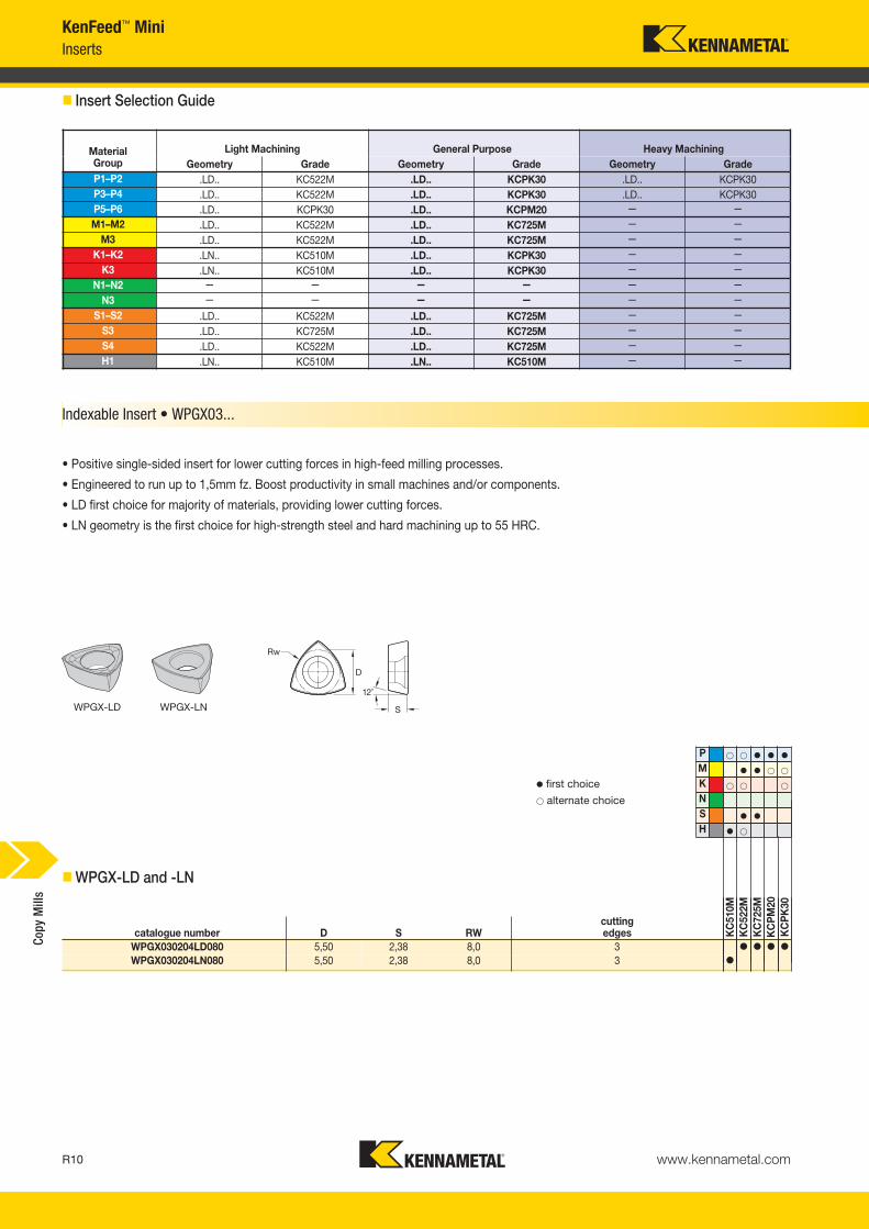
KenFeed™ MiniInserts
� Insert Selection Guide
Indexable Insert • WPGX03...
WPGX-LD WPGX-LN
� first choice� alternate choice
• Positive single-sided insert for lower cutting forces in high-feed milling processes.
• Engineered to run up to 1,5mm fz. Boost productivity in small machines and/or components.
• LD first choice for majority of materials, providing lower cutting forces.
• LN geometry is the first choice for high-strength steel and hard machining up to 55 HRC.
� WPGX-LD and -LN
MaterialGroup
Light Machining General Purpose Heavy MachiningGeometry Grade Geometry Grade Geometry Grade
P1–P2 .LD.. KC522M .LD.. KCPK30 .LD.. KCPK30P3–P4 .LD.. KC522M .LD.. KCPK30 .LD.. KCPK30P5–P6 .LD.. KCPK30 .LD.. KCPM20 — — M1–M2 .LD.. KC522M .LD.. KC725M — —
M3 .LD.. KC522M .LD.. KC725M — — K1–K2 .LN.. KC510M .LD.. KCPK30 — —
K3 .LN.. KC510M .LD.. KCPK30 — — N1–N2 — — — — — —
N3 — — — — — — S1–S2 .LD.. KC522M .LD.. KC725M — —
S3 .LD.. KC725M .LD.. KC725M — — S4 .LD.. KC522M .LD.. KC725M — — H1 .LN.. KC510M .LN.. KC510M — —
P � � � � �
M � � � �
K � � �
NS � �
H � �
catalogue number D S RWcutting edges K
C51
0MK
C52
2MK
C72
5MK
CP
M20
KC
PK
30
WPGX030204LD080 5,50 2,38 8,0 3 � � � �
WPGX030204LN080 5,50 2,38 8,0 3 �
Copy
Mill
s
KM_Master12_R010_R011_METRIC_EN.qxp:Layout 1 3/7/12 9:56 AM Page R10

www.kennametal.com R11
KenFeed™ MiniRecommended Starting Speeds and Feeds
� Recommended Starting Speeds [m/min]
NOTE: FIRST choice starting speeds are in bold type.As the average chip thickness increases, the speed should be decreased.
NOTE: Use “Light Machining” values as starting feed rate.
MaterialGroup KC510M KC522M KC725M KCPM20 KCPK30
P
1 — — — 395 345 325 315 275 255 660 580 535 545 475 4402 — — — 330 290 240 260 230 195 410 370 330 335 305 2753 — — — 305 255 215 240 205 170 370 330 305 305 275 2504 295 240 200 270 225 180 215 180 145 275 255 230 225 210 1905 — — — 225 200 180 180 160 145 330 300 275 310 275 2556 — — — 200 150 120 160 120 95 230 200 175 190 165 —
M1 — — — 245 215 200 205 180 165 270 240 205 250 220 190
2 — — — 225 190 160 185 160 130 245 215 190 225 195 170
3 — — — 170 145 115 140 120 95 195 175 150 175 160 140
K1 350 315 285 275 250 220 — — — 435 390 350 355 320 2852 275 250 230 215 195 180 — — — 345 310 280 280 255 2303 235 205 190 180 160 145 — — — 290 255 240 235 210 195
N1 — — — — — — — — — — — — — — — 2 — — — — — — — — — — — — — — —
S
1 — — — 50 45 35 45 35 30 — — — — — — 2 — — — 50 45 35 45 35 30 — — — — — — 3 — — — 60 50 35 55 45 30 — — — — — — 4 — — — 85 60 45 75 55 35 — — — — — —
H1 190 155 110 145 110 85 — — — — — — — — — 2 — — — — — — — — — — — — — — — 3 — — — — — — — — — — — — — — —
InsertGeometry
Programmed Feed per Tooth (fz)as a % of Radial Depth of Cut (ae) Insert
Geometry10% 20% 30% 40% 50–100%.LD.. 0,66 1,67 2,70 0,49 1,23 1,98 0,43 1,07 1,72 0,40 1,00 1,60 0,39 0,98 1,57 .LD...LN.. 0,66 1,67 2,70 0,49 1,23 1,98 0,43 1,07 1,72 0,40 1,00 1,60 0,39 0,98 1,57 .LN..
Light Machining
General Purpose
Heavy Machining
General Programming Information for Applying KenFeed Mini
Small Ap1 values and higher feed ratesgenerate lower cutting forces versus
traditional milling strategies.
For CAM programming, the loads canbe programmed as a toroidal tool type
by using the Rt value as the insert radius.
Rt Wt t1.00 2.40 0.40
� Recommended Starting Feeds [mm]
Copy
Mill
s
KM_Master12_R010_R011_METRIC_EN.qxp:Layout 1 3/7/12 9:56 AM Page R11

Features and Benefits
Rodeka™ • The New Round Insert Generation
Primary ApplicationKennametal introduces a new and revolutionary double-sided round milling insert capable to run in multiple types of milling operations and workpiece materials, providing the latest double-sided insert technology to boost your productivity with the most efficient cost per edge.
www.kennametal.comR12
Double-sided insert with up to12 cutting edges for a moreproductive cutting process.
Higher clearance in bodies topermit pocketing, profiling,
and 5-axis machining.
Three insert and topography styles to cover any type of component and application.
Unique anti-rotation feature for excellent stability with higher feed rates and cutting forces. User-friendly insert rotation.
Screw-On, end mill, and shellmill cutters with internal coolant.
To learn more, scan here. For instructions on how to scan, please see page xxix.
KM_Master12_R012_R013_METRIC_EN.qxp:Layout 1 3/7/12 9:55 AM Page R12
www.kennametal.com R13
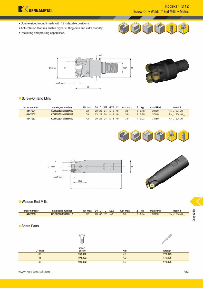
order number catalogue number D1 max D1 D WF G3X L2 Ap1 max Z kg max RPM insert 14147001 KDR32Z03M16RN12 32 20 29 24 M16 40 3,0 3 0,18 39160 RN_J1204M0__4147002 KDR35Z03M16RN12 35 23 29 24 M16 40 3,0 3 0,20 37440 RN_J1204M0__
4147033 KDR42Z04M16RN12 42 30 29 24 M16 40 3,0 4 0,23 34180 RN_J1204M0__
Rodeka™ IC 12
• Double-sided round inserts with 12 indexable positions.
• Anti-rotation features enable higher cutting data and extra stability.
• Pocketing and profiling capabilities.
� Screw-On End Mills
order number catalogue number D1 max D1 D L LBX Ap1 max Z kg max RPM insert 14147035 KDR32Z03B32RN12 32 20 32 125 40 3,0 3 0,64 39160 RN_J1204M0__
� Weldon End Mills
Screw-On • Weldon® End Mills • Metric
Copy
Mill
s
� Spare Parts
D1 maxinsert screw Nm wrench
32 193.492 4,0 170.02535 193.492 4,0 170.025
42 193.492 4,0 170.025
KM_Master12_R012_R013_METRIC_EN.qxp:Layout 1 3/7/12 9:55 AM Page R13

www.kennametal.comR14
order number catalogue number D1 max D1 D L LBX Ap1 max Z kg max RPM insert 14147038 KDR32Z02A32RN12L250 32 20 32 250 40 3,0 2 1,41 39160 RN_J1204M0__4147037 KDR32Z03A32RN12L200 32 20 32 200 40 3,0 3 1,10 39160 RN_J1204M0__
Rodeka™ IC 12Cylindrical End Mills • Metric
• Double-sided round insert with 12 indexable positions.
• Anti-rotation feature enable higher cutting forces and extra stability.
• Pocketing and profiling capabilities.
� Cylindrical End Mills
� Spare Parts
D1 maxinsert screw Nm wrench
32 193.492 4,0 170.02535 193.492 4,0 170.025
42 193.492 4,0 170.025
Copy
Mill
s
KM_Master12_R014_R015_METRIC_EN.qxp:Layout 1 3/7/12 9:55 AM Page R14

www.kennametal.com R15
order number catalogue number D1 max D1 D D6 L Ap1 max Z kg max RPM insert 14147039 KDR40Z04S16RN12 40 28 16 38 40 3,0 4 0,21 35020 RN_J1204M0__4147040 KDR50Z04S22RN12 50 38 22 42 40 3,0 4 0,81 31330 RN_J1204M0__
4147041 KDR50Z05S22RN12 50 38 22 42 40 3,0 5 0,81 31330 RN_J1204M0__4147042 KDR52Z05S22RN12 52 40 22 49 50 3,0 5 0,81 30720 RN_J1204M0__
4147043 KDR63Z05S22RN12 63 51 22 49 50 3,0 5 0,81 27910 RN_J1204M0__4147044 KDR63Z07S22RN12 63 51 22 49 50 3,0 7 0,81 27910 RN_J1204M0__
4147045 KDR66Z07S27RN12 66 54 27 60 50 3,0 7 0,81 27260 RN_J1204M0__4147046 KDR80Z06S27RN12 80 68 27 60 50 3,0 6 1,07 24760 RN_J1204M0__
4147047 KDR80Z08S27RN12 80 68 27 60 50 3,0 8 0,81 24760 RN_J1204M0__4147048 KDR100Z07S32RN12 100 88 32 78 50 3,0 7 1,57 22150 RN_J1204M0__
4147049 KDR100Z09S32RN12 100 88 32 78 50 3,0 9 1,56 22150 RN_J1204M0__
D1 maxinsert screw Nm
low-headcap screw
socket-headcap screw
coolant lock screw assembly wrench
40 193.492 4,0 — MS1294 — 170.02550 193.492 4,0 MS1336 — — 170.025
52 193.492 4,0 — MS1242 — 170.02563 193.492 4,0 — MS1242 — 170.025
66 193.492 4,0 — MS2038 — 170.02580 193.492 4,0 — MS2038 — 170.025
100 193.492 4,0 — — MS2195C 170.025
Rodeka™ IC 12Shell Mills • Metric
• Double-sided round inserts with 12 indexable positions.
• Anti-rotation features enable higher cutting data and extra stability.
• Pocketing and profiling capabilities.
� Shell Mills
� Spare Parts
Copy
Mill
s
KM_Master12_R014_R015_METRIC_EN.qxp:Layout 1 3/7/12 9:55 AM Page R15

www.kennametal.comR16
Rodeka™ IC 12Inserts
� Insert Selection Guide
MaterialGroup
Light Machining General Purpose Heavy MachiningGeometry Grade Geometry Grade Geometry Grade
P1–P2 .E..LD KCPK30 .S..GD KCPK30 .S..HD KCPK30P3–P4 .S..GD KC522M .S..HD KCPM20 .S..HD KCPK30P5–P6 .S..GD KC522M .S..GD KCPK30 .S..HD KCPM20M1–M2 .E..LD KC522M .E..LD KC522M .S..GD KC725M
M3 .E..LD KC522M .S..GD KCPK30 .S..HD KCPK30K1–K2 .S..HD KCK15 .S..HD KCK15 .S..HD KCPK30
K3 .S..HD KCK15 .S..HD KCK15 .S..HD KCPK30N1–N2 .F..LDJ KC422M .F..LDJ KC422M — —
N3 .F..LDJ KC422M .F..LDJ KC422M — — S1–S2 .E..LD KC725M .S..GD KC725M .S..HD KC725M
S3 .E..LD KC725M .S..GD KC725M .S..HD KC725MS4 .E..LD KC725M .E..LD KC725M .S..GD KC725MH1 .S..GD KC522M .S..HD KCPM20 — —
P � � � �
M � � � �
K � � �
N �
S � �
H � �
Indexable Inserts • RNGJ12....
• -FLDJ geometry is for non-ferrous metals.
• -LD geometry is the first choice for stainless steel and titanium machining at lower cutting forces.
• -GD geometry is for general use in steel and for stainless steel.
• -HD geometry is the first choice for heavy machining, high-strength steel and cast iron.
RNGJ-LD/-LDJ RNGJ-GD RNGJ-HD
� first choice� alternate choice
� RNGJ-LD/-LDJ
� RNGJ-GD
� RNGJ-HD
catalogue number D S hmcuttingedges K
C42
2MK
C52
2MK
C72
5MK
CK
15K
CP
M20
KC
PK
30
RNGJ1204M0ELD 12,00 4,75 0,04 12 � � �
RNGJ1204M0FLDJ 12,00 4,75 0,04 12 �
catalogue number D S hmcuttingedges K
C42
2MK
C52
2MK
C72
5MK
CK
15K
CP
M20
KC
PK
30
RNGJ1204M0SGD 12,00 4,75 0,09 12 � � �
catalogue number D S hmcuttingedges K
C42
2MK
C52
2MK
C72
5MK
CK
15K
CP
M20
KC
PK
30
RNGJ1204M0SHD 12,00 4,75 0,19 12 � � � �
Copy
Mill
s
KM_Master12_R016_R017_METRIC_EN.qxp:Layout 1 3/7/12 9:57 AM Page R16

www.kennametal.com R17
Rodeka™ IC 12
NOTE: FIRST choice starting speeds are in bold type.As the average chip thickness increases, the speed should be decreased.
MaterialGroup KC422M KC522M KC725M KCK15 KCPM20 KCPK30
P
1 — — — 395 345 325 315 275 255 — — — 310 580 535 545 475 4402 — — — 330 290 240 260 230 195 — — — 275 370 330 335 305 2753 — — — 305 255 215 240 205 170 — — — 240 330 305 305 275 2504 — — — 270 225 180 215 180 145 — — — 175 255 230 225 210 1905 — — — 225 200 180 180 160 145 — — — 170 300 275 310 275 2556 — — — 200 150 120 160 120 95 — — — 105 200 175 190 165 —
M1 — — — 245 215 200 205 180 165 — — — 190 240 205 250 220 1902 — — — 225 190 160 185 160 130 — — — 170 215 190 225 195 1703 — — — 170 145 115 140 120 95 — — — 105 175 150 175 160 140
K1 — — — 275 250 220 — — — 505 460 410 220 390 350 355 320 2852 — — — 215 195 180 — — — 400 355 330 175 310 280 280 255 2303 — — — 180 160 145 — — — 335 300 275 155 255 240 235 210 195
N1–2 1285 1135 1050 — — — — — — — — — — — — — — —3 1135 1050 915 — — — — — — — — — — — — — — —
S
1 — — — 50 45 35 45 35 30 — — — — — — — — —2 — — — 50 45 35 45 35 30 — — — — — — — — —3 — — — 60 50 35 55 45 30 — — — — — — — — —4 — — — 85 60 45 75 55 35 — — — — — — — — —
H 1 — — — 145 110 85 — — — — — — 170 140 115 — — —
InsertGeometry
Programmed Feed per Tooth (fz)as a % of Radial Depth of Cut (ae) Insert
Geometry10% 20% 30% 40% 50%–100%.F..LDJ 0,10 0,18 0,31 0,08 0,13 0,23 0,07 0,11 0,20 0,06 0,11 0,19 0,06 0,11 0,18 .F..LDJ.E..LD 0,10 0,18 0,31 0,08 0,13 0,23 0,07 0,11 0,20 0,06 0,11 0,19 0,06 0,11 0,18 .E..LD.S..GD 0,24 0,40 0,71 0,18 0,30 0,53 0,16 0,26 0,46 0,15 0,25 0,43 0,14 0,24 0,42 .S..GD.S..HD 0,39 0,58 0,87 0,29 0,43 0,65 0,25 0,38 0,57 0,24 0,35 0,53 0,23 0,35 0,52 .S..HD
InsertGeometry
Programmed Feed per Tooth (fz)as a % of Radial Depth of Cut (ae) Insert
Geometry10% 20% 30% 40% 50%–100%.F..LDJ 0,14 0,23 0,40 0,10 0,17 0,30 0,09 0,15 0,26 0,08 0,14 0,25 0,08 0,14 0,24 .F..LDJ.E..LD 0,14 0,23 0,40 0,10 0,17 0,30 0,09 0,15 0,26 0,08 0,14 0,25 0,08 0,14 0,24 .E..LD.S..GD 0,31 0,53 0,93 0,23 0,40 0,69 0,20 0,34 0,60 0,19 0,32 0,56 0,19 0,32 0,55 .S..GD.S..HD 0,51 0,76 1,15 0,38 0,57 0,85 0,33 0,50 0,74 0,31 0,46 0,69 0,30 0,45 0,68 .S..HD
InsertGeometry
Programmed Feed per Tooth (fz)as a % of Radial Depth of Cut (ae) Insert
Geometry10% 20% 30% 40% 50%–100%.F..LDJ 0,19 0,32 0,55 0,14 0,24 0,41 0,12 0,21 0,36 0,11 0,19 0,34 0,11 0,19 0,33 .F..LDJ.E..LD 0,19 0,32 0,55 0,14 0,24 0,41 0,12 0,21 0,36 0,11 0,19 0,34 0,11 0,19 0,33 .E..LD.S..GD 0,43 0,72 1,28 0,32 0,54 0,95 0,28 0,47 0,82 0,26 0,44 0,77 0,25 0,43 0,75 .S..GD.S..HD 0,69 1,04 1,58 0,52 0,78 1,17 0,45 0,68 1,02 0,42 0,63 0,95 0,41 0,62 0,93 .S..HD
NOTE: Use “Light Machining” values as starting feed rate.
� Recommended Starting Speeds [m/min]
� Recommended Starting Feeds [mm] Light Machining
General Purpose
Heavy Machining
Recommended Starting Speeds and Feeds
At 0,75 Axial Depth of Cut (ap)
At 1,50 Axial Depth of Cut (ap)
At 3,00 Axial Depth of Cut (ap)
Copy
Mill
s
KM_Master12_R016_R017_METRIC_EN.qxp:Layout 1 3/7/12 9:57 AM Page R17

www.kennametal.comR18
Rodeka 8 Turbine Blade Version Revolutionary double-sided round insert engineered for turbine blade machining. Special geometries, insert styles, and dedicated cutter bodies have been developed to serve this demanding application.
Four indexes per side, in total eightcutting edges. With higher Ap
capabilities, up to 6mm.
Specific high positive geometries
with improved chip forming and
higher tool life.
Insert location twisted by 45°
between top and bottom side
for equal performance over all
eight cutting edges.
Unique anti-rotation feature with
higher contact area for excellent
stability, allowing higher feed rates.
Power Plant
Rodeka 8
Turbine Blade
Steam Turbine
Rodeka™ 8, IC 12Co
py M
ills
KM_Master12_R018_R019_METRIC_EN.qxp:Layout 1 3/28/12 10:59 AM Page R18

catalogue number
RNGJ1204M0ENLDJX
RNGJ1204M0ENLDX
RNGJ1204M0SNGDJXRNGJ1204M0SNGDX
www.kennametal.com R19
P
M
S
P
M
S
-LD -GD
Light/Medium Machining
First choice for stainless steel and titanium machining.
Medium/Heavy Machining
First choice for medium/heavy operations. Forged blades
or “bad skin”.
MM# catalogue number D1 max D1 D D6 L Ap1 max Z5104420 KDR40Z04S16RN12X 40 28 16 38 40 6 45104421 KDR50Z05S22RN12X 50 38 22 42 40 6 5
5104422 KDR50Z05S22RN12XL 50 38 22 49 40 6 5
5104423 KDR52Z05S22RN12X 52 40 22 42 40 6 5
5104424 KDR63Z06S22RN12X 63 51 22 49 40 6 6
5104425 KDR66Z06S27RN12X 66 54 27 60 40 6 6
5104426 KDR80Z07S27RN12X 80 68 27 60 50 6 7
KC
522M
KC
725M
KC
MP
30
P � � �
M � � �
KNS � � �
H
� first choice� alternate choice
� �
�
� �
�
� Shell Mills
� Indexable Inserts
Product OfferingRodeka™ 8, IC 12
Copy
Mill
s
KM_Master12_R018_R019_METRIC_EN.qxp:Layout 1 3/28/12 10:59 AM Page R19

KDM • Strong, Flexible, and Highly Accurate
Primary ApplicationRoughing and finishing milling operations on complex parts. First choice for die and mould industry up to 55 HRC.
Features and Benefits
Platform Features• Big draft clearance angle to improve the pocketing operations performance.
• Big clearance area in the bottom, superior ramping, and helical values.
• High accuracy and tight runout.
Value Proposition• Real HSM capabilities: more teeth and close accuracy.
• Strongest and most rigid design for roughing operations.
• Addressed to the die and mould and general engineering markets, mainly.
• PSTS and ground inserts are offered through different inserts sizes.
• Shell mill, Weldon® and straight shank, and Screw-On body cutters.
• Multiple grades available; wide range of workpieces and applications.
www.kennametal.comR20
KM_Master12_R020_R021_METRIC_EN.qxp:Layout 1 3/7/12 9:56 AM Page R20
www.kennametal.com R21
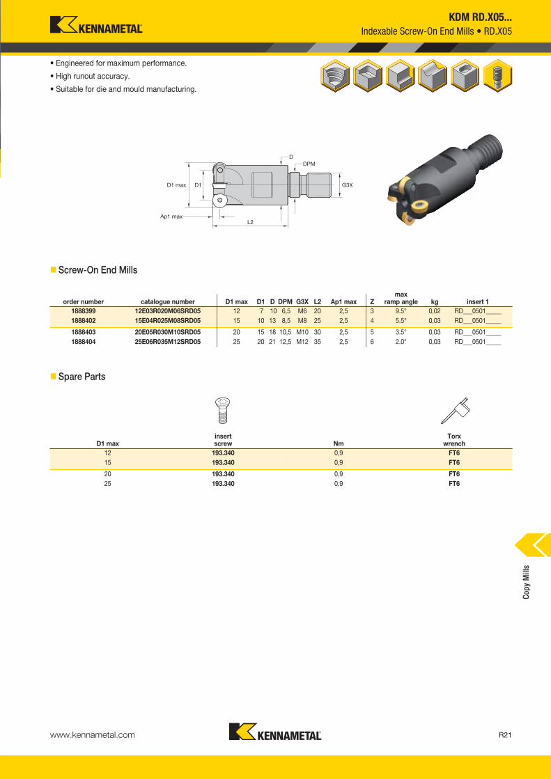
KDM RD.X05...Indexable Screw-On End Mills • RD.X05
• Engineered for maximum performance.
• High runout accuracy.
• Suitable for die and mould manufacturing.
� Screw-On End Mills
order number catalogue number D1 max D1 D DPM G3X L2 Ap1 max Zmax
ramp angle kg insert 11888399 12E03R020M06SRD05 12 7 10 6,5 M6 20 2,5 3 9.5° 0,02 RD___0501_____1888402 15E04R025M08SRD05 15 10 13 8,5 M8 25 2,5 4 5.5° 0,03 RD___0501_____
1888403 20E05R030M10SRD05 20 15 18 10,5 M10 30 2,5 5 3.5° 0,03 RD___0501_____1888404 25E06R035M12SRD05 25 20 21 12,5 M12 35 2,5 6 2.0° 0,03 RD___0501_____
D1 maxinsert screw Nm
Torx wrench
12 193.340 0,9 FT615 193.340 0,9 FT6
20 193.340 0,9 FT625 193.340 0,9 FT6
� Spare Parts
Copy
Mill
s
KM_Master12_R020_R021_METRIC_EN.qxp:Layout 1 3/7/12 9:56 AM Page R21

� RDHX-LN
www.kennametal.comR22
KDM RD.X05...Inserts
� Insert Selection Guide
MaterialGroup
Light Machining General Purpose Heavy MachiningGeometry Grade Geometry Grade Geometry Grade
P1–P2 .E..LN KC522M .E..LN KC522M .E..LN KC725MP3–P4 .E..LN KC522M .E..LN KC522M .E..LN KC725MP5–P6 .E..LN KC522M .E..LN KC522M .E..LN KC725MM1–M2 .E..LN KC522M .E..LN KC725M .E..LN KC725M
M3 .E..LN KC522M .E..LN KC725M .E..LN KC725MK1–K2 .E..LN KC510M .E..LN KC510M .E..LN KC510M
K3 .E..LN KC510M .E..LN KC510M .E..LN KC510MN1–N2 — — — — — —
N3 — — — — — —S1–S2 — — — — — —
S3 — — — — — —S4 — — — — — —H1 .E..LN KC510M .E..LN KC510M — —
P � � �
M � �
K � �
NSH � �
catalogue number D S hm KC
510M
KC
522M
KC
725M
RDHX0501M0ELN 5,00 1,50 0,04 � � �
Indexable Round Inserts • RD.X05...
RDHX-LN
� first choice� alternate choice
Copy
Mill
s
KM_Master12_R022_R023_METRIC_EN.qxp:Layout 1 3/7/12 9:57 AM Page R22

www.kennametal.com R23
KDM RD.X05...Inserts
MaterialGroup KC510M KC522M KC725M
P
1 — — — 395 345 325 315 275 2552 — — — 330 290 240 260 230 1953 — — — 305 255 215 240 205 1704 295 240 200 270 225 180 215 180 1455 — — — 225 200 180 180 160 1456 — — — 200 150 120 160 120 95
M1 — — — 245 215 200 205 180 1652 — — — 225 190 160 185 160 1303 — — — 170 145 115 140 120 95
K1 350 315 — 275 250 220 — — —
2 275 250 230 215 195 180 — — —3 235 205 190 180 160 145 — — —
N1–2 770 685 630 — — — — — —3 — — — — — — — — —
S
1 — — — — — — — — —2 — — — — — — — — —3 — — — — — — — — —4 — — — — — — — — —
H 1 190 155 110 145 110 85 — — —
NOTE: FIRST choice starting speeds are in bold type.As the average chip thickness increases, the speed should be decreased.
InsertGeometry
Programmed Feed per Tooth (fz)as a % of Radial Depth of Cut (ae) Insert
Geometry10% 20% 30% 40% 50–100%.E..LN 0,09 0,27 0,67 0,07 0,20 0,50 0,06 0,17 0,44 0,06 0,16 0,41 0,06 0,16 0,40 .E..LN
InsertGeometry
Programmed Feed per Tooth (fz)as a % of Radial Depth of Cut (ae) Insert
Geometry10% 20% 30% 40% 50–100%.E..LN 0,12 0,33 0,84 0,09 0,25 0,63 0,08 0,22 0,55 0,07 0,20 0,51 0,07 0,20 0,50 .E..LN
InsertGeometry
Programmed Feed per Tooth (fz)as a % of Radial Depth of Cut (ae) Insert
Geometry10% 20% 30% 40% 50–100%.E..LN 0,16 0,45 1,12 0,12 0,33 0,84 0,10 0,29 0,73 0,10 0,27 0,68 0,09 0,27 0,67 .E..LN
InsertGeometry
Programmed Feed per Tooth (fz)as a % of Radial Depth of Cut (ae) Insert
Geometry10% 20% 30% 40% 50–100%.E..LN 0,22 0,62 1,56 0,16 0,46 1,15 0,14 0,40 1,00 0,13 0,37 0,94 0,13 0,37 0,92 .E..LN
NOTE: Use “Light Machining” values as starting feed rate.
Light Machining
General Purpose
Heavy Machining
� Recommended Starting Speeds [m/min]
� Recommended Starting Feeds [mm]
At 2,50 Axial Depth of Cut (ap)
At 1,00 Axial Depth of Cut (ap)
At 0,50 Axial Depth of Cut (ap)
At 0,25 Axial Depth of Cut (ap)
Copy
Mill
s
KM_Master12_R022_R023_METRIC_EN.qxp:Layout 1 3/7/12 9:57 AM Page R23

www.kennametal.comR24
• Engineered for high performance.
• High runout accuracy.
• Suitable for die and mould manufacturing.
� Screw-On End Mills • RD.X07 Inserts
� Spare Parts
D1 maxinsert screw Nm
Torx wrench
12 193.364 1,0 FT715 193.341 1,0 FT7
20 193.341 1,0 FT725 193.341 1,0 FT7
30 193.341 1,0 FT735 193.341 1,0 FT7
order number catalogue number D1 max D1 D L L2 L3 Ap1 max Zmax
ramp angle kg insert 11888453 15E02R040B16SRD07 15 8 16 90 40 40 3,5 2 4.5° 0,13 RD_X0702__1888469 15E02R060B16SRD07 15 8 16 110 40 25 3,5 2 4.5° 0,15 RD_X0702__
1888465 15E02R100B20SRD07 15 8 20 152 100 40 3,5 2 4.5° 0,28 RD_X0702__1888463 15E02R120B25SRD07 15 8 25 178 120 40 3,5 2 4.5° 0,45 RD_X0702__
KDM RD.X07...
• Suitable for die and mould manufacturing.
� End Mills with Weldon® Shank • RD.X07 Inserts
Indexable End Mills • Indexable Screw-On End Mills • RD.X07...Co
py M
ills
order number catalogue number D1 max D1 D D2 DPM G3X L2 Ap1 max Zmax
ramp angle kg insert 11888407 12E02R018M06SRD07 12 5 10 11 6,5 M6 18 3,5 2 9.5° 0,02 RD__07T1__1888406 12E02R028M08SRD07 12 5 13 11 8,5 M8 28 3,5 2 9.5° 0,03 RD__0701__
1888409 15E02R023M08SRD07 15 8 13 13 8,5 M8 23 3,5 2 4.5° 0,03 RD__0702__1888410 15E03R023M08SRD07 15 8 13 13 8,5 M8 23 3,5 3 4.5° 0,03 RD__0702__
1888411 20E04R030M10SRD07 20 13 18 18 10,5 M10 30 3,5 4 2.5° 0,07 RD__0702__1888412 25E05R035M12SRD07 25 18 21 21 12,5 M12 35 3,5 5 3.5° 0,11 RD__0702__
1888413 30E05R043M16SRD07 30 23 29 26 17,0 M16 43 3,5 5 5.5° 0,22 RD__0702__1888414 35E06R043M16SRD07 35 28 29 32 17,0 M16 43 3,5 6 4.5° 0,25 RD__0702__
KM_Master12_R024_R025_METRIC_EN.qxp:Layout 1 3/7/12 9:56 AM Page R24
www.kennametal.com R25
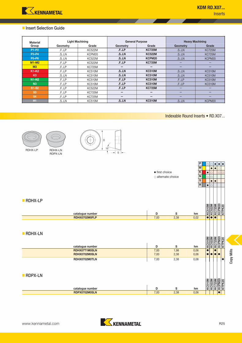
KDM RD.X07...Inserts
� Insert Selection Guide
MaterialGroup
Light Machining General Purpose Heavy MachiningGeometry Grade Geometry Grade Geometry Grade
P1–P2 .F..LP KC522M .F..LP KC725M .S..LN KC725MP3–P4 .S..LN KCPM20 .S..LN KC522M .S..LN KC725MP5–P6 .S..LN KC522M .S..LN KCPM20 .S..LN KCPM20M1–M2 .F..LP KC522M .F..LP KC725M — —
M3 .F..LP KC725M — — — —K1–K2 .F..LP KC510M .S..LN KC510M .S..LN KC510M
K3 .S..LN KC510M .S..LN KC510M .S..LN KC510MN1–N2 .F..LP KC510M .F..LP KC510M .F..LP KC510M
N3 .F..LP KC510M .F..LP KC510M .F..LP KC510MS1–S2 .F..LP KC522M .F..LP KC725M — —
S3 .F..LP KC725M — — — —S4 .F..LP KC725M — — — —H1 .S..LN KC510M .S..LN KC510M .S..LN KCPM20
P � � � � �
M � � �
K � � � �
N � �
S � �
H � �
catalogue number D S hm KC
510M
KC
522M
KC
725M
KC
PM
20K
TPK
20
RDHX0702M0FLP 7,00 2,38 0,02 � � �
catalogue number D S hm KC
510M
KC
522M
KC
725M
KC
PM
20K
TPK
20
RDHX07T1M0SLN 7,00 1,98 0,06 � �
RDHX0702M0SLN 7,00 2,38 0,06 � � � �
RDHX0702M0TLN 7,00 2,38 0,08 �
catalogue number D S hm KC
510M
KC
522M
KC
725M
KC
PM
20K
TPK
20
RDPX0702M0SLN 7,00 2,38 0,06 �
RDHX-LP RDHX-LNRDPX-LN
� first choice� alternate choice
� RDHX-LP
� RDHX-LN
� RDPX-LN
Indexable Round Inserts • RD.X07...
Copy
Mill
s
KM_Master12_R024_R025_METRIC_EN.qxp:Layout 1 3/7/12 9:56 AM Page R25

www.kennametal.comR26
Recommended Starting Speeds and Feeds
MaterialGroup KC510M KC522M KC725M KCPM20 KTPK20
P
1 — — — 395 345 325 315 275 255 660 580 535 440 360 3102 — — — 330 290 240 260 230 195 410 370 330 270 225 1903 — — — 305 255 215 240 205 170 370 330 305 245 205 1704 295 240 200 270 225 180 215 180 145 275 255 230 185 160 1305 — — — 225 200 180 180 160 145 330 300 275 255 205 1756 — — — 200 150 120 160 120 95 230 200 175 150 125 —
M1 — — — 245 215 200 205 180 165 270 240 205 285 235 2002 — — — 225 190 160 185 160 130 245 215 190 260 220 1853 — — — 170 145 115 140 120 95 195 175 150 195 160 —
K1 350 315 285 275 250 220 — — — 435 390 350 275 235 1952 275 250 230 215 195 180 — — — 345 310 280 220 180 1603 235 205 190 180 160 145 — — — 290 255 240 185 150 130
N1–2 770 685 630 — — — — — — — — — — — —3 695 640 585 — — — — — — — — — — — —
S
1 — — — 50 45 35 45 35 30 — — — — — —2 — — — 50 45 35 45 35 30 — — — — — —3 — — — 60 50 35 55 45 30 — — — — — —4 — — — 85 60 45 75 55 35 — — — — — —
H 1 190 155 110 145 110 85 — — — 170 140 115 — — —
KDM RD.X07
NOTE: FIRST choice starting speeds are in bold type.As the average chip thickness increases, the speed should be decreased.
InsertGeometry
Programmed Feed per Tooth (fz)as a % of Radial Depth of Cut (ae) Insert
Geometry10% 20% 30% 40% 50–100%.F..LP 0,08 0,13 0,33 0,06 0,10 0,25 0,06 0,09 0,22 0,05 0,08 0,20 0,05 0,08 0,20 .F..LP.S..LN 0,14 0,41 0,68 0,11 0,31 0,51 0,09 0,27 0,44 0,09 0,25 0,41 0,09 0,24 0,41 .S..LN.T..LN 0,17 0,43 0,68 0,13 0,32 0,51 0,11 0,28 0,44 0,10 0,26 0,41 0,10 0,25 0,41 .T..LN
InsertGeometry
Programmed Feed per Tooth (fz)as a % of Radial Depth of Cut (ae) Insert
Geometry10% 20% 30% 40% 50–100%.F..LP 0,10 0,15 0,39 0,07 0,12 0,29 0,06 0,10 0,25 0,06 0,09 0,24 0,06 0,09 0,23 .F..LP.S..LN 0,17 0,47 0,79 0,12 0,35 0,59 0,11 0,31 0,51 0,10 0,29 0,48 0,10 0,28 0,47 .S..LN.T..LN 0,20 0,49 0,79 0,15 0,37 0,59 0,13 0,32 0,51 0,12 0,30 0,48 0,12 0,29 0,47 .T..LN
InsertGeometry
Programmed Feed per Tooth (fz)as a % of Radial Depth of Cut (ae) Insert
Geometry10% 20% 30% 40% 50–100%.F..LP 0,12 0,19 0,48 0,09 0,14 0,36 0,08 0,12 0,31 0,07 0,12 0,29 0,07 0,11 0,29 .F..LP.S..LN 0,21 0,58 0,98 0,15 0,44 0,73 0,13 0,38 0,63 0,13 0,36 0,59 0,12 0,35 0,58 .S..LN.T..LN 0,24 0,61 0,98 0,18 0,45 0,73 0,16 0,40 0,63 0,15 0,37 0,59 0,15 0,36 0,58 .T..LN
InsertGeometry
Programmed Feed per Tooth (fz)as a % of Radial Depth of Cut (ae) Insert
Geometry10% 20% 30% 40% 50–100%.F..LP 0,16 0,26 0,65 0,12 0,19 0,49 0,11 0,17 0,42 0,10 0,16 0,40 0,10 0,16 0,39 .F..LP.S..LN 0,28 0,80 1,33 0,21 0,59 0,99 0,18 0,52 0,86 0,17 0,48 0,81 0,17 0,47 0,79 .S..LN.T..LN 0,33 0,83 1,33 0,25 0,62 0,99 0,22 0,54 0,86 0,20 0,50 0,81 0,20 0,49 0,79 .T..LN
NOTE: Use “Light Machining” values as starting feed rate.
Light Machining
General Purpose
Heavy Machining
� Recommended Starting Speeds [m/min]
� Recommended Starting Feeds [mm]
At 3,50 Axial Depth of Cut (ap)
At 1,75 Axial Depth of Cut (ap)
At 1,00 Axial Depth of Cut (ap)
At 0,50 Axial Depth of Cut (ap)
Copy
Mill
s
KM_Master12_R026_R027_METRIC_EN.qxp:Layout 1 3/28/12 11:21 AM Page R26

www.kennametal.com R27
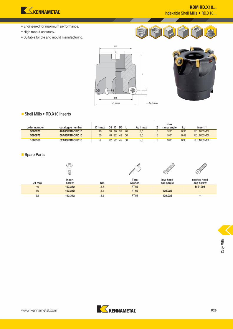
KDM RD.X10...
• Engineered for maximum performance.
• High runout accuracy.
• Suitable for die and mould manufacturing.
� Screw-On End Mills • RD.X10 Inserts
order number catalogue number D1 max D1 D L L3 Ap1 max Zmax
ramp angle kg insert 11888457 25E02R070A25SRD10 25 15 25 180 70 5,0 2 15.0° 0,62 RD_X1003__1888454 32E03R090A32SRD10 32 22 32 200 90 5,0 3 15.0° 0,20 RD_X1003__
• Suitable for die and mould manufacturing.
� End Mills with Cylindrical Shank • RD.X10 Inserts
Indexable Screw-On End Mills • Indexable End Mills • RD.X10...
Copy
Mill
s
order number catalogue number D1 max D1 D D2 DPM G3X L2 Ap1 max Zmax
ramp angle kg insert 11888415 20E02R030M10SRD10 20 10 18 18 10,5 M10 30 5,0 2 15.0° 0,07 RD_X1003__1888416 25E02R035M12SRD10 25 15 21 21 12,5 M12 35 5,0 2 13.5° 0,03 RD_X1003__
1888417 25E03R035M12SRD10 25 15 21 21 12,5 M12 35 5,0 3 13.5° 0,11 RD_X1003__1888418 30E04R043M16SRD10 30 20 29 25 17,0 M16 43 5,0 4 9.0° 0,20 RD_X1003__
1888419 35E04R045M16SRD10 35 25 29 33 17,0 M16 45 5,0 4 7.0° 0,03 RD_X1003__1888420 42E05R045M16SRD10 42 32 29 38 17,0 M16 45 5,0 5 5.0° 0,29 RD_X1003__
KM_Master12_R026_R027_METRIC_EN.qxp:Layout 1 3/28/12 11:21 AM Page R27

www.kennametal.comR28
KDM RD.X10...Indexable End Mills • RD.X10...
• Suitable for die and mould manufacturing.
� End Mills with Weldon® Shank • RD.X10 Inserts
order number catalogue number D1 max D1 D L L3 Ap1 max Zmax
ramp angle kg insert 11888468 20E02R040B20SRD10 20 10 20 112 40 5,0 2 15.0° 0,25 RD_X1003__1888466 20E02R060B20SRD10 20 10 20 138 60 5,0 2 15.0° 0,31 RD_X1003__
1888464 20E02R080B25SRD10 20 10 25 158 60 5,0 2 15.0° 0,47 RD_X1003__1888461 20E02R100B25SRD10 20 10 25 180 60 5,0 2 15.0° 0,53 RD_X1003__
1888460 20E02R120B25SRD10 20 10 25 180 60 5,0 2 15.0° 0,52 RD_X1003__
D1 maxinsert screw Nm
Torx wrench
20 193.342 3,5 FT1525 193.342 3,5 FT15
30 193.342 3,5 FT1532 193.342 3,5 FT15
35 193.342 3,5 FT1542 193.342 3,5 FT15
� Spare Parts
Copy
Mill
s
KM_Master12_R028_R029_METRIC_EN.qxp:Layout 1 3/7/12 9:56 AM Page R28
www.kennametal.com R29
KDM RD.X10...Indexable Shell Mills • RD.X10...
• Engineered for maximum performance.
• High runout accuracy.
• Suitable for die and mould manufacturing.
� Shell Mills • RD.X10 Inserts
� Spare Parts
order number catalogue number D1 max D1 D D6 L Ap1 max Zmax
ramp angle kg insert 13680970 40A05RSMORD10 40 30 16 32 40 5,0 5 5.3° 0,33 RD..1003MO..3680972 50A06RSMORD10 50 40 22 42 50 5,0 6 5.0° 0,42 RD..1003MO..
1888180 52A06RSMORD10 52 42 22 42 50 5,0 6 3.0° 0,93 RD..1003MO..
D1 maxinsert screw Nm
Torx wrench
low-headcap screw
socket-headcap screw
40 193.342 3,5 FT15 — MS129450 193.342 3,5 FT15 129.025 —
52 193.342 3,5 FT15 129.025 —
Copy
Mill
s
KM_Master12_R028_R029_METRIC_EN.qxp:Layout 1 3/7/12 9:56 AM Page R29
www.kennametal.comR30
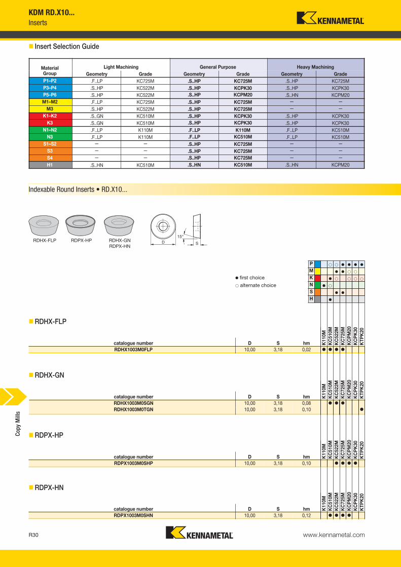
KDM RD.X10...Inserts
� Insert Selection Guide
MaterialGroup
Light Machining General Purpose Heavy MachiningGeometry Grade Geometry Grade Geometry Grade
P1–P2 .F..LP KC725M .S..HP KC725M .S..HP KC725MP3–P4 .S..HP KC522M .S..HP KCPK30 .S..HP KCPK30P5–P6 .S..HP KC522M .S..HP KCPM20 .S..HN KCPM20M1–M2 .F..LP KC725M .S..HP KC725M — —
M3 .S..HP KC522M .S..HP KC725M — —K1–K2 .S..GN KC510M .S..HP KCPK30 .S..HP KCPK30
K3 .S..GN KC510M .S..HP KCPK30 .S..HP KCPK30N1–N2 .F..LP K110M .F..LP K110M .F..LP KC510M
N3 .F..LP K110M .F..LP KC510M .F..LP KC510MS1–S2 — — .S..HP KC725M — —
S3 — — .S..HP KC725M — —S4 — — .S..HP KC725M — —H1 .S..HN KC510M .S..HN KC510M .S..HN KCPM20
P � � � � � �
M � � � �
K � � � � �
N � �
S � �
H �
catalogue number D S hm K11
0MK
C51
0MK
C52
2MK
C72
5MK
CP
M20
KC
PK
30K
TPK
20
RDHX1003M0FLP 10,00 3,18 0,02 � � � �
catalogue number D S hm K11
0MK
C51
0MK
C52
2MK
C72
5MK
CP
M20
KC
PK
30K
TPK
20
RDHX1003M0SGN 10,00 3,18 0,08 � � �
RDHX1003M0TGN 10,00 3,18 0,10 �
catalogue number D S hm K11
0MK
C51
0MK
C52
2MK
C72
5MK
CP
M20
KC
PK
30K
TPK
20
RDPX1003M0SHP 10,00 3,18 0,10 � � � �
catalogue number D S hm K11
0MK
C51
0MK
C52
2MK
C72
5MK
CP
M20
KC
PK
30K
TPK
20
RDPX1003M0SHN 10,00 3,18 0,12 � � � �
Indexable Round Inserts • RD.X10...
RDHX-FLP RDPX-HP RDHX-GNRDPX-HN
� first choice� alternate choice
� RDHX-FLP
� RDHX-GN
� RDPX-HP
� RDPX-HN
Copy
Mill
s
KM_Master12_R030_R031_METRIC_EN.qxp:Layout 1 3/7/12 9:56 AM Page R30

www.kennametal.com R31
Recommended Starting Speeds
MaterialGroup K110M KC510M KC522M KC725M
P
1 — — — — — — 395 345 325 315 275 2552 — — — — — — 330 290 240 260 230 1953 — — — — — — 305 255 215 240 205 1704 — — — 295 240 200 270 225 180 215 180 1455 — — — — — — 225 200 180 180 160 1456 — — — — — — 200 150 120 160 120 95
M1 — — — — — — 245 215 200 205 180 165
2 — — — — — — 225 190 160 185 160 130
3 — — — — — — 170 145 115 140 120 95
K1 155 145 135 350 315 285 275 250 220 — — —2 135 130 120 275 250 230 215 195 180 — — —3 120 105 95 235 205 190 180 160 145 — — —
N1–2 605 565 540 770 685 630 — — — — — —3 495 440 385 — — — — — — — — —
S
1 — — — — — — 50 45 35 45 35 302 — — — — — — 50 45 35 45 35 303 — — — — — — 60 50 35 55 45 304 — — — — — — 85 60 45 75 55 35
H 1 — — — 190 155 110 145 110 85 — — —
MaterialGroup KCPM20 KCPK30 KTPK20
P
1 660 580 535 545 475 440 440 360 3102 410 370 330 335 305 275 270 225 1903 370 330 305 305 275 250 245 205 1704 275 255 230 225 210 190 185 160 1305 330 300 275 310 275 255 255 205 1756 230 200 175 190 165 — 150 125 —
M1 270 240 205 250 220 190 285 235 2002 245 215 190 225 195 170 260 220 1853 195 175 150 175 160 140 195 160 —
K1 435 390 350 355 320 285 275 235 1952 345 310 280 280 255 230 220 180 1603 290 255 240 235 210 195 185 150 130
N1–2 — — — — — — — — —3 — — — — — — — — —
S
1 — — — — — — — — —2 — — — — — — — — —3 — — — — — — — — —4 — — — — — — — — —
H 1 170 140 115 — — — — — —
KDM RD.X10...
NOTE: FIRST choice starting speeds are in bold type.As the average chip thickness increases, the speed should be decreased.
� Recommended Starting Speeds [m/min]
Copy
Mill
s
KM_Master12_R030_R031_METRIC_EN.qxp:Layout 1 3/7/12 9:56 AM Page R31
www.kennametal.comR32
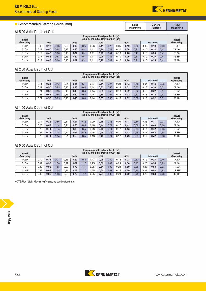
KDM RD.X10...Recommended Starting Feeds
InsertGeometry
Programmed Feed per Tooth (fz)as a % of Radial Depth of Cut (ae) Insert
Geometry10% 20% 30% 40% 50–100%.F..LP 0,08 0,17 0,33 0,06 0,13 0,25 0,06 0,11 0,22 0,05 0,10 0,20 0,05 0,10 0,20 .F..LP.S..GN 0,17 0,40 0,68 0,13 0,30 0,51 0,11 0,26 0,44 0,10 0,24 0,41 0,10 0,24 0,41 .S..GN.T..GN 0,17 0,43 0,68 0,13 0,32 0,51 0,11 0,28 0,44 0,10 0,26 0,41 0,10 0,25 0,41 .T..GN.S..HP 0,17 0,43 0,68 0,13 0,32 0,51 0,11 0,28 0,44 0,10 0,26 0,41 0,10 0,25 0,41 .S..HP.S..HN 0,17 0,43 0,68 0,13 0,32 0,51 0,11 0,28 0,44 0,10 0,26 0,41 0,10 0,25 0,41 .S..HN
InsertGeometry
Programmed Feed per Tooth (fz)as a % of Radial Depth of Cut (ae) Insert
Geometry10% 20% 30% 40% 50–100%.F..LP 0,11 0,21 0,42 0,08 0,16 0,31 0,07 0,14 0,27 0,06 0,13 0,26 0,06 0,13 0,25 .F..LP.S..GN 0,21 0,50 0,85 0,16 0,38 0,64 0,14 0,33 0,55 0,13 0,31 0,52 0,13 0,30 0,51 .S..GN.T..GN 0,21 0,53 0,85 0,16 0,40 0,64 0,14 0,35 0,55 0,13 0,32 0,52 0,13 0,32 0,51 .T..GN.S..HP 0,21 0,53 0,85 0,16 0,40 0,64 0,14 0,35 0,55 0,13 0,32 0,52 0,13 0,32 0,51 .S..HP.S..HN 0,21 0,53 0,85 0,16 0,40 0,64 0,14 0,35 0,55 0,13 0,32 0,52 0,13 0,32 0,51 .S..HN
InsertGeometry
Programmed Feed per Tooth (fz)as a % of Radial Depth of Cut (ae) Insert
Geometry10% 20% 30% 40% 50–100%.F..LP 0,14 0,28 0,56 0,11 0,21 0,42 0,09 0,18 0,36 0,09 0,17 0,34 0,08 0,17 0,33 .F..LP.S..GN 0,28 0,67 1,14 0,21 0,50 0,85 0,18 0,44 0,74 0,17 0,41 0,69 0,17 0,40 0,68 .S..GN.T..GN 0,28 0,71 1,14 0,21 0,53 0,85 0,18 0,46 0,74 0,17 0,43 0,69 0,17 0,42 0,68 .T..GN.S..HP 0,28 0,71 1,14 0,21 0,53 0,85 0,18 0,46 0,74 0,17 0,43 0,69 0,17 0,42 0,68 .S..HP.S..HN 0,28 0,71 1,14 0,21 0,53 0,85 0,18 0,46 0,74 0,17 0,43 0,69 0,17 0,42 0,68 .S..HN
InsertGeometry
Programmed Feed per Tooth (fz)as a % of Radial Depth of Cut (ae) Insert
Geometry10% 20% 30% 40% 50–100%.F..LP 0,19 0,38 0,77 0,15 0,29 0,58 0,13 0,25 0,50 0,12 0,23 0,47 0,12 0,23 0,46 .F..LP.S..GN 0,39 0,93 1,58 0,29 0,69 1,17 0,25 0,60 1,02 0,24 0,56 0,95 0,23 0,55 0,93 .S..GN.T..GN 0,39 0,98 1,58 0,29 0,73 1,17 0,25 0,64 1,02 0,24 0,59 0,95 0,23 0,58 0,93 .T..GN.S..HP 0,39 0,98 1,58 0,29 0,73 1,17 0,25 0,64 1,02 0,24 0,59 0,95 0,23 0,58 0,93 .S..HP.S..HN 0,39 0,98 1,58 0,29 0,73 1,17 0,25 0,64 1,02 0,24 0,59 0,95 0,23 0,58 0,93 .S..HN
NOTE: Use “Light Machining” values as starting feed rate.
Light Machining
General Purpose
Heavy Machining
� Recommended Starting Feeds [mm]
At 5,00 Axial Depth of Cut
At 2,00 Axial Depth of Cut
At 1,00 Axial Depth of Cut
At 0,50 Axial Depth of Cut
Copy
Mill
s
KM_Master12_R032_R033_METRIC_EN.qxp:Layout 1 3/7/12 9:50 AM Page R32

www.kennametal.com R33
order number catalogue number D1 max D1 D D2 DPM G3X L2 Ap1 max Zmax
ramp angle kg insert 11888421 24E02R035M12SRD12 24 12 21 21 12,5 M12 35 6,0 2 15.0° 0,08 RD___12T3_____1888422 35E03R043M16SRD12 35 23 29 33 17,0 M16 43 6,0 3 11.0° 0,21 RD___12T3_____
1888423 42E04R043M16SRD12 42 30 29 38 17,0 M16 43 6,0 4 11.0° 0,25 RD___12T3_____
D1 maxinsert screw Nm
Torx wrench
clampscrew
24 193.342 3,5 FT15 193.33835 193.342 3,5 FT15 193.338
42 193.342 3,5 FT15 193.338
KDM RD.X12...Indexable Screw-On End Mills • RD.X12...
• Engineered for maximum performance.
• High runout accuracy.
• Suitable for die and mould manufacturing.
� Screw-On End Mills • RD.X12 Inserts
� Spare Parts
Copy
Mill
s
KM_Master12_R032_R033_METRIC_EN.qxp:Layout 1 3/7/12 9:50 AM Page R33

www.kennametal.comR34
order number catalogue number D1 max D1 D D6 L Ap1 max Zmax
ramp angle kg insert 13680971 40A04RSMORD12 40 28 16 32 45 6,0 4 8.8° 0,34 RD.X12T3MO..3649673 50A05RSMORD12 50 38 22 42 50 6,0 5 6.1° 0,40 RD.X12T3MO..
1888182 52A05RSMORD12 52 40 22 42 50 6,0 5 4.5° 0,45 RD.X12T3MO..3681014 63A06RSMORD12 63 51 27 48 50 6,0 6 2.8° 0,71 RD.X12T3MO..
1888205 66A06RSMORD12 66 54 27 50 50 6,0 6 3.5° 0,75 RD.X12T3MO..1888200 80A07RSMORD12 80 68 27 50 50 6,0 7 2.5° 1,00 RD.X12T3MO..
D1 maxinsert screw Nm
Torx wrench
clampscrew
low-headcap screw
socket-headcap screw
40 193.342 3,5 FT15 193.338 — MS129450 193.342 3,5 FT15 193.338 129.025 —
52 193.342 3,5 FT15 193.338 129.025 —63 193.342 3,5 FT15 193.338 129.025 —
66 193.342 3,5 FT15 193.338 — MS203880 193.342 3,5 FT15 193.338 — —
KDM RD.X12...Indexable Shell Mills • RD.X12...
• Engineered for maximum performance.
• High runout accuracy.
• Suitable for die and mould manufacturing.
� Shell Mills • RD.X12 Inserts
� Spare Parts
Copy
Mill
s
KM_Master12_R034_R035_METRIC_EN.qxp:Layout 1 3/7/12 9:55 AM Page R34
www.kennametal.com R35
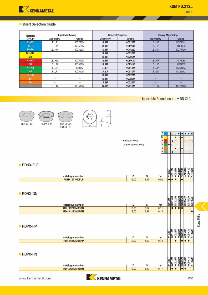
� Insert Selection Guide
MaterialGroup
Light Machining General Purpose Heavy MachiningGeometry Grade Geometry Grade Geometry Grade
P1–P2 .F..LP KC725M .S..HP KC725M .S..HP KC725MP3–P4 .S..HP KC522M .S..HP KCPK30 .S..HP KCPK30P5–P6 .S..HP KC522M .S..HP KCPM20 .S..HN KCPM20M1–M2 — — .S..HP KC725M — —
M3 — — .S..HP KC725M — —K1–K2 .S..HN KC510M .S..HP KCPK30 .S..HP KCPK30
K3 .S..HN KC510M .S..HP KCPK30 .S..HP KCPK30N1– N2 .F..LP K110M .F..LP KC510M .F..LP KC510M
N3 .F..LP KC510M .F..LP KC510M .F..GN KC510MS1–S2 — — .S..HP KC725M — —
S3 — — .S..HP KC725M — —S4 — — .S..HP KC725M — —H1 .S..HN KC510M .S..HN KC510M .S..HN KCPM20
P � � � � � � �
M � � � � �
K � � � � �
N � �
S � � �
H �
catalogue number D S hm K11
0MK
C51
0MK
C52
2MK
C52
5MK
C72
5MK
CP
M20
KC
PK
30K
TPK
20
RDHX12T3M0FLP 12,00 3,97 0,02 � � � �
catalogue number D S hm K11
0MK
C51
0MK
C52
2MK
C52
5MK
C72
5MK
CP
M20
KC
PK
30K
TPK
20
RDHX12T3M0SGN 12,00 3,97 0,11 � � � �
RDHX12T3M0TGN 12,00 3,97 0,13 �
catalogue number D S hm K11
0MK
C51
0MK
C52
2MK
C52
5MK
C72
5MK
CP
M20
KC
PK
30K
TPK
20
RDPX12T3M0SHP 12,00 3,97 0,13 � � � �
catalogue number D S hm K11
0MK
C51
0MK
C52
2MK
C52
5MK
C72
5MK
CP
M20
KC
PK
30K
TPK
20
RDPX12T3M0SHN 12,00 3,97 0,17 � � � �
Indexable Round Inserts • RD.X12...
RDHX-FLP RDPX-HP RDHX-GNRDPX-HN
� first choice� alternate choice
� RDHX-FLP
� RDHX-GN
� RDPX-HP
� RDPX-HN
KDM RD.X12...Inserts
Copy
Mill
s
KM_Master12_R034_R035_METRIC_EN.qxp:Layout 1 3/7/12 9:55 AM Page R35

www.kennametal.comR36
KDM RD.X12...Recommended Starting Speeds
MaterialGroup K110M KC510M KC522M KC525M
P
1 — — — — — — 395 345 325 260 240 215
2 — — — — — — 330 290 240 215 190 1803 — — — — — — 305 255 215 190 180 170
4 — — — 295 240 200 270 225 180 170 160 1455 — — — — — — 225 200 180 180 170 1606 — — — — — — 200 150 120 160 145 130
M
1 — — — — — — 245 215 200 180 170 160
2 — — — — — — 225 190 160 160 145 1303 — — — — — — 170 145 115 110 95 85
K
1 155 145 135 350 315 285 275 250 220 — — —
2 135 130 120 275 250 230 215 195 180 — — —
3 120 105 95 235 205 190 180 160 145 — — —
N1–2 605 565 540 770 685 630 — — — — — —3 495 440 385 — — — — — — — — —
S
1 — — — — — — 50 45 35 75 65 60
2 — — — — — — 50 45 35 75 65 603 — — — — — — 60 50 35 60 55 504 — — — — — — 85 60 45 75 60 50
H 1 — — — 190 155 110 145 110 85 — — —
NOTE: FIRST choice starting speeds are in bold type.As the average chip thickness increases, the speed should be decreased.
� Recommended Starting Speeds [m/min]
MaterialGroup KC725M KCPM20 KCPK30 KTPK20
P
1 315 275 255 660 580 535 545 475 440 440 360 310
2 260 230 195 410 370 330 335 305 275 270 225 190
3 240 205 170 370 330 305 305 275 250 245 205 170
4 215 180 145 275 255 230 225 210 190 185 160 130
5 180 160 145 330 300 275 310 275 255 255 205 1756 160 120 95 230 200 175 190 165 — 150 125 —
M
1 205 180 165 270 240 205 250 220 190 285 235 200
2 185 160 130 245 215 190 225 195 170 260 220 185
3 140 120 95 195 175 150 175 160 140 195 160 —
K
1 — — — 435 390 350 355 320 285 275 235 195
2 — — — 345 310 280 280 255 230 220 180 160
3 — — — 290 255 240 235 210 195 185 150 130
N1–2 — — — — — — — — — — — —3 — — — — — — — — — — — —
S
1 45 35 30 — — — — — — — — —
2 45 35 30 — — — — — — — — —
3 55 45 30 — — — — — — — — —4 75 55 35 — — — — — — — — —
H 1 — — — 170 140 115 — — — — — —
Copy
Mill
s
KM_Master12_R036_R037_METRIC_EN.qxp:Layout 1 3/7/12 9:55 AM Page R36

www.kennametal.com R37
KDM RD.X12...Recommended Starting Feeds
NOTE: Use “Light Machining” values as starting feed rate.
Light Machining
General Purpose
Heavy Machining
InsertGeometry
Programmed Feed per Tooth (fz)as a % of Radial Depth of Cut (ae) Insert
Geometry10% 20% 30% 40% 50–100%.F..LP 0,08 0,17 0,33 0,06 0,13 0,25 0,06 0,11 0,22 0,05 0,10 0,20 0,05 0,10 0,20 .F..LP.F..GN 0,08 0,17 0,33 0,06 0,13 0,25 0,06 0,11 0,22 0,05 0,10 0,20 0,05 0,10 0,20 .F..GN.T..GN 0,17 0,43 0,68 0,13 0,32 0,51 0,11 0,28 0,44 0,10 0,26 0,41 0,10 0,25 0,41 .T..GN.S..GN 0,17 0,43 0,68 0,13 0,32 0,51 0,11 0,28 0,44 0,10 0,26 0,41 0,10 0,25 0,41 .S..GN.S..HP 0,17 0,43 0,68 0,13 0,32 0,51 0,11 0,28 0,44 0,10 0,26 0,41 0,10 0,25 0,41 .S..HP.S..HN 0,17 0,43 0,68 0,13 0,32 0,51 0,11 0,28 0,44 0,10 0,26 0,41 0,10 0,25 0,41 .S..HN
InsertGeometry
Programmed Feed per Tooth (fz)as a % of Radial Depth of Cut (ae) Insert
Geometry10% 20% 30% 40% 50–100%.F..LP 0,10 0,19 0,39 0,07 0,14 0,29 0,06 0,13 0,25 0,06 0,12 0,24 0,06 0,12 0,23 .F..LP.F..GN 0,10 0,19 0,39 0,07 0,14 0,29 0,06 0,13 0,25 0,06 0,12 0,24 0,06 0,12 0,23 .F..GN.T..GN 0,20 0,49 0,79 0,15 0,37 0,59 0,13 0,32 0,51 0,12 0,30 0,48 0,12 0,29 0,47 .T..GN.S..GN 0,20 0,49 0,79 0,15 0,37 0,59 0,13 0,32 0,51 0,12 0,30 0,48 0,12 0,29 0,47 .S..GN.S..HP 0,20 0,49 0,79 0,15 0,37 0,59 0,13 0,32 0,51 0,12 0,30 0,48 0,12 0,29 0,47 .S..HP.S..HN 0,20 0,49 0,79 0,15 0,37 0,59 0,13 0,32 0,51 0,12 0,30 0,48 0,12 0,29 0,47 .S..HN
InsertGeometry
Programmed Feed per Tooth (fz)as a % of Radial Depth of Cut (ae) Insert
Geometry10% 20% 30% 40% 50–100%.F..LP 0,13 0,25 0,51 0,10 0,19 0,38 0,08 0,17 0,33 0,08 0,15 0,31 0,08 0,15 0,30 .F..LP.F..GN 0,13 0,25 0,51 0,10 0,19 0,38 0,08 0,17 0,33 0,08 0,15 0,31 0,08 0,15 0,30 .F..GN.T..GN 0,26 0,64 1,04 0,19 0,48 0,77 0,17 0,42 0,67 0,16 0,39 0,63 0,15 0,38 0,61 .T..GN.S..GN 0,26 0,64 1,04 0,19 0,48 0,77 0,17 0,42 0,67 0,16 0,39 0,63 0,15 0,38 0,61 .S..GN.S..HP 0,26 0,64 1,04 0,19 0,48 0,77 0,17 0,42 0,67 0,16 0,39 0,63 0,15 0,38 0,61 .S..HP.S..HN 0,26 0,64 1,04 0,19 0,48 0,77 0,17 0,42 0,67 0,16 0,39 0,63 0,15 0,38 0,61 .S..HN
InsertGeometry
Programmed Feed per Tooth (fz)as a % of Radial Depth of Cut (ae) Insert
Geometry10% 20% 30% 40% 50–100%.F..LP 0,18 0,35 0,69 0,13 0,26 0,52 0,11 0,23 0,45 0,11 0,21 0,42 0,10 0,21 0,41 .F..LP.F..GN 0,18 0,35 0,69 0,13 0,26 0,52 0,11 0,23 0,45 0,11 0,21 0,42 0,10 0,21 0,41 .F..GN.T..GN 0,35 0,88 1,42 0,26 0,66 1,05 0,23 0,57 0,92 0,21 0,54 0,86 0,21 0,52 0,84 .T..GN.S..GN 0,35 0,88 1,42 0,26 0,66 1,05 0,23 0,57 0,92 0,21 0,54 0,86 0,21 0,52 0,84 .S..GN.S..HP 0,35 0,88 1,42 0,26 0,66 1,05 0,23 0,57 0,92 0,21 0,54 0,86 0,21 0,52 0,84 .S..HP.S..HN 0,35 0,88 1,42 0,26 0,66 1,05 0,23 0,57 0,92 0,21 0,54 0,86 0,21 0,52 0,84 .S..HN
� Recommended Starting Feeds [mm]
At 6,00 Axial Depth of Cut (ap)
At 3,00 Axial Depth of Cut (ap)
At 1,50 Axial Depth of Cut (ap)
At 0,75 Axial Depth of Cut (ap)
Copy
Mill
s
KM_Master12_R036_R037_METRIC_EN.qxp:Layout 1 3/7/12 9:55 AM Page R37

www.kennametal.comR38
D1 maxinsert screw Nm
Torx wrench
32 193.343 6,0 FT20
KDM RD.X16...
� Screw-On End Mills • RD.X16 Inserts
� Spare Parts
order number catalogue number D1 max D1 D D6 L Ap1 max Zmax
ramp angle kg insert 13681013 50A04RSMORD16 50 34 22 42 50 8,0 4 8.5° 0,32 RD_X1604M0__1888196 52A04RSMORD16 52 36 22 42 50 8,0 4 8.2° 0,32 RD_X1604M0__
3681015 63A05RSMORD16 63 47 22 48 50 8,0 5 5.5° 0,55 RD_X1604M0__1888209 66A05RSMORD16 66 50 27 50 50 8,0 5 4.0° 0,55 RD_X1604M0__
1888204 80A06RSMORD16 80 64 27 50 50 8,0 6 3.0° 0,87 RD_X1604M0__1888197 100B07RSMORD16 100 84 32 60 55 8,0 7 2.0° 1,37 RD_X1604MO__
• Engineered for maximum performance.
• High runout accuracy.
• Suitable for die and mould manufacturing.
� Shell Mills • RD.X16 Inserts
� Spare Parts
Indexable Screw-On End Mills • Indexable Shell Mills • RD.X16...
D1 maxinsert screw Nm
Torx wrench
clampscrew
50 193.343 6,0 FT20 193.38352 193.343 6,0 FT20 193.383
63 193.343 6,0 FT20 193.38366 193.343 6,0 FT20 193.383
80 193.343 6,0 FT20 193.383100 193.343 6,0 FT20 193.383
Copy
Mill
s
order number catalogue number D1 max D1 D D2 DPM G3X L2 Ap1 max Zmax
ramp angle kg insert 11888424 32E02R043M16SRD16 32 16 29 27 17,0 M16 43 8,0 2 15.0° 0,20 RD___1604_____
• Engineered for maximum performance.
• High runout accuracy.
• Suitable for die and mould manufacturing.
KM_Master12_R038_R039_METRIC_EN.qxp:Layout 1 3/28/12 11:27 AM Page R38

www.kennametal.com R39
KDM RD.X16...Inserts
� Insert Selection Guide
MaterialGroup
Light Machining General Purpose Heavy MachiningGeometry Grade Geometry Grade Geometry Grade
P1–P2 .F..LP KC725M .S..GN KC725M .S..HP KC725MP3–P4 .S..HP KC522M .S..HP KCPK30 .S..HN KC725MP5–P6 .S..HP KC522M .S..HP KCPM20 .S..HN KCPM20M1–M2 — — .S..HP KC725M — —
M3 — — .S..HP KC725M — —K1–K2 .S..HN KC510M .S..HP KCPK30 .S..HP KCPK30
K3 .S..HN KC510M .S..HP KCPK30 .S..HP KCPK30N1–N2 .F..LP KC510M .F..LP KC510M .F..LP KC510M
N3 .F..LP KC510M .F..LP KC510M .F..LP KC510MS1–S2 — — .S..HP KC725M — —
S3 — — .S..HP KC725M — —S4 — — .S..HP KC725M — —H1 .S..GN KC510M .S..HN KC510M .S..HN KCPM20
P � � � � �
M � � � �
K � � � �
N �
S � �
H �
catalogue number D S hm KC
510M
KC
522M
KC
725M
KC
PM
20K
CP
K30
RDHX1604M0FLP 16,00 4,76 0,02 � � �
catalogue number D S hm KC
510M
KC
522M
KC
725M
KC
PM
20K
CP
K30
RDHX1604M0SGN 16,00 4,76 0,21 � � �
catalogue number D S hm KC
510M
KC
522M
KC
725M
KC
PM
20K
CP
K30
RDPX1604M0SHP 16,00 4,76 0,14 � � � �
catalogue number D S hm KC
510M
KC
522M
KC
725M
KC
PM
20K
CP
K30
RDPX1604M0SHN 16,00 4,76 0,21 � � � �
Indexable Round Inserts • KDM RD.X16...
RDHX-FLP RDPX-HP RDHX-GNRDPX-HN
� first choice� alternate choice
� RDHX-FLP
� RDHX-GN
� RDPX-HP
� RDPX-HN
Copy
Mill
s
KM_Master12_R038_R039_METRIC_EN.qxp:Layout 1 3/28/12 11:27 AM Page R39

www.kennametal.comR40
KDM RD.X16...Recommended Starting Speeds and Feeds
MaterialGroup KC510M KC522M KC725M KCPM20 KCPK30
P
1 — — — 395 345 325 315 275 255 660 580 535 545 475 4402 — — — 330 290 240 260 230 195 410 370 330 335 305 2753 — — — 305 255 215 240 205 170 370 330 305 305 275 2504 295 240 200 270 225 180 215 180 145 275 255 230 225 210 1905 — — — 225 200 180 180 160 145 330 300 275 310 275 2556 — — — 200 150 120 160 120 95 230 200 175 190 165 —
M1 — — — 245 215 200 205 180 165 270 240 205 250 220 1902 — — — 225 190 160 185 160 130 245 215 190 225 195 1703 — — — 170 145 115 140 120 95 195 175 150 175 160 140
K1 350 315 285 275 250 220 — — — 435 390 350 355 320 2852 275 250 230 215 195 180 — — — 345 310 280 280 255 2303 235 205 190 180 160 145 — — — 290 255 240 235 210 195
N1–2 770 685 630 — — — — — — — — — — — —3 — — — — — — — — — — — — — — —
S
1 — — — 50 45 35 45 35 30 — — — — — —2 — — — 50 45 35 45 35 30 — — — — — —3 — — — 60 50 35 55 45 30 — — — — — —4 — — — 85 60 45 75 55 35 — — — — — —
H 1 190 155 110 145 110 85 — — — 170 140 115 — — —
NOTE: FIRST choice starting speeds are in bold type.As the average chip thickness increases, the speed should be decreased.
InsertGeometry
Programmed Feed per Tooth (fz)as a % of Radial Depth of Cut (ae) Insert
Geometry10% 20% 30% 40% 50–100%.F..LP 0,08 0,17 0,33 0,06 0,13 0,25 0,06 0,11 0,22 0,05 0,10 0,20 0,05 0,10 0,20 .F..LP.S..GN 0,17 0,43 0,68 0,13 0,32 0,51 0,11 0,28 0,44 0,10 0,26 0,41 0,10 0,25 0,41 .S..GN.S..HP 0,17 0,43 0,68 0,13 0,32 0,51 0,11 0,28 0,44 0,10 0,26 0,41 0,10 0,25 0,41 .S..HP.S..HN 0,17 0,43 0,68 0,13 0,32 0,51 0,11 0,28 0,44 0,10 0,26 0,41 0,10 0,25 0,41 .S..HN
InsertGeometry
Programmed Feed per Tooth (fz)as a % of Radial Depth of Cut (ae) Insert
Geometry10% 20% 30% 40% 50–100%.F..LP 0,10 0,19 0,39 0,07 0,14 0,29 0,06 0,13 0,25 0,06 0,12 0,24 0,06 0,12 0,23 .F..LP.S..GN 0,20 0,49 0,79 0,15 0,37 0,59 0,13 0,32 0,51 0,12 0,30 0,48 0,12 0,29 0,47 .S..GN.S..HP 0,20 0,49 0,79 0,15 0,37 0,59 0,13 0,32 0,51 0,12 0,30 0,48 0,12 0,29 0,47 .S..HP.S..HN 0,20 0,49 0,79 0,15 0,37 0,59 0,13 0,32 0,51 0,12 0,30 0,48 0,12 0,29 0,47 .S..HN
InsertGeometry
Programmed Feed per Tooth (fz)as a % of Radial Depth of Cut (ae) Insert
Geometry10% 20% 30% 40% 50–100%.F..LP 0,13 0,25 0,51 0,10 0,19 0,38 0,08 0,17 0,33 0,08 0,15 0,31 0,08 0,15 0,30 .F..LP.S..GN 0,26 0,64 1,04 0,19 0,48 0,77 0,17 0,42 0,67 0,16 0,39 0,63 0,15 0,38 0,61 .S..GN.S..HP 0,26 0,64 1,04 0,19 0,48 0,77 0,17 0,42 0,67 0,16 0,39 0,63 0,15 0,38 0,61 .S..HP.S..HN 0,26 0,64 1,04 0,19 0,48 0,77 0,17 0,42 0,67 0,16 0,39 0,63 0,15 0,38 0,61 .S..HN
InsertGeometry
Programmed Feed per Tooth (fz)as a % of Radial Depth of Cut (ae) Insert
Geometry10% 20% 30% 40% 50–100%.F..LP 0,18 0,35 0,69 0,13 0,26 0,52 0,11 0,23 0,45 0,11 0,21 0,42 0,10 0,21 0,41 .F..LP.S..GN 0,35 0,88 1,42 0,26 0,66 1,05 0,23 0,57 0,92 0,21 0,54 0,86 0,21 0,52 0,84 .S..GN.S..HP 0,35 0,88 1,42 0,26 0,66 1,05 0,23 0,57 0,92 0,21 0,54 0,86 0,21 0,52 0,84 .S..HP.S..HN 0,35 0,88 1,42 0,26 0,66 1,05 0,23 0,57 0,92 0,21 0,54 0,86 0,21 0,52 0,84 .S..HN
NOTE: Use “Light Machining” values as starting feed rate.
� Recommended Starting Speeds [m/min]
� Recommended Starting Feeds [mm] Light Machining
General Purpose
Heavy Machining
At 8,00 Axial Depth of Cut (ap)
At 4,00 Axial Depth of Cut (ap)
At 2,00 Axial Depth of Cut (ap)
At 1,00 Axial Depth of Cut (ap)
Copy
Mill
s
KM_Master12_R040_R041_METRIC_EN.qxp:Layout 1 3/7/12 9:54 AM Page R40

www.kennametal.com R41www.kennametal.com
At Kennametal, innovation follows vision. Our revolutionary products and services are inspired by asking “what if?” The solutions that follow — like our Beyond BLAST through-coolant inserts — deliver remarkable results in the world’s most demanding machining environments.
A cutting-edge insert that delivers coolant precisely at the cutting edge. Now that’s Different Thinking. That’s Kennametal.
To learn more about your productivity gains using Beyond BLAST technology, visit www.kennametal.com.
More than just the right tool • the ultimate solution.
That’s Beyond BLAST.™
That’s Different Thinking.
Milling• Beyond BLAST technology uses low-pressure conditions to offer many
of the high-pressure performance benefits. • Delivers superior performance on titanium, using either high- or low-pressure
coolant systems.• Effective thermal management results in reduced cutting temperatures,
improved lubricity, superior chip control, and longer tool life.• Beyond BLAST for milling increases tool life by up to 100% compared
with conventional coolant delivery systems.
KM_Master12_R040_R041_METRIC_EN.qxp:Layout 1 3/7/12 9:54 AM Page R41

Features and Benefits
KSRM™ • Multipurpose Milling Cutters
Primary ApplicationSpecially developed for machining titanium and stainless steel. KSRM platform enables you to pocket, profile, ramp, and plunge with up to 1mm (.039") fz with consistent performance, providing outstanding metal removal rates with the lowest cutting forces in roughing applications.
www.kennametal.comR42
Up to eight indexablepositions for fast and
accurate insert changes.
High clearance on the cutters fora superior plunging, ramping,
and chip load capacities.
Anti-rotation screw provides excellent stabilitywith higher feed rates and cutting forces.
High positive rake angle with stronger cutting edge inserts for lower cutting forces, specially developed for machining titanium.
Screw-On, end mill, and shell millcutters with internal coolant.
KM_Master12_R042_R043_METRIC_EN.qxp:Layout 1 3/9/12 10:28 AM Page R42

www.kennametal.com R43
order number catalogue number D1 max D1 D DPM G3X L2 Ap1 max Zmax
ramp angle max RPM kg insert 14043046 32E03R045M16RP12 32 20 29 17,0 M16 45 6,0 3 6° 43400 0,18 RP.T1204M0…4043047 40E04R045M16RP12 40 28 29 17,0 M16 45 6,0 4 9° 38800 0,21 RP.T1204M0…
D1 maxinsert screw Nm
anti-rotationscrew
Torx Plus driver
32 MS2077 2,3 MS-2225 DT15IP40 MS2077 2,3 MS-2225 DT15IP
KSRM™ RP.T1204
• Engineered for titanium and stainless steel machining.
• Anti-rotation components feature eight indexable positions.
• Pocketing, ramping, plunging, and helical interpolation capabilities.
� Screw-On End Mills
� Spare Parts
order number catalogue number D1 max D1 D L L2 Ap1 max Zmax
ramp angle kg max RPM insert 14043048 32A03R040B32RP12 32 20 32 101 40 6,0 3 6.0° 0,51 43400 RP.T1204M0…
� Weldon End Mills
� Spare Parts
Screw-On End Mills • Weldon® End Mills • Metric
Copy
Mill
s
D1 maxinsert screw Nm
anti-rotationscrew
Torx Plus driver
32 MS2077 2,3 MS-2225 DT15IP
KM_Master12_R042_R043_METRIC_EN.qxp:Layout 1 3/9/12 10:28 AM Page R43

www.kennametal.comR44
order number catalogue number D1 max D1 D L L2 Ap1 max Zmax
ramp angle kg max RPM insert 14043049 32A03R040A32RP12L190 32 20 32 190 40 6,0 3 6.0° 1,05 43400 RP_T1204M0__4177164 35E03R050A32RP12L200 35 23 32 200 50 6,0 3 5.5° 1,11 41400 RP_T1204M0__
4177052 35E04R050A32RP12L200 35 23 32 200 50 6,0 4 7.0° 1,11 41400 RP_T1204M0__
D1 maxinsert screw Nm
anti-rotationscrew
Torx Plus driver
32 MS2077 2,3 MS-2225 DT15IP35 MS2077 2,3 MS-2225 DT15IP
KSRM™ RP.T1204Cylindrical End Mills • Metric
• Engineered for titanium and stainless steel machining.
• Anti-rotation components feature eight indexable positions.
• Pocketing, ramping, plunging, and helical interpolation capabilities.
� Cylindrical End Mills
� Spare Parts
Copy
Mill
s
KM_Master12_R044_R045_METRIC_EN.qxp:Layout 1 3/7/12 9:54 AM Page R44

www.kennametal.com R45
KSRM™ RP.T1204Face Mills • Metric
• Engineered for titanium and stainless steel machining.
• Anti-rotation components feature eight indexable positions.
• Pocketing, ramping, plunging, and helical interpolation capabilities.
� Face Mills
� Spare Parts
order number catalogue number D1 max D1 D D6 L Ap1 max Zmax
ramp angle kg max RPM insert 14043050 40A04RS90RP12 40 28 16 38 40 6,0 4 9.0° 0,21 38800 RP.T1204M0…4177163 42A04RS90RP12 42 30 16 38 40 6,0 4 10.0° 0,22 37800 RP.T1204M0..
4043051 50A04RS90RP12 50 38 22 42 40 6,0 4 10.8° 0,26 34700 RP.T1204M0...4043052 50A05RS90RP12 50 38 22 42 40 6,0 5 7.9° 0,26 34700 RP.T1204M0...
3891914 52A05RS90RP12 52 40 22 49 50 6,0 5 10.2° 0,50 34000 RP.T1204M0…4043063 63A05RS90RP12 63 51 22 49 50 6,0 5 7.7° 0,56 30900 RP.T1204M0…
4025498 63A07RS90RP12 63 51 22 49 50 6,0 7 2.6° 0,56 30900 RP.T1204M0…4005063 66A06RS90RP12 66 54 27 60 50 6,0 6 6.6° 0,74 30200 RP.T1204M0…
4043064 80A06RS90RP12 80 68 27 60 50 6,0 6 5.1° 0,95 27300 RP.T1204M0…4024763 80A08RS90RP12 80 68 27 60 50 6,0 8 4.1° 0,96 27300 RP.T1204M0…
4043065 100B07RS90RP12 100 88 32 78 50 6,0 7 4.0° 1,39 24000 RP.T1204M0…4027389 100B09RS90RP12 100 88 32 78 50 6,0 9 3.1° 1,39 24000 RP.T1204M0…
D1 maxinsert screw Nm
anti-rotationscrew
low-headcap screw
socket-headcap screw
socket-head cap screwwith coolant groove *
coolant lock screw assembly
T-handlehex wrench
Torx Plus driver
40 MS2077 2,3 MS-2225 — MS1294 MS1294CG — — DT15IP42 MS2077 2,3 MS-2225 — MS1294 MS1294CG — — DT15IP
50 MS2077 2,3 MS-2225 MS1336 — MS2072CG — — DT15IP52 MS2077 2,3 MS-2225 — MS1242 MS1242CG — — DT15IP
63 MS2077 2,3 MS-2225 — MS1242 MS1242CG — — DT15IP66 MS2077 2,3 MS-2225 — MS2038 MS2038CG — — DT15IP
80 MS2077 2,3 MS-2225 — MS2038 MS2038CG — — DT15IP100 MS2077 2,3 MS-2225 — — — MS2195C THW2M DT15IP
Copy
Mill
s
* Socket head cap screw with coolant groove sold separately as a spare part.
KM_Master12_R044_R045_METRIC_EN.qxp:Layout 1 3/7/12 9:54 AM Page R45

www.kennametal.comR46
� Insert Selection Guide
RPET-LERPET-GE
RPPT-GP
• SGE and ELE are the first choice for titanium machining.
• SGE geometry is the first choice for medium and heavy applications.
• ELE is the first choice for lower cutting forces to avoid built-up edge.
� first choice� alternate choice
� RPET-LE
� RPET-GE
� RPPT-GP
MaterialGroup
Light Machining General Purpose Heavy MachiningGeometry Grade Geometry Grade Geometry Grade
P1–P2 .E..LE KC725M .S..GE KC725M .S..GP KC725MP3–P4 .E..LE KCPK30 .S..GE KCPK30 .S..GP KCPK30P5–P6 .S..GE KCPK30 .S..GP KCPK30 .S..GP KCPM20M1–M2 .E..LE KC725M .E..LE KC725M .S..GE KC725M
M3 .E..LE KCPK30 .E..LE KCPK30 .S..GE KCPK30K1–K2 — — .S..GP KCPK30 — —
K3 — — .S..GP KCPK30 — —N1–N2 .E..LEJ KC422M .E..LEJ KC422M .E..LEJ KC422M
N3 .E..LEJ KC422M .E..LEJ KC422M .E..LEJ KC422MS1–S2 .E..LE KC725M .S..GE KC725M .S..GP KC725M
S3 .E..LE KC725M .S..GE KC725M .S..GP KC725MS4 .E..LE KC725M .E..LE KC725M .S..GE KC725MH1 — — — — — —
catalogue number D S hmcutting edges K
C42
2MK
C52
2MK
C72
5MK
CP
M20
KC
PK
30
RPET1204M0ELEJ 12,00 4,76 0,03 8 � � �
RPET1204M0ELE 12,00 4,76 0,05 8 � � �
catalogue number D S hmcutting edges K
C42
2MK
C52
2MK
C72
5MK
CP
M20
KC
PK
30
RPET1204M0SGE 12,00 4,76 0,10 8 � � �
RPET1204M0SGEJ 12,00 4,76 0,11 8 � �
catalogue number D S hmcutting edges K
C42
2MK
C52
2MK
C72
5MK
CP
M20
KC
PK
30
RPPT1204M0SGP 12,00 4,76 0,13 8 � � �
Indexable Round Inserts • KSRM
P � � � �
M � � � �
K � � �
N �
S � �
H
KSRM™ RP.T1204Inserts
Copy
Mill
s
KM_Master12_R046_R047_METRIC_EN.qxp:Layout 1 3/7/12 9:54 AM Page R46

www.kennametal.com R47
MaterialGroup KC422M KC522M KC725M KCPM20 KCPK30
P
1 — — — 395 345 325 315 275 255 660 580 535 545 475 4402 — — — 330 290 240 260 230 195 410 370 330 335 305 2753 — — — 305 255 215 240 205 170 370 330 305 305 275 2504 — — — 270 225 180 215 180 145 275 255 230 225 210 1905 — — — 225 200 180 180 160 145 330 300 275 310 275 2556 — — — 200 150 120 160 120 95 230 200 175 190 165 —
M1 — — — 245 215 200 205 180 165 270 240 205 250 220 1902 — — — 225 190 160 185 160 130 245 215 190 225 195 1703 — — — 170 145 115 140 120 95 195 175 150 175 160 140
K1 — — — 275 250 220 — — — 435 390 350 355 320 2852 — — — 215 195 180 — — — 345 310 280 280 255 2303 — — — 180 160 145 — — — 290 255 240 235 210 195
N1–2 1285 1135 1050 — — — — — — — — — — — —3 1135 1050 915 — — — — — — — — — — — —
S
1 — — — 50 45 35 45 35 30 — — — — — —2 — — — 50 45 35 45 35 30 — — — — — —3 — — — 60 50 35 55 45 30 — — — — — —4 — — — 85 60 45 75 55 35 — — — — — —
H 1 — — — — — — — — — — — — — — —
KSRM™ RP.T1204
NOTE: FIRST choice starting speeds are in bold type.As the average chip thickness increases, the speed should be decreased.
InsertGeometry
Programmed Feed per Tooth (fz)as a % of Radial Depth of Cut (ae) Insert
Geometry10% 20% 30% 40% 50–100%.E..LEJ 0,08 0,13 0,20 0,06 0,09 0,15 0,06 0,08 0,13 0,05 0,08 0,12 0,05 0,08 0,12 .E..LEJ.E..LE 0,12 0,21 0,34 0,09 0,16 0,26 0,08 0,14 0,22 0,07 0,13 0,21 0,07 0,13 0,20 .E..LE.S..GE 0,17 0,43 0,68 0,13 0,32 0,51 0,11 0,28 0,44 0,10 0,26 0,41 0,10 0,25 0,41 .S..GE.S..GP 0,17 0,43 0,68 0,13 0,32 0,51 0,11 0,28 0,44 0,10 0,26 0,41 0,10 0,25 0,41 .S..GP
InsertGeometry
Programmed Feed per Tooth (fz)as a % of Radial Depth of Cut (ae) Insert
Geometry10% 20% 30% 40% 50–100%.E..LEJ 0,10 0,14 0,23 0,07 0,11 0,17 0,06 0,09 0,15 0,06 0,09 0,14 0,06 0,09 0,14 .E..LEJ.E..LE 0,14 0,25 0,39 0,10 0,18 0,29 0,09 0,16 0,26 0,09 0,15 0,24 0,08 0,15 0,24 .E..LE.S..GE 0,20 0,49 0,79 0,15 0,37 0,59 0,13 0,32 0,51 0,12 0,30 0,48 0,12 0,29 0,47 .S..GE.S..GP 0,20 0,49 0,79 0,15 0,37 0,59 0,13 0,32 0,51 0,12 0,30 0,48 0,12 0,29 0,47 .S..GP
InsertGeometry
Programmed Feed per Tooth (fz)as a % of Radial Depth of Cut (ae) Insert
Geometry10% 20% 30% 40% 50–100%.E..LEJ 0,13 0,19 0,30 0,10 0,14 0,23 0,08 0,12 0,20 0,08 0,12 0,19 0,08 0,11 0,18 .E..LEJ.E..LE 0,18 0,32 0,52 0,14 0,24 0,39 0,12 0,21 0,34 0,11 0,20 0,31 0,11 0,19 0,31 .E..LE.S..GE 0,26 0,64 1,04 0,19 0,48 0,77 0,17 0,42 0,67 0,16 0,39 0,63 0,15 0,38 0,61 .S..GE.S..GP 0,26 0,64 1,04 0,19 0,48 0,77 0,17 0,42 0,67 0,16 0,39 0,63 0,15 0,38 0,61 .S..GP
InsertGeometry
Programmed Feed per Tooth (fz)as a % of Radial Depth of Cut (ae) Insert
Geometry10% 20% 30% 40% 50–100%.E..LEJ 0,18 0,26 0,41 0,13 0,19 0,31 0,11 0,17 0,27 0,11 0,16 0,25 0,10 0,15 0,25 .E..LEJ.E..LE 0,25 0,44 0,71 0,19 0,33 0,53 0,16 0,29 0,46 0,15 0,27 0,43 0,15 0,26 0,42 .E..LE.S..GE 0,35 0,88 1,42 0,26 0,66 1,05 0,23 0,57 0,92 0,21 0,54 0,86 0,21 0,52 0,84 .S..GE.S..GP 0,35 0,88 1,42 0,26 0,66 1,05 0,23 0,57 0,92 0,21 0,54 0,86 0,21 0,52 0,84 .S..GP
Light Machining
General Purpose
Heavy Machining
NOTE: Use “Light Machining” values as starting feed rate.
� Recommended Starting Speeds [m/min]
� Recommended Starting Feeds [mm]
Recommended Starting Speeds and Feeds
At 6,00 Axial Depth of Cut (ap)
At 3,00 Axial Depth of Cut (ap)
At 1,50 Axial Depth of Cut (ap)
At 0,75 Axial Depth of Cut (ap)
Copy
Mill
s
KM_Master12_R046_R047_METRIC_EN.qxp:Layout 1 3/7/12 9:54 AM Page R47

www.kennametal.comR48
catalogue numbermax
ramp anglemax
plunging depthmin hole
diameter (DH min)max flat-bottom
hole diameter (DH1 max)max hole diameter
(flat bottom)32E03R045M16RP12 6.0° 1,65 43,95 52 6440E04R045M16RP12 9.0° 3,50 57,24 68 80
32A03R040B32RP12 6.0° 1,65 43,95 52 6432A03R040A32RP12L190 6.0° 1,65 43,95 52 64
40A04RS90RP12 9.0° 3,50 57,24 68 8050A04RS90RP12 10.8° 6,00 76,04 88 100
50A05RS90RP12 7.9° 4,40 76,50 88 10052A05RS90RP12 10.2° 6,00 80,05 92 104
63A05RS90RP12 7.7° 6,00 102,02 114 12663A07RS90RP12 2.6° 2,10 105,08 114 126
66A06RS90RP12 6.6° 5,50 108,14 120 13280A06RS90RP12 5.1° 5,50 136,04 148 160
80A08RS90RP12 4.1° 4,40 136,58 148 160100B07RS90RP12 4.0° 5,70 176,04 188 200
100B09RS90RP12 3.1° 4,40 176,55 188 200
KSRM™ RP.T1204
ramp angle
shoulder cut
rampinghelical
interpolation
Ø DH/DH1DH min = Minimum blind hole diameter with helical interpolation
DH1 max = Maximum flat-bottom hole diameter
Application Data
� Maximum Linear Ramping and Helical Interpolation from Solid
Copy
Mill
s
KM_Master12_R048_R049_METRIC_EN.qxp:Layout 1 3/28/12 11:30 AM Page R48
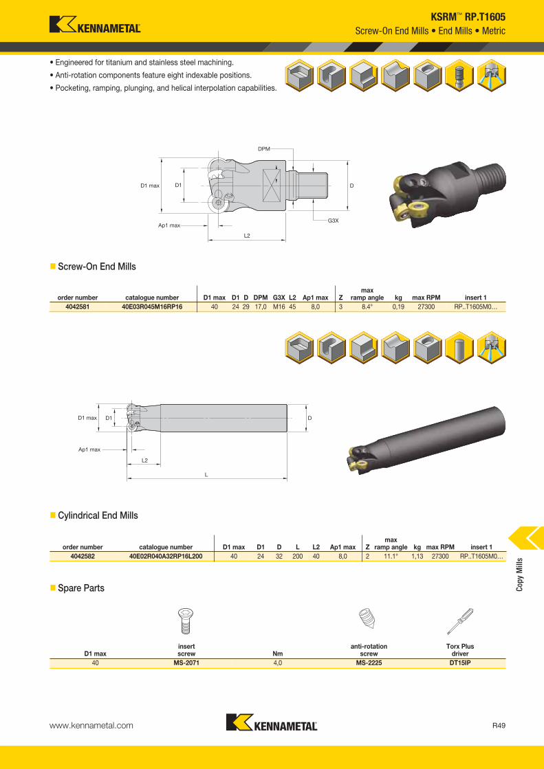
www.kennametal.com R49
KSRM™ RP.T1605
• Engineered for titanium and stainless steel machining.
• Anti-rotation components feature eight indexable positions.
• Pocketing, ramping, plunging, and helical interpolation capabilities.
� Screw-On End Mills
order number catalogue number D1 max D1 D L L2 Ap1 max Zmax
ramp angle kg max RPM insert 14042582 40E02R040A32RP16L200 40 24 32 200 40 8,0 2 11.1° 1,13 27300 RP..T1605M0…
D1 maxinsert screw Nm
anti-rotationscrew
Torx Plus driver
40 MS-2071 4,0 MS-2225 DT15IP
� Cylindrical End Mills
� Spare Parts
Screw-On End Mills • End Mills • Metric
Copy
Mill
s
order number catalogue number D1 max D1 D DPM G3X L2 Ap1 max Zmax
ramp angle kg max RPM insert 14042581 40E03R045M16RP16 40 24 29 17,0 M16 45 8,0 3 8.4° 0,19 27300 RP..T1605M0…
KM_Master12_R048_R049_METRIC_EN.qxp:Layout 1 3/28/12 11:30 AM Page R49

www.kennametal.comR50
order number catalogue number D1 max D1 D D6 L Ap1 max Zmax
ramp angle kg max RPM insert 14042693 52A04RS90RP16 52 36 22 49 50 8,0 4 11° 0,42 23900 RP..T1605M0…4042694 63A04RS90RP16 63 47 22 49 50 8,0 4 12° 0,50 21700 RP..T1605M0…
4042695 63A06RS90RP16 63 47 22 49 50 8,0 6 4° 0,51 21700 RP..T1605M0…4042696 80A05RS90RP16 80 64 27 60 50 8,0 5 8° 0,87 19200 RP..T1605M0…
4042697 80A07RS90RP16 80 64 27 60 50 8,0 7 5° 0,90 19200 RP..T1605M0…4042698 100B06RS90RP16 100 84 32 78 50 8,0 6 6° 1,29 16700 RP..T1605M0…
4042699 100B08RS90RP16 100 84 32 78 50 8,0 8 5° 1,29 16700 RP..T1605M0…4042700 125B09RS90RP16 125 109 40 90 63 8,0 9 4° 2,48 14700 RP..T1605M0…
D1 maxinsert screw Nm
anti-rotationscrew
socket-headcap screw
socket-head cap screwwith coolant groove *
coolant lock screw assembly
T-handlehex wrench
Torx Plus driver
52 MS-2071 4,0 MS-2225 MS1242 MS1242CG — — DT15IP63 MS-2071 4,0 MS-2225 MS1242 MS1242CG — — DT15IP
80 MS-2071 4,0 MS-2225 MS2038 MS2038CG — — DT15IP100 MS-2071 4,0 MS-2225 — — MS2195C THW2M DT15IP
125 MS-2071 4,0 MS-2225 — — MS2187C THW2M DT15IP
KSRM™ RP.T1605Face Mills • Metric
• Engineered for titanium and stainless steel machining.
• Anti-rotation components feature eight indexable positions.
• Pocketing, ramping, plunging, and helical interpolation capabilities.
� Face Mills
� Spare Parts
Copy
Mill
s
* Socket head cap screw with coolant groove sold separately as a spare part.
KM_Master12_R050_R051_METRIC_EN.qxp:Layout 1 3/7/12 9:54 AM Page R50
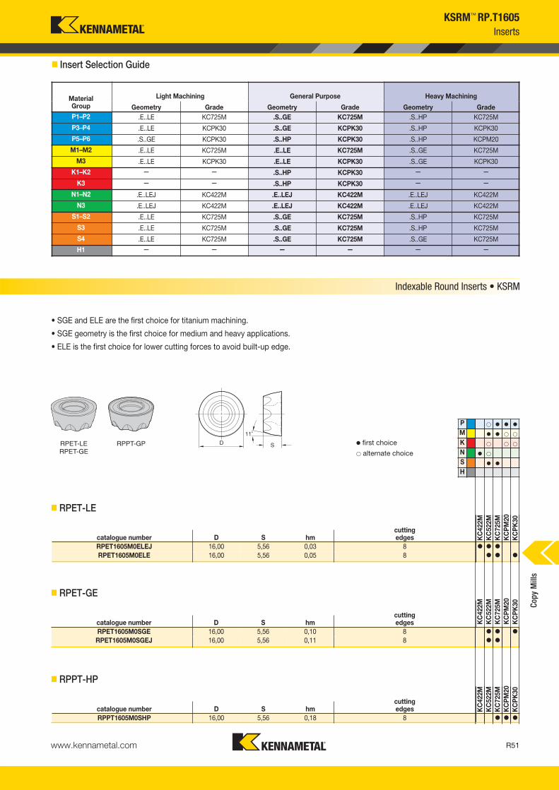
www.kennametal.com R51
KSRM™ RP.T1605Inserts
� Insert Selection Guide
MaterialGroup
Light Machining General Purpose Heavy Machining
Geometry Grade Geometry Grade Geometry GradeP1–P2 .E..LE KC725M .S..GE KC725M .S..HP KC725M
P3–P4 .E..LE KCPK30 .S..GE KCPK30 .S..HP KCPK30
P5–P6 .S..GE KCPK30 .S..HP KCPK30 .S..HP KCPM20
M1–M2 .E..LE KC725M .E..LE KC725M .S..GE KC725M
M3 .E..LE KCPK30 .E..LE KCPK30 .S..GE KCPK30
K1–K2 — — .S..HP KCPK30 — —
K3 — — .S..HP KCPK30 — —
N1–N2 .E..LEJ KC422M .E..LEJ KC422M .E..LEJ KC422M
N3 .E..LEJ KC422M .E..LEJ KC422M .E..LEJ KC422M
S1–S2 .E..LE KC725M .S..GE KC725M .S..HP KC725M
S3 .E..LE KC725M .S..GE KC725M .S..HP KC725M
S4 .E..LE KC725M .S..GE KC725M .S..GE KC725M
H1 — — — — — —
RPET-LERPET-GE
RPPT-GP
Indexable Round Inserts • KSRM
• SGE and ELE are the first choice for titanium machining.
• SGE geometry is the first choice for medium and heavy applications.
• ELE is the first choice for lower cutting forces to avoid built-up edge.
� first choice� alternate choice
� RPET-LE
catalogue number D S hmcutting edges K
C42
2MK
C52
2MK
C72
5MK
CP
M20
KC
PK
30
RPET1605M0ELEJ 16,00 5,56 0,03 8 � � �
RPET1605M0ELE 16,00 5,56 0,05 8 � � �
� RPET-GE
catalogue number D S hmcutting edges K
C42
2MK
C52
2MK
C72
5MK
CP
M20
KC
PK
30
RPET1605M0SGE 16,00 5,56 0,10 8 � � �
RPET1605M0SGEJ 16,00 5,56 0,11 8 � �
catalogue number D S hmcutting edges K
C42
2MK
C52
2MK
C72
5MK
CP
M20
KC
PK
30
RPPT1605M0SHP 16,00 5,56 0,18 8 � � �
P � � � �
M � � � �
K � � �
N � �
S � �
H
� RPPT-HP
Copy
Mill
s
KM_Master12_R050_R051_METRIC_EN.qxp:Layout 1 3/7/12 9:54 AM Page R51

www.kennametal.comR52
MaterialGroup
KC422M KC522M KC725M KCPM20 KCPK30
P
1 — — — 395 345 325 315 275 255 660 580 535 545 475 4402 — — — 330 290 240 260 230 195 410 370 330 335 305 2753 — — — 305 255 215 240 205 170 370 330 305 305 275 2504 — — — 270 225 180 215 180 145 275 255 230 225 210 1905 — — — 225 200 180 180 160 145 330 300 275 310 275 2556 — — — 200 150 120 160 120 95 230 200 175 190 165 —
M
1 — — — 245 215 200 205 180 165 270 240 205 250 220 1902 — — — 225 190 160 185 160 130 245 215 190 225 195 1703 — — — 170 145 115 140 120 95 195 175 150 175 160 140
K
1 — — — 275 250 220 — — — 435 390 350 355 320 2852 — — — 215 195 180 — — — 345 310 280 280 255 2303 — — — 180 160 145 — — — 290 255 240 235 210 195
N1–2 1285 1135 1050 — — — — — — — — — — — — 3 1135 1050 915 — — — — — — — — — — — —
S
1 — — — 50 45 35 45 35 30 — — — — — — 2 — — — 50 45 35 45 35 30 — — — — — — 3 — — — 60 50 35 55 45 30 — — — — — — 4 — — — 85 60 45 75 55 35 — — — — — —
H 1 — — — — — — — — — — — — — — —
KSRM™ RP.T1605
NOTE: FIRST choice starting speeds are in bold type.As the average chip thickness increases, the speed should be decreased.
InsertGeometry
Programmed Feed per Tooth (fz)as a % of Radial Depth of Cut (ae) Insert
Geometry10% 20% 30% 40% 50–100%.E..LEJ 0,08 0,15 0,23 0,06 0,11 0,17 0,06 0,10 0,15 0,05 0,09 0,14 0,05 0,09 0,14 .E..LEJ.E..LE 0,12 0,26 0,38 0,09 0,19 0,29 0,08 0,17 0,25 0,07 0,16 0,23 0,07 0,15 0,23 .E..LE.S..GE 0,17 0,43 0,68 0,13 0,32 0,51 0,11 0,28 0,44 0,10 0,26 0,41 0,10 0,25 0,41 .S..GE.S..HP 0,17 0,43 0,68 0,13 0,32 0,51 0,11 0,28 0,44 0,10 0,26 0,41 0,10 0,25 0,41 .S..HP
InsertGeometry
Programmed Feed per Tooth (fz)as a % of Radial Depth of Cut (ae) Insert
Geometry10% 20% 30% 40% 50–100%.E..LEJ 0,10 0,17 0,26 0,07 0,13 0,20 0,06 0,11 0,17 0,06 0,11 0,16 0,06 0,10 0,16 .E..LEJ.E..LE 0,14 0,30 0,44 0,10 0,22 0,33 0,09 0,19 0,29 0,09 0,18 0,27 0,08 0,18 0,27 .E..LE.S..GE 0,20 0,49 0,79 0,15 0,37 0,59 0,13 0,32 0,51 0,12 0,30 0,48 0,12 0,29 0,47 .S..GE.S..HP 0,20 0,49 0,79 0,15 0,37 0,59 0,13 0,32 0,51 0,12 0,30 0,48 0,12 0,29 0,47 .S..HP
InsertGeometry
Programmed Feed per Tooth (fz)as a % of Radial Depth of Cut (ae) Insert
Geometry10% 20% 30% 40% 50–100%.E..LEJ 0,13 0,23 0,34 0,10 0,17 0,26 0,08 0,15 0,22 0,08 0,14 0,21 0,08 0,14 0,20 .E..LEJ.E..LE 0,18 0,39 0,58 0,14 0,29 0,43 0,12 0,25 0,38 0,11 0,24 0,35 0,11 0,23 0,35 .E..LE.S..GE 0,26 0,64 1,04 0,19 0,48 0,77 0,17 0,42 0,67 0,16 0,39 0,63 0,15 0,38 0,61 .S..GE.S..HP 0,26 0,64 1,04 0,19 0,48 0,77 0,17 0,42 0,67 0,16 0,39 0,63 0,15 0,38 0,61 .S..HP
InsertGeometry
Programmed Feed per Tooth (fz)as a % of Radial Depth of Cut (ae) Insert
Geometry10% 20% 30% 40% 50–100%.E..LEJ 0,18 0,31 0,47 0,13 0,23 0,35 0,11 0,20 0,30 0,11 0,19 0,28 0,10 0,19 0,28 .E..LEJ.E..LE 0,25 0,53 0,80 0,19 0,40 0,59 0,16 0,35 0,52 0,15 0,32 0,48 0,15 0,32 0,47 .E..LE.S..GE 0,35 0,88 1,42 0,26 0,66 1,05 0,23 0,57 0,92 0,21 0,54 0,86 0,21 0,52 0,84 .S..GE.S..HP 0,35 0,88 1,42 0,26 0,66 1,05 0,23 0,57 0,92 0,21 0,54 0,86 0,21 0,52 0,84 .S..HP
NOTE: Use “Light Machining” values as starting feed rate.
� Recommended Starting Speeds [m/min]
� Recommended Starting Feeds [mm] Light Machining
General Purpose
Heavy Machining
At 8,00 Axial Depth of Cut (ap)
At 4,00 Axial Depth of Cut (ap)
At 2,00 Axial Depth of Cut (ap)
At 1,00 Axial Depth of Cut (ap)
Recommended Starting Speeds and FeedsCo
py M
ills
KM_Master12_R052_R053_METRIC_EN.qxp:Layout 1 3/7/12 9:54 AM Page R52
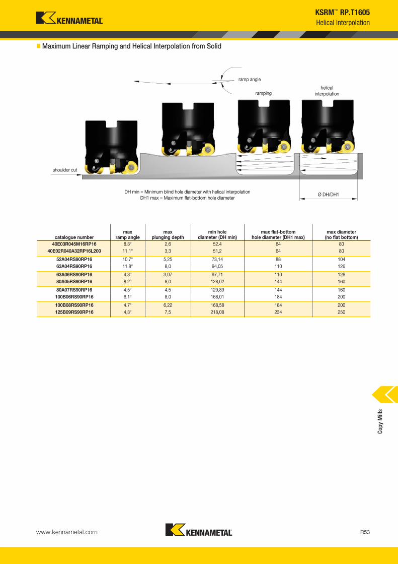
www.kennametal.com R53
catalogue numbermax
ramp anglemax
plunging depthmin hole
diameter (DH min)max flat-bottom
hole diameter (DH1 max)max diameter
(no flat bottom)40E03R045M16RP16 8.3° 2,6 52.4 64 80
40E02R040A32RP16L200 11.1° 3,3 51,2 64 80
52A04RS90RP16 10.7° 5,25 73,14 88 10463A04RS90RP16 11.8° 8,0 94,05 110 126
63A06RS90RP16 4.3° 3,07 97,71 110 12680A05RS90RP16 8.2° 8,0 128,02 144 160
80A07RS90RP16 4.5° 4,5 129,89 144 160100B06RS90RP16 6.1° 8,0 168,01 184 200
100B08RS90RP16 4.7° 6,22 168,58 184 200125B09RS90RP16 4,3° 7,5 218,08 234 250
KSRM™ RP.T1605Helical Interpolation
ramp angle
shoulder cut
rampinghelical
interpolation
Ø DH/DH1DH min = Minimum blind hole diameter with helical interpolationDH1 max = Maximum flat-bottom hole diameter
� Maximum Linear Ramping and Helical Interpolation from Solid
Copy
Mill
s
KM_Master12_R052_R053_METRIC_EN.qxp:Layout 1 3/7/12 9:54 AM Page R53

www.kennametal.comR54
order number catalogue number D1 max D1 D D4 D6 L Ap1 max Zmax
ramp angle kg max RPM insert 13095646 63A04RS90RC20C 63 43 22 — 50 50 10,0 4 0.80° 0,62 26000 RCGT2006M0___3095647 80A05RS90RC20C 80 60 27 — 60 50 10,0 5 0.80° 0,89 22000 RCGT2006M0___
3095648 100B05RS90RC20C 100 80 32 — 80 63 10,0 5 0.80° 2,16 18000 RCGT2006MO___3095649 100B06RS90RC20C 100 80 32 — 80 63 10,0 6 0.90° 2,11 18000 RCGT2006MO___
3095650 125B06RS90RC20C 125 105 40 — 90 63 10,0 6 0.60° 2,96 15000 RCGT2006M0___3095651 160C07RS90RC20C 160 140 40 67 100 63 10,0 7 0.50° 3,90 14000 RCGT2006M0___
3095652 160C08RS90RC20C 160 140 40 67 100 63 10,0 8 0.50° 3,87 14000 RCGT2006M0___3095653 200C09RS90RC20C 200 180 60 102 130 63 10,0 9 0.40° 5,77 12500 RCGT2006M0___
D1 maxinsert screw Nm
Torx wrench
anti-rotationscrew
coolant cap assembly
SHCS with coolant groove
coolant lock screw assembly
63 MS1162 5,0 TT25 S2160 — MS1242CG —80 MS1162 5,0 TT25 S2160 — MS2190CG —
100 MS1162 5,0 TT25 S2160 — — MS2188C125 MS1162 5,0 TT25 S2160 — — MS2187C
160 MS1162 5,0 TT25 S2160 MCCM16001 — —200 MS1162 5,0 TT25 S2160 MCC080001 — —
KSRM™ RC.T2006Face Mills • Metric
• Diameter range from 63–200mm.
• Engineered for roughing titanium with large depths of cutthrough positive geometry inserts.
• Anti-rotation feature allows up to six indexable rotations.
� Face Mills
� Spare Parts
Copy
Mill
s
KM_Master12_R054_R055_METRIC_EN.qxp:Layout 1 3/7/12 9:53 AM Page R54

www.kennametal.com R55
Inserts
� Insert Selection Guide
MaterialGroup
Light Machining General Purpose Heavy Machining
Geometry Grade Geometry Grade Geometry GradeP1–P2 .E..LF KC725M .S..GF KC725M .S..HF KC725M
P3–P4 .S..GF KC522M .S..GF KC725M .S..HF KCPK30
P5–P6 .S..GF KC522M .S..HF KCPK30 .S..HF KCPK30
M1–M2 .E..LF KC725M .S..GF KC725M .S..HF KC725M
M3 .E..LF KC725M .S..GF KC725M .S..HF KCPK30
K1–K2 — — .S..HF KCPK30 — —
K3 — — .S..HF KCPK30 — —
N1–N2 — — — — — —
N3 — — — — — —
S1–S2 .E..LF KC725M .S..GF KC725M .S..HF KC725M
S3 .E..LF KC725M .S..GF KC725M .S..HF KC725M
S4 .E..LF KC725M .S..GF KC725M .S..HF KC725M
H1 — — — — — —
P � � �
M � � �
K �
NS � �
H
catalogue number D S hmcutting edges K
C52
2MK
C72
5MK
CP
K30
RCGT2006M0ELF 20,00 6,35 0,04 6 �
catalogue number D S hmcutting edges K
C52
2MK
C72
5MK
CP
K30
RCGT2006M0SGF 20,00 6,35 0,10 6 � �
catalogue number D S hmcutting edges K
C52
2MK
C72
5MK
CP
K30
RCGT2006M0SHF 20,00 6,35 0,25 6 � �
RCTG-LFRCTG-GFRCTG-HF
� first choice� alternate choice
• ELF is the first choice for lower cutting forces to avoid build-up edge.
• SGF is for general purpose in roughing applications.
• SHF is the first choice for heavy duty.
� RCTG-LF
� RCTG-GF
� RCTG-HF
KSRM™ RC.T2006
Indexable Round Inserts • KSRM
Copy
Mill
s
KM_Master12_R054_R055_METRIC_EN.qxp:Layout 1 3/7/12 9:53 AM Page R55
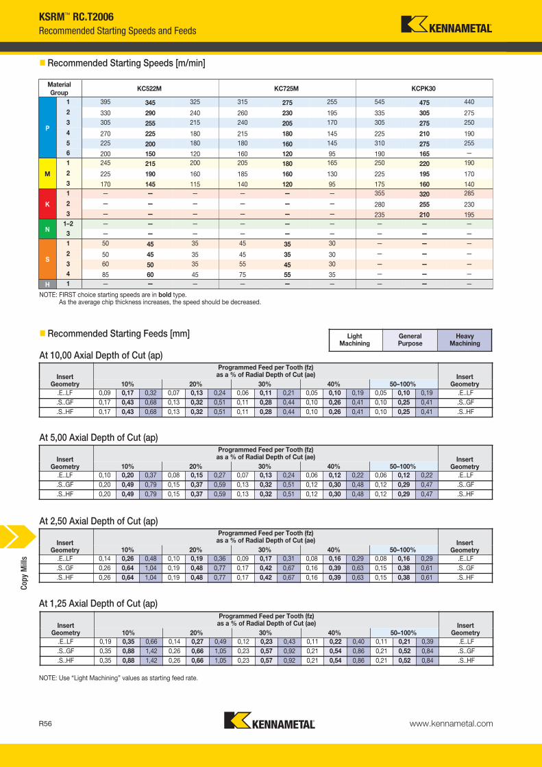
www.kennametal.comR56
KSRM™ RC.T2006
MaterialGroup
KC522M KC725M KCPK30
P
1 395 345 325 315 275 255 545 475 440
2 330 290 240 260 230 195 335 305 2753 305 255 215 240 205 170 305 275 250
4 270 225 180 215 180 145 225 210 1905 225 200 180 180 160 145 310 275 2556 200 150 120 160 120 95 190 165 —
M
1 245 215 200 205 180 165 250 220 190
2 225 190 160 185 160 130 225 195 1703 170 145 115 140 120 95 175 160 140
K
1 — — — — — — 355 320 285
2 — — — — — — 280 255 2303 — — — — — — 235 210 195
N1–2 — — — — — — — — — 3 — — — — — — — — —
S
1 50 45 35 45 35 30 — — —
2 50 45 35 45 35 30 — — —
3 60 50 35 55 45 30 — — — 4 85 60 45 75 55 35 — — —
H 1 — — — — — — — — —
NOTE: FIRST choice starting speeds are in bold type.As the average chip thickness increases, the speed should be decreased.
InsertGeometry
Programmed Feed per Tooth (fz)as a % of Radial Depth of Cut (ae) Insert
Geometry10% 20% 30% 40% 50–100%.E..LF 0,09 0,17 0,32 0,07 0,13 0,24 0,06 0,11 0,21 0,05 0,10 0,19 0,05 0,10 0,19 .E..LF.S..GF 0,17 0,43 0,68 0,13 0,32 0,51 0,11 0,28 0,44 0,10 0,26 0,41 0,10 0,25 0,41 .S..GF.S..HF 0,17 0,43 0,68 0,13 0,32 0,51 0,11 0,28 0,44 0,10 0,26 0,41 0,10 0,25 0,41 .S..HF
InsertGeometry
Programmed Feed per Tooth (fz)as a % of Radial Depth of Cut (ae) Insert
Geometry10% 20% 30% 40% 50–100%.E..LF 0,10 0,20 0,37 0,08 0,15 0,27 0,07 0,13 0,24 0,06 0,12 0,22 0,06 0,12 0,22 .E..LF.S..GF 0,20 0,49 0,79 0,15 0,37 0,59 0,13 0,32 0,51 0,12 0,30 0,48 0,12 0,29 0,47 .S..GF.S..HF 0,20 0,49 0,79 0,15 0,37 0,59 0,13 0,32 0,51 0,12 0,30 0,48 0,12 0,29 0,47 .S..HF
InsertGeometry
Programmed Feed per Tooth (fz)as a % of Radial Depth of Cut (ae) Insert
Geometry10% 20% 30% 40% 50–100%.E..LF 0,14 0,26 0,48 0,10 0,19 0,36 0,09 0,17 0,31 0,08 0,16 0,29 0,08 0,16 0,29 .E..LF.S..GF 0,26 0,64 1,04 0,19 0,48 0,77 0,17 0,42 0,67 0,16 0,39 0,63 0,15 0,38 0,61 .S..GF.S..HF 0,26 0,64 1,04 0,19 0,48 0,77 0,17 0,42 0,67 0,16 0,39 0,63 0,15 0,38 0,61 .S..HF
InsertGeometry
Programmed Feed per Tooth (fz)as a % of Radial Depth of Cut (ae) Insert
Geometry10% 20% 30% 40% 50–100%.E..LF 0,19 0,35 0,66 0,14 0,27 0,49 0,12 0,23 0,43 0,11 0,22 0,40 0,11 0,21 0,39 .E..LF.S..GF 0,35 0,88 1,42 0,26 0,66 1,05 0,23 0,57 0,92 0,21 0,54 0,86 0,21 0,52 0,84 .S..GF.S..HF 0,35 0,88 1,42 0,26 0,66 1,05 0,23 0,57 0,92 0,21 0,54 0,86 0,21 0,52 0,84 .S..HF
NOTE: Use “Light Machining” values as starting feed rate.
Light Machining
General Purpose
Heavy Machining
� Recommended Starting Speeds [m/min]
� Recommended Starting Feeds [mm]
Recommended Starting Speeds and Feeds
At 10,00 Axial Depth of Cut (ap)
At 5,00 Axial Depth of Cut (ap)
At 2,50 Axial Depth of Cut (ap)
At 1,25 Axial Depth of Cut (ap)
Copy
Mill
s
KM_Master12_R056_R057_METRIC_EN.qxp:Layout 1 3/7/12 10:14 AM Page R56
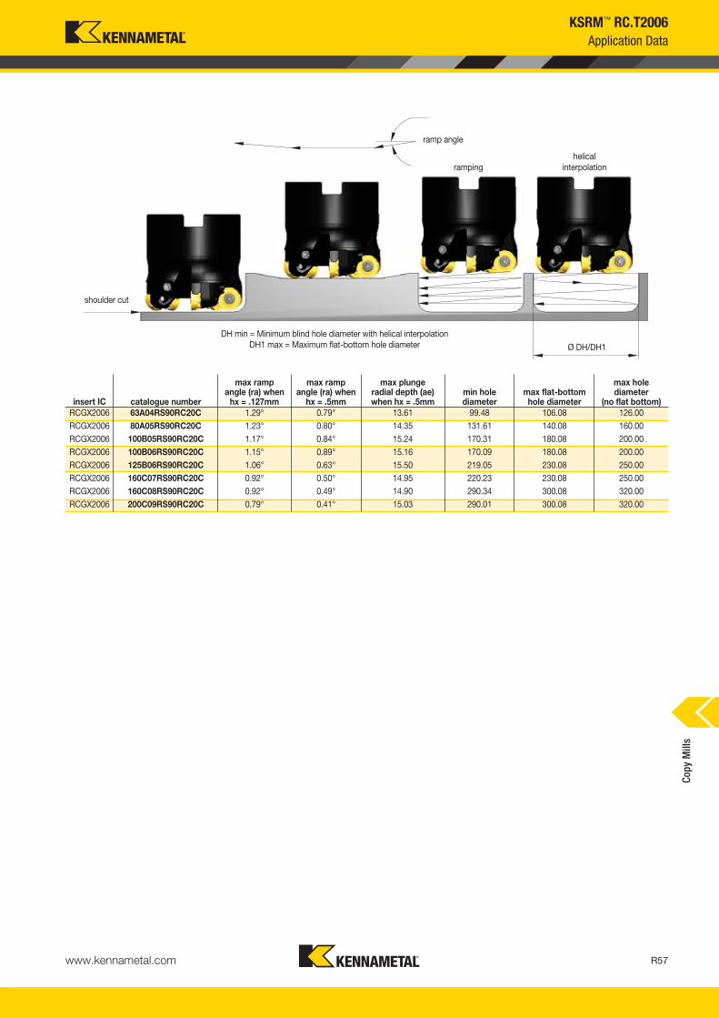
ramp angle
shoulder cut
rampinghelical
interpolation
Ø DH/DH1
DH min = Minimum blind hole diameter with helical interpolationDH1 max = Maximum flat-bottom hole diameter
insert IC catalogue number
max ramp angle (ra) when
hx = .127mm
max ramp angle (ra) when
hx = .5mm
max plunge radial depth (ae) when hx = .5mm
min hole diameter
max flat-bottomhole diameter
max hole diameter
(no flat bottom)RCGX2006 63A04RS90RC20C 1.29° 0.79° 13.61 99.48 106.08 126.00RCGX2006 80A05RS90RC20C 1.23° 0.80° 14.35 131.61 140.08 160.00RCGX2006 100B05RS90RC20C 1.17° 0.84° 15.24 170.31 180.08 200.00RCGX2006 100B06RS90RC20C 1.15° 0.89° 15.16 170.09 180.08 200.00RCGX2006 125B06RS90RC20C 1.06° 0.63° 15.50 219.05 230.08 250.00RCGX2006 160C07RS90RC20C 0.92° 0.50° 14.95 220.23 230.08 250.00RCGX2006 160C08RS90RC20C 0.92° 0.49° 14.90 290.34 300.08 320.00RCGX2006 200C09RS90RC20C 0.79° 0.41° 15.03 290.01 300.08 320.00
KSRM™ RC.T2006Application Data
Copy
Mill
s
www.kennametal.com R57
KM_Master12_R056_R057_METRIC_EN.qxp:Layout 1 3/7/12 10:14 AM Page R57

Primary ApplicationSpecially developed for machining titanium. Beyond BLAST KSRM platform boosts your productivity with its new and revolutionary technology, PCT (Precision Coolant Technology), enabling consistent performance and providing outstanding metal removal rates and longer tool life.
Features and Benefits
Beyond BLAST™ KSRM™ • Next Generation Round Inserts with Through Coolant
www.kennametal.comR58
Platform Features
Channeling coolant through the insert.
Anti-rotation feature with six indexes.
High positive topography with strong cutting edges.
High clearance on the cutters and inserts.
Functions
Increase productivity, tool life, and chip control.
Superior productivity and better insertutilization/cost per edge.
Long tool life and better MRR.
Able to convert all milling applications.
To learn more, scan here. For instructions on how to scan, please see page xxix.
KM_Master12_R058_R059_METRIC_EN.qxp:Layout 1 3/7/12 9:57 AM Page R58

www.kennametal.com R59
order number catalogue number D1 max D1 D D6 L Ap1 max Z kg max RPM insert 14109173 KSRM63A04RC20BB 63 43 22 50 50 10,0 4 0,54 21900 RCGX2006M0__4109174 KSRM80A05RC20BB 80 60 27 60 50 10,0 5 0,83 18500 RCGX2006M0__
4109175 KSRM100B05RC20BB 100 80 32 80 50 10,0 5 1,45 16000 RCGX2006M0__4109176 KSRM100B06RC20BB 100 80 32 80 50 10,0 6 1,43 16000 RCGX2006M0__
4109177 KSRM125B06RC20BB 125 105 40 90 63 10,0 6 2,90 14000 RCGX2006M0__4109178 KSRM125B07RC20BB 125 105 40 90 63 10,0 7 2,90 14000 RCGX2006M0__
4109179 KSRM160C07RC20BB 160 140 40 90 63 10,0 7 3,34 12100 RCGX2006M0__4109180 KSRM160C08RC20BB 160 140 40 90 63 10,0 8 3,30 12100 RCGX2006M0__
4109181 KSRM200C09RC20BB 200 180 60 130 63 10,0 9 5,49 10700 RCGX2006M0__
D1 maxinsert screw Nm
universal bit torque driver
drive bit
coolant lock screw assembly
coolant shower plate assembly
socket-head cap screwwith coolant groove
63 MS1162 5,0 KPTW45 BT25L50 — — MS1234CG80 MS1162 5,0 KPTW45 BT25L50 — — MS2190CG
100 MS1162 5,0 KPTW45 BT25L50 MS2195C — —125 MS1162 5,0 KPTW45 BT25L50 MS2187C — —
160 MS1162 5,0 KPTW45 BT25L50 — MCCM16001 —200 MS1162 5,0 KPTW45 BT25L50 — MCC080001 —
Beyond BLAST™ KSRM™
Face Mills • BB KSRM • RCGX2006...
• Use PCT technology; coolant through the insert.
• Engineered to provide the maximum performance in titanium machining.
• Anti-rotation feature allows up to six indexable rotations.
• Pocketing, ramping, plunging, and helical interpolation capabilities.
� Face Mills • Metric
� Spare Parts
Copy
Mill
s
KM_Master12_R058_R059_METRIC_EN.qxp:Layout 1 3/7/12 9:57 AM Page R59

www.kennametal.comR60
order number catalogue number D1 max D1 D D6 L Ap1 max Z kg max RPM insert 14137791 KSRM80A05RC20BB-J 80 60 25 56 50 10,0 5 0,84 18500 RCGX2006M0__4137792 KSRM100B06RC20BB-J 100 80 32 73 50 10,0 6 1,26 16000 RCGX2006M0__
4137793 KSRM125B07RC20BB-J 125 105 38 97 63 10,0 7 3,03 14000 RCGX2006M0__4137794 KSRM160B08RC20BB-J 160 140 51 127 63 10,0 8 5,22 12100 RCGX2006M0__
4137795 KSRM200C09RC20BB-J 200 180 48 130 63 10,0 9 6,06 10700 RCGX2006M0__
D1 maxinsert screw Nm
universal bit torque driver
drive bit
coolant lock screw assembly
coolant shower plate assembly
socket-head cap screwwith coolant groove
80 MS1162 5,0 KPTW45 BT25L50 — — MS2190CG100 MS1162 5,0 KPTW45 BT25L50 MS2220C — —
125 MS1162 5,0 KPTW45 BT25L50 — — —160 MS1162 5,0 KPTW45 BT25L50 — — —
200 MS1162 5,0 KPTW45 BT25L50 — MCC080001 —
Beyond BLAST™ KSRM™
Face Mills JIS • BB KSRM • RCGX2006...
• Use PCT technology; coolant through the insert.
• Engineered to provide the maximum performance in titanium machining.
• Anti-rotation feature allows up to six indexable rotations.
• Pocketing, ramping, plunging, and helical interpolation capabilities.
� Face Mills • JIS (Japanese Industry Standard)
� Spare Parts
Geometry for medium and heavy machining
S
Geometry for light and medium machining
S
Best-in-Class Performance Booster in Machining Titanium
Copy
Mill
s
-ELF -SGF
KM_Master12_R060_R061_METRIC_EN.qxp:Layout 1 3/7/12 9:57 AM Page R60

www.kennametal.com R61
Beyond BLAST™ KSRM™
Inserts
� Insert Selection Guide
MaterialGroup
Light Machining General Purpose Heavy Machining
Geometry Grade Geometry Grade Geometry GradeP1–P2 — — — — — —
P3–P4 — — — — — —
P5–P6 — — — — — —
M1–M2 — — — — — —
M3 — — — — — —
K1–K2 — — — — — —
K3 — — — — — —
N1–N2 — — — — — —
N3 — — — — — —
S1–S2 — — — — — —
S3 — — — — — —
S4 .E..LF KC725M .S..GF KC725M .S..GF KC725M
H1 — — — — — —
RCGX-LFRCGX-GF
Indexable Insert • BB KSRM
• Revolutionary concept of channeling coolant through the insert.
• Engineered to provide the maximum performance in titanium machining.
• ELF geometry for lower cutting forces to avoid built-up edge.
• SGF in the first choice for higher chip load and heavy applications.
PMKNS �
H
� first choice� alternate choice
� RCGX-LF and -GF
catalogue number D S hmcutting edges K
C72
5M
RCGX2006M0ELF 20,00 6,35 0,08 6 �
RCGX2006M0SGF 20,00 6,35 0,10 6 �
Copy
Mill
s
KM_Master12_R060_R061_METRIC_EN.qxp:Layout 1 3/7/12 9:57 AM Page R61

www.kennametal.comR62
MaterialGroup
KC725M
P
1 — — — 2 — — — 3 — — — 4 — — — 5 — — — 6 — — —
M
1 — — — 2 — — — 3 — — —
K
1 — — — 2 — — — 3 — — —
N1 — — — 2 — — —
S
1 — — — 2 — — — 3 — — — 4 75 55 35
H
1 — — — 2 — — — 3 — — —
Recommended Starting Speeds and Feeds
� Recommended Starting Speeds [m/min]
NOTE: FIRST choice starting speeds are in bold type.As the average chip thickness increases, the speed should be decreased.
InsertGeometry
Programmed Feed per Tooth (fz)as a % of Radial Depth of Cut (ae) Insert
Geometry10% 20% 30% 40% 50–100%.E..LF 0,17 0,36 0,54 0,13 0,27 0,40 0,11 0,24 0,35 0,10 0,22 0,33 0,10 0,22 0,32 .E..LF.S..GF 0,17 0,43 0,67 0,13 0,32 0,50 0,11 0,28 0,44 0,10 0,26 0,41 0,10 0,25 0,40 .S..GF
InsertGeometry
Programmed Feed per Tooth (fz)as a % of Radial Depth of Cut (ae) Insert
Geometry10% 20% 30% 40% 50–100%.E..LF 0,20 0,42 0,62 0,15 0,31 0,46 0,13 0,27 0,40 0,12 0,25 0,38 0,12 0,25 0,37 .E..LF.S..GF 0,20 0,49 0,78 0,15 0,37 0,58 0,13 0,32 0,50 0,12 0,30 0,47 0,12 0,29 0,46 .S..GF
InsertGeometry
Programmed Feed per Tooth (fz)as a % of Radial Depth of Cut (ae) Insert
Geometry10% 20% 30% 40% 50–100%.E..LF 0,26 0,55 0,81 0,19 0,41 0,61 0,17 0,36 0,53 0,16 0,33 0,49 0,15 0,33 0,48 .E..LF.S..GF 0,26 0,64 1,02 0,19 0,48 0,76 0,17 0,42 0,66 0,16 0,39 0,62 0,15 0,38 0,60 .S..GF
InsertGeometry
Programmed Feed per Tooth (fz)as a % of Radial Depth of Cut (ae) Insert
Geometry10% 20% 30% 40% 50–100%.E..LF 0,35 0,75 1,12 0,26 0,56 0,83 0,23 0,49 0,72 0,21 0,46 0,67 0,21 0,45 0,66 .E..LF.S..GF 0,35 0,88 1,40 0,26 0,66 1,04 0,23 0,57 0,90 0,21 0,54 0,84 0,21 0,52 0,83 .S..GF
Light Machining
General Purpose
Heavy Machining
Beyond BLAST™ KSRM™
NOTE: Use “ Light Machining” values as starting feed rate.
� Recommended Starting Feeds [mm]
At 10,00 Axial Depth of Cut (ap)
At 5,00 Axial Depth of Cut (ap)
At 2,50 Axial Depth of Cut (ap)
At 1,25 Axial Depth of Cut (ap)Copy
Mill
s
KM_Master12_R062_R063_METRIC_EN.qxp:Layout 1 3/7/12 9:57 AM Page R62

www.kennametal.com R63
insert IC catalogue numbermax
ramp anglemax
ramp depthmax
plunging depthmin hole
diameter (DH min)max flat-bottom
hole diameter (DH1 max)max diameter
(no flat bottom)RCGX2006 KSRM63A04RC20BB 1,29° 0,88 1,45 97,99 106,08 126,00RCGX2006 KSRM80A05RC20BB 1,23° 1,19 1,82 130,70 140,08 160,00
RCGX2006 KSRM100B05RC20BB 1,17° 1,53 2,16 169,53 180,08 200,00RCGX2006 KSRM100B06RC20BB 1,15° 1,51 2,13 169,61 180,08 200,00
RCGX2006 KSRM125B06RC20BB 1,06° 1,84 2,44 218,61 230,08 250,00RCGX2006 KSRM125B07RC20BB 1,05° 1,81 2,41 218,68 230,08 250,00
RCGX2006 KSRM160C07RC20BB 0,92° 2,15 2,71 287,75 300,08 320,00RCGX2006 KSRM160C08RC20BB 0,92° 2,14 2,69 287,78 300,08 320,00
RCGX2006 KSRM200C09RC20BB 0,79° 2,40 2,90 367,16 380,08 400,00RCGX2006 KSRM80A05RC20BB-J 1,23° 1,19 1,82 130,70 140,08 160,00
RCGX2006 KSRM100B06RC20BB-J 1,15° 1,51 2,13 169,61 180,08 200,00RCGX2006 KSRM125B07RC20BB-J 1,05° 1,81 2,41 218,68 230,08 250,00
RCGX2006 KSRM160C08RC20BB-J 0,92° 2,14 2,69 287,78 300,08 320,00RCGX2006 KSRM200C09RC20BB-J 0,79° 2,40 2,90 367,16 380,08 400,00
Beyond BLAST™ KSRM™
Application Data
� Ramping and Helical Interpolation Values from Solid
ramp angle
shoulder cut
rampinghelical
interpolation
Ø DH/DH1DH min = Minimum blind hole diameter with helical interpolationDH1 max = Maximum flat-bottom hole diameter
Copy
Mill
s
KM_Master12_R062_R063_METRIC_EN.qxp:Layout 1 3/7/12 9:57 AM Page R63

KDMB™ and KDMT™ • Indexable Copy Insert Platforms
Primary ApplicationBall nose and toroidal styles for roughing and finishing operations. Engineered with the ultimate technologies and supported with a wide range of diameters and insert styles, this platform provides exceptional performance and productivity. The new High-Feed insert style provides the highest metal removal rates for roughing applications.
Features and Benefits
Longer Tool Life and Improved Geometries• Longer tool life for finishing operations, up to 63 HRC.
• High-accuracy inserts and holders: overall runout ± 0,01mm.
• Improved geometries for roughing and finishing operations.
• Smaller diameters from 6mm to replace SCEM, setting a more productive machining process.
Superior Productivity• Due to the new helical geometry, we obtain better surface quality.
• New ultra-grain grade for outstanding tool life.
• Diameters 6mm and 8mm natural replacement for SEM tools.
• Better cost per edge.
Usability and Flexibility• Wide diameter range, from 6–32mm, enables it to be applied across
a wide range of machining conditions.
• Many workpiece materials are possible — from hardened steel to aluminium.
• Large holder style offering: screw-on, cylindrical, and tapered steel and carbide holders.
www.kennametal.comR64
KM_Master12_R064_R065_METRIC_EN.qxp:Layout 1 3/7/12 9:52 AM Page R64

www.kennametal.com R65
KDMB™
Indexable Ball Nose Finisher
• Available diameters: 12–25mm.
• High precision and runout accuracy.
• Suitable for roughing and finishing operations.
� Screw-On End Mills
order number catalogue number D1 D D3 L L2 Ap1 max Z Z Ucoolant supply
max ramp angle max RPM insert 1
1918676 KDMB12R130A12SN 12 12 11 130 32 6,0 1 2 No 3.0° 40000 KDMB12..1918677 KDMB12R150A12SN 12 12 11 150 46 6,0 1 2 No 3.0° 40000 KDMB12..
1918678 KDMB16R140A16SN 16 16 14 140 35 8,0 1 2 No 3.0° 40000 KDMB16..1918679 KDMB16R160A16SN 16 16 14 160 53 8,0 1 2 No 3.0° 40000 KDMB16..
1918680 KDMB20R160A20SN 20 20 18 160 45 10,0 1 2 No 3.0° 40000 KDMB20..1918681 KDMB20R175A20SN 20 20 18 175 61 10,0 1 2 No 3.0° 40000 KDMB20..
1918682 KDMB25R160A25SN 25 25 22 160 45 12,5 1 2 No 3.0° 40000 KDMB25..1918683 KDMB25R190A25SN 25 25 22 190 70 12,5 1 2 No 3.0° 40000 KDMB25..
1918684 KDMB32R175A32SN 32 32 29 175 56 16,0 1 2 No 3.0° 40000 KDMB32..1918685 KDMB32R210A32SN 32 32 29 210 80 16,0 1 2 No 3.0° 40000 KDMB32..
• Available diameters: 12–32mm.
• High precision and runout accuracy.
• Can be used with heat shrink technology, h6 shank tolerance.
• Suitable for roughing and finishing operations.
� Necked End Mills • Cylindrical Shank • Steel
� Spare Parts
D1insert screw Nm
Torx wrench
12 193.393 4,0 KT2016 193.392 5,0 KT20
20 193.391 6,0 KT2025 193.390 6,5 KT30
32 193.389 6,5 KT30
order number catalogue number D1 D DPM G3X L2 Ap1 max Z Z Umax
ramp angle max RPM insert 11918651 KDMB12R026M08SN 12 13 8,5 M8 26 6,0 1 2 3.0° 40000 KDMB12..1918652 KDMB16R026M08SN 16 13 8,5 M8 26 8,0 1 2 3.0° 40000 KDMB16..
1918663 KDMB20R030M10SN 20 18 10,5 M10 30 10,0 1 2 3.0° 40000 KDMB20..1918664 KDMB25R040M12SN 25 21 12,5 M12 40 12,5 1 2 3.0° 30000 KDMB25..
Copy
Mill
s
KM_Master12_R064_R065_METRIC_EN.qxp:Layout 1 3/7/12 9:52 AM Page R65

www.kennametal.comR66
order number catalogue number D1 D L L2 Ap1 max Z Z Ucoolant supply
max ramp angle max RPM insert 1
1918669 KDMB08R140A08ST 8 12 140 50 4,0 1 2 No 3.0° 40000 KDMB08..1918670 KDMB10R150A10ST 10 12 150 34 5,0 1 2 No 3.0° 40000 KDMB10..
1918671 KDMB12R160A12ST 12 16 160 60 6,0 1 2 No 3.0° 40000 KDMB12..1918672 KDMB16R175A16ST 16 20 175 67 8,0 1 2 No 3.0° 40000 KDMB16..
1918673 KDMB20R190A20ST 20 25 190 80 10,0 1 2 No 3.0° 40000 KDMB20..1918674 KDMB25R210A25ST 25 32 210 100 12,5 1 2 No 3.0° 40000 KDMB25..
KDMB™
Indexable Ball Nose Finisher
• Available diameters: 8–25mm.
• High precision and runout accuracy.
• Can be used with heat shrink technology, h6 shank tolerance.
• Suitable for roughing and finishing operations.
• Tapered version ideal for 5-axis applications.
� Tapered End Mills • Cylindrical Shank • Steel
� Spare Parts
D1insert screw Nm
Torx wrench
8 193.395 2,0 KT810 193.394 3,0 KT15
12 193.393 4,0 KT2016 193.392 5,0 KT20
20 193.391 6,0 KT2025 193.390 6,5 KT30
Copy
Mill
s
KM_Master12_R066_R067_METRIC_EN.qxp:Layout 1 3/7/12 9:52 AM Page R66
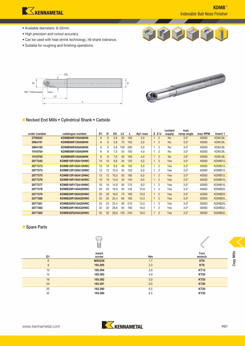
www.kennametal.com R67
D1insert screw Nm
Torx wrench
6 MS2236 1,7 KT68 193.395 2,0 KT8
10 193.394 3,0 KT1512 193.393 4,0 KT20
16 193.392 5,0 KT2020 193.391 6,0 KT20
25 193.390 6,5 KT3032 193.389 6,5 KT30
KDMB™
Indexable Ball Nose Finisher
• Available diameters: 6–32mm.
• High precision and runout accuracy.
• Can be used with heat shrink technology, h6 shank tolerance.
• Suitable for roughing and finishing operations.
� Necked End Mills • Cylindrical Shank • Carbide
� Spare Parts
order number catalogue number D1 D D3 L2 L Ap1 max Z Z Ucoolant supply
max ramp angle max RPM insert 1
3700622 KDMB06R100A06HN 6 6 5,8 20 100 3,0 1 2 No 3.0° 40000 KDM.06..3964191 KDMB06R150A06HN 6 6 5,8 70 150 3,0 1 2 No 3.0° 40000 KDM.06..
3964192 KDMB06R200A06HN 6 6 5,8 100 200 3,0 1 2 No 3.0° 40000 KDM.06..1918704 KDMB08R100A08HN 8 8 7,0 25 100 4,0 1 2 No 3.0° 40000 KDM.08..
1918705 KDMB08R150A08HN 8 8 7,0 40 150 4,0 1 2 No 3.0° 40000 KDM.08..2877242 KDMB10R120A10HNC 10 10 8,8 34 120 5,0 1 2 Yes 3.0° 40000 KDMB10..
2877373 KDMB10R150A10HNC 10 10 8,8 49 150 5,0 1 2 Yes 3.0° 40000 KDMB10..2877374 KDMB12R120A12HNC 12 12 10,5 35 120 6,0 1 2 Yes 3.0° 40000 KDMB12..
2877375 KDMB12R160A12HNC 12 12 10,5 50 160 6,0 1 2 Yes 3.0° 40000 KDMB12..2877376 KDMB16R140A16HNC 16 16 14,0 40 140 8,0 1 2 Yes 3.0° 40000 KDMB16..
2877377 KDMB16R175A16HNC 16 16 14,0 55 175 8,0 1 2 Yes 3.0° 40000 KDMB16..2877378 KDMB20R140A20HNC 20 20 18,0 50 140 10,0 1 2 Yes 3.0° 40000 KDMB20..
2877379 KDMB20R190A20HNC 20 20 18,0 75 190 10,0 1 2 Yes 3.0° 40000 KDMB20..2877380 KDMB25R160A25HNC 25 25 22,4 60 160 12,5 1 2 Yes 3.0° 30000 KDMB25..
2877381 KDMB25R210A25HNC 25 25 22,4 90 210 12,5 1 2 Yes 3.0° 30000 KDMB25..2877382 KDMB32R190A32HNC 32 32 28,6 65 190 16,0 1 2 Yes 3.0° 30000 KDMB32..
2877383 KDMB32R240A32HNC 32 32 28,6 105 240 16,0 1 2 Yes 3.0° 30000 KDMB32..
Copy
Mill
s
KM_Master12_R066_R067_METRIC_EN.qxp:Layout 1 3/7/12 9:52 AM Page R67

www.kennametal.comR68
order number catalogue number D1 D BHTCA L2 L Ap1 max Z Z Ucoolant supply
max ramp angle max RPM insert 1
3964257 KDMB06R90A08HN 6 8 1.8° 40 90 3,0 1 2 No 3.0° 40000 KDM.06..3964258 KDMB08R100A10HN 8 10 1.3° 60 100 4,0 1 2 No 3.0° 40000 KDM.08..
3964259 KDMB08R150A10HN 8 10 1.0° 90 150 4,0 1 2 No 3.0° 40000 KDM.08..3964260 KDMB10R100A12HNC 10 12 1.3° 60 100 5,0 1 2 Yes 3.0° 40000 KDMB10..
3964261 KDMB10R150A12HNC 10 12 1.0° 90 150 5,0 1 2 Yes 3.0° 40000 KDMB10..3964262 KDMB12R120A16HNC 12 16 2.0° 70 120 6,0 1 2 Yes 3.0° 40000 KDMB12..
3964263 KDMB12R150A16HNC 12 16 1.5° 90 150 6,0 1 2 Yes 3.0° 40000 KDMB12..3964264 KDMB16R140A20HNC 16 20 2.0° 70 140 8,0 1 2 Yes 3.0° 40000 KDMB16..
3964265 KDMB16R175A20HNC 16 20 1.5° 90 175 8,0 1 2 Yes 3.0° 40000 KDMB16..
D1insert screw Nm
Torx wrench
6 MS2236 1,0 KT68 193.395 1,7 KT8
10 193.394 3,0 KT1512 193.393 4,0 KT20
16 193.392 5,0 KT20
KDMB™
Indexable Ball Nose Finisher
• Available diameters: 6–16mm.
• High precision and runout accuracy.
• Can be used with heat shrink technology, h6 shank tolerance.
• Suitable for roughing and finishing operations.
• Tapered version ideal for 5-axis applications.
� Tapered End Mills • Cylindrical Shank • Carbide
� Spare Parts
Copy
Mill
s
KM_Master12_R068_R069_METRIC_EN.qxp:Layout 1 3/7/12 9:49 AM Page R68

www.kennametal.com R69
KDMB™
Inserts
� Insert Selection Guide
MaterialGroup
Light Machining General Purpose Heavy Machining
Geometry Grade Geometry Grade Geometry GradeP1–P2 .E..GP KC515M .E..GP KC515M .E..GN KC530MP3–P4 .E..GP KC505M .E..GP KC515M .E..GN KC515MP5–P6 .E..GP KC505M .E..GP KC515M .E..GN KC530MM1–M2 .E..GP KC515M .E..GN KC530M — —
M3 .E..GP KC515M .E..GN KC530M — — K1–K2 .E..GP KC515M .E..GN KC515M .E..GN KC515M
K3 .E..GP KC515M .E..GN KC515M .E..GN KC515MN1–N2 .E..LD K115M .E..LD K115M — —
N3 .E..LD K115M .E..LD K115M — — S1–S2 — — — — — —
S3 — — — — — — S4 .E..LD K115M .E..GP KC515M — — H1 .E..GP KC505M .E..GP KC505M .E..GN KC505M
MaterialGroup
Light Machining General Purpose Heavy Machining
Geometry Grade Geometry Grade Geometry GradeP1–P2 .E..GP KC515M .E..GP KC515M .E..GN KC515MP3–P4 .E..GP KC505M .E..GP KC515M .E..GN KC515MP5–P6 .E..GP KC505M .E..GP KC515M .E..GN KC530MM1–M2 .E..GP KC515M .E..GN KC530M .E..GN KC530M
M3 .E..GP KC515M .E..GN KC530M .E..GN KC530MK1–K2 .E..GP KC515M .E..GN KC515M .E..GN KC515M
K3 .E..GP KC515M .E..GN KC515M .E..GN KC515MN1–N2 .E..LD K115M .E..LD K115M — —
N3 .E..LD K115M .E..LD K115M — — S1–S2 — — — — — —
S3 — — — — — — S4 .E..LD K115M .E..GP KC515M — — H1 .E..GP KC505M .E..GP KC505M .E..GN KC505M
MaterialGroup
Light Machining General Purpose Heavy Machining
Geometry Grade Geometry Grade Geometry GradeP1–P2 .E..GP KC515M .E..GP KC515M .E..HC KC530MP3–P4 .E..GP KC505M .E..GP KC515M .E..HC KC530MP5–P6 .E..GP KC505M .E..GP KC515M .E..HC KC530MM1–M2 .E..GP KC515M .E..HC KC530M .E..HC KC530M
M3 .E..GP KC515M .E..HC KC530M .E..HC KC530MK1–K2 .E..GP KC515M .E..GN KC515M .E..GN KC515M
K3 .E..GP KC515M .E..GN KC515M .E..GN KC515MN1–N2 .E..LD K115M .E..LD K115M — —
N3 .E..LD K115M .E..LD K115M — — S1–S2 — — — — — —
S3 — — — — — — S4 .E..LD K115M .E..GP KC515M .E..HC KC530MH1 .E..GP KC505M .E..GP KC505M .E..GN KC505M
MaterialGroup
Light Machining General Purpose Heavy Machining
Geometry Grade Geometry Grade Geometry GradeP1–P2 .E..GP KC515M .E..GP KC515M — —P3–P4 .E..GP KC505M .E..GP KC515M — —P5–P6 .E..GP KC505M .E..GP KC515M — —M1–M2 .E..GP KC515M — — — —
M3 .E..GP KC515M — — — —K1–K2 .E..GP KC515M .E..GP KC515M — —
K3 .E..GP KC515M .E..GP KC515M — —N1–N2 .E..LD K115M .E..LD K115M — —
N3 .E..LD K115M .E..LD K115M — —S1–S2 — — — — — —
S3 — — — — — —S4 .E..LD K115M .E..GP KC515M — —H1 .E..GP KC505M .E..GP KC505M .E..GN KC505M
KDMB Ball Nose Platform • 12mm
KDMB Ball Nose Platform • 6mm KDMB Ball Nose Platform • 8mm
KDMB Ball Nose Platform • 10mm
KDMB Ball Nose Platform • 16mm KDMB Ball Nose Platform • 20mmCo
py M
ills
KM_Master12_R068_R069_METRIC_EN.qxp:Layout 1 3/7/12 9:49 AM Page R69

www.kennametal.comR70
KDMB™
MaterialGroup
Light Machining General Purpose Heavy Machining
Geometry Grade Geometry Grade Geometry GradeMaterialGroup
Light Machining General Purpose Heavy Machining
Geometry Grade Geometry Grade Geometry GradeP1–P2 .E..GP KC515M .E..GP KC515M .E..HC KC530M
P3–P4 .E..GP KC505M .E..GP KC515M .E..HC KC530M
P5–P6 .E..GP KC505M .E..GP KC515M .E..HC KC530M
M1–M2 .E..GP KC515M .E..HC KC530M .E..HC KC530M
M3 .E..GP KC515M .E..HC KC530M .E..HC KC530M
K1–K2 .E..GP KC515M .E..GN KC515M .E..GN KC515M
K3 .E..GP KC515M .E..GN KC515M .E..GN KC515M
N1–N2 .E..LD K115M .E..LD K115M — —
N3 .E..LD K115M .E..LD K115M — —
S1–S2 — — — — — —
S3 — — — — — —
S4 .E..LD K115M .E..GP KC515M .E..HC KC530M
H1 .E..GP KC505M .E..GP KC505M .E..GN KC505M
Inserts
� Insert Selection Guide
KDMB Ball Nose Platform • 25mm KDMB Ball Nose Platform • 32mm
P1–P2 .E..GP KC515M .E..GP KC515M .E..HC KC530M
P3–P4 .E..GP KC505M .E..GP KC515M .E..HC KC530M
P5–P6 .E..GP KC505M .E..GP KC515M .E..HC KC530M
M1–M2 .E..GP KC515M .E..HC KC530M .E..HC KC530M
M3 .E..GP KC515M .E..HC KC530M .E..HC KC530M
K1–K2 .E..GP KC515M .E..GN KC515M .E..GN KC515M
K3 .E..GP KC515M .E..GN KC515M .E..GN KC515M
N1–N2 .E..LD K115M .E..LD K115M — —
N3 .E..LD K115M .E..LD K115M — —
S1–S2 — — — — — —
S3 — — — — — —
S4 .E..LD K115M .E..GP KC515M .E..HC KC530M
H1 .E..GP KC505M .E..GP KC505M .E..GN KC505M
Insert Style
PSTS geometry with chipbreaker for roughing.Semi-finishing and rest material of steel, cast steel, and high-temperature alloys.
HC Geometry:
High-precision insert with helical geometry for semi-finishing and finishing of steel up to 63 HRC, cast steel, and high-temperature alloys.
GP Geometry:
Geometry with extremely solid cutting edge for roughing cast steel, high-temperaturealloys, and hardened steel up to 60 HRC.
GN Geometry:
roughing, rest material semi-finishing, finishing finishing
Copy
Mill
s
KM_Master12_R070_R071_METRIC_EN.qxp:Layout 1 3/28/12 10:34 AM Page R70

KDMB32M0ERHC 32,00 5,00 16,0 0,10 �
www.kennametal.com R71
P � � �
M � � �
K � � �
N �
S �
H � � �
Indexable Inserts • KDMB...
KDMB-GNKDMB-GPKDMB-LD KDMB-HC
� first choice� alternate choice
KDMB™
catalogue number W S RC hm K11
5MK
C50
5MK
C51
5MK
C53
0M
KDMB06M0ERLD 6,00 1,60 3,0 0,08 �
KDMB08M0ERLD 8,00 2,00 4,0 0,05 �
KDMB10M0ERLD 10,00 2,50 5,0 0,08 �
KDMB12M0ERLD 12,00 2,50 6,0 0,08 �
KDMB16M0ERLD 16,00 3,00 8,0 0,05 �
KDMB20M0ERLD 20,00 3,00 10,0 0,08 �
KDMB25M0ERLD 25,00 4,00 12,5 0,05 �
KDMB32M0ERLD 32,00 5,00 16,0 0,05 �
catalogue number W S RC hm K11
5MK
C50
5MK
C51
5MK
C53
0M
KDMB06M0ERGP 6,00 1,60 3,0 0,06 � �
KDMB08M0ERGP 8,00 2,00 4,0 0,08 � �
KDMB10M0ERGP 10,00 2,50 5,0 0,08 � �
KDMB12M0ERGP 12,00 2,50 6,0 0,06 � �
KDMB16M0ERGP 16,00 3,00 8,0 0,06 � �
KDMB20M0ERGP 20,00 3,00 10,0 0,06 � �
KDMB25M0ERGP 25,00 4,00 12,5 0,08 � �
KDMB32M0ERGP 32,00 5,00 16,0 0,08 � �
catalogue number W S RC hm K11
5MK
C50
5MK
C51
5MK
C53
0M
KDMB06M0ERGN 6,00 1,60 3,0 0,08 �
KDMB08M0ERGN 8,00 2,00 4,0 0,08 � � �
KDMB10M0ERGN 10,00 2,50 5,0 0,08 � � �
KDMB12M0ERGN 12,00 2,50 6,0 0,08 � � �
KDMB16M0ERGN 16,00 3,00 8,0 0,08 � � �
KDMB20M0ERGN 20,00 3,00 10,0 0,08 � � �
KDMB25M0ERGN 25,00 4,00 12,5 0,08 � � �
KDMB32M0ERGN 32,00 5,00 16,0 0,08 � � �
catalogue number W S RC hm K11
5MK
C50
5MK
C51
5MK
C53
0M
KDMB12M0ERHC 12,00 2,50 6,0 0,10 �
KDMB16M0ERHC 16,00 3,00 8,0 0,10 �
KDMB20M0ERHC 20,00 3,00 10,0 0,10 �
KDMB25M0ERHC 25,00 4,00 12,5 0,10 �
� KDMB-LD • High-Precision Positive Geometry • Non-Ferrous and Titanium
� KDMB-GP • High-Precision Helical Geometry and Lower Cutting Forces
� KDMB-GN • High Precision • Extremely Solid Cutting Edge
� KDMB-HC • PSTS Insert Developed • Roughing and Rest Material Operations
Copy
Mill
s
KM_Master12_R070_R071_METRIC_EN.qxp:Layout 1 3/28/12 10:34 AM Page R71
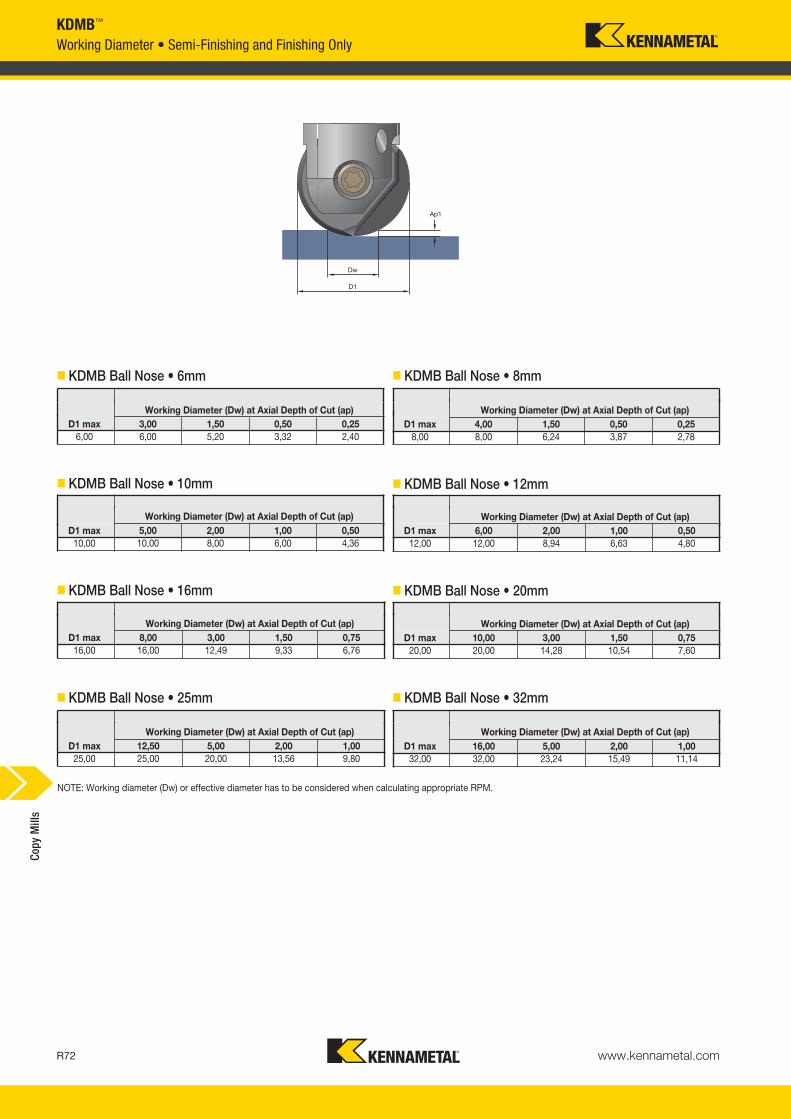
www.kennametal.comR72
Working Diameter (Dw) at Axial Depth of Cut (ap)D1 max 3,00 1,50 0,50 0,25
6,00 6,00 5,20 3,32 2,40
Working Diameter (Dw) at Axial Depth of Cut (ap)D1 max 4,00 1,50 0,50 0,25
8,00 8,00 6,24 3,87 2,78
Working Diameter (Dw) at Axial Depth of Cut (ap)D1 max 5,00 2,00 1,00 0,50
10,00 10,00 8,00 6,00 4,36
Working Diameter (Dw) at Axial Depth of Cut (ap)D1 max 6,00 2,00 1,00 0,50
12,00 12,00 8,94 6,63 4,80
Working Diameter (Dw) at Axial Depth of Cut (ap)D1 max 8,00 3,00 1,50 0,75
16,00 16,00 12,49 9,33 6,76
Working Diameter (Dw) at Axial Depth of Cut (ap)D1 max 10,00 3,00 1,50 0,75
20,00 20,00 14,28 10,54 7,60
Working Diameter (Dw) at Axial Depth of Cut (ap)D1 max 12,50 5,00 2,00 1,00
25,00 25,00 20,00 13,56 9,80
Working Diameter (Dw) at Axial Depth of Cut (ap)D1 max 16,00 5,00 2,00 1,00
32,00 32,00 23,24 15,49 11,14
� KDMB Ball Nose • 6mm � KDMB Ball Nose • 8mm
� KDMB Ball Nose • 10mm � KDMB Ball Nose • 12mm
� KDMB Ball Nose • 16mm � KDMB Ball Nose • 20mm
� KDMB Ball Nose • 25mm � KDMB Ball Nose • 32mm
KDMB™
Working Diameter • Semi-Finishing and Finishing OnlyCo
py M
ills
NOTE: Working diameter (Dw) or effective diameter has to be considered when calculating appropriate RPM.
KM_Master12_R072_R073_METRIC_EN.qxp:Layout 1 3/7/12 9:53 AM Page R72
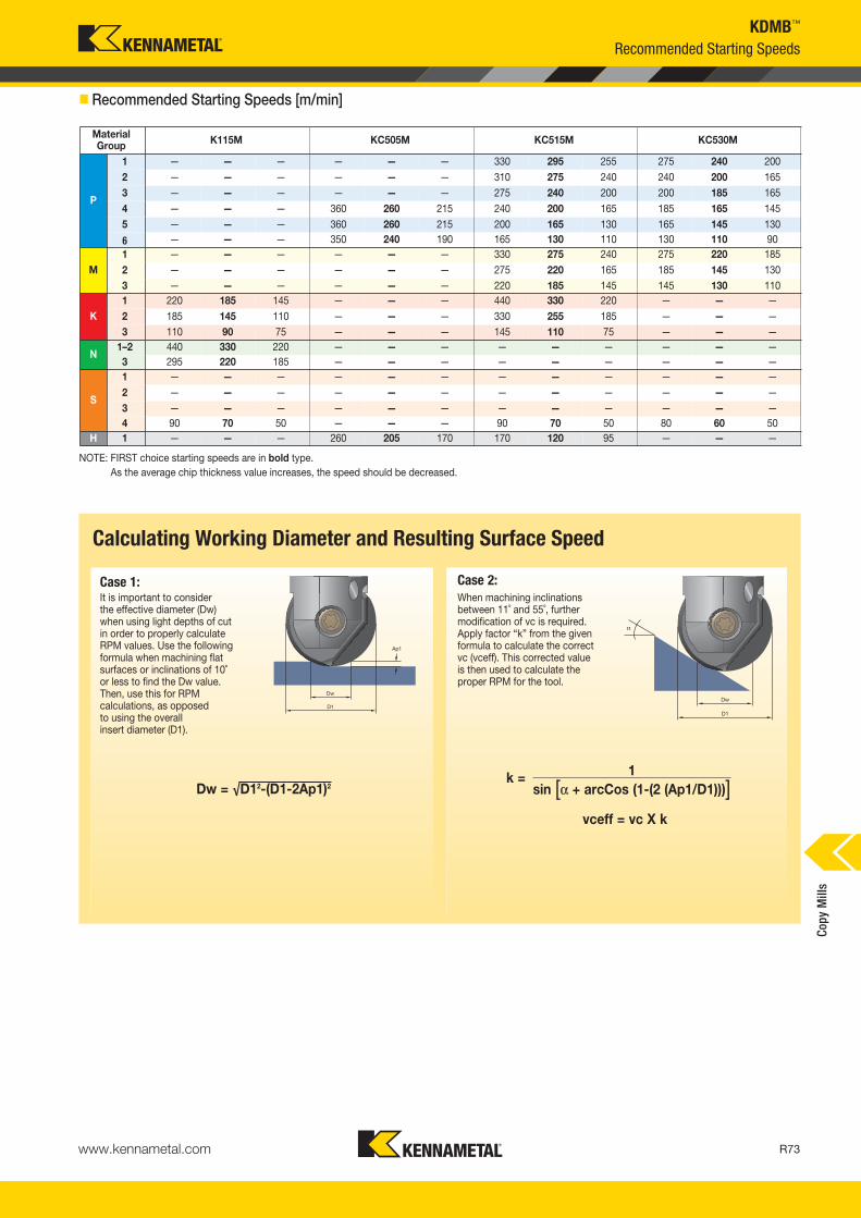
www.kennametal.com R73
KDMB™
NOTE: FIRST choice starting speeds are in bold type.As the average chip thickness value increases, the speed should be decreased.
� Recommended Starting Speeds [m/min]
Recommended Starting Speeds
α
Calculating Working Diameter and Resulting Surface Speed
It is important to consider the effective diameter (Dw) when using light depths of cut in order to properly calculate RPM values. Use the followingformula when machining flatsurfaces or inclinations of 10˚ or less to find the Dw value. Then, use this for RPM calculations, as opposed to using the overall insert diameter (D1).
When machining inclinationsbetween 11˚ and 55˚, furthermodification of vc is required. Apply factor “k” from the givenformula to calculate the correct vc (vceff). This corrected value is then used to calculate the proper RPM for the tool.
Dw = √D12-(D1-2Ap1)2
Case 1: Case 2:
k = 1sin [α + arcCos (1-(2 (Ap1/D1)))]
vceff = vc X k
MaterialGroup K115M KC505M KC515M KC530M
P
1 — — — — — — 330 295 255 275 240 2002 — — — — — — 310 275 240 240 200 1653 — — — — — — 275 240 200 200 185 1654 — — — 360 260 215 240 200 165 185 165 1455 — — — 360 260 215 200 165 130 165 145 130
6 — — — 350 240 190 165 130 110 130 110 90
M1 — — — — — — 330 275 240 275 220 1852 — — — — — — 275 220 165 185 145 1303 — — — — — — 220 185 145 145 130 110
K1 220 185 145 — — — 440 330 220 — — —2 185 145 110 — — — 330 255 185 — — —3 110 90 75 — — — 145 110 75 — — —
N1–2 440 330 220 — — — — — — — — —3 295 220 185 — — — — — — — — —
S
1 — — — — — — — — — — — —2 — — — — — — — — — — — —3 — — — — — — — — — — — —4 90 70 50 — — — 90 70 50 80 60 50
H 1 — — — 260 205 170 170 120 95 — — —
Copy
Mill
s
KM_Master12_R072_R073_METRIC_EN.qxp:Layout 1 3/7/12 9:53 AM Page R73
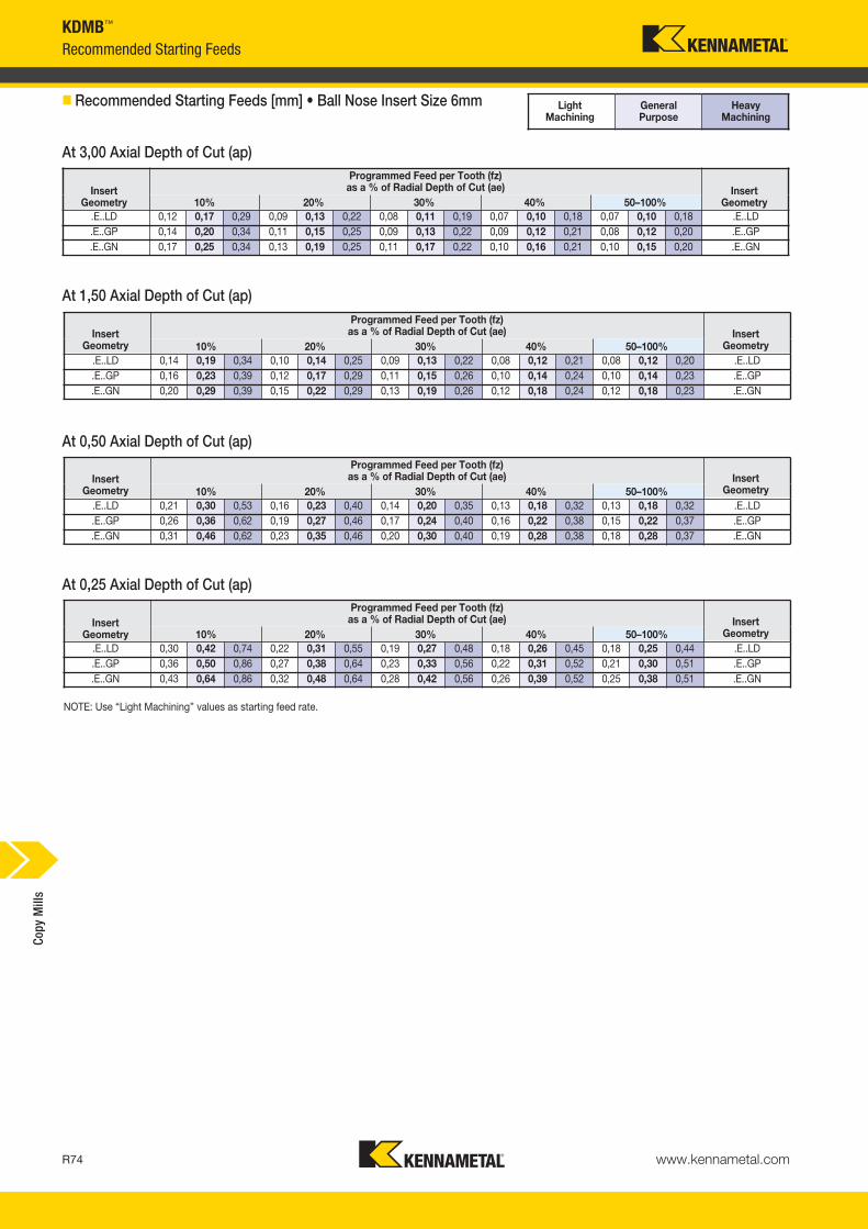
www.kennametal.comR74
InsertGeometry
Programmed Feed per Tooth (fz)as a % of Radial Depth of Cut (ae) Insert
Geometry10% 20% 30% 40% 50–100%.E..LD 0,12 0,17 0,29 0,09 0,13 0,22 0,08 0,11 0,19 0,07 0,10 0,18 0,07 0,10 0,18 .E..LD.E..GP 0,14 0,20 0,34 0,11 0,15 0,25 0,09 0,13 0,22 0,09 0,12 0,21 0,08 0,12 0,20 .E..GP.E..GN 0,17 0,25 0,34 0,13 0,19 0,25 0,11 0,17 0,22 0,10 0,16 0,21 0,10 0,15 0,20 .E..GN
InsertGeometry
Programmed Feed per Tooth (fz)as a % of Radial Depth of Cut (ae) Insert
Geometry10% 20% 30% 40% 50–100%.E..LD 0,14 0,19 0,34 0,10 0,14 0,25 0,09 0,13 0,22 0,08 0,12 0,21 0,08 0,12 0,20 .E..LD.E..GP 0,16 0,23 0,39 0,12 0,17 0,29 0,11 0,15 0,26 0,10 0,14 0,24 0,10 0,14 0,23 .E..GP.E..GN 0,20 0,29 0,39 0,15 0,22 0,29 0,13 0,19 0,26 0,12 0,18 0,24 0,12 0,18 0,23 .E..GN
InsertGeometry
Programmed Feed per Tooth (fz)as a % of Radial Depth of Cut (ae) Insert
Geometry10% 20% 30% 40% 50–100%.E..LD 0,21 0,30 0,53 0,16 0,23 0,40 0,14 0,20 0,35 0,13 0,18 0,32 0,13 0,18 0,32 .E..LD.E..GP 0,26 0,36 0,62 0,19 0,27 0,46 0,17 0,24 0,40 0,16 0,22 0,38 0,15 0,22 0,37 .E..GP.E..GN 0,31 0,46 0,62 0,23 0,35 0,46 0,20 0,30 0,40 0,19 0,28 0,38 0,18 0,28 0,37 .E..GN
InsertGeometry
Programmed Feed per Tooth (fz)as a % of Radial Depth of Cut (ae) Insert
Geometry10% 20% 30% 40% 50–100%.E..LD 0,30 0,42 0,74 0,22 0,31 0,55 0,19 0,27 0,48 0,18 0,26 0,45 0,18 0,25 0,44 .E..LD.E..GP 0,36 0,50 0,86 0,27 0,38 0,64 0,23 0,33 0,56 0,22 0,31 0,52 0,21 0,30 0,51 .E..GP.E..GN 0,43 0,64 0,86 0,32 0,48 0,64 0,28 0,42 0,56 0,26 0,39 0,52 0,25 0,38 0,51 .E..GN
Light Machining
General Purpose
Heavy Machining
KDMB™
Recommended Starting Feeds
� Recommended Starting Feeds [mm] • Ball Nose Insert Size 6mm
At 3,00 Axial Depth of Cut (ap)
At 1,50 Axial Depth of Cut (ap)
At 0,25 Axial Depth of Cut (ap)
NOTE: Use “Light Machining” values as starting feed rate.
At 0,50 Axial Depth of Cut (ap)
Copy
Mill
s
KM_Master12_R074_R075_METRIC_EN.qxp:Layout 1 3/7/12 9:51 AM Page R74

www.kennametal.com R75
KDMB™
Recommended Starting Feeds
InsertGeometry
Programmed Feed per Tooth (fz)as a % of Radial Depth of Cut (ae) Insert
Geometry10% 20% 30% 40% 50–100%.E..LD 0,12 0,17 0,29 0,09 0,13 0,22 0,08 0,11 0,19 0,07 0,10 0,18 0,07 0,10 0,18 .E..LD.E..GP 0,14 0,20 0,35 0,11 0,15 0,26 0,09 0,13 0,23 0,09 0,12 0,21 0,08 0,12 0,21 .E..GP.E..GN 0,17 0,25 0,43 0,13 0,19 0,32 0,11 0,17 0,28 0,10 0,16 0,26 0,10 0,15 0,25 .E..GN
InsertGeometry
Programmed Feed per Tooth (fz)as a % of Radial Depth of Cut (ae) Insert
Geometry10% 20% 30% 40% 50–100%.E..LD 0,15 0,21 0,38 0,11 0,16 0,28 0,10 0,14 0,24 0,09 0,13 0,23 0,09 0,13 0,22 .E..LD.E..GP 0,18 0,26 0,45 0,14 0,19 0,34 0,12 0,17 0,29 0,11 0,16 0,27 0,11 0,15 0,27 .E..GP.E..GN 0,22 0,33 0,55 0,16 0,24 0,41 0,14 0,21 0,36 0,13 0,20 0,33 0,13 0,20 0,33 .E..GN
InsertGeometry
Programmed Feed per Tooth (fz)as a % of Radial Depth of Cut (ae) Insert
Geometry10% 20% 30% 40% 50–100%.E..LD 0,24 0,35 0,61 0,18 0,26 0,45 0,16 0,23 0,39 0,15 0,21 0,37 0,15 0,21 0,36 .E..LD.E..GP 0,29 0,41 0,73 0,22 0,31 0,54 0,19 0,27 0,47 0,18 0,25 0,44 0,18 0,25 0,43 .E..GP.E..GN 0,35 0,53 0,88 0,26 0,39 0,66 0,23 0,34 0,57 0,21 0,32 0,54 0,21 0,31 0,52 .E..GN
InsertGeometry
Programmed Feed per Tooth (fz)as a % of Radial Depth of Cut (ae) Insert
Geometry10% 20% 30% 40% 50–100%.E..LD 0,34 0,48 0,85 0,25 0,36 0,63 0,22 0,31 0,55 0,21 0,29 0,51 0,20 0,29 0,50 .E..LD.E..GP 0,41 0,58 1,02 0,31 0,43 0,76 0,27 0,38 0,66 0,25 0,35 0,62 0,24 0,34 0,60 .E..GP.E..GN 0,49 0,74 1,23 0,37 0,55 0,92 0,32 0,48 0,80 0,30 0,45 0,75 0,29 0,44 0,73 .E..GN
Light Machining
General Purpose
Heavy Machining
� Recommended Starting Feeds [mm] • Ball Nose Insert Size 8mm
At 4,00 Axial Depth of Cut (ap)
At 1,50 Axial Depth of Cut (ap)
At 0,50 Axial Depth of Cut (ap)
At 0,25 Axial Depth of Cut (ap)
NOTE: Use “Light Machining” values as starting feed rate.
Copy
Mill
s
KM_Master12_R074_R075_METRIC_EN.qxp:Layout 1 3/7/12 9:51 AM Page R75

www.kennametal.comR76
InsertGeometry
Programmed Feed per Tooth (fz)as a % of Radial Depth of Cut (ae) Insert
Geometry10% 20% 30% 40% 50–100%.E..LD 0,12 0,17 0,29 0,09 0,13 0,22 0,08 0,11 0,19 0,07 0,10 0,18 0,07 0,10 0,18 .E..LD.E..GP 0,14 0,20 0,35 0,11 0,15 0,26 0,09 0,13 0,23 0,09 0,12 0,21 0,08 0,12 0,21 .E..GP.E..GN 0,17 0,27 0,47 0,13 0,20 0,35 0,11 0,17 0,31 0,10 0,16 0,29 0,10 0,16 0,28 .E..GN
InsertGeometry
Programmed Feed per Tooth (fz)as a % of Radial Depth of Cut (ae) Insert
Geometry10% 20% 30% 40% 50–100%.E..LD 0,15 0,21 0,37 0,11 0,16 0,27 0,10 0,14 0,24 0,09 0,13 0,22 0,09 0,13 0,22 .E..LD.E..GP 0,18 0,25 0,44 0,13 0,19 0,33 0,12 0,16 0,29 0,11 0,15 0,27 0,11 0,15 0,26 .E..GP.E..GN 0,21 0,33 0,59 0,16 0,25 0,44 0,14 0,22 0,38 0,13 0,20 0,36 0,13 0,20 0,35 .E..GN
InsertGeometry
Programmed Feed per Tooth (fz)as a % of Radial Depth of Cut (ae) Insert
Geometry10% 20% 30% 40% 50–100%.E..LD 0,20 0,28 0,49 0,15 0,21 0,37 0,13 0,18 0,32 0,12 0,17 0,30 0,12 0,17 0,29 .E..LD.E..GP 0,24 0,33 0,59 0,18 0,25 0,44 0,15 0,22 0,38 0,14 0,20 0,36 0,14 0,20 0,35 .E..GP.E..GN 0,28 0,45 0,78 0,21 0,33 0,58 0,18 0,29 0,51 0,17 0,27 0,48 0,17 0,27 0,47 .E..GN
InsertGeometry
Programmed Feed per Tooth (fz)as a % of Radial Depth of Cut (ae) Insert
Geometry10% 20% 30% 40% 50–100%.E..LD 0,27 0,38 0,67 0,20 0,29 0,50 0,18 0,25 0,44 0,17 0,23 0,41 0,16 0,23 0,40 .E..LD.E..GP 0,33 0,46 0,81 0,24 0,34 0,60 0,21 0,30 0,53 0,20 0,28 0,49 0,19 0,28 0,48 .E..GP.E..GN 0,39 0,62 1,08 0,29 0,46 0,81 0,25 0,40 0,70 0,24 0,37 0,66 0,23 0,37 0,64 .E..GN
Light Machining
General Purpose
Heavy Machining
KDMB™
Recommended Starting Feeds
� Recommended Starting Feeds [mm] • Ball Nose Insert Size 10mm
NOTE: Use "Light Machining" values as starting feed rate.
At 2,00 Axial Depth of Cut (ap)
At 1,00 Axial Depth of Cut (ap)
At 0,50 Axial Depth of Cut (ap)
At 5,00 Axial Depth of Cut (ap)
Copy
Mill
s
KM_Master12_R076_R077_METRIC_EN.qxp:Layout 1 3/7/12 9:50 AM Page R76

www.kennametal.com R77
KDMB™
Recommended Starting Feeds
InsertGeometry
Programmed Feed per Tooth (fz)as a % of Radial Depth of Cut (ae) Insert
Geometry10% 20% 30% 40% 50–100%.E..LD 0,12 0,17 0,29 0,09 0,13 0,22 0,08 0,11 0,19 0,07 0,10 0,18 0,07 0,10 0,18 .E..LD.E..GP 0,14 0,20 0,35 0,11 0,15 0,26 0,09 0,13 0,23 0,09 0,12 0,21 0,08 0,12 0,21 .E..GP.E..GN 0,17 0,27 0,47 0,13 0,20 0,35 0,11 0,17 0,31 0,10 0,16 0,29 0,10 0,16 0,28 .E..GN.E..HC 0,17 0,33 0,59 0,13 0,25 0,44 0,11 0,22 0,38 0,10 0,20 0,36 0,10 0,20 0,35 .E..HC
InsertGeometry
Programmed Feed per Tooth (fz)as a % of Radial Depth of Cut (ae) Insert
Geometry10% 20% 30% 40% 50–100%.E..LD 0,16 0,22 0,39 0,12 0,17 0,29 0,10 0,15 0,26 0,10 0,14 0,24 0,09 0,13 0,23 .E..LD.E..GP 0,19 0,27 0,47 0,14 0,20 0,35 0,12 0,18 0,31 0,12 0,16 0,29 0,11 0,16 0,28 .E..GP.E..GN 0,23 0,36 0,63 0,17 0,27 0,47 0,15 0,23 0,41 0,14 0,22 0,38 0,14 0,21 0,38 .E..GN.E..HC 0,23 0,45 0,79 0,17 0,34 0,59 0,15 0,29 0,51 0,14 0,27 0,48 0,14 0,27 0,47 .E..HC
InsertGeometry
Programmed Feed per Tooth (fz)as a % of Radial Depth of Cut (ae) Insert
Geometry10% 20% 30% 40% 50–100%.E..LD 0,21 0,30 0,53 0,16 0,23 0,40 0,14 0,20 0,35 0,13 0,18 0,32 0,13 0,18 0,32 .E..LD.E..GP 0,26 0,36 0,64 0,19 0,27 0,48 0,17 0,24 0,41 0,16 0,22 0,39 0,15 0,22 0,38 .E..GP.E..GN 0,31 0,48 0,85 0,23 0,36 0,64 0,20 0,32 0,55 0,19 0,30 0,52 0,18 0,29 0,51 .E..GN.E..HC 0,31 0,61 1,07 0,23 0,45 0,79 0,20 0,40 0,69 0,19 0,37 0,65 0,18 0,36 0,63 .E..HC
InsertGeometry
Programmed Feed per Tooth (fz)as a % of Radial Depth of Cut (ae) Insert
Geometry10% 20% 30% 40% 50–100%.E..LD 0,30 0,42 0,74 0,22 0,31 0,55 0,19 0,27 0,48 0,18 0,26 0,45 0,18 0,25 0,44 .E..LD.E..GP 0,36 0,50 0,88 0,27 0,38 0,66 0,23 0,33 0,57 0,22 0,31 0,54 0,21 0,30 0,53 .E..GP.E..GN 0,43 0,67 1,18 0,32 0,50 0,88 0,28 0,44 0,77 0,26 0,41 0,72 0,25 0,40 0,70 .E..GN.E..HC 0,43 0,84 1,48 0,32 0,63 1,10 0,28 0,55 0,96 0,26 0,51 0,89 0,25 0,50 0,88 .E..HC
Light Machining
General Purpose
Heavy Machining
� Recommended Starting Feeds [mm] • Ball Nose Insert Size 12mm
At 6,00 Axial Depth of Cut (ap)
NOTES: Use "Light Machining" values as starting feed rate.
At 2,00 Axial Depth of Cut (ap)
At 0,50 Axial Depth of Cut (ap)
At 1,00 Axial Depth of Cut (ap)
Copy
Mill
s
KM_Master12_R076_R077_METRIC_EN.qxp:Layout 1 3/7/12 9:50 AM Page R77

www.kennametal.comR78
KDMB™
Recommended Starting Feeds
InsertGeometry
Programmed Feed per Tooth (fz)as a % of Radial Depth of Cut (ae) Insert
Geometry10% 20% 30% 40% 50–100%.E..LD 0,12 0,17 0,29 0,09 0,13 0,22 0,08 0,11 0,19 0,07 0,10 0,18 0,07 0,10 0,18 .E..LD.E..GP 0,14 0,20 0,35 0,11 0,15 0,26 0,09 0,13 0,23 0,09 0,12 0,21 0,08 0,12 0,21 .E..GP.E..GN 0,17 0,27 0,47 0,13 0,20 0,35 0,11 0,17 0,31 0,10 0,16 0,29 0,10 0,16 0,28 .E..GN.E..HC 0,17 0,33 0,59 0,13 0,25 0,44 0,11 0,22 0,38 0,10 0,20 0,36 0,10 0,20 0,35 .E..HC
InsertGeometry
Programmed Feed per Tooth (fz)as a % of Radial Depth of Cut (ae) Insert
Geometry10% 20% 30% 40% 50–100%.E..LD 0,15 0,21 0,38 0,11 0,16 0,28 0,10 0,14 0,24 0,09 0,13 0,23 0,09 0,13 0,22 .E..LD.E..GP 0,18 0,26 0,45 0,14 0,19 0,34 0,12 0,17 0,29 0,11 0,16 0,27 0,11 0,15 0,27 .E..GP.E..GN 0,22 0,34 0,60 0,16 0,26 0,45 0,14 0,22 0,39 0,13 0,21 0,37 0,13 0,2 0,36 .E..GN.E..HC 0,22 0,43 0,75 0,16 0,32 0,56 0,14 0,28 0,49 0,13 0,26 0,46 0,13 0,26 0,45 .E..HC
InsertGeometry
Programmed Feed per Tooth (fz)as a % of Radial Depth of Cut (ae) Insert
Geometry10% 20% 30% 40% 50–100%.E..LD 0,20 0,29 0,50 0,15 0,21 0,38 0,13 0,19 0,33 0,12 0,18 0,31 0,12 0,17 0,30 .E..LD.E..GP 0,24 0,34 0,60 0,18 0,26 0,45 0,16 0,22 0,39 0,15 0,21 0,37 0,15 0,21 0,36 .E..GP.E..GN 0,29 0,46 0,81 0,22 0,34 0,60 0,19 0,30 0,52 0,18 0,28 0,49 0,17 0,27 0,48 .E..GN.E..HC 0,29 0,58 1,01 0,22 0,43 0,75 0,19 0,37 0,66 0,18 0,35 0,61 0,17 0,34 0,60 .E..HC
InsertGeometry
Programmed Feed per Tooth (fz)as a % of Radial Depth of Cut (ae) Insert
Geometry10% 20% 30% 40% 50–100%.E..LD 0,28 0,40 0,7 0,21 0,30 0,52 0,18 0,26 0,45 0,17 0,24 0,42 0,17 0,24 0,41 .E..LD.E..GP 0,34 0,48 0,84 0,25 0,36 0,62 0,22 0,31 0,54 0,20 0,29 0,51 0,20 0,28 0,50 .E..GP.E..GN 0,40 0,64 1,12 0,30 0,47 0,83 0,26 0,41 0,72 0,25 0,39 0,68 0,24 0,38 0,66 .E..GN.E..HC 0,40 0,80 1,40 0,30 0,59 1,04 0,26 0,52 0,90 0,25 0,48 0,85 0,24 0,47 0,83 .E..HC
Light Machining
General Purpose
Heavy Machining
� Recommended Starting Feeds [mm] • Ball Nose Insert Size 16mm
At 1,50 Axial Depth of Cut (ap)
At 0,75 Axial Depth of Cut (ap)
At 3,00 Axial Depth of Cut (ap)
NOTE: Use "Light Machining" values as starting feed rate.
At 8,00 Axial Depth of Cut (ap)
Copy
Mill
s
KM_Master12_R078_R079_METRIC_EN.qxp:Layout 1 3/7/12 9:50 AM Page R78

www.kennametal.com R79
KDMB™
Recommended Starting Feeds
InsertGeometry
Programmed Feed per Tooth (fz)as a % of Radial Depth of Cut (ae) Insert
Geometry10% 20% 30% 40% 50–100%.E..LD 0,12 0,17 0,33 0,09 0,13 0,25 0,08 0,11 0,22 0,07 0,10 0,20 0,07 0,10 0,20 .E..LD.E..GP 0,14 0,20 0,40 0,11 0,15 0,30 0,09 0,13 0,26 0,09 0,12 0,24 0,08 0,12 0,24 .E..GP.E..GN 0,17 0,27 0,54 0,13 0,20 0,40 0,11 0,17 0,35 0,10 0,16 0,33 0,10 0,16 0,32 .E..GN.E..HC 0,17 0,33 0,67 0,13 0,25 0,50 0,11 0,22 0,44 0,10 0,20 0,41 0,10 0,20 0,40 .E..HC
InsertGeometry
Programmed Feed per Tooth (fz)as a % of Radial Depth of Cut (ae) Insert
Geometry10% 20% 30% 40% 50–100%.E..LD 0,17 0,23 0,47 0,12 0,18 0,35 0,11 0,15 0,31 0,10 0,14 0,29 0,10 0,14 0,28 .E..LD.E..GP 0,20 0,28 0,56 0,15 0,21 0,42 0,13 0,18 0,37 0,12 0,17 0,34 0,12 0,17 0,34 .E..GP.E..GN 0,24 0,37 0,75 0,18 0,28 0,56 0,16 0,24 0,49 0,15 0,23 0,46 0,14 0,22 0,45 .E..GN.E..HC 0,24 0,47 0,94 0,18 0,35 0,70 0,16 0,31 0,61 0,15 0,29 0,57 0,14 0,28 0,56 .E..HC
InsertGeometry
Programmed Feed per Tooth (fz)as a % of Radial Depth of Cut (ae) Insert
Geometry10% 20% 30% 40% 50–100%.E..LD 0,22 0,32 0,64 0,17 0,24 0,48 0,15 0,21 0,41 0,14 0,19 0,39 0,13 0,19 0,38 .E..LD.E..GP 0,27 0,38 0,77 0,20 0,29 0,57 0,18 0,25 0,50 0,16 0,23 0,47 0,16 0,23 0,46 .E..GP.E..GN 0,32 0,51 1,02 0,24 0,38 0,76 0,21 0,33 0,66 0,20 0,31 0,62 0,19 0,30 0,61 .E..GN.E..HC 0,32 0,64 1,28 0,24 0,48 0,95 0,21 0,41 0,83 0,20 0,39 0,78 0,19 0,38 0,76 .E..HC
InsertGeometry
Programmed Feed per Tooth (fz)as a % of Radial Depth of Cut (ae) Insert
Geometry10% 20% 30% 40% 50–100%.E..LD 0,31 0,44 0,89 0,23 0,33 0,66 0,20 0,29 0,57 0,19 0,27 0,54 0,19 0,26 0,53 .E..LD.E..GP 0,37 0,53 1,06 0,28 0,40 0,79 0,24 0,34 0,69 0,23 0,32 0,64 0,22 0,32 0,63 .E..GP.E..GN 0,45 0,71 1,43 0,33 0,53 1,06 0,29 0,46 0,92 0,27 0,43 0,86 0,27 0,42 0,84 .E..GN.E..HC 0,45 0,89 1,79 0,33 0,66 1,32 0,29 0,57 1,15 0,27 0,54 1,07 0,27 0,53 1,05 .E..HC
Light Machining
General Purpose
Heavy Machining
� Recommended Starting Feeds [mm] • Ball Nose Insert Size 20mm
At 10,00 Axial Depth of Cut (ap)
NOTE: Use “Light Machining” values as starting feed rate.
At 3,00 Axial Depth of Cut (ap)
At 1,50 Axial Depth of Cut (ap)
At 0,75 Axial Depth of Cut (ap)
Copy
Mill
s
KM_Master12_R078_R079_METRIC_EN.qxp:Layout 1 3/7/12 9:50 AM Page R79

www.kennametal.comR80
KDMB™
Recommended Starting Feeds
InsertGeometry
Programmed Feed per Tooth (fz)as a % of Radial Depth of Cut (ae) Insert
Geometry10% 20% 30% 40% 50–100%.E..LD 0,12 0,17 0,29 0,09 0,13 0,22 0,08 0,11 0,19 0,07 0,10 0,18 0,07 0,10 0,18 .E..LD.E..GP 0,14 0,20 0,35 0,11 0,15 0,26 0,09 0,13 0,23 0,09 0,12 0,21 0,08 0,12 0,21 .E..GP.E..GN 0,17 0,27 0,47 0,13 0,20 0,35 0,11 0,17 0,31 0,10 0,16 0,29 0,10 0,16 0,28 .E..GN.E..HC 0,17 0,33 0,59 0,13 0,25 0,44 0,11 0,22 0,38 0,10 0,20 0,36 0,10 0,20 0,35 .E..HC
InsertGeometry
Programmed Feed per Tooth (fz)as a % of Radial Depth of Cut (ae) Insert
Geometry10% 20% 30% 40% 50–100%.E..LD 0,15 0,21 0,37 0,11 0,16 0,27 0,10 0,14 0,24 0,09 0,13 0,22 0,09 0,13 0,22 .E..LD.E..GP 0,18 0,25 0,44 0,13 0,19 0,33 0,12 0,16 0,29 0,11 0,15 0,27 0,11 0,15 0,26 .E..GP.E..GN 0,21 0,33 0,59 0,16 0,25 0,44 0,14 0,22 0,38 0,13 0,20 0,36 0,13 0,20 0,35 .E..GN.E..HC 0,21 0,42 0,73 0,16 0,31 0,55 0,14 0,27 0,48 0,13 0,26 0,45 0,13 0,25 0,44 .E..HC
InsertGeometry
Programmed Feed per Tooth (fz)as a % of Radial Depth of Cut (ae) Insert
Geometry10% 20% 30% 40% 50–100%.E..LD 0,22 0,31 0,54 0,16 0,23 0,40 0,14 0,20 0,35 0,13 0,19 0,33 0,13 0,18 0,32 .E..LD.E..GP 0,26 0,37 0,65 0,20 0,28 0,48 0,17 0,24 0,42 0,16 0,23 0,40 0,16 0,22 0,39 .E..GP.E..GN 0,31 0,49 0,87 0,23 0,37 0,65 0,20 0,32 0,56 0,19 0,30 0,53 0,19 0,29 0,52 .E..GN.E..HC 0,31 0,62 1,09 0,23 0,46 0,81 0,20 0,40 0,70 0,19 0,38 0,66 0,19 0,37 0,65 .E..HC
InsertGeometry
Programmed Feed per Tooth (fz)as a % of Radial Depth of Cut (ae) Insert
Geometry10% 20% 30% 40% 50–100%.E..LD 0,30 0,43 0,75 0,23 0,32 0,56 0,20 0,28 0,49 0,18 0,26 0,46 0,18 0,26 0,45 .E..LD.E..GP 0,36 0,51 0,90 0,27 0,38 0,67 0,24 0,33 0,59 0,22 0,31 0,55 0,22 0,31 0,54 .E..GP.E..GN 0,43 0,69 1,21 0,32 0,51 0,90 0,28 0,45 0,78 0,26 0,42 0,73 0,26 0,41 0,71 .E..GN.E..HC 0,43 0,86 1,51 0,32 0,64 1,12 0,28 0,56 0,98 0,26 0,52 0,91 0,26 0,51 0,89 .E..HC
Light Machining
General Purpose
Heavy Machining
� Recommended Starting Feeds [mm] • Ball Nose Insert Size 25mm
At 12,50 Axial Depth of Cut (ap)
At 1,00 Axial Depth of Cut (ap)
NOTE: Use “Light Machining” values as starting feed rate.
At 5,00 Axial Depth of Cut (ap)
At 2,00 Axial Depth of Cut (ap)
Copy
Mill
s
KM_Master12_R080_R081_METRIC_EN.qxp:Layout 1 3/7/12 9:49 AM Page R80
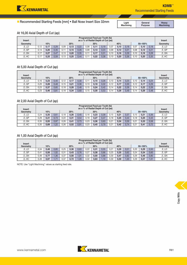
www.kennametal.com R81
KDMB™
Recommended Starting Feeds
InsertProgrammed Feed per Tooth (fz)
as a % of Radial Depth of Cut (ae) InsertGeometry 10% 20% 30% 40% 50–100% Geometry
.E..LD 0,12 0,17 0,29 0,09 0,13 0,22 0,08 0,11 0,19 0,07 0,10 0,18 0,07 0,10 0,18 .E..LD.E..GP 0,14 0,20 0,35 0,11 0,15 0,26 0,09 0,13 0,23 0,09 0,12 0,21 0,08 0,12 0,21 .E..GP.E..GN 0,17 0,27 0,47 0,13 0,20 0,35 0,11 0,17 0,31 0,10 0,16 0,29 0,10 0,16 0,28 .E..GN.E..HC 0,17 0,33 0,59 0,13 0,25 0,44 0,11 0,22 0,38 0,10 0,20 0,36 0,10 0,20 0,35 .E..HC
Programmed Feed per Tooth (fz)as a % of Radial Depth of Cut (ae)Insert
Geometry 10% 20% 30% 40% 50–100%Insert
Geometry.E..LD 0,16 0,23 0,40 0,12 0,17 0,30 0,11 0,15 0,26 0,10 0,14 0,25 0,10 0,14 0,24 .E..LD.E..GP 0,20 0,28 0,48 0,15 0,21 0,36 0,13 0,18 0,32 0,12 0,17 0,30 0,12 0,17 0,29 .E..GP.E..GN 0,23 0,37 0,65 0,18 0,28 0,48 0,15 0,24 0,42 0,14 0,22 0,39 0,14 0,22 0,39 .E..GN.E..HC 0,23 0,46 0,81 0,18 0,34 0,60 0,15 0,30 0,53 0,14 0,28 0,49 0,14 0,28 0,48 .E..HC
Programmed Feed per Tooth (fz)as a % of Radial Depth of Cut (ae)Insert
Geometry 10% 20% 30% 40% 50–100%Insert
Geometry.E..LD 0,24 0,35 0,61 0,18 0,26 0,45 0,16 0,23 0,39 0,15 0,21 0,37 0,15 0,21 0,36 .E..LD.E..GP 0,29 0,41 0,73 0,22 0,31 0,54 0,19 0,27 0,47 0,18 0,25 0,44 0,18 0,25 0,43 .E..GP.E..GN 0,35 0,55 0,97 0,26 0,41 0,73 0,23 0,36 0,63 0,21 0,34 0,59 0,21 0,33 0,58 .E..GN.E..HC 0,35 0,69 1,22 0,26 0,52 0,91 0,23 0,45 0,79 0,21 0,42 0,74 0,21 0,41 0,72 .E..HC
Programmed Feed per Tooth (fz)as a % of Radial Depth of Cut (ae)Insert
Geometry 10% 20% 30% 40% 50–100%Insert
Geometry.E..LD 0,34 0,48 0,85 0,25 0,36 0,63 0,22 0,31 0,55 0,21 0,29 0,51 0,20 0,29 0,50 .E..LD.E..GP 0,41 0,58 1,02 0,31 0,43 0,76 0,27 0,38 0,66 0,25 0,35 0,62 0,24 0,34 0,60 .E..GP.E..GN 0,49 0,77 1,36 0,37 0,58 1,01 0,32 0,50 0,88 0,30 0,47 0,82 0,29 0,46 0,80 .E..GN.E..HC 0,49 0,97 1,71 0,37 0,72 1,26 0,32 0,63 1,10 0,30 0,59 1,03 0,29 0,57 1,01 .E..HC
Light Machining
General Purpose
Heavy Machining
� Recommended Starting Feeds [mm] • Ball Nose Insert Size 32mm
At 16,00 Axial Depth of Cut (ap)
NOTE: Use “Light Machining” values as starting feed rate.
At 1,00 Axial Depth of Cut (ap)
At 2,00 Axial Depth of Cut (ap)
At 5,00 Axial Depth of Cut (ap)
Copy
Mill
s
KM_Master12_R080_R081_METRIC_EN.qxp:Layout 1 3/7/12 9:49 AM Page R81
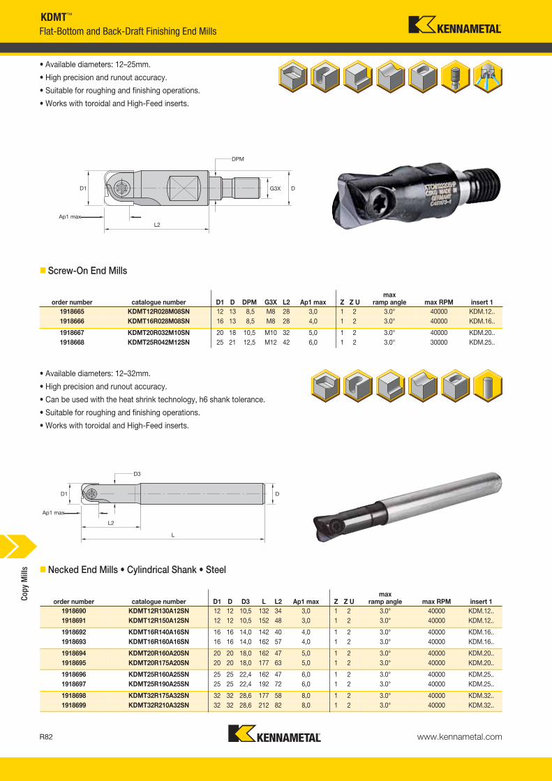
www.kennametal.comR82
KDMT™
Flat-Bottom and Back-Draft Finishing End Mills
• Available diameters: 12–25mm.
• High precision and runout accuracy.
• Suitable for roughing and finishing operations.
• Works with toroidal and High-Feed inserts.
� Screw-On End Mills
order number catalogue number D1 D D3 L L2 Ap1 max Z Z Umax
ramp angle max RPM insert 11918690 KDMT12R130A12SN 12 12 10,5 132 34 3,0 1 2 3.0° 40000 KDM.12..1918691 KDMT12R150A12SN 12 12 10,5 152 48 3,0 1 2 3.0° 40000 KDM.12..
1918692 KDMT16R140A16SN 16 16 14,0 142 40 4,0 1 2 3.0° 40000 KDM.16..1918693 KDMT16R160A16SN 16 16 14,0 162 57 4,0 1 2 3.0° 40000 KDM.16..
1918694 KDMT20R160A20SN 20 20 18,0 162 47 5,0 1 2 3.0° 40000 KDM.20..1918695 KDMT20R175A20SN 20 20 18,0 177 63 5,0 1 2 3.0° 40000 KDM.20..
1918696 KDMT25R160A25SN 25 25 22,4 162 47 6,0 1 2 3.0° 40000 KDM.25..1918697 KDMT25R190A25SN 25 25 22,4 192 72 6,0 1 2 3.0° 40000 KDM.25..
1918698 KDMT32R175A32SN 32 32 28,6 177 58 8,0 1 2 3.0° 40000 KDM.32..1918699 KDMT32R210A32SN 32 32 28,6 212 82 8,0 1 2 3.0° 40000 KDM.32..
• Available diameters: 12–32mm.
• High precision and runout accuracy.
• Can be used with the heat shrink technology, h6 shank tolerance.
• Suitable for roughing and finishing operations.
• Works with toroidal and High-Feed inserts.
� Necked End Mills • Cylindrical Shank • Steel
Copy
Mill
s
order number catalogue number D1 D DPM G3X L2 Ap1 max Z Z Umax
ramp angle max RPM insert 11918665 KDMT12R028M08SN 12 13 8,5 M8 28 3,0 1 2 3.0° 40000 KDM.12..1918666 KDMT16R028M08SN 16 13 8,5 M8 28 4,0 1 2 3.0° 40000 KDM.16..
1918667 KDMT20R032M10SN 20 18 10,5 M10 32 5,0 1 2 3.0° 40000 KDM.20..1918668 KDMT25R042M12SN 25 21 12,5 M12 42 6,0 1 2 3.0° 30000 KDM.25..
KM_Master12_R082_R083_METRIC_EN.qxp:Layout 1 3/7/12 9:49 AM Page R82

www.kennametal.com R83
order number catalogue number D1 D D3 L L2 Ap1 max Z Z Umax
ramp angle max RPM insert 13964255 KDMT10R120A10HNC 10 10 9 122 37 2,5 1 2 3.0° 40000 KDM.10..3964256 KDMT10R150A10HNC 10 10 9 152 52 2,5 1 2 3.0° 40000 KDM.10..
2877384 KDMT12R120A12HNC 12 12 11 122 37 3,0 1 2 3.0° 40000 KDM.12..2877385 KDMT12R160A12HNC 12 12 11 162 52 3,0 1 2 3.0° 40000 KDM.12..
2877386 KDMT16R140A16HNC 16 16 14 142 42 4,0 1 2 3.0° 40000 KDM.16..2877387 KDMT16R175A16HNC 16 16 14 177 57 4,0 1 2 3.0° 40000 KDM.16..
2877388 KDMT20R140A20HNC 20 20 18 142 52 5,0 1 2 3.0° 40000 KDM.20..2877389 KDMT20R190A20HNC 20 20 18 192 77 5,0 1 2 3.0° 40000 KDM.20..
2877390 KDMT25R160A25HNC 25 25 22 162 62 6,0 1 2 3.0° 30000 KDM.25..2877391 KDMT25R210A25HNC 25 25 22 212 92 6,0 1 2 3.0° 30000 KDM.25..
2877392 KDMT32R190A32HNC 32 32 29 192 67 8,0 1 2 3.0° 30000 KDM.32..2877453 KDMT32R240A32HNC 32 32 29 242 107 8,0 1 2 3.0° 30000 KDM.32..
D1insert screw Nm
Torx wrench
10 193.394 3,0 KT1512 193.393 4,0 KT20
16 193.392 5,0 KT2020 193.391 6,0 KT20
25 193.390 6,5 KT3032 193.389 6,5 KT30
KDMT™
Flat-Bottom and Back-Draft Finishing End Mills
• Available diameters: 10–32mm.
• High precision and runout accuracy.
• Can be used with the heat shrink technology, h6 shank tolerance.
• Suitable for roughing and finishing operations.
• Works with toroidal and High-Feed inserts.
� Necked End Mills • Carbide Shank with Through Coolant
� Spare Parts
Copy
Mill
s
KM_Master12_R082_R083_METRIC_EN.qxp:Layout 1 3/7/12 9:49 AM Page R83

www.kennametal.comR84
KDMS™ • KDMT™
Inserts
� Insert Selection Guide
MaterialGroup
Light Machining General Purpose Heavy Machining
Geometry Grade Geometry Grade Geometry GradeP1–P2 .E..GC KC515M .E..GC KC515M .E..GN KC515M
P3–P4 .E..HC KC505M .E..GN KC515M .E..GN KC515M
P5–P6 .E..HC KC505M .E..GN KC515M .E..GN KC515M
M1–M2 — — .E..GC KC515M — —
M3 — — .E..GC KC515M — —
K1–K2 .E..GN KC515M .E..GN KC515M .E..GN KC515M
K3 .E..GN KC515M .E..GN KC515M .E..GN KC515M
N1–N2 — — — — — —
N3 — — — — — —
S1–S2 — — — — — —
S3 — — — — — —
S4 — — .E..GC KC515M — —
H1 .E..HC KC505M .E..HC KC505M .E..GN KC515M
catalogue number LI W S RR hm KC
515M
KDMS0806ERGN 9,50 8,00 2,00 0,6 0,08 �
KDMS1008ERGN 11,50 10,00 2,50 0,8 0,08 �
KDMS1210ERGN 14,00 12,00 2,50 1,0 0,08 �
KDMS1613ERGN 16,00 16,00 3,00 1,3 0,08 �
KDMS2016ERGN 18,00 20,00 3,00 1,6 0,08 �
KDMS2520ERGN 23,50 25,00 4,00 2,0 0,08 �
KDMS3220ERGN 28,00 32,00 5,00 2,0 0,08 �
catalogue number LI W S RR hm KC
515M
KDMT0605ERGC 8,00 6,00 1,60 0,5 0,05 �
KDMT0810ERGC 9,50 8,00 2,00 1,0 0,05 �
KDMT1010ERGC 11,50 10,00 2,50 1,0 0,05 �
KDMT1210ERGC 14,00 12,00 2,50 1,0 0,08 �
KDMT1610ERGC 16,00 16,00 3,00 1,0 0,08 �
KDMT2010ERGC 18,00 20,00 3,00 1,0 0,08 �
KDMT2510ERGC 23,50 25,00 4,00 1,0 0,08 �
Indexable Inserts • KDMS... • KDMT...
KDMS-GN KDMT-GC
� KDMS-GN • Precision Insert • 90° Capabilities
� KDMT-GC • High-Tolerance Helical Geometry • Finishing Lower Cutting Forces
NOTE: Ap1 max is equal to RR.Insert diameter 6mm and 8mm use KDMB holder type. See pages R65–R68.
P �
M �
K �
NSH �
� first choice� alternate choice
NOTE: Ap1 max is equal to LI.Insert diameter 6mm and 8mm use KDMB holder type. See pages R65–R68.
Copy
Mill
s
KM_Master12_R084_R085_METRIC_EN.qxp:Layout 1 3/7/12 9:53 AM Page R84

www.kennametal.com R85
KDMT-GN KDMT-HC KDMT-HF
KDMS™ • KDMT™
Indexable Inserts • KDMS... • KDMT...
P � �
M � �
K � �
NS �
H � �
� first choice� alternate choice
catalogue number LI W S RR hm K11
5MK
C50
5MK
C51
5M
KDMT0806ERGN 9,50 8,00 2,00 0,6 0,07 �
KDMT1008ERGN 11,50 10,00 2,50 0,8 0,07 �
KDMT1210ERGN 14,00 12,00 2,50 1,0 0,08 �
KDMT1220ERGN 14,00 12,00 2,50 2,0 0,08 �
KDMT1610ERGN 16,00 16,00 3,00 1,0 0,08 �
KDMT1630ERGN 16,00 16,00 3,00 3,0 0,08 �
KDMT2010ERGN 18,00 20,00 3,00 1,0 0,08 �
KDMT2040ERGN 18,00 20,00 3,00 4,0 0,08 �
KDMT2510ERGN 23,50 25,00 4,00 1,0 0,08 �
catalogue number LI W S RR hm K11
5MK
C50
5MK
C51
5M
KDMT1010ERHC 11,50 10,00 2,50 1,0 0,10 �
KDMT1210ERHC 14,00 12,00 2,50 1,0 0,10 �
KDMT1610ERHC 16,00 16,00 3,00 1,0 0,10 �
KDMT2010ERHC 18,00 20,00 3,00 1,0 0,10 �
� KDMT-GN • High-Precision Insert • Semi-Finishing and Finishing
NOTE: Ap1 max is equal to RR.Insert diameter 6mm and 8mm use KDMB holder type. See pages R65–R68.
� KDMT-HC • New Geometry for Semi-Finishing and Finishing with Coolant and Air Flow Grooves
NOTE: Ap1 max is equal to RR.Insert diameter 6mm and 8mm use KDMB holder type. See pages R65–R68.
� KDMT-HF • Geometry Developed • High-Feed Machining up to 55 HRC
catalogue number LI W S RT hm K11
5MK
C50
5MK
C51
5M
KDMT0604SRHF 8,00 6,00 1,60 0,8 0,08 �
KDMT0806SRHF 9,50 8,00 2,00 1,0 0,08 �
KDMT1008SRHF 11,50 10,00 2,50 1,0 0,08 � �
KDMT1210SRHF 14,00 12,00 2,50 1,0 0,08 � �
KDMT1615SRHF 16,00 16,00 3,00 1,5 0,08 � �
KDMT2020SRHF 18,00 20,00 3,00 2,0 0,08 � �
NOTE: RT= Programming RadiusInsert diameter 6mm and 8mm use KDMB holder type. See pages R65–R68.
Copy
Mill
s
KM_Master12_R084_R085_METRIC_EN.qxp:Layout 1 3/7/12 9:53 AM Page R85

www.kennametal.comR86
NOTE: FIRST choice starting speeds are in bold type.As the average chip thickness increases, the speed should be decreased.
Light Machining
General Purpose
Heavy Machining
KDMS™ • KDMT™
NOTE: Use “Light Machining” values as starting feed rate.
MaterialGroup K115M KC505M KC515M
P
1 — — — — — — 330 295 255
2 — — — — — — 310 275 2403 — — — — — — 275 240 2004 — — — 360 260 215 240 200 1655 — — — 360 260 215 200 165 1306 — — — 350 240 190 165 130 110
M1 — — — — — — 330 275 2402 — — — — — — 275 220 1653 — — — — — — 220 185 145
K1 220 185 145 — — — 440 330 2202 185 145 110 — — — 330 255 1853 110 90 75 — — — 145 110 75
N1–2 440 330 220 — — — — — — 3 295 220 185 — — — — — —
S
1 — — — — — — — — — 2 — — — — — — — — — 3 — — — — — — — — — 4 90 70 50 — — — — — —
H 1 — — — 260 205 170 170 120 95
� Recommended Starting Speeds [m/min]
� Recommended Starting Feeds [mm]
InsertGeometry
Programmed Feed per Tooth (fz)as a % of Radial Depth of Cut (ae) Insert
Geometry10% 20% 30% 40% 50–100%.E..GC 0,12 0,25 0,34 0,09 0,19 0,25 0,08 0,17 0,22 0,07 0,16 0,21 0,07 0,15 0,20 .E..GC.E..GN 0,17 0,25 0,34 0,12 0,19 0,25 0,11 0,17 0,22 0,10 0,16 0,21 0,10 0,15 0,20 .E..GN.E..HC 0,17 0,25 0,34 0,13 0,19 0,25 0,11 0,17 0,22 0,10 0,16 0,21 0,10 0,15 0,20 .E..HC
Recommended Starting Speeds and Feeds
� Application Advice for KDMT-HF Insert Style
insert typemetric
Ap max diameter RT max fz
KDMT0604SRHF 0,4 6 0,8 1
KDMT0806SRHF 0,5 8 1 1,3
KDMT1008SRHF 0,5 10 1 1,3
KDMT1210SRHF 0,6 12 1 1,3
KDMT1615SRHF 0,8 16 1,5 1,5
KDMT2020SRHF 1 20 2 1,5
For CAM programming, the tools can be programmed as a toroidal tool type requiring the diameter and the RT values only.
RT
tool diameter Ø6 Ø8 Ø10 Ø12 Ø16 Ø20
Ap max(mm)
0,4 0,5 0,5 0,6 0,8 1
fzrecommended for 45 HRC (approximately)
0,4 0,45 0,45 0,5 0,55 0,65
fzrecommended for 55 HRC (approximately)
0,3 0,35 0,35 0,4 0,5 0,55
fzrecommended for general purpose
0,5 0,55 0,55 0,65 0,7 0,8
� Data for Face Milling, Pocketing, and Profiling OperationsStarting Values
NOTE: Use two effective teeth for feed calculations.For materials above 45 HRC, we recommend to adjust the Ae max to 55% of cutting diameter.Steel shanks for roughing operations are recommended.
Copy
Mill
s
KM_Master12_R086_R087_METRIC_EN.qxp:Layout 1 3/7/12 11:16 AM Page R86

www.kennametal.com R87
Proven Solutions:KDMB™ Indexable Milling Cutter vs. Solid Carbide End Mills
2.
Workpiece:Pressing die component
Material:1.2479 (D2)
Size:410mm x 320mm x 210mm
Machine:Vertical milling machine
KennametalTool: KDMB06R100A06HNInsert: KDMB06M0ERGP KC515M
Competitor 1Solid Carbide End MillØ 6 R3
Cost PerformanceRatio:Costs for diameter 6mm
MMC:solid carbide end mill + 2 x regrinding
Reference: 100%
KMT: 3 x inserts + 3 x toolholder share:
Cost savings: 31.15%
1.
Workpiece:Forging die
Material:X38 CrMoV 5 3 (1.2367)
Size:154mm x 115mm x 80mm
Machine:Vertical milling machine center
KennametalTool: KDMB06R100A06HNInsert: KDMB06M0ERGN KC505M
Competitor 1Solid Carbide End MillØ 6 R3
vc = 250 m/min (825 SFM)Ap = 0,28mm (.099")ae = 1,32mm (.052")fz = 0,131mm (.0052")
Superior Productivity: Higher tool life and cost per piece
140
120
100
80
60
40
20
0
Tool Life Comparison
KDMB vs. SEM
Kennametal Competitor 1
tool
life
(min
)
Cutting data:
Copy
Mill
s
KM_Master12_R086_R087_METRIC_EN.qxp:Layout 1 3/7/12 11:16 AM Page R87

www.kennametal.comR88
KMM™ Rhombic Platform
Primary ApplicationFirst choice for finishing operations in deep applications for complex parts. Specially suitable for the die and mould market.
Features and Benefits
Platform Features• Better surface finish and accuracy.
• Ideal for semi-finishing and finishing operations with small diameters.
• Capable of machining up to 55 HRC.
• PSTS and ground inserts are offered through different insert sizes.
• For small part machining with long overhangs.
• Big draft clearance angle, to improve the pocketing operations performance.
• High accuracy and tight runout.
• Ideal for HSM speed machine.
KM_Master12_R088_R089_METRIC_EN.qxp:Layout 1 3/7/12 9:52 AM Page R88
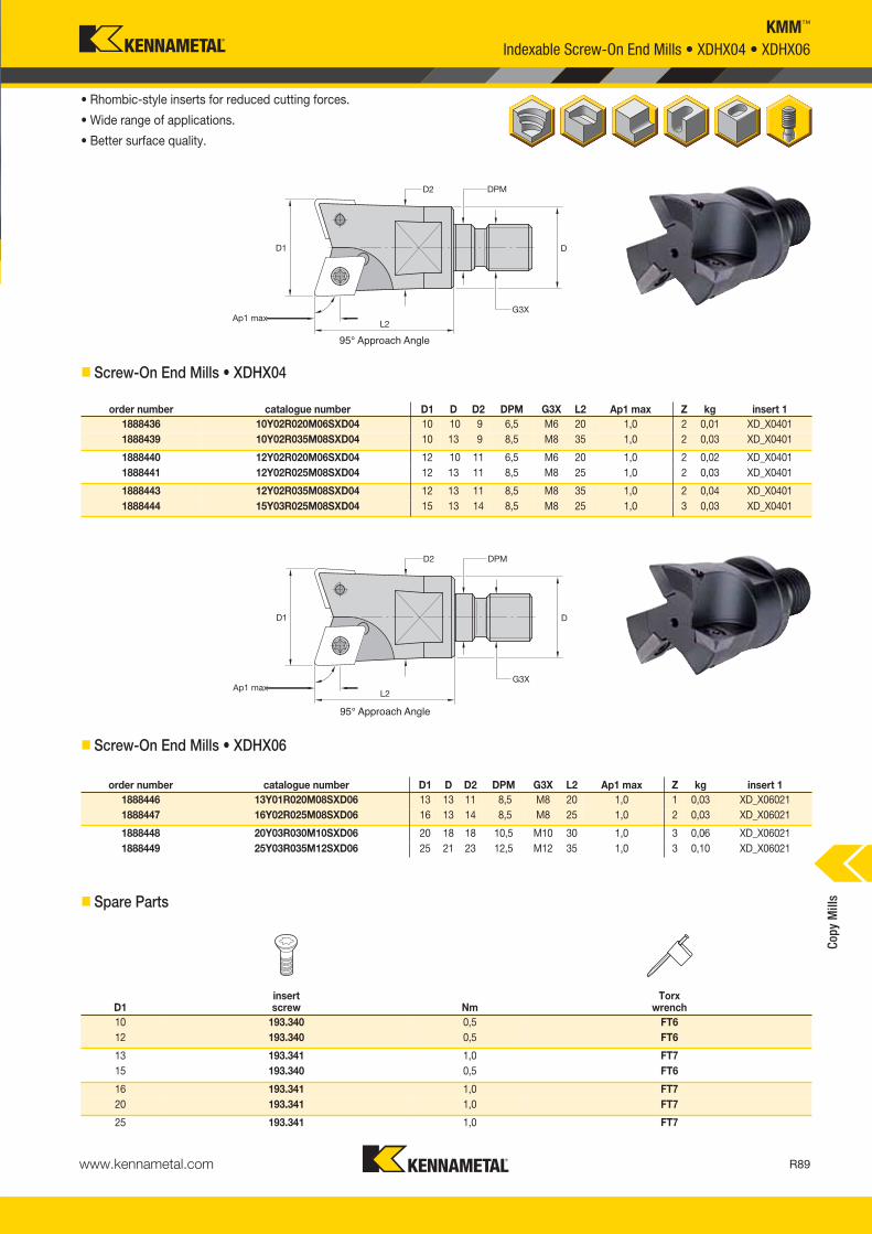
www.kennametal.com R89
KMM™
• Rhombic-style inserts for reduced cutting forces.
• Wide range of applications.
• Better surface quality.
� Screw-On End Mills • XDHX04
� Screw-On End Mills • XDHX06
Indexable Screw-On End Mills • XDHX04 • XDHX06
� Spare Parts
D1insert screw Nm
Torx wrench
10 193.340 0,5 FT612 193.340 0,5 FT6
13 193.341 1,0 FT715 193.340 0,5 FT6
16 193.341 1,0 FT720 193.341 1,0 FT7
25 193.341 1,0 FT7
95° Approach Angle
95° Approach Angle
Copy
Mill
s
order number catalogue number D1 D D2 DPM G3X L2 Ap1 max Z kg insert 11888436 10Y02R020M06SXD04 10 10 9 6,5 M6 20 1,0 2 0,01 XD_X04011888439 10Y02R035M08SXD04 10 13 9 8,5 M8 35 1,0 2 0,03 XD_X0401
1888440 12Y02R020M06SXD04 12 10 11 6,5 M6 20 1,0 2 0,02 XD_X04011888441 12Y02R025M08SXD04 12 13 11 8,5 M8 25 1,0 2 0,03 XD_X0401
1888443 12Y02R035M08SXD04 12 13 11 8,5 M8 35 1,0 2 0,04 XD_X04011888444 15Y03R025M08SXD04 15 13 14 8,5 M8 25 1,0 3 0,03 XD_X0401
order number catalogue number D1 D D2 DPM G3X L2 Ap1 max Z kg insert 11888446 13Y01R020M08SXD06 13 13 11 8,5 M8 20 1,0 1 0,03 XD_X060211888447 16Y02R025M08SXD06 16 13 14 8,5 M8 25 1,0 2 0,03 XD_X06021
1888448 20Y03R030M10SXD06 20 18 18 10,5 M10 30 1,0 3 0,06 XD_X060211888449 25Y03R035M12SXD06 25 21 23 12,5 M12 35 1,0 3 0,10 XD_X06021
KM_Master12_R088_R089_METRIC_EN.qxp:Layout 1 3/7/12 9:52 AM Page R89

www.kennametal.comR90
KMM™
Indexable Screw-On End Mills • XDHX10
• Rhombic-style inserts for reduced cutting forces.
• Wide range of applications.
• Improved surface quality.
95° Approach Angle
� Screw-On End Mills • XDHX10
� Spare Parts
• Rhombic-style inserts for reduced cutting forces.
• Wide range of applications.
• Improved surface quality.
• First choice for long overhangs.
95° Approach Angle
� Shell Mills • XDHX10
D1insert screw Nm
Torx wrench
25 193.342 2,0 FT1535 193.342 2,0 FT15
42 193.342 2,0 FT1552 193.342 2 FT15
order number catalogue number D1 D D6 L Ap1 max Z kg insert 11888194 52A05RS95XD10 52 22 42 50 1,0 5 1,40 XD_X10T3
Copy
Mill
s
order number catalogue number D1 D D2 DPM G3X L2 Ap1 max Z kg insert 11880650 25Y02R036M12SXD10 25 21 22 12,5 M12 36 1,0 2 0,90 XD_X10T3101880651 35Y03R043M16SXD10 35 29 32 17,0 M16 43 1,0 3 0,23 XD_X10T310
1880652 42Y04R043M16SXD10 42 29 39 17,0 M16 43 1,0 4 0,02 XD_X10T310
KM_Master12_R090_R091_METRIC_EN.qxp:Layout 1 3/7/12 9:53 AM Page R90

www.kennametal.com R91
KMM™
Inserts
� Insert Selection Guide
MaterialGroup
Light Machining General Purpose Heavy Machining
Geometry Grade Geometry Grade Geometry GradeP1–P2 .E..LN KC525M .E..LN KC525M — —
P3–P4 .E..LN KTPK20 .E..LN KC510M — —
P5–P6 .E..LN KTPK20 .E..LN KC510M — —
M1–M2 — — — — — —
M3 — — — — — —
K1–K2 .E..LN KTPK20 .E..LN KC510M .E..LN KC510M
K3 .E..LN KTPK20 .E..LN KC510M .E..LN KC510M
N1–N2 — — — — — —
N3 — — — — — —
S1–S2 — — — — — —
S3 — — — — — —
S4 — — — — — —
H1 .E..LN KC510M .E..LN KC510M — —
MaterialGroup
Light Machining General Purpose Heavy Machining
Geometry Grade Geometry Grade Geometry GradeP1–P2 .S..LN KC522M .S..LN KC725M .S..LN KC725M
P3–P4 .S..LN KC510M .S..LN KC522M .S..LN KC522M
P5–P6 .S..LN KC510M .S..LN KC522M .S..LN KC522M
M1–M2 .E..GC KC510M .S..LN KC725M — —
M3 .E..GC KC510M .S..LN KC725M — —
K1–K2 .S..LN KC510M .S..LN KC510M .S..LN KC510M
K3 .S..LN KC510M .S..LN KC510M .S..LN KC510M
N1–N2 .E..GC K110M .E..GC KC510M — —
N3 .E..GC K110M .E..GC KC510M — —
S1–S2 — — — — — —
S3 — — — — — —
S4 — — — — — —
H1 .S..LN KC510M .S..LN KC510M .S..LN KC522M
MaterialGroup
Light Machining General Purpose Heavy Machining
Geometry Grade Geometry Grade Geometry GradeP1–P2 .S..GN KC522M .S..GN KC522M .S..GN KC525M
P3–P4 .S..GN KC510M .S..GN KC522M .S..GN KC522M
P5–P6 .S..GN KC510M .S..GN KC522M .S..GN KC522M
M1–M2 .E..GC KC522M — — — —
M3 .E..GC KC522M — — — —
K1–K2 .T..GN KTPK20 .S..GN KC510M .S..GN KC510M
K3 .T..GN KTPK20 .S..GN KC510M .S..GN KC510M
N1–N2 .E..GC K110M .E..GC KC510M — —
N3 .E..GC K110M .E..GC KC510M — —
S1–S2 — — — — — —
S3 — — — — — —
S4 .E..GC KC522M — — — —
H1 .S..GN KC510M .S..GN KC510M .S..GN KC522M
XD_X04, IC04mm
XD_X06, IC06mm
XD_X10, IC10mmCo
py M
ills
KM_Master12_R090_R091_METRIC_EN.qxp:Layout 1 3/7/12 9:53 AM Page R91

www.kennametal.comR92
KMM™
Indexable Inserts • XD.X...
XDHX-GC XDHX-LNXDHX-GNXDPX-LN
� first choice� alternate choice
• Rhombic-style inserts for reduced cutting forces.
• Wide range of applications.
• Better surface quality.
� XDHX-GC
� XDHX-LN
� XDPX-LN
catalogue number D S L10 Rεε hmcutting edges K
110M
KC
510M
KC
522M
KC
525M
KC
725M
KC
PM
20K
CP
K30
KTP
K20
XDHX040105ELN 4,00 1,59 4,26 0,5 0,03 2 �
XDHX040110ELN 4,00 1,59 4,26 1,0 0,03 2 � �
XDHX060210SLN 6,50 2,38 6,92 1,0 0,06 2 � � �
catalogue number D S L10 Rε hmcutting edges K
110M
KC
510M
KC
522M
KC
525M
KC
725M
KC
PM
20K
CP
K30
KTP
K20
XDHX10T310SGN 10,00 3,97 10,64 1,0 0,09 2 � � �
XDHX10T310TGN 10,00 3,97 10,64 1,0 0,10 2 �
catalogue number D S L10 Rε hmcutting edges K
110M
KC
510M
KC
522M
KC
525M
KC
725M
KC
PM
20K
CP
K30
KTP
K20
XDPX10T310SLN 10,00 3,97 10,65 1,0 0,06 2 � � �
XDPX060210SLN 6,51 2,38 6,92 1,0 0,06 2 � � �
catalogue number D S L10 Rε hmcutting edges K
110M
KC
510M
KC
522M
KC
525M
KC
725M
KC
PM
20K
CP
K30
KTP
K20
XDHX060210EGC 6,50 2,38 6,89 1,0 0,04 2 � �
XDHX10T310EGC 10,00 3,88 10,64 1,0 0,04 2 � � �
� XDHX-GN
P � � � � � �
M � � � � � �
K � � � � � �
N �
S � � �
H �
Copy
Mill
s
KM_Master12_R092_R093_METRIC_EN.qxp:Layout 1 3/7/12 9:49 AM Page R92
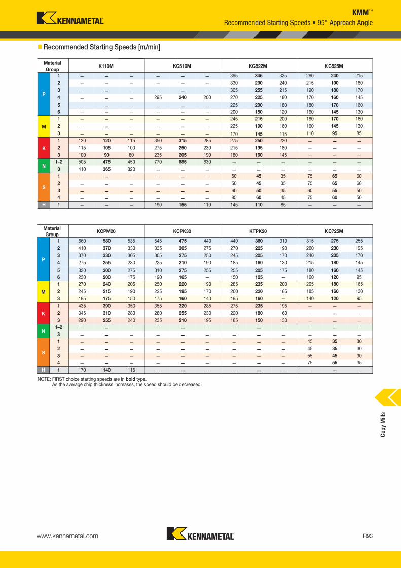
www.kennametal.com R93
KMM™
NOTE: FIRST choice starting speeds are in bold type.As the average chip thickness increases, the speed should be decreased.
� Recommended Starting Speeds [m/min]
MaterialGroup
K110M KC510M KC522M KC525M
KC725M
P
1 — — — — — — 395 345 325 260 240 215
315 275 255
2 — — — — — — 330 290 240 215 190 180
260 230 195
3 — — — — — — 305 255 215 190 180 170
240 205 170
4 — — — 295 240 200 270 225 180 170 160 145
215 180 145
5 — — — — — — 225 200 180 180 170 160
180 160 145
6 — — — — — — 200 150 120 160 145 130
160 120 95
M
1 — — — — — — 245 215 200 180 170 160
205 180 165
2 — — — — — — 225 190 160 160 145 130
185 160 130
3 — — — — — — 170 145 115 110 95 85
140 120 95
K
1 130 120 115 350 315 285 275 250 220 — — —
— — —
2 115 105 100 275 250 230 215 195 180 — — —
— — —
3 100 90 80 235 205 190 180 160 145 — — —
— — —
N1–2 505 475 450 770 685 630 — — — — — —
— — —
3 410 365 320 — — — — — — — — —
— — —
S
1 — — — — — — 50 45 35 75 65 60
45 35 30
2 — — — — — — 50 45 35 75 65 60
45 35 30
3 — — — — — — 60 50 35 60 55 50
55 45 30
4 — — — — — — 85 60 45 75 60 50
75 55 35
H 1 — — — 190 155 110 145 110 85 — — —
— — —
MaterialGroup
KCPM20 KCPK30 KTPK20
P
1 660 580 535 545 475 440 440 360 3102 410 370 330 335 305 275 270 225 1903 370 330 305 305 275 250 245 205 1704 275 255 230 225 210 190 185 160 1305 330 300 275 310 275 255 255 205 1756 230 200 175 190 165 — 150 125 —
M
1 270 240 205 250 220 190 285 235 2002 245 215 190 225 195 170 260 220 1853 195 175 150 175 160 140 195 160 —
K
1 435 390 350 355 320 285 275 235 1952 345 310 280 280 255 230 220 180 1603 290 255 240 235 210 195 185 150 130
N1–2 — — — — — — — — —3 — — — — — — — — —
S
1 — — — — — — — — —2 — — — — — — — — —3 — — — — — — — — —4 — — — — — — — — —
H 1 170 140 115 — — — — — —
Recommended Starting Speeds • 95° Approach Angle
Copy
Mill
s
KM_Master12_R092_R093_METRIC_EN.qxp:Layout 1 3/7/12 9:49 AM Page R93

www.kennametal.comR94
InsertGeometry
Programmed Feed per Tooth (fz)as a % of Radial Depth of Cut (ae) Insert
Geometry10% 20% 30% 40% 50–100%.E..LN 0,09 0,25 0,50 0,06 0,19 0,38 0,06 0,16 0,33 0,05 0,15 0,31 0,05 0,15 0,30 .E..LN
Light Machining
General Purpose
Heavy Machining
InsertGeometry
Programmed Feed per Tooth (fz)as a % of Radial Depth of Cut (ae) Insert
Geometry10% 20% 30% 40% 50–100%.E..GC 0,09 0,29 0,59 0,06 0,22 0,44 0,06 0,19 0,38 0,05 0,18 0,36 0,05 0,18 0,35 .E..GC.S..LN 0,14 0,43 0,68 0,11 0,32 0,51 0,09 0,28 0,45 0,09 0,26 0,42 0,09 0,25 0,41 .S..LN
InsertGeometry
Programmed Feed per Tooth (fz)as a % of Radial Depth of Cut (ae) Insert
Geometry10% 20% 30% 40% 50–100%.E..GC 0,09 0,29 0,59 0,06 0,22 0,44 0,06 0,19 0,38 0,05 0,18 0,36 0,05 0,18 0,35 .E..GC.T..GN 0,17 0,43 0,68 0,13 0,32 0,51 0,11 0,28 0,45 0,10 0,26 0,42 0,10 0,25 0,41 .T..GN.S..GN 0,17 0,43 0,68 0,13 0,32 0,51 0,11 0,28 0,45 0,10 0,26 0,42 0,10 0,25 0,41 .S..GN
KMM™
� Recommended Starting Feeds [mm]
NOTE: Use “Light Machining” values as starting feed rate.
XDHX04
XDHX06
XDHX10
Recommended Starting FeedsCo
py M
ills
KM_Master12_R094_R095_METRIC_EN.qxp:Layout 1 3/7/12 9:51 AM Page R94

Indexable Milling
Check the Kennametal website!
Visit http://www.kennametal.com/milling/ to browse our electronic catalogue any time you’re looking for Kennametal’s best tooling solutions. It’s fast, free, and always available. The online e-catalogue is updated weekly with products and solutions for milling, turning, holemaking, and tooling systems applications.
R95
KM_Master12_R094_R095_METRIC_EN.qxp:Layout 1 3/7/12 9:51 AM Page R95

Coolant nozzles— Precise coolant delivery
to all pockets.
Chip gash serrations— Improved chip flow.
Linear movement clearance— Clearance allowed for
.04 IPT (fz=1mm) when plunging or face milling.
Dropped cutting edge— Improved chip flow.
Platform Features• Nine coolant nozzle sizes enable customised flow by machine tool.
• Unique design is unmatched for chip evacuation.
• Improved performance at a reduced cost per cutting edge.
• Positive geometry lowers cutting force and reduces power requirements, enabling higher feed rates.
• Chip control when slotting.
• Fast and easy insert indexing.
Z-Axis Plunge Mill
Primary ApplicationSpecifically engineered to eliminate vibration and improve metal removal rates in roughing applications. Ideally suited for rough slotting applications in aerospace, general engineering, die and mould, and power generation.
Features and Benefits
www.kennametal.comR96
KM_Master12_R096_R097_METRIC_EN.qxp:Layout 1 3/7/12 9:53 AM Page R96
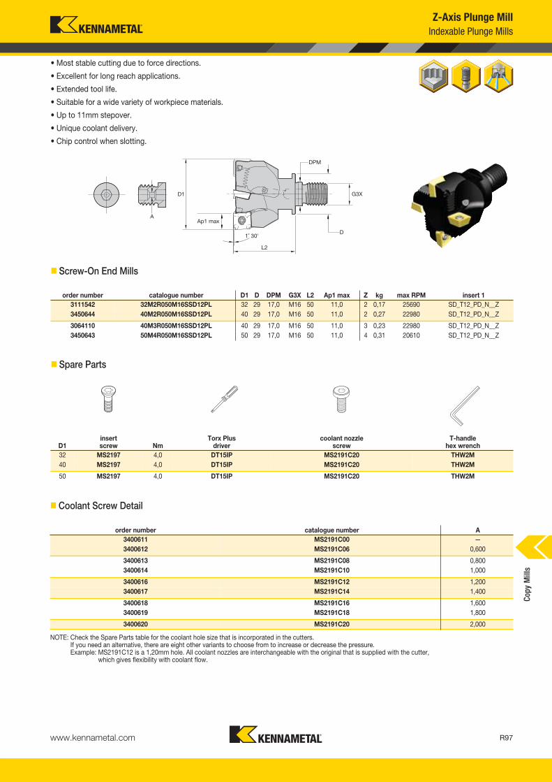
www.kennametal.com R97
Copy
Mill
s
Z-Axis Plunge MillIndexable Plunge Mills
• Most stable cutting due to force directions.
• Excellent for long reach applications.
• Extended tool life.
• Suitable for a wide variety of workpiece materials.
• Up to 11mm stepover.
• Unique coolant delivery.
• Chip control when slotting.
� Screw-On End Mills
� Spare Parts
D1insert screw Nm
Torx Plus driver
coolant nozzle screw
T-handlehex wrench
32 MS2197 4,0 DT15IP MS2191C20 THW2M40 MS2197 4,0 DT15IP MS2191C20 THW2M
50 MS2197 4,0 DT15IP MS2191C20 THW2M
� Coolant Screw Detail
order number catalogue number A3400611 MS2191C00 —3400612 MS2191C06 0,600
3400613 MS2191C08 0,8003400614 MS2191C10 1,000
3400616 MS2191C12 1,2003400617 MS2191C14 1,400
3400618 MS2191C16 1,6003400619 MS2191C18 1,800
3400620 MS2191C20 2,000
NOTE: Check the Spare Parts table for the coolant hole size that is incorporated in the cutters. If you need an alternative, there are eight other variants to choose from to increase or decrease the pressure.Example: MS2191C12 is a 1,20mm hole. All coolant nozzles are interchangeable with the original that is supplied with the cutter,
which gives flexibility with coolant flow.
order number catalogue number D1 D DPM G3X L2 Ap1 max Z kg max RPM insert 13111542 32M2R050M16SSD12PL 32 29 17,0 M16 50 11,0 2 0,17 25690 SD_T12_PD_N__Z3450644 40M2R050M16SSD12PL 40 29 17,0 M16 50 11,0 2 0,27 22980 SD_T12_PD_N__Z
3064110 40M3R050M16SSD12PL 40 29 17,0 M16 50 11,0 3 0,23 22980 SD_T12_PD_N__Z3450643 50M4R050M16SSD12PL 50 29 17,0 M16 50 11,0 4 0,31 20610 SD_T12_PD_N__Z
KM_Master12_R096_R097_METRIC_EN.qxp:Layout 1 3/7/12 9:53 AM Page R97

www.kennametal.comR98
Copy
Mill
sZ-Axis Plunge Mill
Indexable Plunge Mills
• Most stable cutting due to force directions.
• Excellent for long reach applications.
• Extended tool life.
• Suitable for a wide variety of workpiece materials.
• Up to 11mm stepover.
• Unique coolant delivery.
• Chip control when slotting.
� End Mills
order number catalogue number D1 D L L2 Ap1 max Z kg max RPM insert 13402143 32M2R040A25SSD12PL 32 25 200 40 11,0 2 0,69 25690 SD_T1204_PD_N_Z3402144 40M3R040A32SSD12PL 40 32 200 40 11,0 3 1,14 22980 SD_T1204_PD_N_Z
3402145 50M4R040A40SSD12PL 50 40 200 40 11,0 4 1,80 20610 SD_T1204_PD_N_Z
� Spare Parts
D1insert screw Nm
Torx Plus driver
T-handlehex wrench
coolant nozzle screw
32 MS2197 4,0 DT15IP THW2M MS2191C2040 MS2197 4,0 DT15IP THW2M MS2191C20
50 MS2197 4,0 DT15IP THW2M MS2191C20
� Coolant Screw Detail
order number catalogue number A3400611 MS2191C00 —3400612 MS2191C06 0,6
3400613 MS2191C08 0,83400614 MS2191C10 1,0
3400616 MS2191C12 1,23400617 MS2191C14 1,4
3400618 MS2191C16 1,63400619 MS2191C18 1,8
3400620 MS2191C20 2,0
NOTE: Check the Spare Parts table for the coolant hole size that is incorporated in the cutters.If you need an alternative, there are eight other variants to choose from to increase or decrease the pressure.Example: MS2191C12 is a 1,20mm hole. All coolant nozzles are interchangeable with the original that is supplied with the cutter,
which gives flexibility with coolant flow.
KM_Master12_R098_R099_METRIC_EN.qxp:Layout 1 3/7/12 9:52 AM Page R98

www.kennametal.com R99
Copy
Mill
s
Z-Axis Plunge MillIndexable Plunge Mills
• Most stable cutting due to force directions.
• Excellent for long reach applications.
• Extended tool life.
• Suitable for a wide variety of workpiece materials.
• Up to 11mm stepover.
• Unique coolant delivery.
• Chip control when slotting.
� Shell Mills
order number catalogue number D1 D D4 D6 L Ap1 max Z kg max RPM insert 13055230 50A04RS90SD12PL 50 22 — 42 50 11,0 4 0,3 20600 SD_T1204PD_N__Z3063843 50A05RS90SD12PL 50 22 — 42 50 11,0 5 0,4 20600 SD_T1204PD_N__Z
3120265 63A05RS90SD12PL 63 22 — 50 50 11,0 5 0,5 18300 SD_T1204PD_N__Z3120266 63A06RS90SD12PL 63 22 — 50 50 11,0 6 0,6 18300 SD_T1204PD_N__Z
3120267 80A05RS90SD12PL 80 27 — 60 50 11,0 5 1,0 16300 SD_T1204PD_N__Z3120268 80A06RS90SD12PL 80 27 — 60 50 11,0 6 1,0 16300 SD_T1204PD_N__Z
3120269 80A07RS90SD12PL 80 27 — 60 50 11,0 7 1,0 16300 SD_T1204PD_N__Z3120270 100B07RS90SD12PL 100 32 — 80 63 11,0 7 2,1 14600 SD_T1204PD_N__Z
3120271 100B08RS90SD12PL 100 32 — 80 63 11,0 8 2,1 14600 SD_T1204PD_N__Z3120272 100B09RS90SD12PL 100 32 — 80 63 11,0 9 2,2 14600 SD_T1204PD_N__Z
3120573 125B08RS90SD12PL 125 40 — 90 63 11,0 8 3,0 13000 SD_T1204PD_N__Z3120574 125B09RS90SD12PL 125 40 — 90 63 11,0 9 3,1 13000 SD_T1204PD_N__Z
3120575 125B10RS90SD12PL 125 40 — 90 63 11,0 10 3,1 13000 SD_T1204PD_N__Z3120576 160C09RS90SD12PL 160 40 67 90 63 11,0 9 3,2 11500 SD_T1204PD_N__Z
3120577 160C10RS90SD12PL 160 40 67 90 63 11,0 10 3,2 11500 SD_T1204PD_N__Z3120578 160C12RS90SD12PL 160 40 67 90 63 11,0 12 3,3 11500 SD_T1204PD_N__Z
� Spare Parts
D1insert screw Nm
Torx Plus driver
coolant nozzle screw
T-handlehex wrench
coolant lock screw assembly
coolant shower plate assembly
socket-head cap screwwith coolant groove
50 MS2197 4,0 DT15IP MS2191C12 THW2M — — MS1242CG63 MS2197 4,0 DT15IP MS2191C12 THW2M — — MS1242CG
80 MS2197 4,0 DT15IP MS2191C12 THW2M — — MS2038CG100 MS2197 4,0 DT15IP MS2191C10 THW2M MS2189C — —
125 MS2197 4,0 DT15IP MS2191C10 THW2M MS2187C — —160 MS2197 4,0 DT15IP MS2191C20 THW2M — MCCM16001 —
� Coolant Screw Detail
order number catalogue number A3400611 MS2191C00 —3400612 MS2191C06 0,6
3400613 MS2191C08 0,83400614 MS2191C10 1,0
3400616 MS2191C12 1,23400617 MS2191C14 1,4
3400618 MS2191C16 1,63400619 MS2191C18 1,8
3400620 MS2191C20 2,0
NOTE: Check the Spare Parts table for the coolant hole size that is incorporated in the cutters.If you need an alternative, there are eight other variants to choose from to increase or decrease the pressure.Example: MS2191C12 is a 1,20mm hole. All coolant nozzles are interchangeable with the original that is supplied with the cutter,
which gives flexibility with coolant flow.
KM_Master12_R098_R099_METRIC_EN.qxp:Layout 1 3/7/12 9:52 AM Page R99

www.kennametal.comR100
Copy
Mill
sZ-Axis Plunge MillIndexable Plunge Mills • JIS
• Most stable cutting due to force directions.
• Excellent for long reach applications.
• Extended tool life.
• Suitable for a wide variety of workpiece materials.
• Up to 11mm stepover.
• Unique coolant delivery.
• Chip control when slotting.
• Metric cutter diameters with inch bore sizes.
� Shell Mills • Coarse Pitch • Japanese Industry Standard (JIS)
Dorder number catalogue number D1 mm in D6 L Ap1 max Z kg max RPM insert 1
3640178 80A05RS90SD12PL-J 80 25,400 1.000 60 50 11 5 1,05 16300 SD_T1204_PD_N__Z3640179 80A06RS90SD12PL-J 80 25,400 1.000 60 50 11 6 1,06 16300 SD_T1204_PD_N__Z
3640180 80A07RS90SD12PL-J 80 25,400 1.000 60 50 11 7 1,06 16300 SD_T1204_PD_N__Z3640181 100B07RS90SD12PL-J 100 31,750 1.250 80 63 11 7 2,14 14600 SD_T1204_PD_N__Z
3640182 100B08RS90SD12PL-J 100 31,750 1.250 80 63 11 8 2,21 14600 SD_T1204_PD_N__Z3640293 100B09RS90SD12PL-J 100 31,750 1.250 80 63 11 9 2,25 14600 SD_T1204_PD_N__Z
3640294 125B08RS90SD12PL-J 125 38,100 1.500 90 63 11 8 2,79 13000 SD_T1204_PD_N__Z3640295 125B09RS90SD12PL-J 125 38,100 1.500 90 63 11 9 2,85 13000 SD_T1204_PD_N__Z
3640296 125B10RS90SD12PL-J 125 38,100 1.500 90 63 11 10 2,88 13000 SD_T1204_PD_N__Z3640297 160B09RS90SD12PL-J 160 50,800 2.000 90 63 11 9 3,69 11500 SD_T1204_PD_N__Z
3640298 160B10RS90SD12PL-J 160 50,800 2.000 90 63 11 10 3,69 11500 SD_T1204_PD_N__Z3640299 160B12RS90SD12PL-J 160 50,800 2.000 90 63 11 12 3,76 11500 SD_T1204_PD_N__Z
� Spare Parts
D1insert screw Nm
Torx Plus driver
coolant nozzle screw
coolant lock screw assembly
T-handlehex wrench
socket-head cap screwwith coolant groove
80 MS2197 4,0 DT15IP MS2191C12 — THW2M MS2038CG80 MS2197 4,0 DT15IP MS2191C10 — THW2M MS2038CG
100 MS2197 4,0 DT15IP MS2191C10 MS2220C THW2M —125 MS2197 4,0 DT15IP MS2191C08 — THW2M —
125 MS2197 4,0 DT15IP MS2191C10 — THW2M —160 MS2197 4,0 DT15IP MS2191C20 — THW2M —
� Coolant Screw Detail
order number catalogue number A3400611 MS2191C00 —3400612 MS2191C06 0,6
3400613 MS2191C08 0,83400614 MS2191C10 1,0
3400616 MS2191C12 1,23400617 MS2191C14 1,4
3400618 MS2191C16 1,63400619 MS2191C18 1,8
3400620 MS2191C20 2,0
NOTE: Check the Spare Parts table for the coolant hole size that is incorporated in the cutters.If you need an alternative, there are eight other variants to choose from to increase or decrease the pressure.Example: MS2191C12 is a 1,20mm hole. All coolant nozzles are interchangeable with the original that is supplied with the cutter,
which gives flexibility with coolant flow.
KM_Master12_R100_R101_METRIC_EN.qxp:Layout 1 3/28/12 10:45 AM Page R100

www.kennametal.com R101
Copy
Mill
s
Z-Axis Plunge MillInserts
� Insert Selection Guide
MaterialGroup
Light Machining General Purpose Heavy Machining
Geometry Grade Geometry Grade Geometry GradeP1–P2 .E..GDZ KC725M .S..GDZ KC725M .E..HPZ KC725M
P3–P4 .S..GDZ KCPK30 .E..HPZ KCPK30 .S..HPZ KCPK30
P5–P6 .S..GDZ KCPK30 .E..HPZ KCPM20 .S..HPZ KCPM20
M1–M2 .E..GDZ KC725M .S..GDZ KC725M .E..HPZ KC725M
M3 .S..GDZ KCPK30 .E..HPZ KCPK30 .S..HPZ KCPK30
K1–K2 .E..GDZ KCPK30 .S..GDZ KCPK30 .E..HPZ KCPK30
K3 .S..GDZ KCPK30 .E..HPZ KCPK30 .S..HPZ KCPK30
N1–N2 .F..LE KC410M .F..LE KC410M .F..LE KC410M
N3 — — — — — —
S1–S2 .E..GDZ KC725M .S..GDZ KC725M .E..HPZ KC725M
S3 .S..GDZ KC725M .E..HPZ KC725M .S..HPZ KC725M
S4 .E..HPZ KC725M .S..HPZ KC725M — —
H1 — — — — — —
P � � � �
M � � � �
K � � �
N �
S � �
H
catalogue number L10 S BS Rε hmcutting edges K
C41
0MK
C52
2MK
C72
5MK
CP
M20
KC
PK
30SDCT120412PDFRLE 12,70 4,76 2,70 1,2 0,02 4 �
SDCT120412PDFLLE 12,70 4,76 2,70 1,2 0,02 4 �
catalogue number L10 S Rε hmcutting edges K
C41
0MK
C52
2MK
C72
5MK
CP
M20
KC
PK
30
SDET120412PDENGDZ 12,70 4,76 1,2 0,06 4 � � �
SDET120412PDSNGDZ 12,70 4,76 1,2 0,13 4 � � �
catalogue number D L10 S Rε hmcutting edges K
C41
0MK
C52
2MK
C72
5MK
CP
M20
KC
PK
30
SDPT120412PDENHPZ 12,70 12,70 4,76 1,2 0,08 4 � � � �
SDPT120412PDSNHPZ 12,70 12,70 4,76 1,2 0,15 4 � � � �
SDCT-LE SDET-GDZ SDPT-HPZ
SDLT-LE SDET-GDZ SDPT-HPZ
� first choice� alternate choice
� SDCT-LE
� SDET-GDZ
� SDPT-HPZ
Indexable Inserts • KSSZR 90° • Z-Axis
KM_Master12_R100_R101_METRIC_EN.qxp:Layout 1 3/28/12 10:45 AM Page R101

www.kennametal.comR102
Copy
Mill
sZ-Axis Plunge Mill
MaterialGroup
KC410M KC522M KC725M KCPM20 KCPK30
P
1 — — — 395 345 325 315 275 255 660 580 535 545 475 4402 — — — 330 290 240 260 230 195 410 370 330 335 305 2753 — — — 305 255 215 240 205 170 370 330 305 305 275 2504 — — — 270 225 180 215 180 145 275 255 230 225 210 1905 — — — 225 200 180 180 160 145 330 300 275 310 275 2556 — — — 200 150 120 160 120 95 230 200 175 190 165 —
M
1 — — — 245 215 200 205 180 165 270 240 205 250 220 1902 — — — 225 190 160 185 160 130 245 215 190 225 195 1703 — — — 170 145 115 140 120 95 195 175 150 175 160 140
K
1 — — — 275 250 220 — — — 435 390 350 355 320 2852 — — — 215 195 180 — — — 345 310 280 280 255 2303 — — — 180 160 145 — — — 290 255 240 235 210 195
N1–2 1460 1300 1195 — — — — — — — — — — — — 3 — — — — — — — — — — — — — — —
S
1 — — — 50 45 35 45 35 30 — — — — — — 2 — — — 50 45 35 45 35 30 — — — — — — 3 — — — 60 50 35 55 45 30 — — — — — — 4 — — — 85 60 45 75 55 35 — — — — — —
H 1 — — — — — — — — — — — — — — —
NOTE: FIRST choice starting speeds are in bold type.As the average chip thickness increases, the speed should be decreased.
InsertGeometry
Programmed Feed per Tooth (fz)as a % of Radial Depth of Cut (ae) Insert
Geometry10% 20% 30% 40% 50–100%.F..LE — — — — — — — — — — — — 0,05 0,10 0,20 .F..LE
.E..GDZ — — — — — — — — — — — — 0,09 0,25 0,41 .E..GDZ
.S..GDZ — — — — — — — — — — — — 0,10 0,25 0,41 .S..GDZ
.E..HPZ — — — — — — — — — — — — 0,10 0,25 0,41 .E..HPZ
.S..HPZ — — — — — — — — — — — — 0,10 0,25 0,41 .S..HPZ
NOTE: Use “Light Machining” values as starting feed rate.
Light Machining
General Purpose
Heavy Machining
� Recommended Starting Speeds [m/min]
� Recommended Starting Feeds [mm]
Recommended Starting Speeds and Feeds
KM_Master12_R102_R103_METRIC_EN.qxp:Layout 1 3/7/12 9:50 AM Page R102

www.kennametal.com R103
Copy
Mill
s
Z-Axis Plunge MillMethods of Manufacture
� Z-Axis
Best Machining PracticesWhen finishing a workpiece, you sometimes have to use a Z-axis solutionversus a conventional end mill solution to get the best results.
When the length-to-diameter ratio protrudes farther than 3:1, you will needto use a Z-axis solution. This is when the end mill starts to vibrate and thesurface finish and noise are unacceptable.
When vibration occurs, the feed rates are compromised, which normallyslows down the production of the workpiece.
ProgrammingAt this point, there is very little software for this type of application on the market. We suggest that a simple macro is created for this type of application, which can be recalled and the “X” and “Y” movement changed.
The process can be repeated, so the cutter can be removed from theworkpiece in the rapid (G00) movement. Tool life will be improved by not allowing the insert to rub on the retract path.
SlottingThere are several differing ways to machine a slot in a component using the Z-axis cutter solution.
Figure 1This shows the typical way of machining a slot. The movements are feeding down and straight back up (Z+) in the same axis and will have a negative impact on the insert radii (cutting edge) that could lead to premature failure of the nose radii. When looking at the component, it will show the rapid travel in the Z+ direction. This will highlight the spiral of the insert/cutter operating at a high feed. It looks similar to an oil groove spiralling upwards.
Figure 3Align the cutter with the centre of the slot on the component and define the stepover that's required. Move the Y-axis into a position for the first cut, take the first pass to a depth in the Z-axis, and when itreaches the bottom of the slot, program a 2-axis move to retract thecutting edge for the workpiece.
The 2-axis move will move the Z-axis in a positive direction at 45° (.010")away from the component, and the Y-axis will move away from theworkpiece by the same amount at the same angle. Now the cutter can be retracted from the component, and the insert will not rub on the retract move.
Move the cutter to the left of the slot to define the new position and makethe cut. When reaching the base, a 3-axis move will need to be made.Again, the Z-axis will be in a positive direction at 45° (.010"), and thecorresponding Y-axis will move away the same respective amount from the wall.
The insert/cutter has now moved away from the workpiece, and the rapidZ+ can take place. Repeat the process on the other side of the slot,remembering the X-axis move needs to be moving the other way.
NOTE: When starting the process, it's better to start at the centre of theslot. After the slot has been defined, you no longer need to put thecutter on the center path. Passes from both sides create the slotwidth and enable clearance for the subsequent moves, so theinsert/cutter can be moved away from the side walls of the material.
Figure 2Using a cutter that is smaller than the slot width allows the insert/cutter tobe removed from the material when (G00) rapid motion is retracting fromthe component. Because this type of cutter can be used across varioustypes of machines, assume a 50mm (2.00") diameter cutter is being usedto machine a slot of 63mm (2.50") wide on a vertical 3-axis machine.
(continued)
KM_Master12_R102_R103_METRIC_EN.qxp:Layout 1 3/7/12 9:50 AM Page R103

www.kennametal.comR104
Copy
Mill
s
External ProfilingThis artwork represents the typical application for this type of process.Move into the cut and follow the external profile of the workpiece. Whenmoving the cutter back to the start position, it's always advisable to movethe insert from contacting the workpiece. This should be done with a 2- or3-axis move (use .010") at 0,25mm. All axes moving in a Z+ direction willstop the rubbing in the retract move.
Internal ProfilingWhen taking the first pass of a depth, there is also a need to move theinsert/cutter away from the material on the retract motion. Each of thepasses that follow should adopt the same method on the retract move.
Follow the cutter path until the component has been finished.
Machining Around a RadiiThis artwork shows the cutter taking a larger radial width of cut. Whenmoving down in the Z-axis, the insert could start to take a larger radialwidth of cut. Typical application could be the manufacture of a turbineblade from a rectangular piece of material. Always remember that it'sadvisable to move the insert/cutter away from the material on the retract motion.
Z-Axis Plunge MillMethods of Manufacture
� Z-Axis (continued)
Linear Plunge MillingEntering the cutter along a parallel axis, the radial width of cut needs to be defined because the cutter might need to move away from theworkpiece material.
If the radial width of cut takes more than 60% of the cutter diameter, it ismore difficult to remove the insert/cutter because the machine programwants to move the cutter upwards to (G00) Z+. When taking more than60% of the cutter diameter, the material is enveloping the cutter and isdifficult to remove because a cusp has been created.
It is suggested to make the radial width of cut 50% of the cutter diameterto allow the insert/cutter to be removed without any problems.
KM_Master12_R104_R105_METRIC_EN.qxp:Layout 1 3/7/12 9:53 AM Page R104

www.kennametal.com
Experience the advantages at your Authorised Kennametal Distributor or at www.kennametal.com.
Screw-On Milling Cutter Adaptors The Complete Solution to Milling
• High metal removal rates.• High runout accuracy.• Maximum performance capability.• Optimising productivity with long reach and short
overhang to support all types of applications.• Cutter is kept on centre for precision and maximum
performance compared to Weldon® shank system.• Ability to extend with standard offering extensions and reducers.• Ground face contact for rigidity and accuracy.
Features and Benefits
KM_Master12_R104_R105_METRIC_EN.qxp:Layout 1 3/7/12 9:53 AM Page R105

www.kennametal.comR106
KDMR™ • Multifunction Cutter
Primary ApplicationAn extensive offering of versatile mills that can also drill.
Features and Benefits
Platform Features• Just two grades needed for a wide variety of materials.
• Reduced shank for machining down a side wall.
• Metric and inch sizes available.
• Reduced shank diameters for access down long side walls.
• Extensive product portfolio.
• Use compressed air when drilling for improved chip evacuation.
• Full two-edge line with improved stability.
• Lower cutting resistance and long shank types are available.
• New grade provides stability and longer tool life.
• Good chip evacuation, even when slant milling and drilling.
1
2
3
4
67
8
5
Vertical Milling/Plunging
Helical Milling
Ramping and Helical Milling
Pocketing
Shouldering/Profiling
Drilling
Slotting
Ramping
1
2
3
4
5
6
7
8
KM_Master12_R106_R107_METRIC_EN.qxp:Layout 1 3/7/12 9:50 AM Page R106

www.kennametal.com R107
Fig. 5 Fig. 6
KDMR™
Multifunctional Cutter • Metric
• Low cutting forces.
• Reduced shank diameters for access down long side walls.
• Excellent chip evacuation, even when machining on an angle.
• When drilling, use (1) as the effective number of teeth (ZU).
• Milling to the maximum axial depth of (Ap2), we have (2) effective teeth.
� Weldon® Shank • Metric
order number catalogue number D1 D L L2 Ap1 max Ap2 max Z Z U figure kg insert 1 insert 23587022 KDMR16S1680WL 16 16 80 31 19 4,5 4 2 FIG 5 0,11 GOMT08T208ERLD JOMT08T208ERLF3587055 KDMR17S1680WL 17 16 80 31 19 4,5 4 2 FIG 6 0,12 GOMT08T208ERLD JOMT08T208ERLF
3587059 KDMR20S2085WL 20 20 85 35 22 6,0 4 2 FIG 5 0,23 GOMT100308ERLD JOMT100308ERLF3587062 KDMR21S2085WL 21 20 85 35 22 6,0 4 2 FIG 6 0,25 GOMT100308ERLD JOMT100308ERLF
3587066 KDMR25S2595WL 25 25 95 40 28 7,5 4 2 FIG 5 0,33 GOMT13T308ERLD JOMT13T308ERLF3587069 KDMR26S2595WL 26 25 95 40 28 7,5 4 2 FIG 6 0,35 GOMT13T308ERLD JOMT13T308ERLF
3587071 KDMR32S32110WL 32 32 110 50 36 9,5 4 2 FIG 5 0,58 GOMT160408ERLD JOMT160408ERLF3587075 KDMR33S32110WL 33 32 110 50 36 9,5 4 2 FIG 6 0,60 GOMT160408ERLD JOMT160408ERLF
3587078 KDMR40S32130WL 40 32 130 55 42 7,5 7 2 FIG 6 0,88 GOMT13T308ERLD JOMT13T308ERLF3587082 KDMR50S40140WL 50 40 140 70 54 9,5 7 2 FIG 6 1,43 GOMT160408ERLD JOMT160408ERLF
NOTE: Axial depth of cut above (Ap2) value, use (1) as the effective number of teeth.See separate chart for drilling depths.Use compressed air when drilling for improved chip evacuation.
� Spare Parts
Copy
Mill
s
D1insert screw Nm
Torx driver
anti-seize lube
16 MS2211 3,5 DT6 ASL3GT17 MS2211 0,5 DT6 ASL3GT
20 MS2212 0,5 DT8 ASL3GT21 MS2212 1,2 DT8 ASL3GT
25 MS2213 1,2 DT10 ASL3GT26 MS2213 2,0 DT10 ASL3GT
32 MS2214 2,0 DT15 ASL3GT33 MS2214 3,5 DT15 ASL3GT
40 MS2213 3,5 DT10 ASL3GT50 MS2214 2,0 DT15 ASL3GT
KM_Master12_R106_R107_METRIC_EN.qxp:Layout 1 3/7/12 9:50 AM Page R107

www.kennametal.comR108
Fig. 1 Fig. 2
KDMR™
Multifunctional Cutter • Metric
• Low cutting forces.
• Reduced shank diameters for access down long side walls.
• Excellent chip evacuation, even machining on an angle.
• When drilling, use (1) as the effective number of teeth (ZU).
• Milling to the maximum axial depth of (Ap2), we have (2) effective teeth.
� Standard Length
order number catalogue number D1 D L L2 Ap1 max Ap2 max Z Z U figure kg insert 1 insert 23587019 KDMR16S16 16 16 120 31 19 4,5 4 2 FIG 1 0,22 GOMT08T208ERLD JOMT08T208ERLF3587053 KDMR17S16 17 16 120 31 19 4,5 4 2 FIG 1 0,20 GOMT08T208ERLD JOMT08T208ERLF
3587056 KDMR20S20 20 20 130 35 22 6,0 4 2 FIG 1 0,37 GOMT100308ERLD JOMT100308ERLF3587060 KDMR21S20 21 20 130 35 22 6,0 4 2 FIG 1 0,37 GOMT100308ERLD JOMT100308ERLF
3587063 KDMR25S25 25 25 140 40 28 7,5 4 2 FIG 1 0,57 GOMT13T308ERLD JOMT13T308ERLF3587067 KDMR26S25 26 25 140 40 28 7,5 4 2 FIG 1 0,55 GOMT13T308ERLD JOMT13T308ERLF
3587070 KDMR32S32 32 32 150 50 36 9,5 4 2 FIG 1 0,93 GOMT160408ERLD JOMT160408ERLF3587074 KDMR33S32 33 32 150 50 36 9,5 4 2 FIG 1 0,95 GOMT160408ERLD JOMT160408ERLF
3587077 KDMR40S32 40 32 160 55 42 7,5 7 2 FIG 2 1,08 GOMT13T308ERLD JOMT13T308ERLF3587080 KDMR50S40 50 40 170 70 54 9,5 7 2 FIG 2 1,64 GOMT160408ERLD JOMT160408ERLF
NOTE: Axial depth of cut above (Ap2) value, use (1) as the effective number of teeth.See separate chart for drilling depths.Use compressed air when drilling for improved chip evacuation.
� Long Length Cutters
order number catalogue number D1 D L L2 Ap1 max Ap2 max Z Z U figure kg insert 1 insert 23587020 KDMR16S16140L 16 16 140 51 19 4,5 4 2 FIG 1 0,24 GOMT08T208ERLD JOMT08T208ERLF3587057 KDMR20S20150L 20 20 150 53 22 6,0 4 2 FIG 1 0,43 GOMT100308ERLD JOMT100308ERLF
3587064 KDMR25S25170L 25 25 170 70 28 7,5 4 2 FIG 1 0,67 GOMT13T308ERLD JOMT13T308ERLF3587072 KDMR32S32180L 32 32 180 80 36 9,5 4 2 FIG 1 1,09 GOMT160408ERLD JOMT160408ERLF
� Spare Parts
D1insert screw Nm
Torx driver
anti-seize lube
16 MS2211 0,5 DT6 ASL3GT17 MS2211 0,5 DT6 ASL3GT
20 MS2212 1,2 DT8 ASL3GT21 MS2212 1,2 DT8 ASL3GT
25 MS2213 2,0 DT10 ASL3GT26 MS2213 2,0 DT10 ASL3GT
32 MS2214 3,5 DT15 ASL3GT33 MS2214 3,5 DT15 ASL3GT
40 MS2213 2,0 DT10 ASL3GT50 MS2214 — DT15 ASL3GT
Copy
Mill
s
KM_Master12_R108_R109_METRIC_EN.qxp:Layout 1 3/7/12 9:53 AM Page R108

www.kennametal.com R109
KDMR™
Multifunctional Cutter • Metric
• Low cutting forces.
• Reduced shank diameters for access down long side walls.
• Excellent chip evacuation, even machining on an angle.
• When drilling, use (1) as the effective number of teeth (ZU).
• Milling to the maximum axial depth of (Ap2), we have (2) effective teeth.
� Long Shank
order number catalogue number D1 D L L2 Ap1 max Ap2 max Z Z U figure kg insert 1 insert 23587021 KDMR16S16190 16 16 190 61 19 4,5 4 2 FIG 1 0,32 GOMT08T208ERLD JOMT08T208ERLF3587054 KDMR17S16190 17 16 190 31 19 4,5 4 2 FIG 1 0,34 GOMT08T208ERLD JOMT08T208ERLF
3587058 KDMR20S20200 20 20 200 63 22 6,0 4 2 FIG 1 0,54 GOMT100308ERLD JOMT100308ERLF3587061 KDMR21S20200 21 20 200 35 22 6,0 4 2 FIG 1 0,58 GOMT100308ERLD JOMT100308ERLF
3587065 KDMR25S25220 25 25 220 80 28 7,5 4 2 FIG 1 0,85 GOMT13T308ERLD JOMT13T308ERLF3587068 KDMR26S25220 26 25 220 40 28 7,5 4 2 FIG 1 0,88 GOMT13T308ERLD JOMT13T308ERLF
3587073 KDMR32S32230 32 32 230 90 36 9,5 4 2 FIG 1 1,40 GOMT160408ERLD JOMT160408ERLF3587076 KDMR33S32230 33 32 230 50 36 9,5 4 2 FIG 1 1,38 GOMT160408ERLD JOMT160408ERLF
3587079 KDMR40S32240 40 32 240 55 42 7,5 7 2 FIG 2 1,57 GOMT13T308ERLD JOMT13T308ERLF3587081 KDMR50S40250 50 40 250 70 54 9,5 7 2 FIG 2 2,47 GOMT160408ERLD JOMT160408ERLF
NOTE: Axial depth of cut above (Ap2) value, use (1) as the effective number of teeth.See separate chart for drilling depths.Use compressed air when drilling for improved chip evacuation.
� Spare Parts
D1insert screw Nm
Torx driver
anti-seize lube
16 MS2211 3,5 DT6 ASL3GT17 MS2211 0,5 DT6 ASL3GT
20 MS2212 0,5 DT8 ASL3GT21 MS2212 1,2 DT8 ASL3GT
25 MS2213 1,2 DT10 ASL3GT26 MS2213 2,0 DT10 ASL3GT
32 MS2214 2,0 DT15 ASL3GT33 MS2214 3,5 DT15 ASL3GT
40 MS2213 3,5 DT10 ASL3GT50 MS2214 2,0 DT15 ASL3GT
Fig. 1 Fig.2
Copy
Mill
s
KM_Master12_R108_R109_METRIC_EN.qxp:Layout 1 3/7/12 9:53 AM Page R109

www.kennametal.comR110
KDMR™
Inserts
� Insert Selection Guide
MaterialGroup
Light Machining General Purpose Heavy Machining
Geometry Grade Geometry Grade Geometry GradeP1–P2 .LD/.LF KC720M .LD/.LF KC720M .LD/.LF KC720M
P3–P4 .LD/.LF KC720M .LD/.LF KC720M .LD/.LF KC720M
P5–P6 .LD/.LF KC720M .LD/.LF KC720M .LD/.LF KC720M
M1–M2 .LD/.LF KC720M .LD/.LF KC720M .LD/.LF KC720M
M3 .LD/.LF KC720M .LD/.LF KC720M .LD/.LF KC720M
K1–K2 .LD/.LF KC505M .LD/.LF KC505M .LD/.LF KC505M
K3 .LD/.LF KC505M .LD/.LF KC505M .LD/.LF KC505M
N1–N2 — — — — — —
N3 — — — — — —
S1–S2 — — — — — —
S3 — — — — — —
S4 — — — — — —
H1 — — — — — —
P � �
M �
K �
NSH
catalogue number S W L10 Rε hmcutting edges K
C50
5MK
C72
0M
JOMT08T208ERLF 2,78 5,14 8,50 0,8 0,06 2 � �
JOMT100308ERLF 3,18 6,42 10,20 0,8 0,06 2 � �
JOMT13T308ERLF 3,70 8,05 13,20 0,8 0,06 2 � �
JOMT160408ERLF 4,76 9,67 16,70 0,8 0,06 2 � �
Indexable Insert • JOMT-LF • GOMT-LD
JOMT-LF GOMT-LD
� first choice� alternate choice
� JOMT • Side Insert
� GOMT • Centre Insert
catalogue number S W L10 Rε hmcutting edges K
C50
5MK
C72
0M
GOMT08T208ERLD 2,78 5,21 8,70 0,8 0,06 2 � �
GOMT100308ERLD 3,30 6,56 10,70 0,8 0,06 2 � �
GOMT13T308ERLD 3,85 8,36 13,20 0,8 0,06 2 � �
GOMT160408ERLD 4,76 10,03 16,70 0,8 0,06 2 � �
Copy
Mill
s
KM_Master12_R110_R111_METRIC_EN.qxp:Layout 1 3/7/12 9:52 AM Page R110

www.kennametal.com R111
KDMR™
MaterialGroup
KC505M KC720M
P
1 — — — 260 240 2152 — — — 240 215 1903 — — — 215 190 1704 360 260 215 190 180 1705 360 260 215 170 145 1206 350 240 190 120 95 95
M
1 — — — 240 215 1902 — — — 190 170 1453 — — — 145 120 95
K
1 190 170 150 — — — 2 175 155 135 — — —3 115 95 75 — — —
N1–2 — — — — — — 3 — — — — — —
S
1 — — — — — — 2 — — — — — —3 — — — — — — 4 — — — — — —
H 1 — — — — — —
NOTE: FIRST choice starting speeds are in bold type.As the average chip thickness increases, the speed should be decreased.
InsertGeometry
Programmed Feed per Tooth (fz)as a % of Radial Depth of Cut (ae) Insert
Geometry10% 20% 30% 40% 50–100%.LD/.LF 0,14 0,34 0,51 0,11 0,25 0,38 0,09 0,22 0,33 0,09 0,21 0,31 0,05 0,20 0,30 .LD/.LF
NOTE: Use “Light Machining” values as starting feed rate.
Light Machining
General Purpose
Heavy Machining
� Recommended Starting Speeds [m/min]
� Recommended Starting Feeds [mm]
end mill applicable insert for each cutter diameter
D1 side insert quantity centre insert quantity
Ø 16 JOMT08T208ERLF 3 GOMT08T208ERLD 1
Ø 17 JOMT08T208ERLF 3 GOMT08T208ERLD 1
Ø 20 JOMT100308ERLF 3 GOMT100308ERLD 1
Ø 21 JOMT100308ERLF 3 GOMT100308ERLD 1
Ø 25 JOMT13T308ERLF 3 GOMT13T308ERLD 1
Ø 26 JOMT13T308ERLF 3 GOMT13T308ERLD 1
Ø 32 JOMT160408ERLF 3 GOMT160408ERLD 1
Ø 33 JOMT160408ERLF 3 GOMT160408ERLD 1
Ø 40 JOMT13T308ERLF 6 GOMT13T308ERLD 1
Ø 50 JOMT160408ERLF 6 GOMT160408ERLD 1
� Insert Cross Reference
Recommended Starting Speeds and Feeds • 90° Approach Angle • Technical Information
Copy
Mill
s
KM_Master12_R110_R111_METRIC_EN.qxp:Layout 1 3/7/12 9:52 AM Page R111
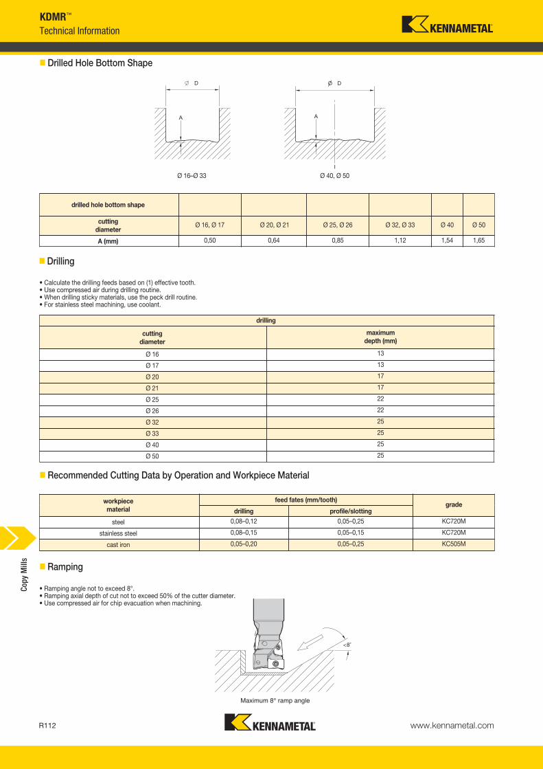
www.kennametal.comR112
• Calculate the drilling feeds based on (1) effective tooth.• Use compressed air during drilling routine.• When drilling sticky materials, use the peck drill routine.• For stainless steel machining, use coolant.
workpiece material
feed fates (mm/tooth)grade
drilling profile/slotting
steel 0,08–0,12 0,05–0,25 KC720M
stainless steel 0,08–0,15 0,05–0,15 KC720M
cast iron 0,05–0,20 0,05–0,25 KC505M
drilling
cuttingdiameter
maximum depth (mm)
Ø 16 13
Ø 17 13
Ø 20 17
Ø 21 17
Ø 25 22
Ø 26 22
Ø 32 25
Ø 33 25
Ø 40 25
Ø 50 25
Ø 16–Ø 33 Ø 40, Ø 50
drilled hole bottom shape
cuttingdiameter
Ø 16, Ø 17 Ø 20, Ø 21 Ø 25, Ø 26 Ø 32, Ø 33 Ø 40 Ø 50
A (mm) 0,50 0,64 0,85 1,12 1,54 1,65
Maximum 8° ramp angle
• Ramping angle not to exceed 8°.• Ramping axial depth of cut not to exceed 50% of the cutter diameter.• Use compressed air for chip evacuation when machining.
� Drilled Hole Bottom Shape
� Drilling
� Recommended Cutting Data by Operation and Workpiece Material
� Ramping
KDMR™
Technical InformationCo
py M
ills
KM_Master12_R112_R113_METRIC_EN.qxp:Layout 1 3/7/12 9:51 AM Page R112

www.kennametal.com
Experience the advantages at your Authorised Kennametal Distributor or at www.kennametal.com.
KM4X™
Features and Benefits• Run jobs at significantly faster feeds and speeds than is achievable with other spindle interfaces.• Unique use of clamping force and interference level increases clamping capability 2–3 times. • You experience lower cost of ownership, increased throughput, and superior results.
Load-Deflection chart
Def
lect
ion
[mm
] @ 1
50m
m
Bending Moment [Nm]
The Latest Innovation in Spindle Interface Technology! Dramatically increase your metal removal rates when machining high-temperature alloys!
KM_Master12_R112_R113_METRIC_EN.qxp:Layout 1 3/7/12 9:51 AM Page R113

KIPR™ and KSSR™ • Ceramic Milling Cutters
Primary ApplicationThe Kennametal ceramic milling platform has been specifically engineered to machine high-temperature alloys, PH series, stainless steel, and hardened materials. With excellent productivity through the massive reduction of machining time, Kennametal ceramics can run more than 10 times faster than comparable carbide grades.
Features and Benefits
Unbeatable Productivity• Engineering to provide outstanding metal removal rates and productivity
in nickel-based and/or cobalt-based alloys, stellites, stainless steel, and PH series through HSM.
• High axial and radial runout accuracy.
• Improved insert clearance and thickness tolerance to increase overall performance.
• New clamping system design provides higher spare part tool life and reliability and higher RPM.
Usability and Offering• Three grades and three insert sizes available to cover
a wide range of applications.
• Wide diameter range with shell mills, end mills, and Screw-On cutters from diameter 16mm.
• High clearance on the cutters for superior ramping capacities.
• Through-coolant option in all the cutters. Only for air use.
www.kennametal.comR114
KM_Master12_R114_R115_METRIC_EN.qxp:Layout 1 3/7/12 9:50 AM Page R114

www.kennametal.com R115
KIPR-RP RPGN..Screw-On End Mills
• For machining high-temp alloys, PH stainless, stainless steels, and hardened materials.
• Excellent productivity through massive reduction of machining time.
• Face milling, pocketing, and ramping capabilities.
• Through-body coolant delivery for internal air supply only.
� Screw-On End Mills
� Spare Parts
D1 max clampclampscrew Nm
Torx driver
Torx driver
20 KCI1 191.924 1,9 DT9 —20 KCI2 191.725 3,5 DT15 —
25 KCI2 191.725 3,5 DT15 —32 KCI3M 193.409 6,0 — TTP20
Copy
Mill
s
order number catalogue number D1 max D1 D DPM G3X L2 WF Ap1 max Zmax
ramp angle kg max RPM insert 14052782 KIPR020RP09MF02 20 11 18 10,5 M10 30 14 4,8 2 13.0° 0,05 23040 RP_N0903___4052781 KIPR020RP06MF03 20 14 18 10,5 M10 30 14 3,2 3 10.0° 0,05 33325 RP_N0602___
4052843 KIPR025RP09MF03 25 16 21 12,5 M12 35 18 4,8 3 8.0° 0,08 20610 RP_N0903___3101753 KIPR032RP12MF03 32 20 29 17,0 M16 45 22 6,3 3 4.2° 0,18 20420 RP_N1204___
KM_Master12_R114_R115_METRIC_EN.qxp:Layout 1 3/7/12 9:50 AM Page R115

www.kennametal.comR116
order number catalogue number D1 max D1 D L L2 Ap1 max Zmax
ramp angle kg max RPM insert 13617418 KIPR016RP06CF02 16 10 16 75 26 3,2 2 14.0° 0,10 37260 RP_N0602___4052780 KIPR020RP09CF02 20 11 20 82 31 4,8 2 13.0° 0,16 23040 RP_N0903___
3617416 KIPR020RP06CF03 20 14 20 82 31 3,2 3 10.0° 0,17 33325 RP_N0602___3617415 KIPR025RP09CF03 25 16 25 96 39 4,8 3 8.0° 0,30 20610 RP_N0903___
3101754 KIPR032RP12CF03 32 20 32 110 50 6,3 3 4.2° 0,56 20420 RP_N1204___3101755 KIPR040RP12CF04 40 28 32 110 49 6,3 4 2.8° 0,61 18260 RP_N1204___
KIPR-RP RPGN..Cylindrical End Mills
• For machining high-temp alloys, PH stainless, stainless steels, and hardened materials.
• Excellent productivity through massive reduction of machining time.
• Face milling, pocketing, and ramping capabilities.
• Through-body coolant delivery for internal air supply only.
� Cylindrical End Mills
� Spare Parts
D1 max clampclampscrew Nm
Torx driver
Torx driver
16 KCI1 191.924 1,9 DT9 —20 KCI1 191.924 1,9 DT9 —
20 KCI2 191.725 3,5 DT15 —25 KCI2 191.725 3,5 DT15 —
32 KCI3M 193.409 6,0 — TTP2040 KCI3M 193.409 6,0 — TTP20
Copy
Mill
s
KM_Master12_R116_R117_METRIC_EN.qxp:Layout 1 3/7/12 9:52 AM Page R116

www.kennametal.com R117
order number catalogue number D1 max D1 D D6 L Ap1 max Zmax
ramp angle kg max RPM insert 13101756 KSSR050RP12CF04 50 37 16 44 50 6,3 4 2.0° 0,41 16340 RP_N1204___3101757 KSSR063RP12CF04 63 50 22 50 50 6,3 4 1.4° 0,69 14550 RP_N1204___
3101758 KSSR080RP12CF05 80 67 27 60 50 6,3 5 1.0° 1,09 12900 RP_N1204___3101759 KSSR100RP12CF06 100 87 32 80 50 6,3 6 .8° 1,84 11550 RP_N1204___
KSSR-RPGN..Shell Mills
• For machining high-temp alloys, PH stainless, stainless steels, and hardened materials.
• Excellent productivity through massive reduction of machining time.
• Face milling, pocketing, and ramping capabilities.
• Through-body coolant delivery for internal air supply only.
� Shell Mills
� Spare Parts
D1 max clampclampscrew Nm
Torx Plus wrench
50 KCI3M 193.409 6,0 TTP2063 KCI3M 193.409 6,0 TTP20
80 KCI3M 193.409 6,0 TTP20100 KCI3M 193.409 6,0 TTP20
Copy
Mill
s
KM_Master12_R116_R117_METRIC_EN.qxp:Layout 1 3/7/12 9:52 AM Page R117

www.kennametal.comR118
KIPR- • KSSR- • RPGN.. • High Temp
P � �
M �
KNS � � � �
H �
Indexable Ceramic Inserts • KIPR-RP • KSSR-RP
RPGN
� first choice� alternate choice
� RPGN
catalogue number D S KY
S30
KY
SP30
KY
SM10
KY
HS1
0
RPGN060200E 6,35 2,38 � � � �
RPGN090300E 9,53 3,18 � � � �
RPGN090300T01020 9,53 3,18 �
RPGN120400E 12,70 4,76 � � � �
RPGN120400T01020 12,70 4,76 �
Copy
Mill
s
NOTE: A — Use these tools with the appropriate equipment/machines. Machines have to be covered for safety reasons: Hot flowing chips and loud noises are involved, which is common during the milling process.
B — Use only air flows as coolant method.
C — Higher RPMs are involved; use balanced toolholder for higher tool life and safer operation.
D — Consider increasing the fz in hard machining when smaller ap are applied.
Inserts
� Insert Selection Guide
RPGN06… High Temp
MaterialGroup
Light Machining General Purpose Heavy MachiningGeometry Grade Geometry Grade Geometry Grade
P1–P2 — — — — — —P3–P4 — — — — — —P5–P6 ..E KYSP30 ..E KYSP30 ..E KYSP30M1–M2 — — — — — —
M3 ..E KYSM10 ..E KYSM10 ..E KYSM10K1–K2 — — — — — —
K3 — — — — — —N1–N2 — — — — — —
N3 — — — — — —S1–S2 ..E KYS30 ..E KYS30 ..E KYS30
S3 ..E KYS30 ..E KYS30 ..E KYS30S4 — — — — — —H1 ..E KYHS10 ..E KYHS10 — —
RPGN09… High Temp
MaterialGroup
Light Machining General Purpose Heavy MachiningGeometry Grade Geometry Grade Geometry Grade
P1–P2 — — — — — —P3–P4 — — — — — —P5–P6 ..E KYSP30 ..E KYSP30 ..E KYSP30M1–M2 — — — — — —
M3 ..E KYSM10 ..E KYSM10 ..E KYSM10K1–K2 — — — — — —
K3 — — — — — —N1–N2 — — — — — —
N3 — — — — — —S1–S2 ..E KYS30 ..E KYS30 ..T KYS30
S3 ..E KYS30 ..T KYS30 ..T KYS30S4 — — — — — —H1 ..E KYHS10 ..E KYHS10 — —
RPGN12… High Temp
MaterialGroup
Light Machining General Purpose Heavy MachiningGeometry Grade Geometry Grade Geometry Grade
P1–P2 — — — — — —P3–P4 — — — — — —P5–P6 ..E KYSP30 ..E KYSP30 ..E KYSP30M1–M2 — — — — — —
M3 ..E KYSM10 ..E KYSM10 ..E KYSM10K1–K2 — — — — — —
K3 — — — — — —N1–N2 — — — — — —
N3 — — — — — —S1–S2 ..E KYS30 ..E KYS30 ..T KYS30
S3 ..E KYS30 ..T KYS30 ..T KYS30S4 — — — — — —H1 ..E KYHS10 ..E KYHS10 — —
KM_Master12_R118_R119_METRIC_EN.qxp:Layout 1 5/14/12 9:08 AM Page R118

www.kennametal.com R119
KIPR- • KSSR- • RPGN06 • High Temp
MaterialGroup
KYHS10 KYSM10 KYSP30 KYS30
P
1 — — — — — — — — — — — —
2 — — — — — — — — — — — —
3 — — — — — — — — — — — —
4 — — — — — — — — — — — —
5 — — — 1205 975 725 915 730 550 — — — 6 — — — 1205 975 725 915 730 550 — — —
M
1 — — — 1205 975 725 — — — — — —
2 — — — 1140 915 — — — — — — — 3 — — — 840 730 — — — — — — —
K
1 — — — — — — — — — — — —
2 — — — — — — — — — — — — 3 — — — — — — — — — — — —
N1–2 — — — — — — — — — — — — 3 — — — — — — — — — — — —
S
1 510 400 295 1065 870 675 805 660 510 805 660 510
2 510 400 295 1065 870 675 805 660 510 805 660 510
3 730 620 510 1550 1260 970 1170 950 730 1170 950 730
4 — — — — — — — — — — — — H 1 365 310 240 — — — — — — — — —
Light Machining
General Purpose
Heavy Machining
� Recommended Starting Speeds [m/min]
� Recommended Starting Feeds [mm] • RPGN06..
Recommended Starting Speeds and Feeds
At 3,18 Axial Depth of Cut (ap)
At 0,79 Axial Depth of Cut (ap)
At 1,59 Axial Depth of Cut (ap)
NOTE: Use “Light Machining” values as starting feed rate.
At 0,40 Axial Depth of Cut (ap)
NOTE: FIRST choice starting speeds are in bold type.As the average chip thickness increases, the speed should be decreased.
Copy
Mill
s
InsertGeometry
Programmed Feed per Tooth (fz)as a % of Radial Depth of Cut (ae) Insert
Geometry10% 20% 30% 40% 50–100%..E 0,12 0,13 0,17 0,09 0,10 0,13 0,08 0,09 0,11 0,07 0,08 0,10 0,07 0,08 0,10 ..E
InsertGeometry
Programmed Feed per Tooth (fz)as a % of Radial Depth of Cut (ae) Insert
Geometry10% 20% 30% 40% 50–100%..E 0,14 0,15 0,20 0,10 0,11 0,15 0,09 0,10 0,13 0,09 0,09 0,12 0,08 0,09 0,12 ..E
InsertGeometry
Programmed Feed per Tooth (fz)as a % of Radial Depth of Cut (ae) Insert
Geometry10% 20% 30% 40% 50–100%..E 0,18 0,20 0,26 0,14 0,15 0,19 0,12 0,13 0,17 0,11 0,12 0,16 0,11 0,12 0,15 ..E
InsertGeometry
Programmed Feed per Tooth (fz)as a % of Radial Depth of Cut (ae) Insert
Geometry10% 20% 30% 40% 50–100%..E 0,25 0,27 0,35 0,19 0,20 0,26 0,16 0,18 0,23 0,15 0,17 0,22 0,15 0,16 0,21 ..E
KM_Master12_R118_R119_METRIC_EN.qxp:Layout 1 5/14/12 9:08 AM Page R119

www.kennametal.comR120
Light Machining
General Purpose
Heavy Machining
KIPR- • KSSR- • RPGN09 • RPGN12 • High Temp
� Recommended Starting Feeds [mm] • RPGN09..
At 4,76 Axial Depth of Cut (ap)
At 0,60 Axial Depth of Cut (ap)
At 1,19 Axial Depth of Cut (ap)
At 2,38 Axial Depth of Cut (ap)
At 1,59 Axial Depth of Cut (ap)
NOTE: Use “Light Machining” values as starting feed rate.
At 3,18 Axial Depth of Cut (ap)
At 0,79 Axial Depth of Cut (ap)
At 6,35 Axial Depth of Cut (ap)
� Recommended Starting Feeds [mm] • RPGN12..
Recommended Starting FeedsCo
py M
ills
InsertGeometry
Programmed Feed per Tooth (fz)as a % of Radial Depth of Cut (ae) Insert
Geometry10% 20% 30% 40% 50–100%..E 0,12 0,13 0,17 0,09 0,10 0,13 0,08 0,09 0,11 0,07 0,08 0,10 0,07 0,08 0,10 ..E..T 0,17 0,20 0,26 0,13 0,15 0,19 0,11 0,13 0,17 0,10 0,12 0,16 0,10 0,12 0,15 ..T
InsertGeometry
Programmed Feed per Tooth (fz)as a % of Radial Depth of Cut (ae) Insert
Geometry10% 20% 30% 40% 50–100%..E 0,14 0,15 0,20 0,10 0,11 0,15 0,09 0,10 0,13 0,09 0,09 0,12 0,08 0,09 0,12 ..E..T 0,20 0,24 0,30 0,15 0,18 0,22 0,13 0,15 0,19 0,12 0,14 0,18 0,12 0,14 0,18 ..T
InsertGeometry
Programmed Feed per Tooth (fz)as a % of Radial Depth of Cut (ae) Insert
Geometry10% 20% 30% 40% 50–100%..E 0,18 0,20 0,26 0,14 0,15 0,19 0,12 0,13 0,17 0,11 0,12 0,16 0,11 0,12 0,15 ..E..T 0,26 0,31 0,39 0,19 0,23 0,29 0,17 0,20 0,25 0,16 0,19 0,24 0,15 0,19 0,23 ..T
InsertGeometry
Programmed Feed per Tooth (fz)as a % of Radial Depth of Cut (ae) Insert
Geometry10% 20% 30% 40% 50–100%..E 0,25 0,27 0,35 0,19 0,20 0,26 0,16 0,18 0,23 0,15 0,17 0,22 0,15 0,16 0,21 ..E..T 0,35 0,42 0,53 0,26 0,32 0,40 0,23 0,28 0,35 0,21 0,26 0,32 0,21 0,25 0,32 ..T
InsertGeometry
Programmed Feed per Tooth (fz)as a % of Radial Depth of Cut (ae) Insert
Geometry10% 20% 30% 40% 50–100%..E 0,12 0,13 0,17 0,09 0,10 0,13 0,08 0,09 0,11 0,07 0,08 0,10 0,07 0,08 0,10 ..E..T 0,17 0,26 0,29 0,13 0,20 0,22 0,11 0,17 0,19 0,10 0,16 0,18 0,10 0,16 0,17 ..T
InsertGeometry
Programmed Feed per Tooth (fz)as a % of Radial Depth of Cut (ae) Insert
Geometry10% 20% 30% 40% 50–100%..E 0,14 0,15 0,20 0,10 0,11 0,15 0,09 0,10 0,13 0,09 0,09 0,12 0,08 0,09 0,12 ..E..T 0,20 0,31 0,33 0,15 0,23 0,25 0,13 0,20 0,22 0,12 0,19 0,20 0,12 0,18 0,20 ..T
InsertGeometry
Programmed Feed per Tooth (fz)as a % of Radial Depth of Cut (ae) Insert
Geometry10% 20% 30% 40% 50–100%..E 0,18 0,20 0,26 0,14 0,15 0,19 0,12 0,13 0,17 0,11 0,12 0,16 0,11 0,12 0,15 ..E..T 0,26 0,40 0,44 0,19 0,30 0,33 0,17 0,26 0,29 0,16 0,24 0,27 0,15 0,24 0,26 ..T
InsertGeometry
Programmed Feed per Tooth (fz)as a % of Radial Depth of Cut (ae) Insert
Geometry10% 20% 30% 40% 50–100%..E 0,25 0,27 0,35 0,19 0,20 0,26 0,16 0,18 0,23 0,15 0,17 0,22 0,15 0,16 0,21 ..E..T 0,35 0,55 0,60 0,26 0,41 0,45 0,23 0,36 0,39 0,21 0,33 0,37 0,21 0,33 0,36 ..T
KM_Master12_R120_R121_METRIC_EN.qxp:Layout 1 5/14/12 9:08 AM Page R120

www.kennametal.com R121
order number catalogue number D1 max D1 D D6 L Ap1 max Z kg max RPM insert 13101760 KSSR050RN12CF03 50 37 16 42 50 6,0 3 0,38 20500 RNGN1207003101761 KSSR063RN12CF04 63 50 22 54 50 6,0 4 0,60 16600 RNGN120700
3101762 KSSR080RN12CF05 80 67 27 64 50 6,0 5 0,96 13500 RNGN1207003101763 KSSR100RN12CF06 100 87 32 84 50 6,0 6 1,53 11200 RNGN120700
3101764 KSSR125RN12CF07 125 112 40 94 63 6,0 7 2,70 9000 RNGN1207003101765 KSSR160RN12CF09 160 147 40 114 63 6,0 9 4,85 7000 RNGN120700
D1 max clampclampscrew washer Nm
Torx wrench
50 555.205 MS1221 191.279 9,0 TT2563 555.205 MS1221 191.279 9,0 TT25
80 555.205 MS1221 191.279 9,0 TT25100 555.205 MS1221 191.279 9,0 TT25
125 555.205 MS1221 191.279 9,0 TT25160 555.205 MS1221 191.279 9,0 TT25
KSSR™ • RNGN..Shell Mills
• First choice for face milling high-temp alloys and hardened materials up to 60 HRC.
• Excellent productivity through massive reduction of machining time.
� Shell Mills • RNGN 1207
� Spare Parts
Copy
Mill
s
KM_Master12_R120_R121_METRIC_EN.qxp:Layout 1 5/14/12 9:08 AM Page R121
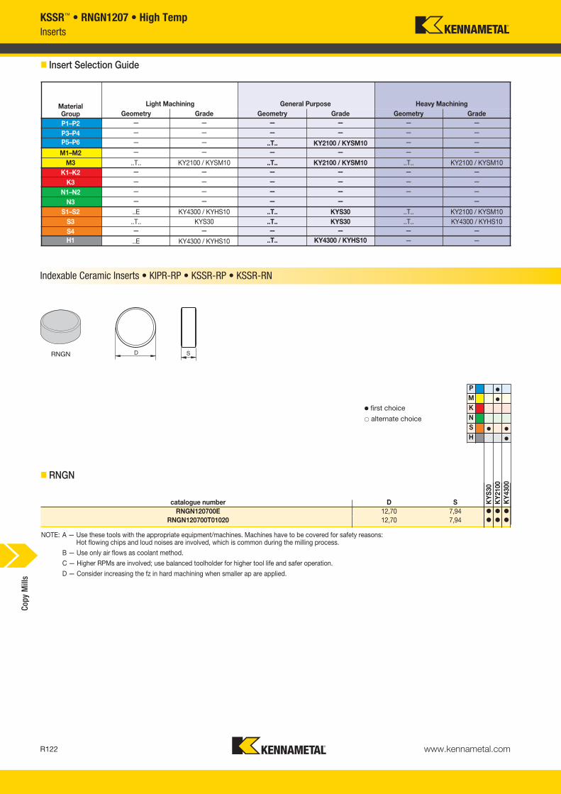
www.kennametal.comR122
KSSR™ • RNGN1207 • High TempInserts
� Insert Selection Guide
MaterialGroup
Light Machining General Purpose Heavy MachiningGeometry Grade Geometry Grade Geometry Grade
P1–P2 — — — — — —
P3–P4 — — — — — — P5–P6 — — ..T.. KY2100 / KYSM10 — —
M1–M2 — — — — — —
M3 ..T.. KY2100 / KYSM10 ..T.. KY2100 / KYSM10 ..T.. KY2100 / KYSM10K1–K2 — — — — — —
K3 — — — — — —
N1–N2 — — — — — —
N3 — — — — —
S1–S2 ..E KY4300 / KYHS10 ..T.. KYS30 ..T.. KY2100 / KYSM10S3 ..T.. KYS30 ..T.. KYS30 ..T.. KY4300 / KYHS10S4 — — — — — — H1 ..E KY4300 / KYHS10 ..T.. KY4300 / KYHS10 — —
catalogue number D S KY
S30
KY
2100
KY
4300
RNGN120700E 12,70 7,94 � � �
RNGN120700T01020 12,70 7,94 � � �
� first choice� alternate choice
� RNGN
NOTE: A — Use these tools with the appropriate equipment/machines. Machines have to be covered for safety reasons: Hot flowing chips and loud noises are involved, which is common during the milling process.
B — Use only air flows as coolant method.
C — Higher RPMs are involved; use balanced toolholder for higher tool life and safer operation.
D — Consider increasing the fz in hard machining when smaller ap are applied.
Indexable Ceramic Inserts • KIPR-RP • KSSR-RP • KSSR-RN
P �
M �
KNS � �
H �
Copy
Mill
s
RNGN
KM_Master12_R122_R123_METRIC_EN.qxp:Layout 1 3/7/12 9:52 AM Page R122

www.kennametal.com R123
MaterialGroup
KY4300 KY2100 KYS30
P
1 — — — — — — — — —
2 — — — — — — — — —
3 — — — — — — — — —
4 — — — — — — — — —
5 — — — — — — — — —
6 — — — — — — — — —
M
1 — — — — — — — — —
2 — — — — — — — — —
3 — — — — — — — — —
K
1 — — — — — — — — —
2 — — — — — — — — —
3 — — — — — — — — —
N1–2 — — — — — — — — — 3 — — — — — — — — —
S
1 510 400 295 1065 870 675 805 660 510
2 510 400 295 1065 870 675 805 660 510
3 730 620 510 1550 1260 970 1170 950 730
4 — — — — — — — — —
H 1 365 310 240 — — — — — —
InsertGeometry
Programmed Feed per Tooth (fz)as a % of Radial Depth of Cut (ae) Insert
Geometry10% 20% 30% 40% 50–100%..E 0,09 0,10 0,11 0,07 0,08 0,09 0,06 0,07 0,07 0,06 0,06 0,07 0,06 0,06 0,07 ..E..T.. 0,17 0,26 0,28 0,13 0,19 0,21 0,11 0,17 0,19 0,10 0,16 0,17 0,10 0,16 0,17 ..T..
InsertGeometry
Programmed Feed per Tooth (fz)as a % of Radial Depth of Cut (ae) Insert
Geometry10% 20% 30% 40% 50–100%..E 0,11 0,12 0,13 0,08 0,09 0,10 0,07 0,08 0,09 0,07 0,07 0,08 0,07 0,07 0,08 ..E..T.. 0,20 0,30 0,33 0,15 0,22 0,25 0,13 0,20 0,21 0,12 0,18 0,20 0,12 0,18 0,20 ..T..
InsertGeometry
Programmed Feed per Tooth (fz)as a % of Radial Depth of Cut (ae) Insert
Geometry10% 20% 30% 40% 50–100%..E 0,14 0,16 0,17 0,11 0,12 0,13 0,09 0,10 0,11 0,09 0,10 0,10 0,09 0,09 0,10 ..E..T.. 0,26 0,39 0,43 0,19 0,29 0,32 0,17 0,26 0,28 0,16 0,24 0,26 0,15 0,23 0,26 ..T..
InsertGeometry
Programmed Feed per Tooth (fz)as a % of Radial Depth of Cut (ae) Insert
Geometry10% 20% 30% 40% 50–100%..E 0,20 0,21 0,23 0,15 0,16 0,18 0,13 0,14 0,15 0,12 0,13 0,14 0,12 0,13 0,14 ..E..T.. 0,35 0,54 0,59 0,26 0,40 0,44 0,23 0,35 0,38 0,21 0,33 0,36 0,21 0,32 0,35 ..T..
Light Machining
General Purpose
Heavy Machining
KSSR™ • RNGN1207 • High Temp
NOTE: Use “Light Machining” values as starting feed rate.
� Recommended Starting Speeds [m/min]
At 3,18 Axial Depth of Cut (ap)
At 1,59 Axial Depth of Cut (ap)
At 0,79 Axial Depth of Cut (ap)
Recommended Starting Speeds and Feeds
At 6,35 Axial Depth of Cut (ap)
NOTE: FIRST choice starting speeds are in bold type.As the average chip thickness increases, the speed should be decreased.
� Recommended Starting Feeds [mm]
Copy
Mill
s
KM_Master12_R122_R123_METRIC_EN.qxp:Layout 1 3/7/12 9:52 AM Page R123


