

Kin
etro
l Van
e A
ctua
tors
Kinetrol's rigorous quality
program is approved to ISO
9001:2000 and AS/EN 9100
ensuring that each unit is
manufactured to the highest
standards.
Certificate No. FM22163
Kinetrol Actuators, Springs
and Accessories are now
approved up to ATEX
Category 1.
Single moving partSimplest and most reliable mechanism for
quarter-turn rotary actuation.
Direct mounting control modulesFail-safe spring returns, limit switches,
positioners, solenoid valves, all just bolt on
direct, no brackets needed.
No cranks or gearingNo power loss or backlash - allows accurate
positioning.
Durable corrosion resistant finish
Long maintenance-free lifeUp to 4 million operations guaranteed.
Compact - space saving - efficientBest torque/size package available, fast
operating speeds, best air consumption,
proven design.
Hundreds of thousands of unitsin trouble free service all over the world.
Choice of male or female output drivesquare - easy to interface toapplication
Applications
Operation or positioning of ball, butterfly and plug valves, ventilation dampers and automatic
doors. Uses also include movement and positioning of components during manufacture - in fact
anything that needs to be turned through 90° or less, automatically or by remote control.
For ordering codes see page 38For catalogue index see page 501

2
Mo
du
lar ‘add
on
’co
ntro
l un
itsAP Positioner3 - 15psi (0.2 to 1 bar) air
signal controls main air
supply to TURN, STOP or
HOLD the actuator vane in
proportional response to
that air signal. Limit switch
and angle retransmit
options (details pages
11/12).
3 Stop PositionerProvides two endstop
positions and a mid-range
setpoint anywhere within
the 90° span. Easy setpoint
adjustment and integral
position feedback options
(details page 14).
Manual Override SquareMost actuators and
combination assemblies
have a square drive shaft
(except those with
positioners) extension at
the top useable for
emergency operation
(details page 19/20).
SolenoidOptional integral pneumatic
solenoid valve for
actuators. Various types of
electrical, environmental
and explosion proof
requirements covered
(details page 6).
Actuator15 sizes covering torque
range 5 lbf in (0.5 Nm) to
168,000 lbf in (19140 Nm).
Operating air pressure
range 20 psi (1.4 bar) to
100 psi (7 bar). Adjustable
stops standard. Restricted
travel stops and DIN/ISO
versions available for most
models (details pages 23 to
37).
GearboxGeared manual override on
all models from 05 to 16
inclusive (details page 21).
Mounting BracketA comprehensive range of
brackets provides for most
ball, plug and butterfly
valves (details page 41).
Visual IndicatorGives visual indication of
valve position, as standard
except OMO, 08, 16, 18, 20
and 30.
I/P Controller4 - 20mA electrical signal
controls main air supply to
pneumatic positioner as
alternative to air signal
control (details page 13).
EL ElectropneumaticpositionerA single unit gives smooth
accurate control in response
to a 4 to 20mA signal. Limit
switch and angle retransmit
options in same housing
(details page 15/16).
Clear Cone PositionMonitorGives 360° and overhead
position indication, available
on actuator and EHD models
05, 07, 09 and 10, limit
switch boxes from 05 and on
AP and EL positioners
(details page 6).
Universal Limit Switch BoxWeather tight unit with up to
4 micro-switches for remote
position indication or control
use. Optional switches for
flame proof / explosion proof
needs and high visibility
Clear cone position monitor
(details page 7/8).
Spring Return UnitClock type spring gives
reliable fail safe operation
with high torque output
throughout spring stroke, yet
has easy adjustment to suit
application (details page
3/4/5).
180° ConverterCompact units give constant
torque output through up to
200° travel (details page
17/18).
ISO AdaptorThe patented ISO adaptor
provides easy conversion
from a Kinetrol male drive to
an ISO flange interface for
ultimate mounting flexibility
(details page 22).

Kin
etro
l Van
e A
ctua
tors
Lowest Torque LossTypically 20% through 90° yields extra torque
through spring stroke - enables the selection
of smaller actuators (see diagram)
Reliable low stress range clock type spring
Separate housing for modular assemblyeasily retrofitted
Sealed, non-breathing housingProtects spring in corrosive environments
Adjustable pretension for 'balanced' airand spring stroke torquesVarious combinations available for
balanced/optimised torques at various air
pressures
Keeper plates available to ensure safehandling of pretensioned springs
All models available with ISO/DIN femaledrive and mounting (except models 01 & 02)
Springs guaranteed against failure forlifetime of actuator.
The diagram shows the torquerequirement of a typical ballvalve under normal conditions.The typical torque outputcharacteristics of Kinetrol andRack and Pinion actuators,both sized to overcome thevalve's breakout torque, arealso illustrated. The graphsdemonstrate that the Kinetrolactuator will exceed the torquerequirement of the valvethroughout the entire strokewhilst the rack and pinion unitwill fail to reseat the valve.
The higher torque lossesassociated with the rack andpinion actuators (torque losscan be as high as 70%) dictatethe selection of larger units toensure complete reseating.
Spring housing cut away
3

4
Mo
du
lar ‘add
on
’co
ntro
l un
itsDirection of Spring Action
Spring units are available for either clockwise or
counter clockwise spring action. For spring unit
alone direction is determined looking down at
the unit from the end opposite to that which
interfaces with an actuator.
Suffix - 020 = clockwise
Suffix - 030 = counter clockwise
Direction of actuator/spring assemblies is
determined by looking at whole assembly from
non-output end.
Asymmetrical Torque Applications
If high torque is required in one direction and
lower torque in the other direction this can be set
up easily by changing spring pretension to be
higher or lower as required. Air stroke torque will
always be double-acting torque (at air pressures
available) less spring pretension torque.
Pretension Setting
Factory assembled actuator/spring return
assemblies have the spring pretension set for
'balanced' torque output when the actuator is
operated by air at 80psi (5.5bar).
Factory assemblies can be preset for different
air pressures below 80psi (5.5 bar) on request.
Spring return units supplied separate from
actuators are also pretensioned for 80psi (5.5
bar) air operation unless otherwise stated.
Keeper Plates
These are provided on all pretensioned spring
return units supplied separate from actuators.
They are also available as spare parts.
A keeper plate must always be used to restrain
spring tension whenever a spring unit case is
dismantled.
Low air pressure applications Materials specifications
If air pressure available for actuator operation
is less than 50psi (3.5 bar) 'balanced' torque
output on air and spring strokes is still possible
by using a spring return unit from a smaller
actuator size. Listed below are factory
assembled options of this kind.
Replace the '*' used in ordering codes below
with a '2' (clockwise) or '3' (counter clockwise)
depending on direction of spring action
required.
Spring Casing Models 01-12 pressure die-cast
in BS1004 zinc alloy. Models 14,
16, 18, 20 & 30 aluminium alloy
LM25.
Finish Epoxy stove enamel.
Spring Clock type spring steel.
Square Steel, zinc plated.
Mount Holes Same as matching actuator
except model 01, low pressure
combinations & ISO drive
versions. (see page 43).
See pages 47 & 48 for full torque details on all models
Ordering Code Description030-1*0-5600 03 actuator with one 02 spring unit
050-1*0-5300 05 actuator with one 02 spring unit
070-1*0-4000 07 actuator with one 05 spring unit
080-1*0-4100 08 actuator with one 07 spring unit
090-1*0-4200 09 actuator with one 07 spring unit
100-1*0-5800 10 actuator with one 09 spring unit
120-1*0-4300 12 actuator with one 09 spring unit
120-1*0-4400 12 actuator with two 09 spring units
140-1*0-4900 14 actuator with two 12 spring units
140-1*0-5000 14 actuator with one 12 spring unit
160-1*0-6000 16 actuator with one 14 spring
unit and one 12 spring unit
160-1*0-6100 16 actuator with one 14 spring unit
180-1*0-7000 18 actuator with one 16 spring unit
200-1*0-7200 20 actuator with two 16 spring units
200-1*0-7300 20 actuator with three 16 spring units
300-1*0-7600 30 actuator with three 16 spring units
300-1*0-7700 30 actuator with four 16 spring units
300-1*0-7800 30 actuator with five 16 spring units

5
Fem
ale
Dri
ve U
nit
s
Direction of Spring Action
Female spring units are available for
either clockwise or counter clockwise
spring action. Although a female drive
spring is mounted below the actuator
direction is still determined looking down
at the top of the assembly from the non-
output end.
Suffix - F020 = clockwise
Suffix - F030 = counter clockwise
Female serrated insert drivemodels
Various female springs are available
with insert drives to give maximum
flexibility when mounting and includes
the following features:
- Can accommodate large diameter
valve stems
- Deep hole in shaft for long valve
stems
- Precision stainless steel inserts
- Common internal drive shapes
available
- Same spring can be used with
different valve type / sizes
- 48 teeth allow many different
orientations
Simple, elegant direct-mount interface for mostvalves
Multiple ISO mounting flange hole drillings foreach model
Large ISO/DIN compatible ‘star’ drive for eachmodel (up to size 14)
Leak tell-tale/relief slots in mounting face
Female serrated insert drive options availablefor maximum direct mount flexibility
Keeper plates available to ensure safe handling
Same reliable, long-life, fully sealed spring unitas on male-drive units.
Torques are identical to standard spring torques and
can be found on page 47.
Female star drive spring fail-safe are ordered by
adding an 'F' to the DIN/ISO code.
Serrated drive spring fail-safe actuators are ordered
by adding an 'S' to the DIN/ISO code (available on
models 05,07 and 09).
For models with alternative flange drillings use "8" &
"9" in spring code for clockwise and anti-clockwise
action respectively, e.g. 051F180 for F04 flange
drilling.
Ordering Code Description031F(or S)1*0-5600 03 actuator with one 02 spring unit
051F(or S)1*0-5300 05 actuator with one 02 spring unit
071F(or S)1*0-4000 07 actuator with one 05 spring unit
081F(or S)1*0-4100 08 actuator with one 07 spring unit
091F(or S)1*0-4200 09 actuator with one 07 spring unit
101F1*0-5800 10 actuator with one 09 spring unit
121F1*0-4300 12 actuator with one 09 spring unit
121F1*0-4400 12 actuator with two 09 spring units
141F1*0-4900 14 actuator with two 12 spring units
141F1*0-5000 14 actuator with one 12 spring unit
161F1*0-6000 16 actuator with one 14 spring
unit and one 12 spring unit
161F1*0-6100 16 actuator with one 14 spring unit
181F1*0-7000 18 actuator with one 16 spring unit
201F1*0-7200 20 actuator with two 16 spring units
201F1*0-7300 20 actuator with three 16 spring units
3011*0-7600 30 actuator with three 16 spring units
3011*0-7700 30 actuator with four 16 spring units
3011*0-7800 30 actuator with five 16 spring units
Other Low pressure spring units are available - refer to
Kinetrol literature TD121.
See pages 47 & 48 for torque details.
Low Air Pressure Models

6
Clear C
on
e Mo
nito
rs&
So
leno
id V
alvesClear Cone Monitor
Optional CLEAR CONE provides all round high
visibility position monitoring on all limit switch boxes
except code -003 type, 02/03 and positioner models.
A colour coded monitor is sealed inside a robust, clear
polycarbonate cover.
To order, add suffix 'M' to ordering codes
eg -004M
For highly corrosive environments special cover
materials are available. Contact Kinetrol for details.
Conductive ATEX approved versions available -
Contact Kinetrol for details.
Installation details see page 44
Solenoid Valves
As an option KINETROL actuator sizes 03 to 14 can
be supplied with integral solenoid valves with NAMUR
interface. Air is ported through the actuator body via
an adaptor plate so no external tubing is necessary.
Standard optional solenoid valves can be converted
to 5 or 3 port versions by changing valve body plate
supplied with the unit.
Specification
Coil voltages AC: 50/60Hz
24, 115 & 230 volts
DC: 24 Volts
For other voltages contact
Kinetrol
Electrical DIN 43650 plug with Pg11 cable
connection gland (6-8mm dia) as standard
Manual Override Extra to order
Exhaust silencers Extra to order
/ flow regulators
Hazardous areas Certified solenoids are
available as extras to order
Environmental To IP65 as standard
Protection
Minimum air 2 bar
supply Single solenoid, spring return, interchangeable
3 or 5 port, NAMUR interface. Most brands of
NAMUR interface solenoid valve can be
supplied to special order.
17
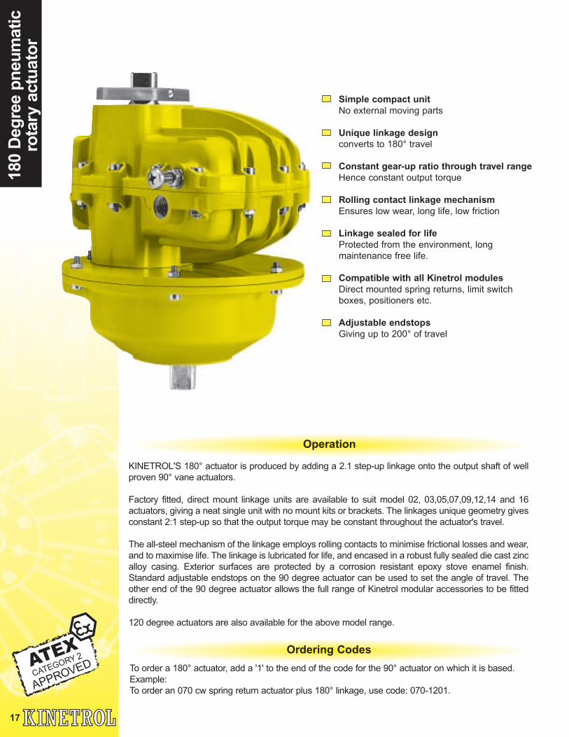
Simple compact unitNo external moving parts
Unique linkage designconverts to 180° travel
Constant gear-up ratio through travel rangeHence constant output torque
Rolling contact linkage mechanismEnsures low wear, long life, low friction
Linkage sealed for lifeProtected from the environment, long
maintenance free life.
Compatible with all Kinetrol modulesDirect mounted spring returns, limit switch
boxes, positioners etc.
Adjustable endstopsGiving up to 200° of travel
KINETROL'S 180° actuator is produced by adding a 2.1 step-up linkage onto the output shaft of well
proven 90° vane actuators.
Factory fitted, direct mount linkage units are available to suit model 02, 03,05,07,09,12,14 and 16
actuators, giving a neat single unit with no mount kits or brackets. The linkages unique geometry gives
constant 2:1 step-up so that the output torque may be constant throughout the actuator's travel.
The all-steel mechanism of the linkage employs rolling contacts to minimise frictional losses and wear,
and to maximise life. The linkage is lubricated for life, and encased in a robust fully sealed die cast zinc
alloy casing. Exterior surfaces are protected by a corrosion resistant epoxy stove enamel finish.
Standard adjustable endstops on the 90 degree actuator can be used to set the angle of travel. The
other end of the 90 degree actuator allows the full range of Kinetrol modular accessories to be fitted
directly.
120 degree actuators are also available for the above model range.
Operation
Ordering Codes
To order a 180° actuator, add a '1' to the end of the code for the 90° actuator on which it is based.
Example:
To order an 070 cw spring return actuator plus 180° linkage, use code: 070-1201.
180
Deg
ree
pn
eum
atic
rota
ry a
ctu
ato
r

18
180 Deg
ree pn
eum
aticro
tary actuato
rØK
AB
C
G x S longOutput square is shown at limit of travel (orientation is offset 45° to actuator shaft
N holes x T thread x D Deep x PCDMounting holes are aligned with actuator interface
Metric Units
English Units
N.B. Weights are inclusive of actuator and 180 degree
assembly
Actuator Model 1.4 2.0 2.8 3.5 4.1 4.8 5.5 6.2 6.9
02-1001 0.6 1.1 1.6 2.2 2.7 3.2 3.7 4.2 4.8
03-1001 1.3 2.4 3.5 4.6 5.6 6.7 7.8 8.8 10.0
05-1001 3.2 5.2 7.2 9.3 11.3 13.6 15.6 17.8 19.9
07-1001 7.9 12.6 17.6 22. 27.6 33.0 38.4 43.2 48.8
09-1001 16.3 20.0 37.1 47.6 58.0 69.2 80.4 91.2 103.0
12-1001 37.5 60.8 84.4 108.0 131.0 156.0 181.0 202.0 226.0
14-1001 97.2 151.0 206.0 262.0 316.0 375.0 434.0 488.0 542.0
16-1001 235.0 357.0 479.1 605.7 727.7 849.8 976.3 1098.4 1220.4
Pressure (bar)
Actuator Model 20 30 40 50 60 70 80 90 100
02-1001 5.6 10 14 19 24 28 33 37 42
03-1001 12 21 31 40 50 59 69 78 88
05-1001 28 46 64 82 100 120 138 157 176
07-1001 70 112 156 200 244 292 340 384 432
09-1001 144 236 328 420 512 612 712 808 912
12-1001 332 540 748 960 1160 1376 1588 1792 2000
14-1001 860 1340 1820 2320 2800 3320 3840 4320 4800
16-1001 2080 3160 4240 5360 6440 520 8640 9720 10800
Pressure (psi)
Actuator Model Position of air 3.5 4.0 4.5 5.0 5.5
OR spring stroke Pressure Setting (bar)
02-1201 Start 1.1 1.3 1.4 1.6 1.8
Finish 0.5 0.7 0.9 1.2 1.4
03-1201 Start 3.3 3.7 4.0 4.3 4.9
Finish 1.0 1.5 1.9 2.2 2.8
05-1201 Start 4.9 5.5 6.2 7.0 7.9
Finish 3.2 4.0 4.9 5.8 6.7
07-1201 Start 11.6 13.5 15.5 17.4 19.3
Finish 7.5 9.5 11.6 13.8 16.1
09-1201 Start 23.2 27.4 31.1 35.3 39.5
Finish 19.1 23.2 27.0 31.4 35.6
12-1201 Start 55.1 64.8 75.6 81.1 90.4
Finish 42.2 52.0 60.0 68.9 77.5
14-1201-4900 Start 135.0 156.0 178.0 195.0 201.0
Finish 109.0 131.0 148.0 164.0 170.0
16-1201 Start 346.8 391.0 426.0 465.0 504.3
Finish 181.4 237.0 282.0 332.0 381.9
Actuator Model Position of air 50 60 70 80
OR spring stroke Pressure Setting (psi)
02-1201 Start 10.3 12.2 14.1 16.0
Finish 4.6 6.8 9.5 12.5
03-1201 Start 29.6 33.4 37.2 43.7
Finish 8.7 13.7 19.0 24.7
05-1201 Start 44 51 61 70
Finish 28 38 49 59
07-1201 Start 103 126 146 171
Finish 67 92 116 143
09-1201 Start 205 251 300 351
Finish 169 215 266 315
12-1201 Start 486 595 693 802
Finish 374 479 585 688
14-1201-4900 Start 1200 1420 1670 1780
Finish 969 1200 1400 1500
16-1201 Start 3069 3534 3998 4463
Finish 1605 2197 2788 3380
Double Acting Torques / Metric Units Nm
Double Acting Torques / English Units lbf/ins
Spring Return Torques Metric Units Nm
Spring Return TorquesEnglish Units lbf/ins

19
Man
ual
Fai
l-S
afe
Sp
rin
g U
nit
sIf you want to operate a valve manually, but maintain the advantage of the
failsafe spring’s certainty of position when unattended, use this device.
Manual unit cannot be left in the wrong position
Reliable torque delivery for valve reseat
Fire fail-safe optionFor fail-safe manual operation of valves etc.
Clockwise or counter clockwise 90° spring action(02 reversible without the need for spring removal)
Weather proof sealed spring housing to protectfrom internal corrosion
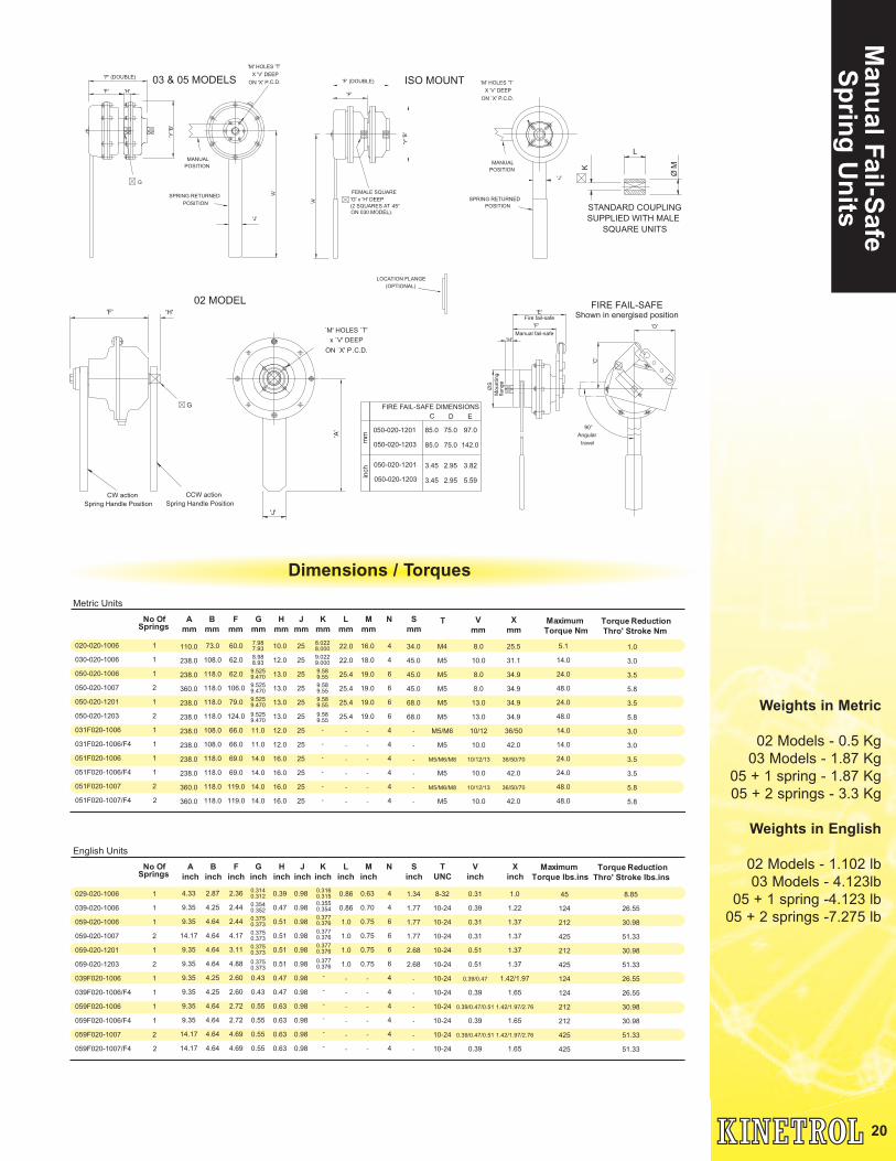
Application
Manual fail-safe spring units are available in
Kinetrol sizes 02, 03 and 05 with factory
adjusted torques from 1.4Nm to 45.5Nm.
Models 05, 09 and 12 fire fail-safe units
(maximum torque to 260Nm / 2300 lbf.ins) are
available - contact Kinetrol for details.
ISO / DIN Versions
The 03 & 05 single and double versions are
available with female ISO/DIN drive. 03
versions are available with F03, F05 and F04
flanges whilst 05 versions are available with
F03, F05, F07 and F04 flanges.
To order din flange units use code 031 or 051
at the start of the product code, and for F04
versions add F04 to the end of the order code.
Specification
Yield temperature °C 72 93
Max normal ambient temperature °C 42 63
Spring Case Die Cast zinc alloy with
epoxy paint finish
Shaft Stainless Steel
Lever Stainless Steel (03 & 05)
aluminium (02)
Optional Soldered type
fusible link (or equivalent) 2 options
Female spring Versions
Female ISO & Female ANSI direct mount
versions are available by replacing the dash ‘0-’
in the code with a ‘1F’. For example an ISO direct
mount manual failsafe is coded:
051F020-1006
Ordering Codes
To order a manual fail-safe spring unit, quote
model number, direction of spring (as per
technical data on page 4) followed by product
code.
Type Codes: 1006- single spring unit
1007- double spring unit
1201- single spring
fire fail-safe unit
1203- double spring
fire fail-safe unit
When ordering fire fail-safe units, please state
maximum torque required (at or below
maximum shown in table) and if appropriate
fusible link yield.
Example: for an 05 model, ISO threads, single
spring clockwise, 15Nm maximum torque, 72°
fusible link, the code would be:
050-020-1201-15Nm-72°C
20
Man
ual Fail-S
afe S
prin
g U
nits
'M' HOLES 'T'
ON 'X' P.C.D.
X 'V' DEEP
'Y''B
'
'F'
'F' (DOUBLE)
'H'
'A'
G
POSITION
MANUAL
POSITION
SPRING RETURNED
'J'
`M' HOLES `T'
ON `X' P.C.D.
x `V' DEEP
Spring Handle Position
CW action CCW action
Spring Handle Position
'A'
'J'
'F' 'H'
G
ON 030 MODEL).
SPRING RETURNED
'J'
Ø'P
'('R
')
'Z'('R')
LOCATION FLANGE
(OPTIONAL)
X 'V' DEEP
ON `X' P.C.D.
'M' HOLES 'T'
(2 SQUARES AT 45° POSITION
MANUAL
POSITION
'F' (DOUBLE)
'Y''B
'
'G' x 'H' DEEP
FEMALE SQUARE
'F'
'A'
Mo
un
tin
g
ØS
'F'
'E'
'C'
Manual fail-safe
Fire fail-safe
fla
ng
e
Angular
90°
travel
'D'
STANDARD COUPLING
SUPPLIED WITH MALE
SQUARE UNITS
L
ØMK
ISO MOUNT03 & 05 MODELS
02 MODELFIRE FAIL-SAFE
Shown in energised position
'H'
FIRE FAIL-SAFE DIMENSIONS
050-020-1201
C D E
050-020-1203
050-020-1201
050-020-1203
mm
inch
85.0 75.0 97.0
85.0 75.0 142.0
3.45 2.95 3.82
3.45 2.95 5.59
Metric Units
No Of A
mm
B
mm
F
mm
G
mm
H
mm
J
mm
K
mm
L
mm
M
mm
N S
mm
T V
mm
X
mm
Maximum
Torque Nm
Torque Reduction
Thro' Stroke Nm Springs
020-020-1006 1
030-020-1006 1
050-020-1006 1
050-020-1007 2
050-020-1201 1
050-020-1203 2
031F020-1006 1
031F020-1006/F4 1
051F020-1006 1
051F020-1006/F4 1
051F020-1007 2
051F020-1007/F4 2
110.0
238.0
238.0
360.0
238.0
238.0
238.0
238.0
238.0
238.0
360.0
360.0
73.0
108.0
118.0
118.0
118.0
118.0
108.0
108.0
118.0
118.0
118.0
118.0
60.0
62.0
62.0
106.0
79.0
124.0
66.0
66.0
69.0
69.0
119.0
119.0
7.98
7.93
8.98
8.93
9.525
9.470
9.525
9.470
9.525
9.470
9.525
9.470
11.0
11.0
14.0
14.0
14.0
14.0
10.0
12.0
13.0
13.0
13.0
13.0
12.0
12.0
16.0
16.0
16.0
16.0
25
25
25
25
25
25
25
25
25
25
25
25
8.022
8.000
9.022
9.000
9.58
9.55
9.58
9.55
9.58
9.55
9.58
9.55
-
-
-
-
-
-
22.0
22.0
25.4
25.4
25.4
25.4
-
-
-
-
-
-
16.0
18.0
19.0
19.0
19.0
19.0
-
-
-
-
-
-
4
4
6
6
6
6
4
4
4
4
4
4
34.0
45.0
45.0
45.0
68.0
68.0
-
-
-
-
-
-
M4
M5
M5
M5
M5
M5
M5/M6
M5
M5/M6/M8
M5
M5/M6/M8
M5
8.0
10.0
8.0
8.0
13.0
13.0
10/12
10.0
10/12/13
10.0
10/12/13
10.0
25.5
31.1
34.9
34.9
34.9
34.9
36/50
42.0
36/50/70
42.0
36/50/70
42.0
5.1
14.0
24.0
48.0
24.0
48.0
14.0
14.0
24.0
24.0
48.0
48.0
1.0
3.0
3.5
5.8
3.5
5.8
3.0
3.0
3.5
3.5
5.8
5.8
English Units
No Of A
inch
B
inch
F
inch
G
inch
H
inch
J
inch
K
inch
L
inch
M
inch
N S
inch
T
UNC
V
inch
X
inch
Maximum
Torque lbs.ins
Torque Reduction
Thro' Stroke lbs.ins Springs
029-020-1006 1
039-020-1006 1
059-020-1006 1
059-020-1007 2
059-020-1201 1
059-020-1203 2
039F020-1006 1
039F020-1006/F4 1
059F020-1006 1
059F020-1006/F4 1
059F020-1007 2
059F020-1007/F4 2
4.33
9.35
9.35
14.17
9.35
9.35
9.35
9.35
9.35
9.35
14.17
14.17
2.87
4.25
4.64
4.64
4.64
4.64
4.25
4.25
4.64
4.64
4.64
4.64
2.36
2.44
2.44
4.17
3.11
4.88
2.60
2.60
2.72
2.72
4.69
4.69
0.314
0.312
0.354
0.352
0.375
0.373
0.375
0.373
0.375
0.373
0.375
0.373
0.43
0.43
0.55
0.55
0.55
0.55
0.39
0.47
0.51
0.51
0.51
0.51
0.47
0.47
0.63
0.63
0.63
0.63
0.98
0.98
0.98
0.98
0.98
0.98
0.98
0.98
0.98
0.98
0.98
0.98
0.316
0.315
0.355
0.354
0.377
0.376
0.377
0.376
0.377
0.376
0.377
0.376
-
-
-
-
-
-
0.86
0.86
1.0
1.0
1.0
1.0
-
-
-
-
-
-
0.63
0.70
0.75
0.75
0.75
0.75
-
-
-
-
-
-
4
4
6
6
6
6
4
4
4
4
4
4
1.34
1.77
1.77
1.77
2.68
2.68
-
-
-
-
-
-
8-32
10-24
10-24
10-24
10-24
10-24
10-24
10-24
10-24
10-24
10-24
10-24
0.31
0.39
0.31
0.31
0.51
0.51
0.39/0.47
0.39
0.39/0.47/0.51
0.39
0.39/0.47/0.51
0.39
1.0
1.22
1.37
1.37
1.37
1.37
1.42/1.97
1.65
1.42/1.97/2.76
1.65
1.42/1.97/2.76
1.65
45
124
212
425
212
425
124
124
212
212
425
425
8.85
26.55
30.98
51.33
30.98
51.33
26.55
26.55
30.98
30.98
51.33
51.33
Dimensions / Torques
Weights in Metric
02 Models - 0.5 Kg
03 Models - 1.87 Kg
05 + 1 spring - 1.87 Kg
05 + 2 springs - 3.3 Kg
Weights in English
02 Models - 1.102 lb
03 Models - 4.123lb
05 + 1 spring -4.123 lb
05 + 2 springs -7.275 lb

21
Gea
red
Man
ual
Ove
rrid
esKinetrol de-clutchable geared overrides are
available for models 05, 07, 09, 10, 12, 14 and
16, rated for the same torques as the actuators
and fitted between the actuator and the load.
The standard unit is supplied with the right hand
handwheel option (see drawing below),
whereby when the handwheel is moved in a
clockwise direction the actuator moves in a
counter clockwise direction. A left hand
handwheel option is also available.
Dimensions
4 Mounting holes Mthread X N deep X PCD
Clutch disengaged forpneumatic operation
RH handwheel
L (except for model 10which has a femaleL X 28 (1.1") deep)
N.B. Drawing is not representative of model 16 Gearbox. For full details contact Kinetrol
A
B
S
E
F
D
KLeft hand handwheeloption
De-clutch lever switchavailable
Corrosion resistant -fully sealed to IP65
Metric Units
Actuator A B D E F K L M N PCD S W t
Model (ISO) mm mm mm mm mm mm mm mm mm mm kgs
05 300 67.8 13 170 103 127 9.5 M5 12 34.9 208 9.18
07 300 67.8 20 192 92 127 16.0 M8 16 50.9 208 11.20
09 300 67.8 26 218 92 127 19.0 M10 20 65.0 208 14.44
10 300 67.8 - 267 92 127 22.0 M10 20 102.0 208 17.50
12 300 67.8 31 248 92 127 25.0 M12 25 77.8 208 20.40
14 615 67.8 38 292 92 127 28.6 M16 28 98.8 270 32.06
16 610 132.0 55 448 174 194 41.0 M16 28 200.0 276 69.80
English Units
Actuator A B D E F K L M N PCD S W t
Model (ANSI) Inch Inch Inch Inch Inch Inch Inch UNC Inch Inch Inch lbs
05 11.81 2.67 0.51 6.69 4.06 5.0 0.375 10-24 0.47 1.375 8.19 20.2
07 11.81 2.67 0.79 7.56 3.62 5.0 0.630 0.63 2.000 8.19 24.7
09 11.81 2.67 1.02 8.58 3.62 5.0 0.748 0.79 2.560 8.19 31.8
10 11.81 2.67 - 10.51 3.62 5.0 0.866 0.79 4.016 8.19 38.5
12 11.81 2.67 1.22 9.76 3.62 5.0 0.984 0.98 3.060 8.19 44.9
14 24.20 2.67 1.50 11.50 3.62 5.0 1.125 1.10 3.890 10.63 70.5
16 24.00 5.20 2.17 17.64 6.85 7.64 1.614 1.10 7.874 10.87 154.0
5/16
-18
3/8 -16
3/8 -16
1/2 -13
5/8 -11
5/8 -11
Ordering Codes
Models 05 to 16:(Standard right hand handwheel)
Example for an 07 model:
070 K/Box (ISO Version)
079 K/Box (ANSI Version)
Models 05 to 16:(Left hand handwheel)
Example for an 07 model:
070 K/Box LH (ISO Version)
079 K/Box LH (ANSI Version)

22
ISO
adap
tor
Low cost direct mount flange and coupling for
mounting to valves with ISO 5211 drive
interfaces, available for actuator sizes 03 to 09
Mounting directly to standard Kinetrol double
acting actuator there by reducing stocking
requirements
Multiple mounting hole sets in one part
UK and US patents. The novel design allows
mounting screws to face in either direction.
Valve flanges with tapped holes can easily be
interfaced for the first time
Robust epoxy coated zinc alloy adaptor with
no threads for maximum corrosion resistance.
Female drive bi-square coupling is retained by
adaptor and made from zinc plated steel.
(Other materials available on request)
FEMALE
BI-SQUARE
G x E DEEP
(COUPLING
RETAINED)
X
W
YVENT
GROOVES
J
H
HEXAGON
RECESSES
International Patents
FIXED

23
Mo
del
OM
O(m
inia
ture
)
Specification
Output Torque
8.0 lbf.ins/0.9 Nm
at 100 psi/7bar
Angle of Travel(Adjustable)
80° - 100°
(Restricted travel
versions available)
Displaced Volume
0.15in3
/ 2.4cm3
Finish
Epoxy stove enamel
Weight
0.26 lb/0.12 kg
For further information
see General Specification
on page 49.
2 M5 Air Ports
Staggered
5.9
90
5.9
78
5.00
3610
8
Actual Size
Code identification see page 38
Torque outputs see pages 47/48
2 M5 Air Ports
staggered
5.9
90
5.9
78
8
10 36
5.00
Options
4 M3 x 5 deep mount holes
on 16.0 PCD
30.7
32
12.5

24
Mo
del 01
Specification
Output Torque
58lbf.ins/6.7Nm
at 100 psi/7bar
Angle of Travel(Adjustable)
See Drawing
(Restricted travel
versions available)
Displaced Volume
0.91in3
/ 15cm3
Finish
Epoxy stove enamel
Weight
See Drawing
For further information
see General Specification
on page 49.
English Dimensions see page 42
Fail safe spring return units - clockwise or counterclockwise
Code identification see page 38
Torque outputs see page 47/48
Size details of options see page 42
Options
57.3
14.4
71.4
6.3
5
6.3
3
63.5
7.6
31.7
5
4 Aux. Mount HolesM4 X 6 deep on 19.0 PCD
Air Ports / Mount HolesModel Air Ports Mount Holes
010-100A G1/8” M4 x 6 deep x 19.0 PCD
019-100A 1/8” NPT 8-32 UNC x 0.25”
deep on 1.00” PCD
4 Mount Holes each side
details below
4 Aux. Mount holes
details below
4 mount holes
details below
12.7
4.8
0
4.7
8
9.5
3
Standard Coupling
(supplied with both actuators
weight 0.22 lbs/0.1kg)
71.4
57
.3
14
.4
63.5
7.6
31.5
71.4
50.8 2 air ports
thread details below
4.75
4.70
Shown at limit of
travel
6.3
3
6.3
5
14.8
60.5
8.4
25.76 to radius
7.2
12.538.57
38.57 12.5
15.87.2
6 to radius
6.3
3
6.3
5
4.75
4.702 air ports staggered
details below
ACTUATOR 010-100AAngle of travel: 78° - 100°
Weight 0.33 lb/0.15 kg
ACTUATOR 010-100Angle of travel: 90°
Weight 0.40 lb/0.18 kg
010-100 010-100A

25
Mo
del
02
Specification
Output Torque
106.2lbf.ins/12.1Nm
at 100 psi/7bar
Angle of Travel(Adjustable)
80° - 100°
(Restricted travel
versions available)
Displaced Volume
1.89in3
/ 31cm3
Finish
Epoxy stove enamel
Weight
0.97 lb / 0.44 kg
For further information
see General Specification
on page 49
English Dimensions see page 42
Fail safe spring return units - clockwise orcounter clockwise
180° model
Code identification see page 38
Torque outputs see page 47/48
Size details of options see page 42
Options
18
Air Ports / Mount HolesModel Air Ports Mount Holes
020-100 G1/8” M4 x 8 deep x 25.5 PCD
028-100 G1/8” M4 x 8 deep x 25.5 PCD
029-100 1/8” NPT UNC 8-32 x 0.31”
deep on 1.00” PCD
10 10
8.5 to radius7.7
16
8.0
22
8.0
00
20.0
2 Air ports staggered
thread details below
5010 10
7.78.5 to radius
7.98
7.93
Shown at limit
of travel
Standard Coupling
(supplied actuator
weight 0.04 lbs/0.02kg)
93
18.0
24.1
76
18
4 mount holes
each side details below

26
Mo
del 03
Specification
Output Torque
220lbf.ins/25Nm
at 100 psi/7bar
Angle of Travel(Adjustable)
80° - 100°
(Restricted travel
versions available)
Displaced Volume
3.66in3
/ 60cm3
Finish
Epoxy stove enamel
Weight
1.53 lb/0.70 kg
(excluding coupling)
For further information see
General Specification on
page 49
English Dimensions see page 42
Options
Fail safe spring return units - clockwiseor counter clockwise
Limit switch boxes for open/closeindication - various switches for allhazardous areas
Integral solenoid valve
180° model
Female drive and mounting details to DIN3337 and ISO 5211
ISO adaptor
Code identification see page 38
Torque outputs see page 47/48
Size details of options see page 42
33
.6
Air Ports / Mount HolesModel Air Ports Mount Holes
030-100 G1/8” M5 x 10 deep x 31.1 PCD
038-100 G1/8” M5 x 10 deep x 31.1 PCD
039-100 1/8” NPT 10-24 UNC x 0.39”
deep on 1.23” PCD
22
18
9.0
22
9.0
00
12 1260.0
16
33
.6
8
10.5 to radius
2 Air ports staggered
thread details below
8.98
8.93
Shown at limit
of travel
Standard Coupling
(supplied actuator
weight 0.07 lbs/0.03kg)
22.0
4 mount holes
each side details below
113
91.4
22.0
5
MA
X 22.0
28

9.5
8
9.5
5
25.4
19
Standard Coupling
(supplied actuator
weight 0.09 lbs/0.04kg)
13 1367
16
8
11 to radius
45
2 Air ports staggered
thread details below
9.53
9.47
Shown at limit
of travel
136
5
MA
X
33.6
112
6 mount holes
each side details below
Air Ports / Mount HolesModel Air Ports Mount Holes
050-100 G1/8” M5 x 10 deep x 34.9 PCD
058-100 G1/8” M5 x 10 deep x 34.9 PCD
059-100 1/8” NPT UNC 10-24 x 0.39”
deep on 1.375” PCD
27
Mo
del
05
Specification
Output Torque
440lbf.ins/50Nm
at 100 psi/7bar
Angle of Travel(Adjustable)
84° - 100°
(Restricted travel
versions available)
Displaced Volume
6.9in3
/ 113 cm3
Finish
Epoxy stove enamel
Weight
2.73 lb / 1.24 kg
For further information
see General Specification
on page 49
English Dimensions see page 42
Fail safe spring return units - clockwiseor counter clockwise
Limit switch boxes for open/closeindication various switches for allhazardous areas
AP Pneumatic positioner - full range ofoptions see pages 11 & 12
EL electropneumatic positioner - fullrange of options see pages 15 & 16
Integral solenoid valve
3 stop positioner
Options
Clear cone position monitor
180° model
Female drive and mounting details toDIN 3337 and ISO 5211
ISO adaptor
Geared manual override
Code identification see page 38
Torque outputs see page 47/48
Size details of options see page 42

28
Mo
del 07
English Dimensions see page 42
Options
Fail safe spring return units - clockwiseor counter clockwise
Limit switch boxes for open/closeindication various switches for allhazardous areas
AP Pneumatic positioner - full range ofoptions see pages 11 & 12
EL electropneumatic positioner - fullrange of options see pages 15 & 16
Integral solenoid valve
3 stop positioner
Clear cone position monitor
180° model
Female drive and mounting details toDIN 3337 and ISO 5211
ISO adaptor
3/8” ports
Geared manual override
Code identification see page 38
Torque outputs see page 47/48
Size details of options see page 42
64
Air Ports / Mount HolesModel Air Ports Mount Holes
050-100 G1/4” M8 x 16 deep x 50.9 PCD
058-100 G1/4” M8 x 16 deep x 50.9 PCD
059-100 1/4” NPT UNC 5/16 -18x 0.63”
deep on 2.00” PCD
15.98
15.93
Shown at limit
of travel
2 Air ports staggered
thread details below
4 mount holes
each side details below
64
178
146
MA
X
36
36
43.4
Standard Coupling
(supplied actuator
weight 0.37 lbs/0.17kg)
16
.02
7
16
.00
0
20 20100
20
10
18 to radius
40
32
Specification
Output Torque
1080lbf.ins/124Nm
at 100 psi/7bar
Angle of Travel(Adjustable)
80° - 100°
(Restricted travel
versions available)
Displaced Volume
18.3in3
/ 300 cm3
Finish
Epoxy stove enamel
Weight
6.91 lb / 3.13 kg
For further information
see General Specification
on page 49
5

29
Mo
del
08
English Dimensions see page 42
Fail safe spring return units - clockwise orcounter clockwise
Limit switch boxes for open/close indication - various switches for all hazardous areas
AP Pneumatic positioner - full range ofoptions see pages 11 & 12
EL electropneumatic positioner - full range ofoptions see pages 15 & 16
Code identification see page 38
Torque outputs see page 47/48
Size details of options see page 42
Options
Air Ports / Mount HolesModel Air Ports Mount Holes
080-100 G1/4” M8 x 16 deep x 50.9 PCD
088-100 G1/4” M8 x 16 deep x 50.9 PCD
089-100 1/4” NPT UNC 5/16-18 x 0.63”
deep on 2.00” PCD
155
41.4
17928.5
39
28
.5
Standard Coupling
(supplied actuator
weight 0.031lbs/0.14kg)
14
.36
14
.34
2 Air ports staggered
thread details below
14.30
14.25
Shown at limit
of travel
19 1999
17 to radius
9.5
19
63
.5
6 mount holes
each side details below
Specification
Output Torque
1500lbf.ins/173Nm
at 100 psi/7bar
Angle of Travel(Adjustable)
72° - 93°
(Restricted travel
versions available)
Displaced Volume
23.9in3
/ 392 cm3
Finish
Epoxy stove enamel
Weight
6.85 lb / 3.11 kg
For further information
see General Specification
on page 49.

30
Mo
del 09
English Dimensions see page 42
Options
Fail safe spring return units - clockwiseor counter clockwise
Limit switch boxes for open/closeindication various switches for allhazardous areas
AP Pneumatic positioner - full range ofoptions see pages 11 & 12
EL electropneumatic positioner - fullrange of options see pages 15 & 16
Integral solenoid valve
3 stop positioner
Clear cone position monitor
180° model
Female drive and mounting details toDIN 3337 and ISO 5211
ISO adaptor
3/8” ports
Geared manual override
Code identification see page 38
Torque outputs see page 47/48
Size details of options see page 42
38
20
Air Ports / Mount HolesModel Air Ports Mount Holes
090-100 G1/4” M10 x 20 deep x 65.5 PCD
098-100 G1/4” M10 x 20 deep x 65.5 PCD
099-100 1/4” NPT UNC 3/8-16 x 0.79”
deep on 2.56” PCD
38
19
.00
33
19
.00
00
50
Standard Coupling
(supplied actuator
weight 0.6 lbs/0.3kg)
26126
26
23.5 to radius20
10
84
2 Air ports staggered
thread details below
18.98
18.93
Shown at limit
of travel
46.0
187
5
MA
X
227
46.0
54.7
4 mount holes
each side details below
Specification
Output Torque
2280lbf.ins/261Nm
at 100 psi/7bar
Angle of Travel(Adjustable)
80° - 100°
(Restricted travel
versions available)
Displaced Volume
39.3in3
/ 644cm3
Finish
Epoxy stove enamel
Weight
13.82 lb/6.24 kg
(excluding coupling)
For further information
see General
Specification on page 49

Air Ports / Mount HolesModel Air Ports Mount Holes
101-100 G1/4” M10 x 16 deep x 102.0 PCD
108-100 G1/4” M10 x 16 deep x 102.0 PCD
109-100 1/4” NPT UNC 3/8-16 x 0.79”
deep on 4.02” PCD
Female drive and mounting details to DIN 3337
and ISO 5211 as standard
10
23.5 to radius
Female SquareDIN (F10) 22 x 24
72.125
4 mount holes
each side details below
230
188.5
5
MA
X
71.125
58
21.98
21.93
Shown at limit
of travel
2 Air ports staggered
thread details below
25.5175
210
3
23.5 to radius Female Square
DIN (F10) 22 x 24 deep
70
31
Mo
del
10
English Dimensions see page 42
Options
Fail safe spring return units - clockwiseor counter clockwise
Limit switch boxes for open/closeindication various switches for allhazardous areas
AP Pneumatic positioner - full range ofoptions see pages 11 & 12
EL electropneumatic positioner - fullrange of options see pages 15 & 16
Integral solenoid valve
3 stop positioner
Clear cone position monitor
Geared manual override
Code identification see page 38
Torque outputs see page 47/48
Size details of options see page 42
Specification
Output Torque
3625 lbf.ins/416 Nm
at 100 psi/7bar
Angle of Travel(Adjustable)
78° - 100°
(Restricted travel
versions available)
Displaced Volume
62.5in3
/ 1025cm3
Finish
Epoxy stove enamel
Weight
21.2 lb / 9.6 kg
For further information
see General Specification
on page 49.

32
Mo
del 12
English Dimensions see page 42
Options
Fail safe spring return units - clockwiseor counter clockwise
Limit switch boxes for open/closeindication various switches for allhazardous areas
AP Pneumatic positioner - full range ofoptions see pages 11 & 12
EL electropneumatic positioner - fullrange of options see pages 15 & 16
Integral solenoid valve
3 stop positioner
Clear cone position monitor
180° model
Female drive and mounting details to DIN3337 and ISO 5211
Geared manual override
Code identification see page 38
Torque outputs see page 47/48
Size details of options see page 42
Air Ports / Mount HolesModel Air Ports Mount Holes
120-100 G3/8” M12 x 20 deep x 65.5 PCD
128-100 G3/8” M12 x 20 deep x 65.5 PCD
129-100 3/8” NPT UNC 1/2-13 x 0.98”
deep on 3.06” PCD
4 mount holes
each side details
below
294
239
55.0
55.0
5
MA
X
68
10
0
2 Air ports staggered
thread details below
24.98
24.93
Shown at limit
of travel
56
25
.06
25
.00
50
Standard Coupling
(supplied actuator
weight 1.3lbs/0.6kg)
28
3115631
27 to radius
14
Specification
Output Torque
5000 lbf.ins/575 Nm
at 100 psi/7bar
Angle of Travel(Adjustable)
80° - 102°
(Restricted travel
versions available)
Displaced Volume
86in3
/ 1410cm3
Finish
Epoxy stove enamel
Weight
26.2 lb/11.9 kg
(excluding coupling)
For further information see
General Specification on
page 49

33
Mo
del
14
Specification
Output Torque
12000 lbf.ins/1375 Nm
at 100 psi/7bar
Angle of Travel(Adjustable)
80° - 100°
(Restricted travel
versions available)
Displaced Volume
201 in3
/ 3294 cm3
Finish
Epoxy stove enamel
Weight
44.5 lb / 23.1 kg
For further information
see General Specification
on page 49.
English Dimensions see page 42
Options
Fail safe spring return units - clockwiseor counter clockwise
Limit switch boxes for open/closeindication various switches for allhazardous areas
AP Pneumatic positioner - full range ofoptions see pages 11 & 12
EL electropneumatic positioner - fullrange of options see pages 15 & 16
Integral solenoid valve
3 stop positioner
Clear cone position monitor
180° model
Female drive and mounting details to DIN3337 and ISO 5211
Geared manual override
Code identification see page 38
Torque outputs see page 47/48
Size details of options see page 42
Air Ports / Mount HolesModel Air Ports Mount Holes
140-100 G1/2” M16 x 28 deep x 98.8 PCD
148-100 G1/2” M16 x 28 deep x 98.8 PCD
149-100 1/2” NPT UNC 5/8-11 x 0.1.12”
deep on 3.89” PCD
2 Air ports staggered
thread details below
28.58
28.53
Shown at limit
of travel
38 38
34 to radius
32
16
12
8
200
381
308
5
84
69.8
5
4 mount holes
each side details below
63.5
41
.08
41
.00
57
Standard Coupling
(supplied actuator
weight 1.5 lbs/0.7kg)

34
Mo
del 16
English Dimensions see page 42
Options
Fail safe spring return units - clockwiseor counter clockwise
Limit switch boxes for open/closeindication various switches for allhazardous areas
AP Pneumatic positioner - full range ofoptions see pages 11 & 12
EL electropneumatic positioner - fullrange of options see pages 15 & 16
180° model
Female drive and mounting details toDIN 3337 and ISO 5211
Geared manual override
Code identification see page 38
Torque outputs see page 47/48
Size details of options see page 42
R.24
4 mount holes
each side details below
Air Ports / Mount HolesModel Air Ports Mount Holes
160-100 G1/2” M24 x 38 deep x 152.7 PCD
168-100 G1/2” M24 x 38 deep x 152.7 PCD
169-100 1/2” NPT UNC 7/8-9 x 1.50”
deep on 6.012” PCD
425
525
108
125
108
90
49
41
.08
41
.00
58
.08
58
.00
85
55274
55
Standard Coupling
(supplied actuator
weight 5.3 lbs/0.03kg)
2 air ports staggered
details below
32
16
40.95
40.87
Shown at limit
of travel
17
5
49 to
radius
Auxiliary Mount Holes
4 Holes M5 x 8 Deep
2 Dowel Holes
20.00 x 40 deep
Specification
Output Torque
27000 lbf.ins/3100 Nm
at 100 psi/7bar
Angle of Travel(Adjustable)
80° - 100°
(Restricted travel
versions available)
Displaced Volume
465in3
/ 7630cm3
Finish
Epoxy stove enamel
Weight
82.5 lb/37.4 kg
(excluding coupling)
For further information
see General
Specification on page 49

35
Mo
del
18
Specification
Output Torque
60000 lbf.ins/6900 Nm
at 100 psi/7bar
Angle of Travel(Adjustable)
80° - 100°
(Restricted travel
versions available)
Displaced Volume
1047 in3
/ 17170 cm3
Finish
Epoxy stove enamel
Weight
157.4 lb / 71.4 kg
For further information
see General Specification
on page 49
English Dimensions see page 42
Options
Fail safe spring return units - clockwiseor counter clockwise
Limit switch boxes for open/closeindication various switches for all hazardousareas
AP Pneumatic positioner - full range ofoptions see pages 11 & 12
Air Ports / Mount HolesModel Air Ports Mount Holes
180-100 G3/4” M30 x 50 deep x 226.3 PCD
188-100 G3/4” M30 x 50 deep x 226.3 PCD
189-100 3/4” NPT UNC 11/8-7 x 2.01”
deep on 8.91” PCD
2 air ports staggered
details below
KI
E T R OL
18
N
36078 78
72 to
radius
28
6
52
26
56.95
56.85
Shown at limit
of travel
130
57
.1
57
.0
11
5
73
80
.08
80
.00
Standard Coupling
(supplied actuator
weight 13.7lbs/6.2kg)
160
162
554
160
680
R30
4 mount holes
each side details below
Auxiliary Mount Holes
4 Holes M5 x 8 Deep
2 Dowel Holes
25.00 x 50 deep
EL electropneumatic positioner - fullrange of options see pages 15 & 16
Code identification see page 38
Torque outputs see page 47/48
Size details of options see page 42
Standard Coupling
(supplied actuator
weight 34lbs/15.4kg)170
73
.17
73
.00
15
0
88
10
0.0
7
10
0.0
0
2 air ports staggered
details below
620
94 to
radius
28
6
72.95
72.85
Shown at limit
of travel
100
154
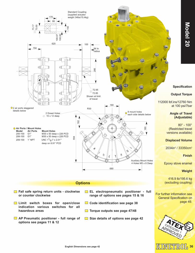
Air Ports / Mount HolesModel Air Ports Mount Holes200-100 G1” M30 x 50 deep x 226 PCD
208-100 G1” M30 x 50 deep x 226 PCD
209-100 1” NPT UNC 11/8-7 x 2.01””
deep on 8.91” PCD
160
162
554
R30
8 mount holes
each side details below
160
680
Auxiliary Mount Holes
4 Holes M5 x 8 Deep
2 Dowel Holes
10 x 12 deep
36
Mo
del 20
English Dimensions see page 42
Options
Fail safe spring return units - clockwiseor counter clockwise
Limit switch boxes for open/closeindication various switches for allhazardous areas
AP Pneumatic positioner - full range ofoptions see pages 11 & 12
EL electropneumatic positioner - fullrange of options see pages 15 & 16
Code identification see page 38
Torque outputs see page 47/48
Size details of options see page 42
Specification
Output Torque
112000 lbf.ins/12760 Nm
at 100 psi/7bar
Angle of Travel(Adjustable)
80° - 100°
(Restricted travel
versions available)
Displaced Volume
2034in3
/ 33350cm3
Finish
Epoxy stove enamel
Weight
416.9 lb/195.6 kg
(excluding coupling)
For further information see
General Specification on
page 49.

37
Mo
del
30
Specification
Output Torque
168000 lbf.ins/19140 Nm
at 100 psi/7bar
Angle of Travel(Adjustable)
80° - 100°
(Restricted travel
versions available)
Displaced Volume
3050 in3
/ 50025 cm3
Finish
Epoxy stove enamel
Weight
601.91 lb / 273 kg
For further information
see General Specification
on page 49.
English Dimensions see page 42
Fail safe spring return units - clockwiseor counter clockwise
Limit switch boxes for open/closeindication various switches for all hazardous areas
AP Pneumatic positioner - full range ofoptions see pages 11 & 12
Options
Air Ports / Mount HolesModel Air Ports Mount Holes300-100 G1” M30 x 50 deep x 226.3 PCD
308-100 G1” M30 x 50 deep x 226.3 PCD
309-100 1” NPT UNC 11/8-7 x 2.01”
deep on 8.91” PCD
170
73
.17
73
.00
15
0
88
160
17
4
56
6
692
R30
8 mount holes
each side details below
10
0.0
7
10
0.0
0
Standard Coupling
(supplied actuator
weight 34lbs/15.4kg)
2 air ports staggered
details below
286
880
94 to
radius
72.95
72.85
Shown at limit
of travel
100
154
2 Dowel Holes
10 x 12 deep
Auxiliary Mount Holes
4 Holes M5 x 8 Deep
EL electropneumatic positioner - fullrange of options see pages 15 & 16
Code identification see page 38
Torque outputs see page 47/48
Size details of options see page 42

Low Pressure Air Application ordering codes -see page 4
Femal Drive unit ordering codes -see page 5
Universal Limit Switch ordering codes -see pages 7/ 8
AP Positioner ordering codes -see pages 11 /1 2
EL Positioner ordering codes -see pages 15/16
3-stop positioner ordering codes -see page 14
180∞ actuator ordering codes -see pages 17/18
Maual failsafe unit ordering codes -see pages 19/20
Geared Manual Overrides ordering codes -see page 21
Damper Drive ordering codes -see pages 39/40
EXAMPLES
A: 050-100 Double Acting Actuator (ISO Threads) No optional supplementary ite m
B. 050-120M A + spring return (fail-safe CW) + clear cone monito r
C. 078-100 Double acting actuator with Pg cable entry thread
D. 059-100 Double acting actuator (ANSI threads)
E. 140-130-4900 140 Actuator (ISO threads) + spring return failsafe CCW (2 x 120 springs)
ACTUA TO R or
ACTUA TO R / POSITIONER
ASSEMBL Y
MODEL
SIZE / THREAD
CODE
SPRING RETURNS
OPTIONAL
SUPPLEMENT AR Y
CODE
010
to
200
018
to
208
019
to
209
031
to
161
032
to
142
033
to
143
034
to
144
IS O
Thread
standar d
Pg Cabl e
entry
Thread
standar d
ANSI
Thread
Standar d
DI N
Flange
standar d
(female drive )
DIN Flange
standar d
with NAMUR
Adaptor
DIN Flange
Actuator fo r
Positioner
Actuator onl y
for Postioner
ISO/DI N
Threads
037
to
147
Actuator
only fo r
Positioner
ANSI thread
0 No Actuto r
1 With A ctuator
2 Actuator & 3 Por t
Single Solenoi d
3 Actuator & 5 Por t
Single Solenoi d
NB Other Solenoid s
by descriptio n
9 Special Product
Specifications
- Contact Kinetro l
1
0 No Spring Retur n
2 Spring Return cw
3 Spring Return ccw
4 Spring Return to
centre
1006 Manual failsafe
spring unit (singl e
spring)
1007 Manual failsafe
spring unit (doubl e
spring)
1201 Fire failsafe sprin g
unit (05 size )
1202 Fire failsafe sprin g
unit (2 x 05 size )
1302 Discrete limit switch
unit (non latchable)
1305 Discrete limit switch
unit (latchable)
2100 High tempeature
Elastomer seal s
Abbreviations:
cw: Clockwise
ccw: Counter
(or anti)
Clockwise
1
Give Electrical Details.
(V olts & Hertz)
Optional Suffixes:
M: Clear cone
position monitor
N: NAMUR adaptor
S: Solenoid valve silencers
/ flow regulators
Z: Less coupling
035
to
145
ISO Thread
standard with
NAMUR
adaptor
036
to
146
ANSI Thread
standard with
NAMUR
adaptor
Please Note:
There has been a decline of Pg cable thread entry
requirements, if this is required with a NAMUR
adaptor order the unit in the normal way, along with
an SP638 with a comment "Fit items together".
ISO adaptor odering codes -see page 22
0
38
Actu
ator G
eneral
Ord
ering
Co
des
Kinetrol Actuators and Add-on control units

39
G3
Dam
per
Dri
ve
Kinetrol's rigorous quality
program is approved to ISO
9001:2000 and AS/EN 9100
ensuring that each unit is
manufactured to the highest
standards.
Certificate No. FM22163
Kinetrol Actuators, Springs
and Accessories are now
approved up to ATEX
Category 1.
For modulating or on/off control with failure mode options
Integral manual override
Suitable for new installations orreplacement of existing electric orpneumatic drives
Can result in lower energy costsresulting from accurate flow control
Reduced operating costs due to long maintenance-free life
Compact space saving design
Quick and easy installation and set up
US Patent No: US6,939,931 B1
*Listed weights exclude actuator
Purpose designed factory built and
tested drives for air/gas flow control
dampers on burner, heater, boiler
and turbine systems in power
plants, refineries and a wide range
of industrial applications.
Fully integrated packages with
patented mounting flange for easy
fitting to simple stands, can be used for
on/off or modulations control, double
acting or spring return, and with a full range
of integrated direct mount Kinetrol
accessories.
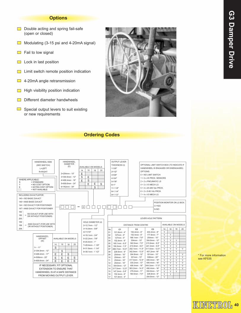
OPTIONAL LIMIT SWITCH BOX (TO INDICATE IF
HANDWHEEL IS ENGAGED OR DISENGAGED)
OPTIONS:
0 = NO LIMIT SWITCH
1 = 2 x i/S PROX. SENSORS
2 = 2 x PNEUMATIC LS
4 = 2 x V3 MECH LS
5 = 2 x 20-260 Vac PROX.
6 = 2 x 5-60 Vdc PROX.
7 = 4 x V3 MECH LS
POSITION MONITOR ON LS BOX:
C=YES
0=NO
HANDWHEEL SIDE
(SEE SKETCH)
L=LEFT
R=RIGHT
HOLE DIAMETER (d)
2=12.7mm - 1/2"
3=15.9mm - 5/8"
A=11/16"
4=19.1mm - 3/4"
5=22.2mm - 7/8"
6=25.4mm - 1"
7=28.6mm - 1 1/8"
8=31.8mm - 1 1/4"
9=38.1mm - 1 1/2"
OUTPUT LEVER
THICKNESS (t)
1=3/8"
2=1/2"
3=5/8"
4=3/4"
5=7/8"
6=1"
7=1 1/8"
8=1 1/4"
9=1 1/2"
D
AVAILABLE ON MODELS:
14 16 18 20
HANDWHEEL
OFFSET
(W)
1= - 11"
2=304.8mm - 12"
3=406.4mm - 17"
4=508mm - 20"
5=609.6mm - 24"
LEVER HOLE PATTERN
DISTANCE FROM CENTRE AVAILABLE ON MODELS
1614 18 20No.
01
02
03
04
05
06
07
08
09
10
11
12
13
14
15
16
17
C1
101.6mm - 4"
127mm - 5"
127mm - 5"
152.4mm - 6"
165.1mm - 6.5"
190.5mm - 7.5"
266.7mm - 10.5"
228.6mm - 9"
254mm - 10"
254mm - 10"
254mm - 10"
254mm - 10"
304.8mm - 12"
317.5mm - 12.5"
147.3mm - 5.8"
152.4mm - 6"
101.6mm - 4"
C2
152.4mm - 6"
152.4mm - 6"
198.1mm - 7.8"
254mm - 10"
190.5mm - 7.5"
215.9mm - 8.5"
292.1mm - 11.5"
342.9mm - 13.5"
304.8mm - 12"
301mm - 15"
317.5mm - 12.5"
330.2mm - 13"
406.4mm - 16"
363.2mm - 14.3"
279.4mm - 11"
190.5mm - 7.5"
-
C3
203.2mm - 8"
177.8mm - 7"
254mm - 10"
304.8mm - 12"
215.9mm - 8.5"
241.3mm - 9.5"
317.5mm - 12.5"
457.2mm -18"
301mm - 15"
508mm - 20"
406.4mm - 16"
406.4mm - 16"
444.5mm - 17.5"
406.4mm - 16"
304.8mm - 12"
228.6mm - 9"
304.8mm - 12"
AVAILABLE ON MODELS:
14 16 18 20
HANDWHEEL
DIAMETER
(D)
2=254mm - 10"
3=304.8mm - 12"
4=406.4mm - 16"
5=609.6mm - 24"
6=762mm - 30"
E
E
S E
S
E E S
S
S
S
S
S
E
E
E
E
E
E
E
E E
IF NECESSARY, FIT OPTIONAL
EXTENSION TO ENSURE THAT
HANDWHEEL IS AT A SAFE DISTANCE
FROM MOVING OUTPUT LEVER.
INCLUDING D/A ACTUATOR:
140 = ISO BASIC D/A ACT
149 = ANSI BASIC D/A ACT
144 = ISO D/A ACT FOR POSITIONER
147 = ANSI D/A ACT FOR POSITIONER
160
180
200
169
189
209
ISO D/A ACT (FOR USE WITH
OR WITHOUT POSITIONER)=
ANSI D/A ACT (FOR USE WITH
OR WITHOUT POSITIONER)=
Y
Y
Y
Y
Y
Y
Y
Y
Y
Y
Y
Y
Y
Y
Y
Y
Y
Y
Y
Y
Y
Y
Y
Y
Y
Y
Y
Y
Y
Y
Y
Y
Y
Y
Y
Y
Y
Y
Y
Y
Y
Y
Y
Y
Y
Y
Y
Y
Y
Y
Y
WHERE APPLICABLE:
S = STANDARD
Y = NO COST OPTION
E = EXTRA COST OPTION
= NOT AVAILABLE
40
G3 D
amp
er Drive
Options
Double acting and spring fail-safe
(open or closed)
Modulating (3-15 psi and 4-20mA signal)
Fail to low signal
Lock in last position
Limit switch remote position indication
4-20mA angle retransmission
High visibility position indication
Different diameter handwheels
Special output levers to suit existing
or new requirements
Ordering Codes
* For more information
see KF535

41
Inte
rfac
e O
ptio
ns
&
Val
ve M
ou
ntin
g S
ervi
ceKinetrol Interfacing Options
Kinetrol is in a continually changing environment when it comes to interfacing options between its
quarter-turn actuators, control units and other auxhilliary equipment and do offer a range of
products and adaptors that conform to most industry standards.
The patended ‘ISO adaptor’ is available now and is available for Kinetrol actuator models 03-09.
It provides a robust mounting option between Kinetrol’s actuators and valves that conform to the
ISO 5211 standard.
As well as the ISO adaptor, various actuator models are now designed to provide mounting
options using the VDI/VDE 3847 standard without compromising the actuators performance or
robust casing.
The third standard interfacing option that Kinetrol have designed for is the Namur
reccomendation NE 014. Shafts on many the the control modules and actuator models have been
deisigned to fit Namur standard products and uphold the integrity of the joints between ‘add on’
accessories, actuators and valves.
Direct mount products are also available including female drive spring units, manual fail-safe
handles, positioners and our universal limit switch box.
For solenoid mounting, Kinetrol have manufactured the Namur interface adaptor to cut out all
external piping, allowing the air to port directly to the actuator body.
Kinetrol now has well over 40 years experience in the industry and is well renowned for its
build quality. Thousands of mount kit designs are available, and new mountings can be
designed to meet specific customer requirements at any time.
We can source a wide range of Ball, Butterfly and Plug valves
from across the world and then design the package that is right
for you, using our robust 90° pneumatic actuator and any of our
modular ‘add on’ control units.
We can now provide you with full ATEX explosion proof products as
well as an AS Interface option and a range of new and improved
control modules.
Our build quality and rigorous in-house quality control and testing
ensures that you will be supplied with an unbeatable product upon
arrival at your site.
For questions regarding our valve mounting service please contact
Kinetrol.
Kinetrol’s Valve Mounting Service

42
Assem
bly Dim
ensionsN Number of holes T thread x D deep x PCD or R
A
B
C
R
R
L
G
ØK
S H S
ØF
Air ports P
(staggered)
Shown at limit
of travel
4 Mounting holes
W thread x Y deep
x PCDM M H
EM
J
ØV
ØU
A
mm
B
mm
C
mm
G
mm
H
mm
F
mm
S
mm
N
No.
T
ISO
D
mm
R
mm
P
ISO
L
mm
Wt
kg
OMO 32.0 30.7 12.5 36.0 10.0 4 M3 5.0 16.0 M5 0.12
01 71.4 60.5 14.8 4.8 37.0 9.5 12.7 0.28
01A 71.4 57.3 14.4 4.8 38.5 4 M4 6.0 19.0 9.5 12.7 0.25
02 93.0 76.0 24.1 8.0 50.0 10.0 4 M4 8.0 18.0 25.5 16.0 20.0 0.44
03 113.0 91.4 28.0 9.0 60.0 33.6 12.0 4 M5 10.0 22.0 31.1 18.0 22.0 0.73
05 136.0 112.0 33.6 9.5 67.0 45.0 13.0 6 M5 10.0 34.9 19.0 25.4 1.28
07 178.0 146.0 43.4 16.0 100.0 64.0 20.0 4 M8 16.0 36.0 50.9 32.0 40.0 3.30
08 179.0 155.0 41.4 14.3 99.0 63.5 19.0 6 M8 16.0 50.8 28.5 39.0 3.25
09 227.0 187.0 54.7 19.0 126.0 84.0 26.0 4 M10 20.0 46.0 65.0 38.0 50.0 6.54
10 * 230.0 188.5 58.0 22.0 175.0 25.5 4 M10 16.0 72.1 102.0 9.60
12 294.0 239.0 68.0 25.0 156.0 100.0 31.0 4 M12 24.0 55.0 77.8 50.0 56.0 12.50
14 353.0 306.0 84.0 28.6 200.0 127.0 38.0 4 M16 28.6 69.9 98.8 57.0 63.5 20.91
16 525.0 425.0 125.0 41.0 274.0 175.0 55.0 4 M24 38.0 108.0 152.7 85.0 90.0 39.77
18 680.0 554.0 162.0 57.0 360.0 252.0 78.0 4 M30 50.0 160.0 226.3 115.0 130.0 77.60
20 692.0 576.0 174.0 73.0 620.0 286.0 100.0 8 M30 50.0 160.0 226.3 G1 150.0 170.0 195.6
30 692.0 576.0 174.0 73.0 880.0 286.0 100.0 8 M30 50.0 160.0 226.3 G1 150.0 170.0 273.0
Actuator
Model
PCD
mm
ØK
mm
G1/8
G1/8
G1/8
G1/8
G1/8
G1/4
G1/4
G1/4
G1/4
G3/8
G1/2
G1/2
G1/2
actuator metric units
actuator english units
A
inch
B
inch
C
inch
G
inch
H
inch
F
inch
S
inch
N
No.
T
UNC
D
inch
R
inch
P
NPT
L
inch
Wt
lb
OMO 1.26 1.21 0.49 1.42 0.39 4 0.20 0.630 0.26
01 2.81 2.38 0.58 0.187 1.46 0.375 0.50 0.62
01A 2.81 2.26 0.57 0.187 1.52 4 8-32 0.24 0.750 0.375 0.50 0.55
02 3.67 3.00 0.95 0.315 1.97 0.39 4 8-32 0.32 0.709 1.000 0.63 0.79 0.97
03 4.45 3.60 1.10 0.354 2.36 1.32 0.47 4 10-24 0.39 0.866 1.225 0.71 0.87 1.60
05 5.35 4.41 1.32 0.375 2.64 1.77 0.51 6 10-24 0.39 1.375 0.75 1.00 2.82
07 7.01 5.75 1.71 0.630 3.94 2.52 0.79 4 5/16-18 0.63 1.417 2.000 1.26 1.58 7.28
08 7.05 6.10 1.63 0.562 3.90 2.50 0.75 6 5/16-18 0.63 2.000 1.12 1.54 7.16
09 8.94 7.37 2.16 0.748 4.96 3.31 1.02 4 3/8-16 0.79 1.811 2.560 1.50 1.97 14.42
10 * 9.06 7.42 2.28 0.870 6.89 1.00 4 3/8-16 0.63 2.839 4.016 21.20
12 11.57 9.41 2.68 0.984 6.14 3.94 1.22 4 1/2-13 0.94 2.165 3.060 1.97 2.20 27.56
14 14.06 12.05 3.38 1.125 7.87 5.00 1.50 4 5/8-11 1.13 2.750 3.890 2.24 2.50 46.10
16 20.67 16.73 4.92 1.614 10.79 6.90 2.17 4 7/8-9 1.50 4.250 6.010 3.35 3.54 87.70
18 26.77 21.81 6.38 2.244 14.17 9.92 3.07 4 1 1/8-7 2.00 6.300 8.910 4.53 5.12 171.0
20 27.24 22.68 6.85 2.874 24.41 11.26 3.94 8 1 1/8-7 2.00 6.300 8.910 1 5.91 6.69 416.9
30 27.24 22.68 6.85 2.874 35.65 11.26 3.94 8 1 1/8-7 2.00 6.300 8.910 1 5.91 6.69 601.9
Actuator
Model
PCD
inch
ØK
inch
1/8
1/8
1/8
1/8
1/8
1/4
1/4
1/4
1/4
3/8
1/2
1/2
1/2
H
mm
M
mm
V
mm
U
mm
W J
mm
E
mm
021-100 66.0 F03 9 46 25 36 M5 8 2 10
031-100 74.0 F03 9 46 25 36 M5 8 2 10
051-100 81.0 F04 11 54 30 42 M5 8 2 12
071-100 117.0 F05 14 64 35 50 M6 10 3 16
091-100 146.0 F07 17 90 55 70 M8 13 3 19
121-100 180.5 F10 22 125 70 102 M10 16 3 24
141-100 226.5 F12 27 150 85 125 M12 20 3 29
161-100 380.0 F16 46 203 130 165 M20 32 4 48
Actuator
Model
DIN/ISO
flange no.
PCD
mm
Y (min)
mm
DIN/ISO options
*Female drive unless
specified.

43
Sp
rin
g r
etu
rn
actu
ato
r d
imen
sio
ns
G
K
H
SL
N number of holes
T thread x D deep x PCD
Mount hole orientation same as
actuator except model 01 and low
pressure combinations (set for
below 5.5 bar/80psi)
Actuator L H G S N T D PCD Wt
Model mm mm mm mm mm No. ISO mm mm Kg
01-120 60.2 23.2 58.8 4.8 7.2 3 M3 4.0 15.9 0.53
01A-120 61.7 23.2 58.8 4.8 7.2 3 M3 4.0 15.9 0.50
02-120 90.0 40.0 73.0 8.0 10.0 4 M4 8.0 25.5 0.84
03-120-5600 100.0 40.0 73.0 8.0 10.0 4 M4 8.0 25.5 1.13
03-120 107.0 47.0 118.0 9.0 12.0 4 M5 10.0 31.1 2.08
05-120 114.0 47.0 118.0 9.5 13.0 6 M5 8.0 34.9 2.63
07-120-4000 155.3 55.3 118.0 9.5 13.0 6 M5 8.0 34.9 4.65
07-120 182.0 82.0 152.0 16.0 20.0 4 M8 16.0 50.9 7.26
08-120-4100 181.0 82.0 152.0 16.0 20.0 4 M8 16.0 50.9 7.21
08-120 191.0 92.0 200.0 14.3 19.0 6 M8 12.0 50.8 11.48
09-120-4200 208.0 82.0 152.0 16.0 20.0 4 M8 16.0 50.9 10.50
09-120 218.0 92.0 200.0 19.0 26.0 4 M10 20.0 65.0 14.77
10-120-5800* 265.0 92.0 200.0 19.0 26.0 4 M10 20.0 65.0 17.85
10-120* 285.0 112.0 206.0 22.0 26.0 8 M10 16.0 102.0 22.00
12-120-4300 248.0 92.0 200.0 19.0 26.0 4 M10 20.0 65.0 20.73
12-120-4400 340.0 184.0 200.0 19.0 26.0 4 M10 20.0 65.0 28.96
12-120 293.0 136.0 258.0 25.0 31.0 4 M12 22.0 77.8 27.95
14-120-4900 417.0 217.0 258.0 28.6 38.0 4 M16 28.5 98.8 51.81
14-120 374.0 174.0 394.0 28.6 38.0 4 M16 28.5 98.8 71.25
14-120-5000 337.0 137.0 258.0 28.6 38.0 4 M16 28.5 98.8 38.18
16-120-6000 586.0 312.0 394.0 28.6 38.0 4 M16 28.5 98.8 90.00
16-120-6100 450.0 176.0 394.0 41.0 55.0 4 M24 32.0 152.7 75.00
16-120 485.5 211.5 524.0 41.0 55.0 4 M24 38.0 152.7 123.0
18-120-7000 571.5 211.5 524.0 57.0 78.0 4 M30 50.0 226.3 161.0
18-120 671.5 311.5 524.0 57.0 78.0 4 M30 50.0 226.3 240.0
20-120-7200 931.5 311.5 524.0 73.0 100.0 8 M30 50.0 226.3 350.0
20-120-7300 1031.5 411.5 524.0 73.0 100.0 8 M30 50.0 226.3 408.0
20-120 1131.5 511.5 524.0 73.0 100.0 8 M30 50.0 226.3 479.0
30-120
30-120-7600 1293.0 411.5 524.0 73.0 100.0 8 M30 50.0 226.3 524.0
ØK
1593.0 711.5 524.0 73.0 100.0 8 M30 50.0 226.3 770.0
30-120-7700 1393.0 511.5 524.0 73.0 100.0 8 M30 50.0 226.3 606.0
30-120-7800 1493.0 611.5 524.0 73.0 100.0 8 M30 50.0 226.3 688.0
Actuator L H G S N T D PCD Wt
Model inch inch inch inch inch No. UNC inch inch lb
01-120 2.37 0.91 2.32 0.187 0.28 3 0.16 0.625 1.17
01A-120 2.43 0.91 2.32 0.187 0.28 3 0.16 0.625 1.10
02-120 3.54 2.871.58 0.315 0.39 4 8-32 0.31 1.00 1.85
03-120-5600 3.94 2.871.58 0.315 0.39 4 8-32 0.31 1.00 2.49
03-120 4.21 4.25 1.85 0.354 0.47 4 10-24 0.39 1.225 4.58
05-120 4.49 4.25 1.85 0.375 0.51 6 10-24 0.31 1.375 5.80
07-120-4000 6.11 4.25 2.18 0.375 0.51 6 10-24 0.31 1.375 10.25
07-120 7.17 6.00 3.23 0.630 0.79 45/16-18 0.63 2.00 16.00
08-120-4100 7.13 6.00 3.23 0.630 0.79 4 0.63 2.00 15.90
08-120 7.52 7.87 3.62 0.563 0.75 6 0.47 2.00 25.31
09-120-4200 8.19 6.00 3.23 0.630 0.79 4 0.63 2.00 23.15
09-120 8.58 7.90 3.62 0.748 1.02 4 3/8-16 0.79 2.56 32.56
10-120-5800* 10.43 7.90 3.62 0.748 1.02 4 0.79 2.56 40.30
10-120* 11.22 8.11 4.41 0.866 1.02 8 0.63 4.02 48.50
12-120-4300 9.76 7.90 3.62 0.748 1.02 4 0.79 2.56 45.71
12-120-4400 13.39 7.90 7.25 0.748 1.02 4 0.79 2.56 63.86
12-120 11.54 10.16 5.35 0.984 1.22 41/2-13 0.87 3.06 61.62
14-120-4900 16.43 10.16 8.54 1.125 1.50 4 5/8-11 1.12 3.89 113.98
14-120 14.72 15.50 6.85 1.125 1.50 4 1.13 3.89 157.0
14-120-5000 13.27 10.16 5.40 1.125 1.50 4 1.13 3.89 84.19
16-120-6000 23.07 15.5012.28 1.125 1.50 4 1.13 3.89 198.0
16-120-6100 17.72 15.50 6.93 1.614 2.17 4 7/8-9 1.26 6.01 165.0
16-120 19.11 20.63 8.33 1.614 2.17 4 1.50 6.01 272.0
18-120-7000 22.50 20.63 8.33 2.244 3.07 4 1 1/8-7 1.97 8.91 356.0
18-120 26.44 20.6312.26 2.244 3.07 4 1.97 8.91 530.0
20-120-7200 36.67 20.6312.26 2.874 3.94 8 1.97 8.91 773.0
20-120-7300 40.61 20.6316.20 2.874 3.94 8 1.97 8.91 901.0
20-120 44.55 20.6320.14 2.874 3.94 8 1.97 8.91 1058.0
30-120 62.72 28.01 20.63 2.874 3.94 8 1 1/8-7 1.97 8.91 1701.0
ØK
5/16-18
5/16-18
5/16-18
3/8-16
3/8-16
3/8-16
3/8-16
5/8-11
5/8-11
5/8-11
7/8-9
1 1/8-7
1 1/8-7
1 1/8-7
1 1/8-7
30-120-7600 50.91 16.20 20.63 2.874 3.94 8 1 1/8-7 1.97 8.91 1158.0
30-120-7700 54.84 20.14 20.63 2.874 3.94 8 1 1/8-7 1.97 8.91 1339.0
30-120-7800 58.78 24.07 20.63 2.874 3.94 8 1 1/8-7 1.97 8.91 1520.0
Metric Units
English Units
*Female drive unless
specified.

47
Met
ric
Torq
ues 1.5 2.0 2.5 3.0 3.5 4.0 4.5 5.0 5.5 6.0 6.5 7
OMO - 100 0.1 0.2 0.25 0.35 0.4 0.5 0.55 0.6 0.7 0.75 0.85 0.9
01 - 100 1.1 1.6 2.1 2.6 3 3.5 4 4.5 5.1 5.6 6.1 6.7
02 - 100 1.8 2.7 3.6 4.6 5.5 6.4 7.3 8.2 9.2 10.2 11.1 12.1
03 - 100 3.9 5.8 7.6 9.6 11.5 13.4 15.4 17.4 19.3 21.3 23.2 25.3
05 - 100 9 12.5 16.5 20 24 27.5 31.5 35 39 43 46.5 50.5
07 - 100 22 30.5 39.5 48.5 57.5 66.5 76 85.5 95 105 114 124
08 - 100 31 44 57 69 82 95 108 121 134 147 160 173
09 - 100 46 64 83 102 121 140 159 179 199 220 241 261
10 - 100 80 111 141 172 202 232 263 294 325 355 385 416
12 - 100 103 147 190 232 275 319 360 403 446 490 532 575
14 - 100 265 360 460 560 660 760 870 975 1080 1180 1280 1375
16 - 100 640 860 1090 1310 1530 1750 1980 2200 2420 2650 2870 3100
18 - 100 1250 1750 2250 2750 3250 3750 4300 4850 5400 5950 6400 6900
20 - 100 2480 3440 4400 5310 6290 7230 8160 9090 10020 10960 11890 12760
30 - 100 3720 5160 6600 7695 9435 10845 12240 13635 15030 16440 17835 19140
Actuator
Model
Position of air OR
Actuator spring return
Model stroke
1.7 2 2.4 2.8 3.1 3.5 3.8 4.1 4.5 4.8 5.2 5.501-120 Start 1.5 1.7 1.9 2.3
Finish 0.9 1.1 1.5 1.8
02-120 Start 3.0 3.4 3.6 3.8 4.2 4.4 4.7
Finish 1.4 1.7 2.0 2.4 2.8 3.3 3.7
03-120-5600 Start 2.8 3.4 4.1 4.8 5.3 5.7
Finish 2.1 2.8 3.5 4.2 4.8 5.1 5.1 5.1 5.1 5.1 5.1 5.1
03-120 Start 6.3 6.9 7.5 8.1 8.9 9.5 10.3
Finish 4.1 4.7 5.5 6.4 7.2 7.8 8.7
05-120 Start 13.0 14.1 15.3 16.4 18.1 19.2 20.9
Finish 8.5 9.6 11.3 13.0 14.7 15.8 17.5
07-120-4000 Start 9.0 11.9 15.3 18.6 22.0
Finish 5.1 8.5 11.9 15.3 18.0 18.0 18.0 18.0 18.0 18.0 18.0 18.0
07-120 Start 30.5 33.9 37.3 40.7 43.5 46.9 50.8
Finish 19.8 23.7 27.1 30.5 34.4 38.4 42.4
08-120-4100 Start 18.6 23.7 27.1 31.1 35.0 39.5 44.1 48.0 52.5 56.5
Finish 7.9 13.6 16.9 20.9 26.0 30.5 35.0 39.0 43.5 47.5 47.5 47.5
08-120 Start 56.5 61.0 65.5 70.6
Finish 45.2 50.3 54.8 59.9
09-120-4200 Start 26.0 31.6 37.3 44.1 50.8
Finish 14.7 21.5 28.2 35.0 41.8 41.8 41.8 41.8 41.8 41.8 41.8 41.8
09-120 Start 61.0 67.8 74.6 81.9 89.3 96.6 104.0
Finish 50.3 56.5 63.8 71.2 79.1 86.4 93.8
10-120-5800 Start 56.0 65.0 77.0 89.0 97.0 108.0
Finish 41.8 52.0 64.0 77.2 86.9 100.0 100.0 100.0 100.0 100.0 100.0 100.0
10-120 Start 107.0 115.5 124.0 136.0 145.0 155.9 164.0
Finish 78.0 90.0 102.0 114.6 124.0 134.9 143.0
12-120-4300 Start 54.0 68.9 83.6
Finish 42.9 57.6 72.3 72.3 72.3 72.3 72.3 72.3 72.3 72.3 72.3 72.3
12-120-4400 Start 89.3 103.0 117.0 132.0 147.0 161.0 176.0 191.0
Finish 66.1 80.2 94.9 110.0 124.0 139.0 154.0 168.0 168.0 168.0
12-120 Start 145.0 160.0 176.0 191.0 206.0 221.0 238.0
Finish 111.0 127.0 142.0 158.0 174.0 189.0 204.0
14-120-4900 Start 192.0 220.0 249.0 288.0 322.0 356.0 390.0 424.0 469.0 497.0 529.0 529.0
Finish 119.0 158.0 186.0 220.0 254.0 288.0 2322.0 356.0 390.0 418.0 447.0 447.0
14-120 Start 374.0 408.0 442.0 479.0 517.0 554.0 588.0
Finish 3249.0 290.0 330.0 367.0 406.0 443.0 478.0
14-120-5000 Start 172.0 208.0 237.0
Finish 140.0 174.0 198.0 198.0 198.0 198.0 198.0 198.0 198.0 198.0 198.0 198.0
16-120-6100 Start 359.0 428.0 497.0
Finish 245.0 333.0 421.0 421.0 421.0 421.0 421.0 421.0 421.0 421.0 421.0 421.0
16-120-6000 Start 514.0 583.0 652.0 722.0
Finish 404.0 492.0 580.0 668.0 668.0 668.0 668.0 668.0 668.0 668.0
16-120 Start 864.0 939.0 1004.0 1097.0 1165.0 1256.0 1321.0
Finish 576.0 660.0 742.0 832.0 906.0 1002.0 1081.0
18-120-7000 Start 807.0 970.0 1182.0 1260.0
Finish 484.0 736.0 967.0 1040.0 1040.0 1040.0 1040.0 1040.0 1040.0 1040.0 1040.0 1040.0
18-120 Start 1457.0 1637.0 1875.0 2053.0 2206.0 2426.0 2585.0 2800.0 2954.0
Finish 874.0 1036.0 1250.0 1441.0 1630.0 1840.0 2011.0 2234.0 2417.0
20-120-7200 Start 1621.0 1940.0 2325.0 2692.0
Finish 1025.0 1362.0 1763.0 2203.0 2203.0 2203.0 2203.0 2203.0 2203.0 2203.0 2203.0 2203.0
20-120-7300 Start 2788.0 3072.0 3471.0 3739.0 4023.0
Finish 1958.0 2271.0 2632.0 2983.0 3291.0 3291.0 3291.0 3291.0 3291.0
20-120 Start 4121.0 4798.0 4514.0 5181.0 5456.0
Finish 3046.0 3732.0 3423.0 4133.0 4464.0
30-120-7600 Start 2433.0 2878.0 3466.0 4038.0
Finish 1622.0 2127.0 2696.0 3304.0 3304.0 3304.0 3304.0 3304.0 3304.0 3304.0 3304.0 3304.0
30-120-7700 Start 4112.0 5113.0
Finish 3118.0 4183.0 4183.0 4183.0 4183.0 4183.0 4183.0 4183.0 4183.0
30-120-7800 Start 5273.0 5676.0 6072.0 6648.0 6648.0
Finish 3871.0 4304.0 4844.0 5440.0 5440.0 5440.0 5440.0
30-120 Start 6771.0 7179.0 7772.0 8184.0
Finish 5134.0 5598.0 6200.0 6696.0
pressure (bar)
pressure setting (bar)
*

48
En
glish
Torq
ues
20 30 40 50 60 70 80 90 100
OMO - 100 1 2 3 3.5 4.5 5 6 7 8
01 - 100 9 15 21 26 32 39 45 51 58
02 - 100 14 25 36 48 59 70 82 93 105
03 - 100 29 53 77 101 124 148 173 196 220
05 - 100 70 116 160 205 250 300 346 393 440
07 - 100 175 280 390 500 610 730 850 960 1080
08 - 100 250 405 560 710 870 1030 1190 1350 1510
09 - 100 360 590 820 1050 1280 1530 1780 2020 2280
10 - 100 640 1020 1390 1760 2130 2500 2880 3250 3625
12 - 100 830 1350 1870 2400 2900 3440 3970 4480 5000
14 - 100 2150 3350 4550 5800 7000 8300 9600 10800 12000
16 - 100 5200 7900 10600 13400 16100 18800 21600 24300 27000
18 - 100 10000 16100 22200 28300 34500 41300 48000 54500 60000
20 - 100 20000 32000 43000 54500 66000 78000 89000 100500 112000
30 - 100 30000 48000 64500 81750 99000 117000 133500 150750 168000
Actuator
Model
Position of air OR
Actuator spring return
Model stroke
20 30 35 40 45 50 55 60 65 70 75 8001-120 Start 13 15 17 20
Finish 8 10 13 16
02-120 Start 27 30 32 34 37 39 42
Finish 12 15 18 21 25 29 33
03-120-5600 Start 25 30 36 42 47 50
Finish 19 25 31 37 42 45 45 45 45 45 45 45
03-120 Start 56 61 66 71 79 84 91
Finish 37 41 49 56 64 69 77
05-120 Start 115 125 135 145 160 170 185
Finish 75 85 100 115 130 140 155
07-120-4000 Start 80 105 135 165 195
Finish 45 75 105 135 160 160 160 160 160 160 160 160
07-120 Start 270 300 330 360 385 415 450
Finish 175 210 240 270 305 340 375
08-120-4100 Start 165 210 240 275 310 350 390 425 465 500
Finish 70 120 150 185 230 270 310 345 385 420 420 420
08-120 Start 500 540 580 625
Finish 400 445 485 530
09-120-4200 Start 230 280 330 390 450
Finish 130 190 250 310 370 370 370 370 370 370 370 370
09-120 Start 540 600 660 725 790 855 925
Finish 445 500 565 630 700 765 830
10-120-5800 Start 500 587 683 760 886 953
Finish 366 472 568 645 780 847 847 847 847 847 847 847
10-120 Start 950 1025 1100 1190 1280 1365 1450
Finish 690 795 900 1000 1100 1185 1270
12-120-4300 Start 480 610 740
Finish 380 510 640 640 640 640 640 640 640 640 640 640
12-120-4400 Start 790 910 1040 1170 1300 1430 1560 1690
Finish 585 710 840 970 1100 1230 1360 1490 1490 1490
12-120 Start 1280 1415 1555 1690 1825 1960 2110
Finish 985 1125 1260 1400 1540 1670 1810
14-120-4900 Start 1700 1950 2200 2550 2850 3150 3450 3750 4150 4400 4680 4680
Finish 1050 1400 1650 1950 2250 2550 2850 3150 3450 3700 3960 3960
14-120 Start 3310 3610 3915 4240 4580 4900 5200
Finish 2205 2570 2920 3250 3595 3920 4230
14-120-5000 Start 1520 1840 2100
Finish 1240 1540 1750 1750 1750 1750 1750 1750 1750 1750 1750 1750
16-120-6100 Start 3178 3790 4401
Finish 2172 2950 3729 3729 3729 3729 3729 3729 3729 3729 3729 3729
16-120-6000 Start 4551 5163 5774 6386
Finish 3579 4357 5136 5914 5914 5914 5914 5914 5914 5914
16-120 Start 7646 8310 8885 9708 10310 11116 11691
Finish 5098 5841 6567 7363 8018 8868 9567
18-120-7000 Start 7142 8585 10461 11151
Finish 4283 6514 8558 9204 9204 9204 9204 9204 9204 9204 9204 9204
18-120 Start 12894 14487 16594 18169 19523 21470 22877 24780 26143
Finish 7735 9169 11063 12753 14426 16284 17797 19771 21390
20-120-7200 Start 14346 17169 20576 23824
Finish 9071 12054 15603 19497 19497 19497 19497 19497 194977 19497 19497 19497
20-120-7300 Start 24674 27187 30718 33090 35604
Finish 17328 20098 23293 26400 29125 29125 29125 29125 29125
20-120 Start 36471 39949 42462 45852 48286
Finish 26957 30294 33028 36577 39506
30-120-7600 Start 16797 25470 30674 35736
Finish 9394 18824 23860 29240 29240 29240 29240 29240 29240 29240 29240 29240
30-120-7700 Start 36391 40303 45250
Finish 27594 31347 37020 37020 37020 37020 37020 37020 37020
30-120-7800 Start 46347 50233 53737 58835
Finish 34258 38090 42869 48144 48144 48144 48144
30-120 Start 59923 63693 68782 72428
Finish 45436 49542 54870 59260
*

49
Act
uat
or
Gen
eral
Sp
ecif
icat
ion
Casing Pressure die cast ZL 16 zinc alloy.
Models 16/18/20/30 aluminium LM25.
Vane & output shaft Models OMO, 01, 02, 03 and 05
stainless steel. Models 07 upwards
SG iron, zinc plated.
Shaft bushes Model OMO - Delrin brushes.
All other models - Glacier DU.
Seals Moulded polyurethane. High and low
temp seals also available - contact
Kinetrol.
Actuator General Specification
The unique Stainless Steel Enclosure is designed specifically for use in
industries such as dairy, food, beverage and pharmaceuticals where hygiene
is a primary issue.
The Stainless Steel Enclosures are available for Kinetrol actuator models 03
to 09, with a range of options including choice of double acting/spring return,
limit switches, solenoid valves, serial communications, all safely inside the
316 stainless enclosure. External indication options are also available.
Stainless Steel Enclosures
Kinetrol’s range of fluid dashpots are used to steady drives,
decelerate motion and damp vibration. Standard designs include
adjustable or fixed rate devices for continuous rotation or restricted
travel applications. If required Kinetrol will engineer special
dampers to suit your specification.
For more information on Kinetrol dampers ask for catalogue KF72
Rotary dampers
Seal expanders Stainless spring steel.
Couplings Weldable mild steel, zinc plated.
Working temperature range -20°C (-5°F) to 80°C (175°F).
Up to 100°C with high temperature seals and 150°C with
special equipment - contact Kinetrol for details.
Down to -40°C (include option ‘L’ at end of actuator coding).
Maximum working pressure 100 psi (7 bar)
Maximum overload pressure 150 psi (10 bar)
Spring fail-safe electric actuators
Kinetrol’s electrohydraulic actuator is designed for use in areas with out
compressed air. A hydraulic pump delivers pressurised oil to a Kinetrol quarter
turn actuator, providing double acting torque outputs of up to 1220 Nm/10800
lbf.in. On power failure a Kinetrol spring return and fail-open solenoid valve
produce a positive fail-safe action. A pressure release valve and 100% rated
pump provide stall protection. This together with this units capacity for 3000
starts per hour make it ideal for high cycle double acting and modulating
applications.


