Key Technologies of Protection and Fault Isolation
of DC Distribution Network
Tuesday, October 28, 2014
Bin LiBin LiTianjin University, ChinaTianjin University, [email protected]@tju.edu.cn

4
Backgrounds1
2
3
DC Distribution Network
Protection and Fault Isolation
Conclusions
2
Outline

DC system development
•1886, the 1st
generator•1879, electric light•1882, DC power supply system
AC system development
•1830s, transformer•ext 2•1891, 15.2kV AC transmission line•1895, simple AC power system (USA)Text
DC system
AC system
early DC system AC systemvoltage conversion hard easypower transmission hard easy
motor commutation brushed motors brushless motors
Operation condition serially connected, poor reliability
network controlled with high reliability
1. Backgrounds

DC distribution system is developing while the AC network system is matured.
Development of DC technology
mercury-arc converter
Thyristor converter
self-turn-off device
Thyristor is invented in 1956.
The first thyristor is developed in1957 and commercialised in 1958.
1st DC transmission system using thyristor converter is established in 1972.
The concept of self-turn-off device is proposed in McGill,Canada,1990.
ABB:HVDC Light;Siemens:new HVDC;China:flexible HVDC;Alstom:HVDC MaxSine.
It is suitable for DG combination and island power supply.
Mercury-arc converter is invented in 1928
1st transmission project u s i n g m e r c u r y - a r c converter is operating in 1954
high failue rate,poor reliability and high price.
1st experimental project operated in 1997.

DC distribution networks are suitable for: Non-synchronously integrated with AC system; Power supply to users; DG integration, new energy sources interconnection
Content DC ACreactive power Unnecessary Necessary
reliability high Comparative lowsynchronization none Existmax transmission
distance unlimited Limited
connecting to DGs suitable Has difficultiesChange rate of fault
current large small
difficulty in voltage conversion hard easy
difficulty in interrupting current hard easy
Comparision of AC system and DC system

Features and Benefits of DC grid

4
Backgrounds1
2
3
DC Distribution Network
Protection and Fault Isolation
Conclusions
7
Outline

PROBLEM: MISMATCHED AC&DC POWER REQUIREMENTS
ENERGY SOURCES– MIXED AC&DC
ELECTRIC DEVICES– TYPICALLY DC
AC/DC SiteGeneration
PV
DC Wind Power
AC Grid
DC Fuel Cells
Electronic LightingData&Telecom Centers
PC
Phone
EV
DCAC
Battery
ACDC
Lost opportunity to reduce energy consumption
2. DC Distribution Network

SOLUTION: DC POWER DISTRIBUTION SYSEM
High Efficiency:less power conversion stages
Simple Control:only consider the dc bus voltage
Improved Reliability:bi‐directional dc‐ac converters
DC VERSUS AC Opened during Islanding Mode
UtilityGrid
ACDC
DCDC
DCDC
Energy Storage
DC Bus
DCAC
…
AC Microgrid
Bi-directionalPower converter Pdc
AC Bus
PV Wind Turbine
DCDC
TV,PC
DCDC
EV
Protection technologies of the dc systemOne of the most interesting topics:
2. DC Distribution Network
Protection and fault isolation play the key roles to e n s u r e reliability and stability of t h e DC p o w e r distribution system.

DC Converter TechnologiesLine-Commutated Current-Source Converter
Voltage-Source Converter
Large transmission capacity and low investment
Power thyristor: control conduction
AC system voltage is necessary for commutation
Requirement of reactive power
Large space for filters and capacitors
IGBT: turning-on and turning-off are controllable
Self-commutation, supply power to passive network without commutation failure
Control active and reactive power
Small space, high investment

Topologies of DC Converterstwo-level converter
simple construction
PWM modulation
high switch losses
harmonic of PWM

modular multilevel converter(MMC)
low switching loss
low harmonic distortion
Topologies of DC Converters
modularity, scalability
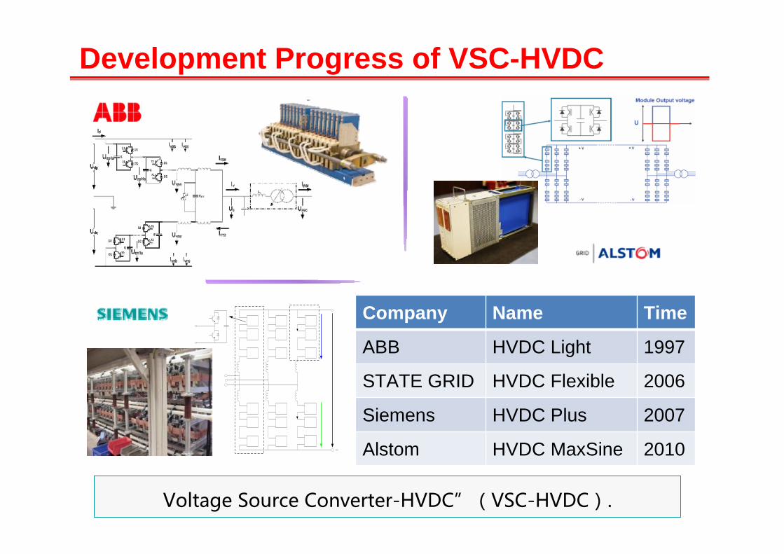
Development Progress of VSC-HVDC
Company Name Time
ABB HVDC Light 1997
STATE GRID HVDC Flexible 2006
Siemens HVDC Plus 2007
Alstom HVDC MaxSine 2010
Voltage Source Converter-HVDC”(VSC-HVDC).

2. DC Distribution Network
Closed loopRadial Parallel Connection Mixed Connection

It is difficult to break DC current because the fault current has no natural zero-crossing point.To avoid DC system collapse, DC circuit breaker should be able to interrupt fault as fast as possible. At least the action time should reach a few hundreds microseconds level or a few milliseconds.
Mechanical Solid State Hybrid
Breaking Speed Breaking Capacity Topology Control Loss
Mechanical Slow(Tens of milliseconds) Large Simple Easy Low
Solid StateFast(Hundreds
of microseconds)
Small Moderate Moderate High
Hybrid Medium(A few milliseconds) Medium Complicated Difficult Medium
Key Technologies of Fault IsolationCircuit Breaker of DC system

The current in DC power grid rises rapidly with high amplitude, so the time of
protection action should be in several milliseconds or even microseconds.
The configuration of protection depends on the power grid scale, converter
topology, the configuration of circuit breaker and many other factors, so
protection strategies are complex and diverse.
Key Technologies of Fault IsolationProtection of DC system
0.00 0.02 0.04 0.06 0.08 0.100.0
0.2
0.4
0.6
0.8
1.0
续流
电流
/kA
时间/s
电容放电电流
放电
Fault current in DC power system

4
Backgrounds1
2
3
DC Distribution Network
Protection and Fault Isolation
Conclusions
17
Outline

1
23 4
5
67
8
1. VSC valve2. valve reactor3. Transformer4. starting resistance
3. Protection and Fault Isolation Main Electric Connection of DC System
AC system protection
Transformer protection
Converter protection DC system
protection
5. Arrester6. grounding resistance7. DC cable8. lightning arrester

3. Protection and Fault Isolation Fault Types and Positions
External AC system ①②
common short-circuit and grounding fault
Internal AC
system
③④ AC bus fault
⑤⑥ bridge arm reactance grounding fault
Valve
⑦⑧ valve grounding fault
⑨ valve flashover fault
⑩ valve phase flashover fault
DC system
⑾⒀ Singlepolar grounding fault
⑿⒁ Bipolar short-circuit fault
Time(s)1t
2t
1Di 3Di 5Di1 3 5 AD , ,i ( )
ai bi ciAabci ( )
Ali( )
Vdcu( )
DC capacitor discharging
3t
Diodes naturallyCommutation conducting
Diodes conductsynchronously
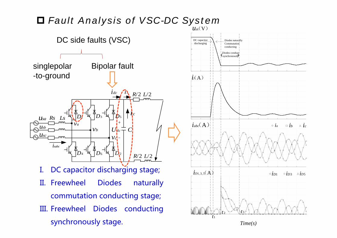
Fault Analysis of VSC-DC System
Rs Lsav
bvcvdcU
C
sabci
dci li /2R /2L
/2R /2L
sausbuscu
ci1D 3D 5D
4D 6D 2D
DC side faults (VSC)
singlepolar-to-ground
Bipolar fault
I. DC capacitor discharging stage;
II. Freewheel Diodes naturally
commutation conducting stage;
III. Freewheel Diodes conducting
synchronously stage.

Time(s)1t
2t
1Di 3Di 5Di1 3 5 AD , ,i ( )
ai bi ciAabci ( )
Ali( )
Vdcu( )
DC capacitor discharging
3t
Diodes naturallyCommutation conducting
Diodes conductsynchronously
Fault Analysis of VSC-DC System
DC side faults(VSC)
Diodes conductsynchronously
DC capacitordischarging
Diodes naturallycommutationconducting
Converter:IGBTblocked
AC side:current not rising
DC side:DC voltage dropping
AC side:Feeding small current to the diodes
DC side:DC voltage drop
AC side:Three-phase fault
Diodes:Overcurrent shocking
DC side:Inductance discharging
DC capacitordischarging
Diodes naturallycommutationconducting
singlepolar-to-ground Bipolar fault

Bipolar short-circuit fault(most serious)
Time S
li
La _ upi
abci ai bi ci
Unit(A)
Fault Analysis of MMC-DC System
sau
sbu
scu
Rs sL LR
1T
LR
Rs sL LRLR
Rs sL LRLR
2T
1D
2DC
1T
2T
1D
2DC
1T
2T
1D
2DC
1T
2T
1D
2DC
1T
2T
1D
2DC
1T
2T
1D
2DC
1T
2T
1D
2DC
1T
2T
1D
2DC
1T
2T
1D
2DC
1T
2T
1D
2DC
1T
2T
1D
2DC
1T
2T
1D
2DC
2lR / 2lL /
2lL /2lR /
I. SM not blocked;
II. Initial stage after blocking SM
III. Uncontrolled rectification stage
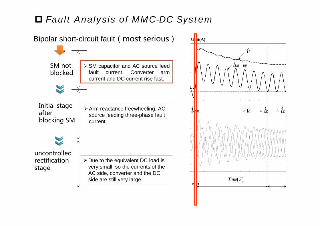
Bipolar short-circuit fault(most serious)
Time S
li
La _ upi
abci ai bi ci
Unit(A)
Fault Analysis of MMC-DC System
SM notblocked
Initial stage after blocking SM
uncontrolled rectificationstage
SM capacitor and AC source feed fault current. Converter arm current and DC current rise fast.
Arm reactance freewheeling, AC source feeding three-phase fault current.
Due to the equivalent DC load is very small, so the currents of the AC side, converter and the DC side are still very large

Open AC side circuit breaker
Block IGBT Circuit breakers of AC side trip
Isolate fault linewith DC switch
Reclose AC side circuit breakerRestore AC side power supplyReduce area of blackout
Converter blockClear up the DC faults by the improvement of the converter topology and the cooperation of the control strategy.
• Long switching time
• High investment• Large power loss
DC circuit breaker • Action time• Switching capacity
11SW 12SW
31SW
33SW
22SW
23SW
1Line
3Line 2Line
11SW 12SW
31SW
33SW
22SW
23SW
1Line
3Line 2Line
11SW 12SW
31SW
33SW
22SW
23SW
1Line
3Line 2Line
1T
2T
1D
2DC
3T
4T
3D
4D
1T
2T
1D
2DC
3T
4T
3D
4D
Fault Isolation Strategies
• Low reliability of power supply

Vdcu( )
Ali( )
ai bi ciAabci ( )
1Di 3Di 5Di1 3 5 AD , ,i ( )
Time(s)
AC side
Converter
SFCL
SFCL
Normal state
Superconducting state
Ic
Hc
Tc
Normal state
Normal state
Superconducting limiting
DC faultSFCL quenchResistance rises to increase damping effect
Isolate the fault by DC-CB
AC side :Three-phase fault is avoided Converter:Overcurrent of the diodes
is eliminated DC side:Overcurrent is limited DC-CB:Action time is extended
Switching capacity is reduced
Fault Isolation Technologies
Decreased significantly
No zero-crossing point

Converter limiting
T
D
lim iterRCC
1D 1D 2D2D
1T 1T2T 2T
T
D
lim iterRCC
1D 1D 2D2D
1T 1T2T 2T
T
D
lim iterRCC
1D 1D 2D2D
1T 1T2T 2T
Time S
li A
abc Ai ai bi ci
_La upi A
Fault currents of AC side, DC side and converter are limited
Investment and power loss are low The requirements for the action
time and switching capacity of the DC-CB are decreased
Fault Isolation Technologies Decreased significantly

Over-current Protection Simplicity. If i>imax, protections will operate All branch currents are increased when a
fault occurs. Action velocity, Selectivity, Sensitivity.
Reliability
Differential Protection intrinsic selectivity Problems in communication with
long lines: complexity and delay Action velocity
Distance Protection
Protection Technologies
The cable impedance is so small that the measurement errors will result in protection failure. So the traditional distance protection is not available

4
Backgrounds1
2
3
DC Distribution Network
Protection and Fault Isolation
Conclusions
32
Outline

4. Conclusions
DC distribution networks is suitable for integration of
DGs, improving efficiency of energy uThe current in DC
power grid rises rapidly with high amplitude, so the time of
protection action should be in several milliseconds or even
microseconds.
The configuration of protection depends on the power
grid scale, converter topology, the configuration of circuit
breaker and many other factors, so protection strategies
are complex and diverse.
tilization, etc.

DC Distribution Platform in Tianjin University
±200VDC
DCDC
ACDC
10 kVA
BUS1
5 kW
380/220V
PV BATTERYSTORAGEDEVICES
DC LOADDC LOAD
QF8 QF9LINE1 QF1-2QF1-1
LINE6 QF6-2QF6-1
ACDC5 kW
WIND POWER
±200VDCBUS2
5 kW
5 kW 5 kW 5 kW 5 kW
QF2-2QF2-1 LINE2
QF5-2QF5-1 LINE5
±200VDCBUS3
ACDC
ACDC
10 kVA220/380V
DCDC
DCDC
QF3-2QF3-1 LINE3
±200VDCBUS4
QF4-2QF4-1 LINE4
DCDC
DC LOAD
DCDC
±200VDCBUS6
±200VDCBUS5
DC LOAD
Low-Voltage Bipolar-Type ±200VDC Two Bi-directional DC/AC Converters Multi-terminal DC-links --- 6 DC Buses Meshed Network
Characteristics: