Johnson Matthey Metal Joining - Brazing and Soldering Pastes

2
3
Introduction
4 About Johnson Matthey
6 The Benefits of Using a Brazing or Soldering Paste
The JM Metal Joining Paste Product Range
8 Application Profile for Brazing and Soldering Pastes
9 Temperature Profile for Brazing and Soldering Pastes
10 Filler Metals, Fluxes and Binder Systems
11 Binder Systems for Soldering Pastes, Binder Systems for Aluminium Brazing
Pastes
12 Binder Systems With Flux for Silver and Copper Based Brazing Pastes
13 Binder Systems for Furnace Brazing Applications
How to Use Brazing and Soldering Pastes
14 Dispensing and Location of Paste Deposits
16 Heating Methods for Brazing and Soldering Pastes
18 Heating Brazing Pastes and Removal of Residues After Heating
19 Heating Soldering Pastes and Removal of Residues After Heating
20 Storage of Pastes and Shelf Life
22 Dispensing Equipment for Automation or Semi-Automation
of the Joining Process
23 Some Guidelines for Using Pastes
Further Information
24 The JM Metal Joining Paste Product Range - Alloy Reference Chart
27 The Environment and Health and Safety
Disclaimer, Copyright and Acknowledgements
4
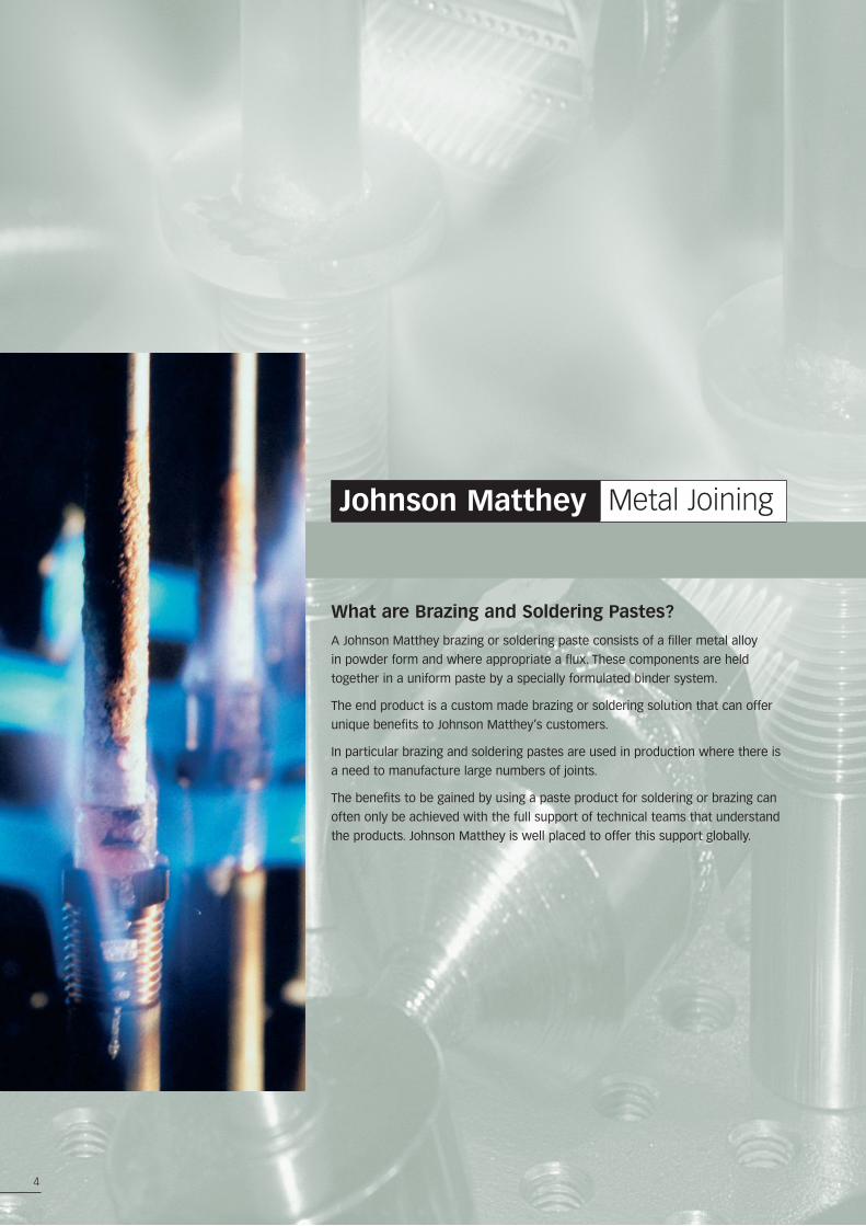
What are Brazing and Soldering Pastes?
A Johnson Matthey brazing or soldering paste consists of a filler metal alloy
in powder form and where appropriate a flux. These components are held
together in a uniform paste by a specially formulated binder system.
The end product is a custom made brazing or soldering solution that can offer
unique benefits to Johnson Matthey’s customers.
In particular brazing and soldering pastes are used in production where there is
a need to manufacture large numbers of joints.
The benefits to be gained by using a paste product for soldering or brazing can
often only be achieved with the full support of technical teams that understand
the products. Johnson Matthey is well placed to offer this support globally.
Johnson Matthey Metal Joining
5
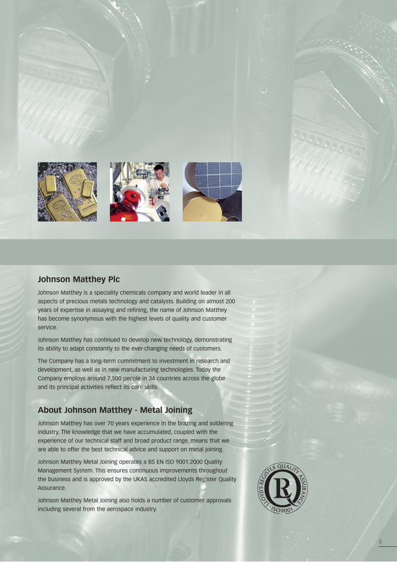
Johnson Matthey Plc
Johnson Matthey is a speciality chemicals company and world leader in all
aspects of precious metals technology and catalysts. Building on almost 200
years of expertise in assaying and refining, the name of Johnson Matthey
has become synonymous with the highest levels of quality and customer
service.
Johnson Matthey has continued to develop new technology, demonstrating
its ability to adapt constantly to the ever-changing needs of customers.
The Company has a long-term commitment to investment in research and
development, as well as in new manufacturing technologies. Today the
Company employs around 7,500 people in 34 countries across the globe
and its principal activities reflect its core skills.
About Johnson Matthey - Metal Joining
Johnson Matthey has over 70 years experience in the brazing and soldering
industry. The knowledge that we have accumulated, coupled with the
experience of our technical staff and broad product range, means that we
are able to offer the best technical advice and support on metal joining.
Johnson Matthey Metal Joining operates a BS EN ISO 9001:2000 Quality
Management System. This ensures continuous improvements throughout
the business and is approved by the UKAS accredited Lloyds Register Quality
Assurance.
Johnson Matthey Metal Joining also holds a number of customer approvals
including several from the aerospace industry.
The Benefits of Using a Johnson Matthey Brazing or Soldering Paste
6
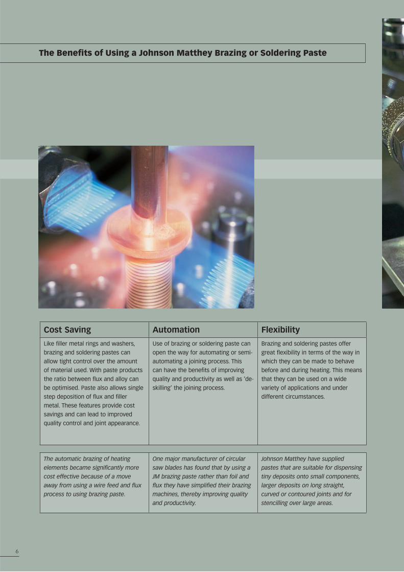
Cost Saving Automation Flexibility
Like filler metal rings and washers,
brazing and soldering pastes can
allow tight control over the amount
of material used. With paste products
the ratio between flux and alloy can
be optimised. Paste also allows single
step deposition of flux and filler
metal. These features provide cost
savings and can lead to improved
quality control and joint appearance.
Use of brazing or soldering paste can
open the way for automating or semi-
automating a joining process. This
can have the benefits of improving
quality and productivity as well as ‘de-
skilling’ the joining process.
Brazing and soldering pastes offer
great flexibility in terms of the way in
which they can be made to behave
before and during heating. This means
that they can be used on a wide
variety of applications and under
different circumstances.
The automatic brazing of heating
elements became significantly more
cost effective because of a move
away from using a wire feed and flux
process to using brazing paste.
One major manufacturer of circular
saw blades has found that by using a
JM brazing paste rather than foil and
flux they have simplified their brazing
machines, thereby improving quality
and productivity.
Johnson Matthey have supplied
pastes that are suitable for dispensing
tiny deposits onto small components,
larger deposits on long straight,
curved or contoured joints and for
stencilling over large areas.
7
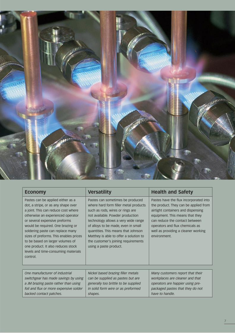
Economy Versatility Health and Safety
Pastes can be applied either as a
dot, a stripe, or as any shape over
a joint. This can reduce cost where
otherwise an experienced operator
or several expensive preforms
would be required. One brazing or
soldering paste can replace many
sizes of preforms. This enables prices
to be based on larger volumes of
one product. It also reduces stock
levels and time-consuming materials
control.
Pastes can sometimes be produced
where hard form filler metal products
such as rods, wires or rings are
not available. Powder production
technology allows a very wide range
of alloys to be made, even in small
quantities. This means that Johnson
Matthey is able to offer a solution to
the customer’s joining requirements
using a paste product.
Pastes have the flux incorporated into
the product. They can be applied from
airtight containers and dispensing
equipment. This means that they
can reduce the contact between
operators and flux chemicals as
well as providing a cleaner working
environment.
One manufacturer of industrial
switchgear has made savings by using
a JM brazing paste rather than using
foil and flux or more expensive solder
backed contact patches.
Nickel based brazing filler metals
can be supplied as pastes but are
generally too brittle to be supplied
in solid form wire or as preformed
shapes.
Many customers report that their
workplaces are cleaner and that
operators are happier using pre-
packaged pastes that they do not
have to handle.
Application Profile for Brazing and Soldering Pastes
8
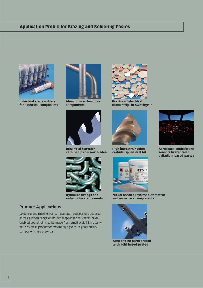
Product Applications
Soldering and Brazing Pastes have been successfully adapted
across a broad range of industrial applications. Pastes have
enabled sound joints to be made from small-scale high quality
work to mass production where high yields of good quality
components are essential.
Industrial grade solders for electrical components
Aluminium automotive components
Brazing of electrical contact tips in switchgear
Brazing of tungsten carbide tips on saw blades
High impact tungsten carbide tipped drill bit
Aerospace controls and sensors brazed with palladium based pastes
Hydraulic fittings and automotive components
Nickel based alloys for automotive and aerospace components
Aero engine parts brazed with gold based pastes
Temperature Profile for Brazing and Soldering Pastes
9
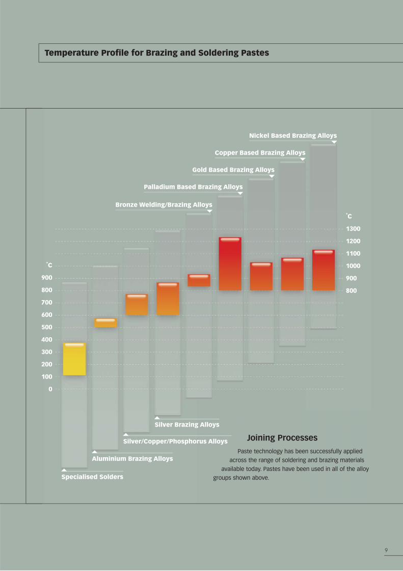
Silver Brazing Alloys
˚C
900
800
700
600
500
400
300
200
100
0
˚C
1300
1200
1100
1000
900
800
Bronze Welding/Brazing Alloys
Palladium Based Brazing Alloys
Gold Based Brazing Alloys
Copper Based Brazing Alloys
Nickel Based Brazing Alloys
Silver/Copper/Phosphorus Alloys
Aluminium Brazing Alloys
Specialised Solders
Joining Processes
Paste technology has been successfully applied
across the range of soldering and brazing materials
available today. Pastes have been used in all of the alloy
groups shown above.
10
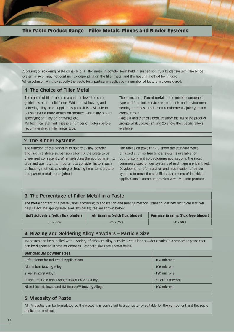
The Paste Product Range – Filler Metals, Fluxes and Binder Systems
A brazing or soldering paste consists of a filler metal in powder form held in suspension by a binder system. The binder
system may or may not contain flux depending on the filler metal and the heating method being used.
When Johnson Matthey specify the paste for a particular application a number of factors are considered.
1. The Choice of Filler MetalThe choice of filler metal in a paste follows the same
guidelines as for solid forms. Whilst most brazing and
soldering alloys can supplied as paste it is advisable to
consult JM for more details on product availability before
specifying an alloy on drawings etc.
JM Technical staff will assess a number of factors before
recommending a filler metal type.
These include: - Parent metals to be joined, component
type and function, service requirements and environment,
heating methods, production requirements, joint gap and
configuration.
Pages 8 and 9 of this booklet show the JM paste product
groups whilst pages 24 and 26 show the specific alloys
available.
2. The Binder SystemsThe function of the binder is to hold the alloy powder
and flux in a stable suspension allowing the paste to be
dispensed consistently. When selecting the appropriate flux
type and quantity it is important to consider factors such
as heating method, soldering or brazing time, temperature
and parent metals to be joined.
The tables on pages 11-13 show the standard types
of fluxed and flux free binder systems available for
both brazing and soft soldering applications. The most
commonly used binder systems of each type are identified.
Development, reformulation and modification of binder
systems to meet the specific requirements of individual
applications is common practice with JM paste products.
3. The Percentage of Filler Metal in a PasteThe metal content of a paste varies according to application and heating method. Johnson Matthey technical staff will
help select the appropriate level. Typical figures are shown below.
Soft Soldering (with flux binder) Air Brazing (with flux binder) Furnace Brazing (flux-free binder)
75 - 88% 65 - 75% 80 - 90%
4. Brazing and Soldering Alloy Powders – Particle SizeJM pastes can be supplied with a variety of different alloy particle sizes. Finer powder results in a smoother paste that
can be dispensed in smaller deposits. Standard sizes are shown below.
Standard JM powder sizes
Soft Solders for Industrial Applications -106 microns
Aluminium Brazing Alloy -106 microns
Silver Brazing Alloys -180 microns
Palladium, Gold and Copper Based Brazing Alloys -75 or 53 microns
Nickel Based, Brass and JM Bronze™ Brazing Alloys -106 microns
5. Viscosity of PasteAll JM pastes can be formulated so the viscosity is controlled to a consistency suitable for the component and the paste
application method.
11
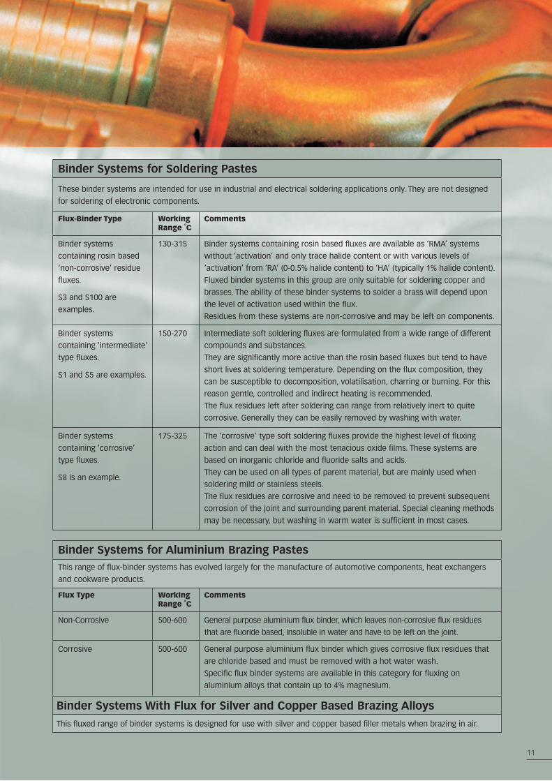
Binder Systems for Soldering Pastes
These binder systems are intended for use in industrial and electrical soldering applications only. They are not designed
for soldering of electronic components.
Flux-Binder Type Working Range ˚C
Comments
Binder systems
containing rosin based
‘non-corrosive’ residue
fluxes.
S3 and S100 are
examples.
130-315 Binder systems containing rosin based fluxes are available as ‘RMA’ systems
without ‘activation’ and only trace halide content or with various levels of
‘activation’ from ‘RA’ (0-0.5% halide content) to ‘HA’ (typically 1% halide content).
Fluxed binder systems in this group are only suitable for soldering copper and
brasses. The ability of these binder systems to solder a brass will depend upon
the level of activation used within the flux.
Residues from these systems are non-corrosive and may be left on components.
Binder systems
containing ‘intermediate’
type fluxes.
S1 and S5 are examples.
150-270 Intermediate soft soldering fluxes are formulated from a wide range of different
compounds and substances.
They are significantly more active than the rosin based fluxes but tend to have
short lives at soldering temperature. Depending on the flux composition, they
can be susceptible to decomposition, volatilisation, charring or burning. For this
reason gentle, controlled and indirect heating is recommended.
The flux residues left after soldering can range from relatively inert to quite
corrosive. Generally they can be easily removed by washing with water.
Binder systems
containing ‘corrosive’
type fluxes.
S8 is an example.
175-325 The ‘corrosive’ type soft soldering fluxes provide the highest level of fluxing
action and can deal with the most tenacious oxide films. These systems are
based on inorganic chloride and fluoride salts and acids.
They can be used on all types of parent material, but are mainly used when
soldering mild or stainless steels.
The flux residues are corrosive and need to be removed to prevent subsequent
corrosion of the joint and surrounding parent material. Special cleaning methods
may be necessary, but washing in warm water is sufficient in most cases.
Binder Systems for Aluminium Brazing PastesThis range of flux-binder systems has evolved largely for the manufacture of automotive components, heat exchangers
and cookware products.
Flux Type Working Range ˚C
Comments
Non-Corrosive 500-600 General purpose aluminium flux binder, which leaves non-corrosive flux residues
that are fluoride based, insoluble in water and have to be left on the joint.
Corrosive 500-600 General purpose aluminium flux binder which gives corrosive flux residues that
are chloride based and must be removed with a hot water wash.
Specific flux binder systems are available in this category for fluxing on
aluminium alloys that contain up to 4% magnesium.
Binder Systems With Flux for Silver and Copper Based Brazing Alloys
This fluxed range of binder systems is designed for use with silver and copper based filler metals when brazing in air.
12
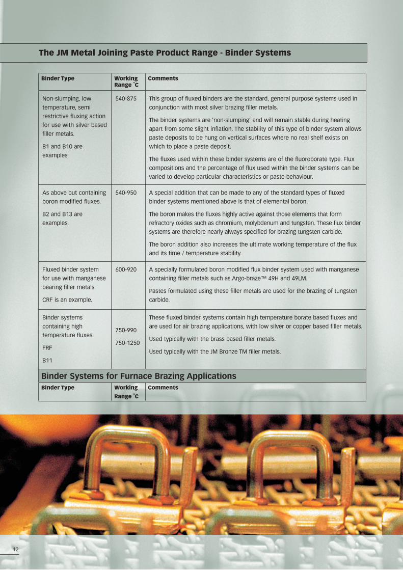
The JM Metal Joining Paste Product Range - Binder Systems
Binder Type Working Range ˚C
Comments
Non-slumping, low
temperature, semi
restrictive fluxing action
for use with silver based
filler metals.
B1 and B10 are
examples.
540-875 This group of fluxed binders are the standard, general purpose systems used in
conjunction with most silver brazing filler metals.
The binder systems are ‘non-slumping’ and will remain stable during heating
apart from some slight inflation. The stability of this type of binder system allows
paste deposits to be hung on vertical surfaces where no real shelf exists on
which to place a paste deposit.
The fluxes used within these binder systems are of the fluoroborate type. Flux
compositions and the percentage of flux used within the binder systems can be
varied to develop particular characteristics or paste behaviour.
As above but containing
boron modified fluxes.
B2 and B13 are
examples.
540-950 A special addition that can be made to any of the standard types of fluxed
binder systems mentioned above is that of elemental boron.
The boron makes the fluxes highly active against those elements that form
refractory oxides such as chromium, molybdenum and tungsten. These flux binder
systems are therefore nearly always specified for brazing tungsten carbide.
The boron addition also increases the ultimate working temperature of the flux
and its time / temperature stability.
Fluxed binder system
for use with manganese
bearing filler metals.
CRF is an example.
600-920 A specially formulated boron modified flux binder system used with manganese
containing filler metals such as Argo-braze™ 49H and 49LM.
Pastes formulated using these filler metals are used for the brazing of tungsten
carbide.
Binder systems
containing high
temperature fluxes.
FRF
B11
750-990
750-1250
These fluxed binder systems contain high temperature borate based fluxes and
are used for air brazing applications, with low silver or copper based filler metals.
Used typically with the brass based filler metals.
Used typically with the JM Bronze TM filler metals.
Binder Systems for Furnace Brazing ApplicationsBinder Type Working
Range ˚C
Comments
13
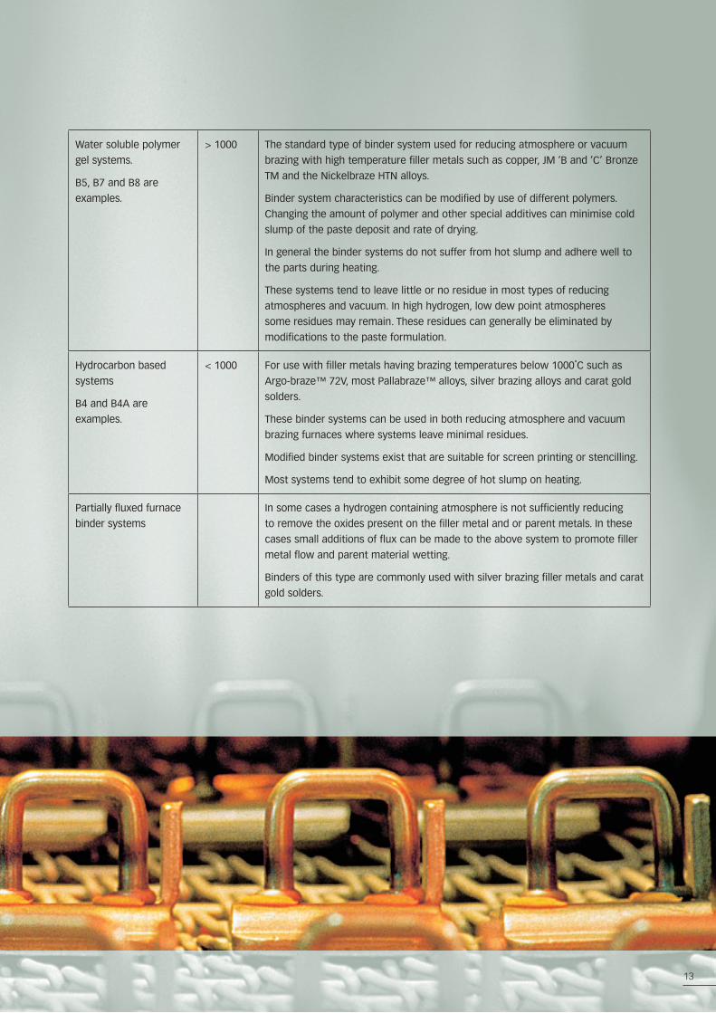
Water soluble polymer
gel systems.
B5, B7 and B8 are
examples.
> 1000 The standard type of binder system used for reducing atmosphere or vacuum
brazing with high temperature filler metals such as copper, JM ‘B and ‘C’ Bronze
TM and the Nickelbraze HTN alloys.
Binder system characteristics can be modified by use of different polymers.
Changing the amount of polymer and other special additives can minimise cold
slump of the paste deposit and rate of drying.
In general the binder systems do not suffer from hot slump and adhere well to
the parts during heating.
These systems tend to leave little or no residue in most types of reducing
atmospheres and vacuum. In high hydrogen, low dew point atmospheres
some residues may remain. These residues can generally be eliminated by
modifications to the paste formulation.
Hydrocarbon based
systems
B4 and B4A are
examples.
< 1000 For use with filler metals having brazing temperatures below 1000˚C such as
Argo-braze™ 72V, most Pallabraze™ alloys, silver brazing alloys and carat gold
solders.
These binder systems can be used in both reducing atmosphere and vacuum
brazing furnaces where systems leave minimal residues.
Modified binder systems exist that are suitable for screen printing or stencilling.
Most systems tend to exhibit some degree of hot slump on heating.
Partially fluxed furnace
binder systems
In some cases a hydrogen containing atmosphere is not sufficiently reducing
to remove the oxides present on the filler metal and or parent metals. In these
cases small additions of flux can be made to the above system to promote filler
metal flow and parent material wetting.
Binders of this type are commonly used with silver brazing filler metals and carat
gold solders.
14
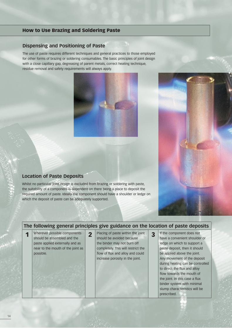
Dispensing and Positioning of Paste
The use of paste requires different techniques and general practices to those employed
for other forms of brazing or soldering consumables. The basic principles of joint design
with a close capillary gap, degreasing of parent metals, correct heating technique,
residue removal and safety requirements will always apply.
Location of Paste Deposits
Whilst no particular joint design is excluded from brazing or soldering with paste,
the suitability of a component is dependent on there being a place to deposit the
required amount of paste. Ideally the component should have a shoulder or ledge on
which the deposit of paste can be adequately supported.
How to Use Brazing and Soldering Paste
The following general principles give guidance on the location of paste deposits
1 Wherever possible components
should be assembled and the
paste applied externally and as
near to the mouth of the joint as
possible.
2 Placing of paste within the joint
should be avoided because
the binder may not burn off
completely. This will restrict the
flow of flux and alloy and could
increase porosity in the joint.
3 If the component does not
have a convenient shoulder or
ledge on which to support a
paste deposit, then it should
be applied above the joint.
Any movement of the deposit
during heating can be controlled
to direct the flux and alloy
flow towards the mouth of
the joint. In this case a flux
binder system with minimal
slump characteristics will be
prescribed.
15
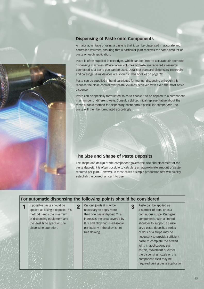
Dispensing of Paste onto Components
A major advantage of using a paste is that it can be dispensed in accurate and
controlled volumes, ensuring that a particular joint receives the same amount of
paste on each application.
Paste is often supplied in cartridges, which can be fitted to accurate air operated
dispensing machines. Where larger volumes of paste are required a reservoir
connected to a paste gun can be used. Details of standard dispensers, reservoirs
and cartridge filling devices are shown in this booklet on page 22.
Paste can be supplied in hand cartridges for manual dispensing although this
reduces the close control over paste volumes achieved with even the most basic
dispenser.
Paste can be specially formulated so as to enable it to be applied to a component
in a number of different ways. Consult a JM technical representative about the
most suitable method for dispensing paste onto a particular component. The
paste will then be formulated accordingly.
For automatic dispensing the following points should be considered
1 If possible paste should be
applied as a single deposit. This
method needs the minimum
of dispensing equipment and
the least time spent on the
dispensing operation.
2 On long joints it may be
necessary to apply more
than one paste deposit. This
increases the area covered by
flux and alloy and is advisable
particularly if the alloy is not
free flowing.
3 Paste can be applied as
a number of dots, or as a
continuous stripe. On bigger
components, with a limited
shoulder to support a single
large paste deposit, a series
of dots or a stripe may be
necessary to provide sufficient
paste to complete the brazed
joint. In applications such
as this, movement of either
the dispensing nozzle or the
component itself may be
required during paste application.
The Size and Shape of Paste Deposits
The shape and design of the component govern the size and placement of the
paste deposit. It is often possible to calculate an approximate amount of paste
required per joint. However, in most cases a simple production test will quickly
establish the correct amount to use.
16
How to use Brazing and Soldering Paste
Heating Methods
JM Paste products can be used successfully with most of the standard heating methods.
The most common are listed here.
Fixed Burners Furnace Heating Induction Heating
With fixed burners the requirement
for operator skill and experience
can be overcome and a correct,
reproducible heat pattern can be
found for most components.
Ranges of burners are available
using a variety of fuels from gas / air
through to oxygen / gas systems. The
final choice of fuel is usually based
on availability together with size of
components and required production
rates.
Fixed burners can be used as simple
arrangements of single or double
burners, on basic shuttle machines
or on rotary indexing machines.
The burners and heating cycles
can ultimately be controlled by pc
systems.
Pastes can be formulated to suit the
requirements of most furnace brazing
or soldering applications.
Furnace heating is widely used
for brazing. It uses a reducing
atmosphere or vacuum to remove or
break up surface oxides and prevent
their formation during the brazing
process. Furnace brazing is usually
a flux free operation. If the oxides
present on the parent metals are
particularly difficult to reduce then a
small amount of flux may be added
to the paste to improve cleaning and
wetting of the molten alloy.
During furnace brazing the whole
component will reach brazing
temperature. Pre-placement of
the filler metal prior to heating is
required. For this reason the position
of the paste deposit and its properties
are particularly important.
Brazing and soldering pastes are
widely used with this heating
technique. It provides quick and easily
controlled heating. Occasionally rapid
heating of the component may cause
the paste to move or spit due to
vaporisation of the binder. This can be
overcome by moderating the power
input or modifying the design of the
induction coil.
Once conditions are set, induction
offers an efficient heating method,
which gives a heat pattern well suited
to paste products.
17
Resistance Heating Hand Torch
Brazing and soldering pastes work
well with resistance heating methods.
Resistance heating with a separate
alloy and flux can cause problems
because the flux acts as an insulator.
With paste this is largely overcome
because the finely divided powder
offers a conductive path through the
flux.
Pastes with a high metal content are
specified in conjunction with a flux
that becomes active very quickly
since the fast heating rate reduces
the time for the flux to be effective on
the parent metals.
Paste is suitable for heating by hand
torch. Operators experienced in
brazing or soldering with separate
rod and flux will need to modify their
brazing technique when using paste.
When hand torch brazing the operator
will normally heat the joint area
directly with the flame to reach
brazing temperature as quickly as
possible. Pastes should be heated
indirectly rather than with the full
torch flame. This is because the
deposit if heated directly, will reach
brazing temperatures long before the
parent metals. In this case the flux
in the paste will not have sufficient
time to clean the parent metals and
the molten alloy will not wet out
onto the joint area. In the worst case
the molten alloy may ball up and roll
away from the joint.
Heating the paste indirectly will allow
the paste deposit to reach the correct
temperature at the same rate as the
rest of the component. In this case
the flux will function correctly. The
overall heat pattern should ensure
that a temperature gradient exists in
the joint area so that flux and molten
alloy will flow into the joint.
18
How to use Brazing and Soldering Paste
18
Heating Brazing Paste
The behaviour and flow characteristics of a brazing paste when heated will depend upon its formulation, whether it
contains flux and the heating method being used. A typical fluxed paste for brazing in air with a silver brazing filler metal
based around the ‘B1’ binder system will go through the following stages.
1 On initial heating the paste deposit will increase in size. During this early stage of heating the paste deposit
should be heated slowly and indirectly to cause it to ‘set’. Heating it too rapidly or directly at this stage can
cause it to ‘explode’ or spit. Slow controlled heating is especially important if the paste has been hung on a
vertical surface.
2 With further heating, the paste will either start to smoke significantly, or if a flame is present will ignite. Where
ignition of the paste does not occur, for example when using RF induction or resistance heating, local exhaust
ventilation should be used to remove the fume from the working environment.
3 As the heating continues the paste’s appearance will change from a shiny, glossy deposit, to a dull, dry one. The
binder has now been lost from the paste which has become ‘set’. Once ‘set’ it is stable and can be subjected to
a more rapid rate of heating.
4 Next the flux starts to melt, ‘wetting’ the parent metals and reducing surface oxides on them. Initially this takes
place locally around the base of the paste deposit. As the temperature continues to increase the flux becomes
more fluid, spreading out and flowing into the capillary gap present within the joint.
5 Finally, as more heat is applied the filler metal will begin to melt and then flow completely. The rate of heating
at this stage needs to be sufficient to prevent liquation of the filler metal. This is where the filler metal only
partially melts leaving behind a skull of solid material and resulting in a joint that is only partially filled.
Brazing pastes can be supplied that exhibit different characteristics to these during the heating cycle. Both the binder and
the flux in a paste can be changed or modified to match the needs of a particular brazing job. For example binder systems
can be supplied that collapse and spread onto a component where paste is needed over a large area.
Removal of Brazing Paste Residues after Heating
The flux residues of brazing pastes are corrosive and therefore their removal after brazing is essential. They are similar to
those generated in other brazing operations and may be removed by the same methods - soaking in hot water (> 40˚C for 30
minutes), soaking in 10% sulphuric acid or by mechanical removal (e.g. grit blasting). The method should depend on the type of
flux present. Brazing pastes often leave a ‘footprint’ or mark on the component that is difficult to remove after brazing.
For advice on the best method of removing the flux residues please consult Johnson Matthey.
19
Heating Soldering Paste
Solder Pastes are formulated around totally different binder systems and flux types to those used for brazing and they
therefore react completely differently to brazing pastes when heated.
1 All solder paste when heated initially will exhibit some slump depending upon its formulation. With further
heating the deposit may bubble and heave (foam) and begin to smoke. Local exhaust ventilation to remove the
smoke from the working environment should be used. If heated too rapidly the paste deposit can boil and spit.
Gentle, indirect heating of solder paste is recommended throughout the soldering process. For this reason hot
air heating is a very good method for use with solder pastes.
2 With most binder systems the flux spreads and flows as the soldering paste slumps during heating. It becomes
more fluid as the temperature is increased and should remain colourless throughout the soldering operation. If
the flux starts to go brown it is an indication that either it is beginning to become exhausted or that the paste
has been overheated.
3 As the solder alloy within the paste begins to melt, the flux is displaced from the joint and floats on top of the
molten solder. Fluxes and solders will always flow to the hottest point of a joint and further flow of the solder,
into, along or around the joint can be encouraged by creating a thermal gradient across it. The temperature
should not be increased too much as this could induce flux exhaustion and the generation of fume.
4 If the solder fails to wet and flow as required or forms a molten ‘ball’ then this is an indication that the flux
has not been able to remove the oxides present on the surface of the parent materials. This could be due to
exposing the paste deposit to too high a temperature or exhausting the flux before the filler metal becomes
molten. Alternatively an inappropriate fluxed binder system was selected for the application.
Removal of Soldering Paste Residues after Heating
Flux residues from soldering paste are classified as non-corrosive, intermediate or corrosive. Non-corrosive residues may
be left on the completed joint. Intermediate or corrosive flux residues should be fully removed. Warm water, mildly alkaline
solution, or in the case of rosin based flux residues an organic solvent, should be used.
For advice on the best method of removing the flux residues please consult Johnson Matthey.
19
20
How to Use Brazing and Soldering Paste
Storing and Shelf Life
Brazing and soft soldering pastes have limited shelf life and strict stock rotation should be exercised during their storage.
The binder system and the filler metal powder can separate and the paste may dry out during storage. Separation or drying
out of a paste is more likely if the product is not stored correctly.
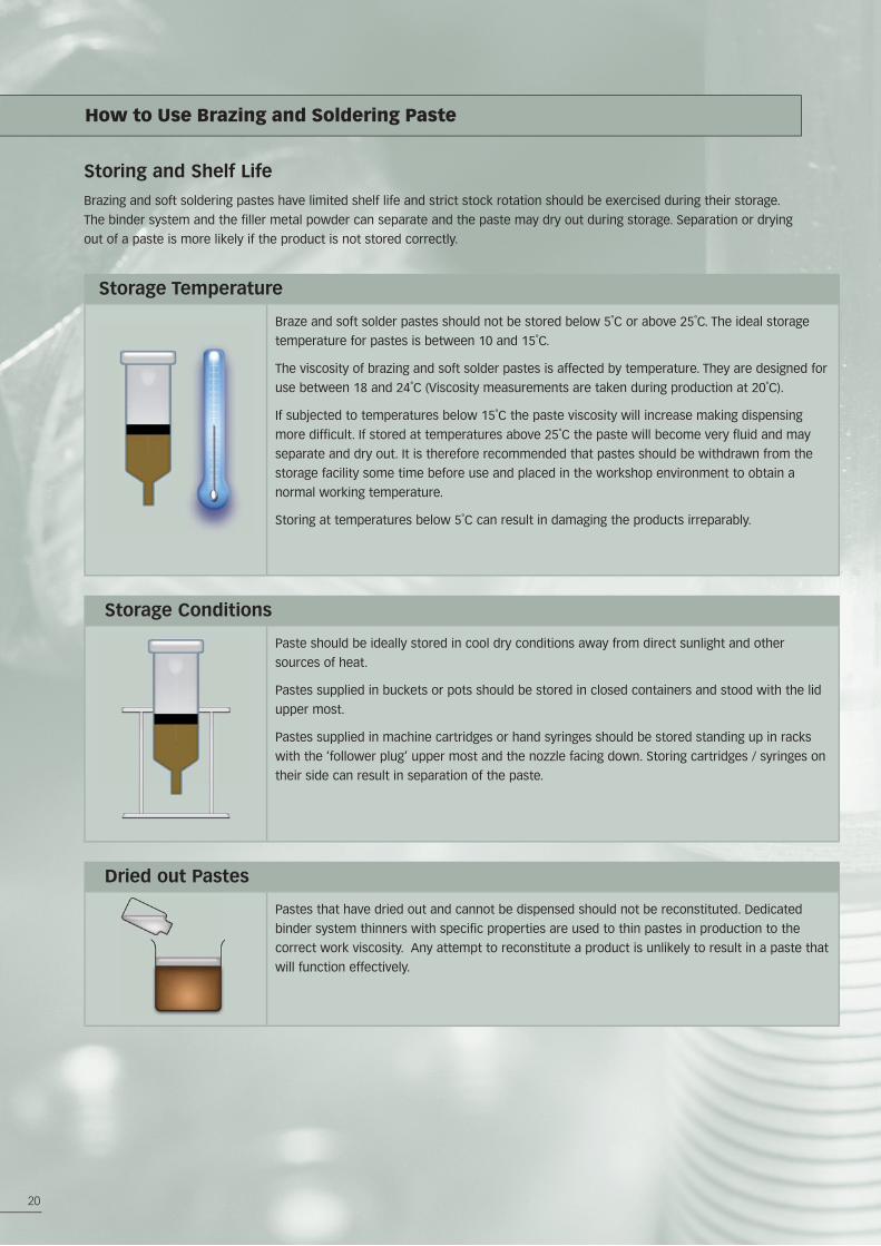
Storage Temperature
Braze and soft solder pastes should not be stored below 5˚C or above 25˚C. The ideal storage
temperature for pastes is between 10 and 15˚C.
The viscosity of brazing and soft solder pastes is affected by temperature. They are designed for
use between 18 and 24˚C (Viscosity measurements are taken during production at 20˚C).
If subjected to temperatures below 15˚C the paste viscosity will increase making dispensing
more difficult. If stored at temperatures above 25˚C the paste will become very fluid and may
separate and dry out. It is therefore recommended that pastes should be withdrawn from the
storage facility some time before use and placed in the workshop environment to obtain a
normal working temperature.
Storing at temperatures below 5˚C can result in damaging the products irreparably.
Storage Conditions
Paste should be ideally stored in cool dry conditions away from direct sunlight and other
sources of heat.
Pastes supplied in buckets or pots should be stored in closed containers and stood with the lid
upper most.
Pastes supplied in machine cartridges or hand syringes should be stored standing up in racks
with the ‘follower plug’ upper most and the nozzle facing down. Storing cartridges / syringes on
their side can result in separation of the paste.
Dried out Pastes
Pastes that have dried out and cannot be dispensed should not be reconstituted. Dedicated
binder system thinners with specific properties are used to thin pastes in production to the
correct work viscosity. Any attempt to reconstitute a product is unlikely to result in a paste that
will function effectively.
21
Storage Conditions
The shelf life of braze and soft solder pastes will be affected by the type of binder system used
to formulate the paste, the storage temperature, exposure to the air and the container size.
Pastes should only be considered unusable if they have dried out such that they cannot be
dispensed easily and correctly or show signs of binder separation.
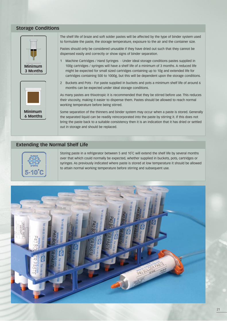
1 Machine Cartridges / Hand Syringes - Under ideal storage conditions pastes supplied in
100g cartridges / syringes will have a shelf life of a minimum of 3 months. A reduced life
might be expected for small sized cartridges containing up to 10g and extended life for
cartridges containing 500 to 1000g, but this will be dependent upon the storage conditions.
2 Buckets and Pots - For paste supplied in buckets and pots a minimum shelf life of around 6
months can be expected under ideal storage conditions.
As many pastes are thixotropic it is recommended that they be stirred before use. This reduces
their viscosity, making it easier to dispense them. Pastes should be allowed to reach normal
working temperature before being stirred.
Some separation of the thinners and binder system may occur when a paste is stored. Generally
the separated liquid can be readily reincorporated into the paste by stirring it. If this does not
bring the paste back to a suitable consistency then it is an indication that it has dried or settled
out in storage and should be replaced.
Extending the Normal Shelf Life
Storing paste in a refrigerator between 5 and 10˚C will extend the shelf life by several months
over that which could normally be expected, whether supplied in buckets, pots, cartridges or
syringes. As previously indicated where paste is stored at low temperature it should be allowed
to attain normal working temperature before stirring and subsequent use.
22
How to Use Brazing and Soldering Paste
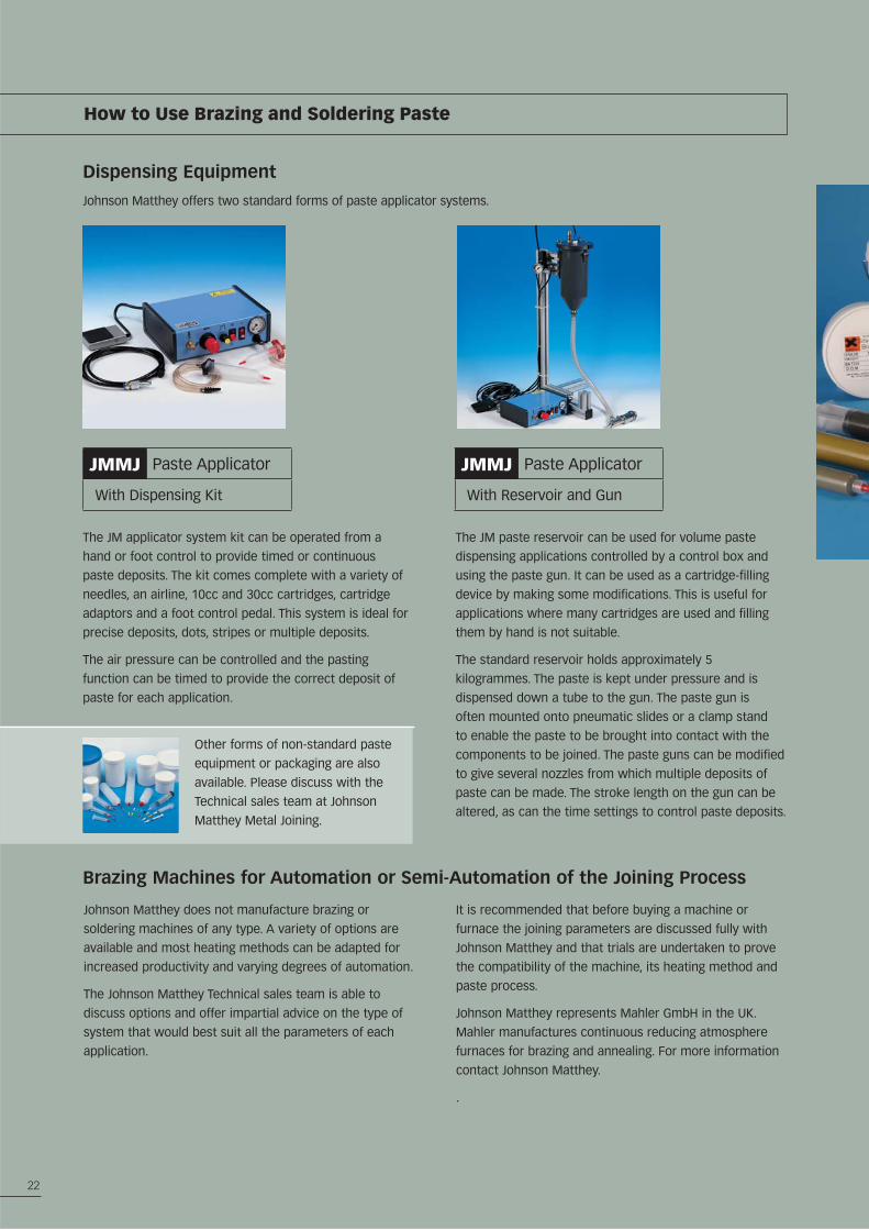
The JM applicator system kit can be operated from a
hand or foot control to provide timed or continuous
paste deposits. The kit comes complete with a variety of
needles, an airline, 10cc and 30cc cartridges, cartridge
adaptors and a foot control pedal. This system is ideal for
precise deposits, dots, stripes or multiple deposits.
The air pressure can be controlled and the pasting
function can be timed to provide the correct deposit of
paste for each application.
The JM paste reservoir can be used for volume paste
dispensing applications controlled by a control box and
using the paste gun. It can be used as a cartridge-filling
device by making some modifications. This is useful for
applications where many cartridges are used and filling
them by hand is not suitable.
The standard reservoir holds approximately 5
kilogrammes. The paste is kept under pressure and is
dispensed down a tube to the gun. The paste gun is
often mounted onto pneumatic slides or a clamp stand
to enable the paste to be brought into contact with the
components to be joined. The paste guns can be modified
to give several nozzles from which multiple deposits of
paste can be made. The stroke length on the gun can be
altered, as can the time settings to control paste deposits.
Other forms of non-standard paste
equipment or packaging are also
available. Please discuss with the
Technical sales team at Johnson
Matthey Metal Joining.
Johnson Matthey does not manufacture brazing or
soldering machines of any type. A variety of options are
available and most heating methods can be adapted for
increased productivity and varying degrees of automation.
The Johnson Matthey Technical sales team is able to
discuss options and offer impartial advice on the type of
system that would best suit all the parameters of each
application.
It is recommended that before buying a machine or
furnace the joining parameters are discussed fully with
Johnson Matthey and that trials are undertaken to prove
the compatibility of the machine, its heating method and
paste process.
Johnson Matthey represents Mahler GmbH in the UK.
Mahler manufactures continuous reducing atmosphere
furnaces for brazing and annealing. For more information
contact Johnson Matthey.
.
Dispensing Equipment
Johnson Matthey offers two standard forms of paste applicator systems.
Brazing Machines for Automation or Semi-Automation of the Joining Process
JMMJ Paste Applicator
With Dispensing Kit
JMMJ Paste Applicator
With Reservoir and Gun
23
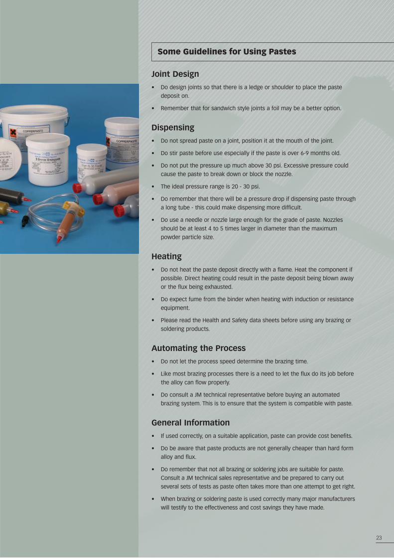
Some Guidelines for Using Pastes
Joint Design
• Do design joints so that there is a ledge or shoulder to place the paste
deposit on.
• Remember that for sandwich style joints a foil may be a better option.
Dispensing
• Do not spread paste on a joint, position it at the mouth of the joint.
• Do stir paste before use especially if the paste is over 6-9 months old.
• Do not put the pressure up much above 30 psi. Excessive pressure could
cause the paste to break down or block the nozzle.
• The ideal pressure range is 20 - 30 psi.
• Do remember that there will be a pressure drop if dispensing paste through
a long tube - this could make dispensing more difficult.
• Do use a needle or nozzle large enough for the grade of paste. Nozzles
should be at least 4 to 5 times larger in diameter than the maximum
powder particle size.
Heating
• Do not heat the paste deposit directly with a flame. Heat the component if
possible. Direct heating could result in the paste deposit being blown away
or the flux being exhausted.
• Do expect fume from the binder when heating with induction or resistance
equipment.
• Please read the Health and Safety data sheets before using any brazing or
soldering products.
Automating the Process
• Do not let the process speed determine the brazing time.
• Like most brazing processes there is a need to let the flux do its job before
the alloy can flow properly.
• Do consult a JM technical representative before buying an automated
brazing system. This is to ensure that the system is compatible with paste.
General Information
• If used correctly, on a suitable application, paste can provide cost benefits.
• Do be aware that paste products are not generally cheaper than hard form
alloy and flux.
• Do remember that not all brazing or soldering jobs are suitable for paste.
Consult a JM technical sales representative and be prepared to carry out
several sets of tests as paste often takes more than one attempt to get right.
• When brazing or soldering paste is used correctly many major manufacturers
will testify to the effectiveness and cost savings they have made.
24
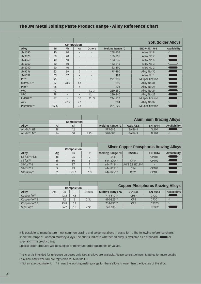
Soft Solder AlloysComposition
Alloy Sn Pb Ag Others Melting Range °C EN29453:1993 AvailabilityJM1090 10 90 - - 268-302 Alloy No 8JM3070 30 70 - - 185-255 Alloy No 7JM4060 40 60 - - 183-235 Alloy No 5JM5050 50 50 - - 183-215 Alloy No 3JM6040 60 40 - - 183-190 Alloy No 2JM6236 62 36 2 - 178-190 Alloy No 30JM6337 63 37 - - 183 Alloy No 1P5TM 95 - 5 - 221-235 JM SpecificationCOMSOLTM 5 93.5 1.5 - 296 Alloy No 34P40TM 96 - 4 - 221 Alloy No 2897C 97 - - Cu 3 230-250 Alloy No 2499C 99 - - Cu 1 230-240 Alloy No 23LM10ATM 87 - 10 Cu 3 214-217 JM SpecificationA25 - 97.5 2.5 - 304 Alloy No 32PlumbsolTM 97.5 - 2.5 - 221-225 JM Specification
Aluminium Brazing AlloysComposition
Alloy Al Si Melting Range °C AWS A5.8 EN 1044 AvailabilityAlu-floTM HT 88 12 575-585 BAISi- 4 AL104Alu-floTM MT 86 10 4 Cu 520-585 BAISi- 3 AL201
Silver Copper Phosphorus Brazing AlloysComposition
Alloy Ag Cu P Melting Range °C BS1845 EN 1044 AvailabilitySil-fosTM Plus 18 75 7 644 - CP101Sil-fosTM 15 80 5 644-800** CP1* CP102Sil-fosTM 6 6 87 7 644-718** AWS 5.8 BCuP-4 -Sil-fosTM 5 5 89 6 644-815** CP4 CP104SilbralloyTM 2 91.7 6.3 644-825** CP2* CP105
Copper Phosphorus Brazing AlloysComposition
Alloy Ag Cu P Others Melting Range °C BS1845 EN 1044 AvailabilityCopper-floTM 92.2 7.8 714-810** CP3* CP201Copper-floTM 2 92 6 2 Sb 690-825** CP5 CP301Copper-floTM 3 93.8 6.2 714-890** CP6 CP203Stan-fosTM 86.2 6.8 7 Sn 640-680 CP302
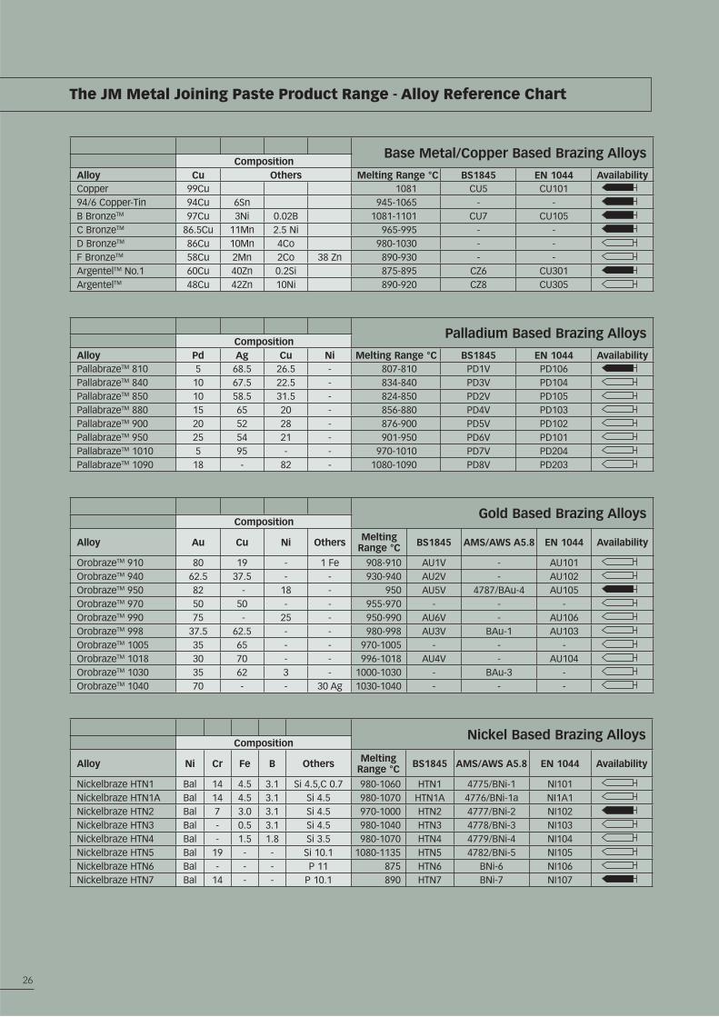
The JM Metal Joining Paste Product Range - Alloy Reference Chart
It is possible to manufacture most common brazing and soldering alloys in paste form. The following reference charts
show the range of Johnson Matthey alloys. The charts indicate whether an alloy is available as a standard or
special product line.
Special order products will be subject to minimum order quantities or values.
This chart is intended for reference purposes only. Not all alloys are available. Please consult Johnson Matthey for more details.
Easy-flo® and Silver-flo® are registered to JM in the EU.
* Not an exact equivalent. ** In use, the working melting range for these alloys is lower than the liquidus of the alloy.
25
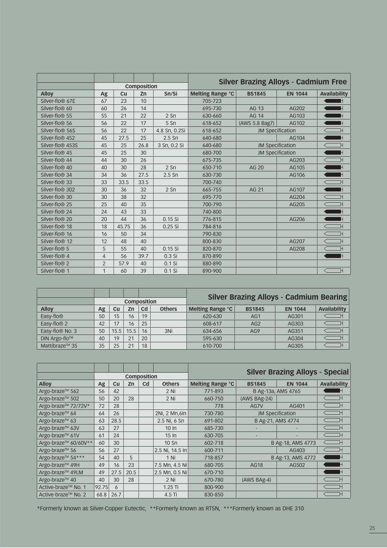
Silver Brazing Alloys - Cadmium FreeComposition
Alloy Ag Cu Zn Sn/Si Melting Range °C BS1845 EN 1044 AvailabilitySilver-flo® 67E 67 23 10 705-723Silver-flo® 60 60 26 14 695-730 AG 13 AG202Silver-flo® 55 55 21 22 2 Sn 630-660 AG 14 AG103Silver-flo® 56 56 22 17 5 Sn 618-652 (AWS 5.8 Bag7) AG102Silver-flo® 56S 56 22 17 4.8 Sn, 0.2Si 618-652 JM SpecificationSilver-flo® 452 45 27.5 25 2.5 Sn 640-680 AG104Silver-flo® 453S 45 25 26.8 3 Sn, 0.2 Si 640-680 JM SpecificationSilver-flo® 45 45 25 30 680-700 JM SpecificationSilver-flo® 44 44 30 26 675-735 AG203Silver-flo® 40 40 30 28 2 Sn 650-710 AG 20 AG105Silver-flo® 34 34 36 27.5 2.5 Sn 630-730 AG106Silver-flo® 33 33 33.5 33.5 700-740Silver-flo® 302 30 36 32 2 Sn 665-755 AG 21 AG107Silver-flo® 30 30 38 32 695-770 AG204Silver-flo® 25 25 40 35 700-790 AG205Silver-flo® 24 24 43 33 740-800Silver-flo® 20 20 44 36 0.15 Si 776-815 AG206Silver-flo® 18 18 45.75 36 0.25 Si 784-816Silver-flo® 16 16 50 34 790-830Silver-flo® 12 12 48 40 800-830 AG207Silver-flo® 5 5 55 40 0.15 Si 820-870 AG208Silver-flo® 4 4 56 39.7 0.3 Si 870-890Silver-flo® 2 2 57.9 40 0.1 Si 880-890Silver-flo® 1 1 60 39 0.1 Si 890-900
Silver Brazing Alloys - Cadmium BearingComposition
Alloy Ag Cu Zn Cd Others Melting Range °C BS1845 EN 1044 AvailabilityEasy-flo® 50 15 16 19 620-630 AG1 AG301Easy-flo® 2 42 17 16 25 608-617 AG2 AG303Easy-flo® No. 3 50 15.5 15.5 16 3Ni 634-656 AG9 AG351DIN Argo-floTM 40 19 21 20 595-630 AG304MattibrazeTM 35 35 25 21 18 610-700 AG305
Silver Brazing Alloys - SpecialComposition
Alloy Ag Cu Zn Cd Others Melting Range °C BS1845 EN 1044 AvailabilityArgo-brazeTM 562 56 42 2 Ni 771-893 B Ag-13a, AMS 4765Argo-brazeTM 502 50 20 28 2 Ni 660-750 (AWS BAg-24)Argo-brazeTM 72/72V* 72 28 778 AG7V AG401Argo-brazeTM 64 64 26 2Ni, 2 Mn,6In 730-780 JM SpecificationArgo-brazeTM 63 63 28.5 2.5 Ni, 6 Sn 691-802 B Ag-21, AMS 4774Argo-brazeTM 63V 63 27 10 In 685-730 - -Argo-brazeTM 61V 61 24 15 In 630-705 - -Argo-brazeTM 60/60V** 60 30 10 Sn 602-718 B Ag-18, AMS 4773Argo-brazeTM 56 56 27 2.5 Ni, 14.5 In 600-711 AG403Argo-brazeTM 54*** 54 40 5 1 Ni 718-857 B Ag-13, AMS 4772Argo-brazeTM 49H 49 16 23 7.5 Mn, 4.5 Ni 680-705 AG18 AG502Argo-brazeTM 49LM 49 27.5 20.5 2.5 Mn, 0.5 Ni 670-710Argo-brazeTM 40 40 30 28 2 Ni 670-780 (AWS BAg-4)Active-brazeTM No. 1 92.75 6 1.25 Ti 800-900Active-brazeTM No. 2 68.8 26.7 4.5 Ti 830-850
*Formerly known as Silver-Copper Eutectic, **Formerly known as RTSN, ***Formerly known as DHE 310
26
Base Metal/Copper Based Brazing AlloysComposition
Alloy Cu Others Melting Range °C BS1845 EN 1044 AvailabilityCopper 99Cu 1081 CU5 CU10194/6 Copper-Tin 94Cu 6Sn 945-1065 - -B BronzeTM 97Cu 3Ni 0.02B 1081-1101 CU7 CU105C BronzeTM 86.5Cu 11Mn 2.5 Ni 965-995 - -D BronzeTM 86Cu 10Mn 4Co 980-1030 - -F BronzeTM 58Cu 2Mn 2Co 38 Zn 890-930 - -ArgentelTM No.1 60Cu 40Zn 0.2Si 875-895 CZ6 CU301ArgentelTM 48Cu 42Zn 10Ni 890-920 CZ8 CU305
Palladium Based Brazing AlloysComposition
Alloy Pd Ag Cu Ni Melting Range °C BS1845 EN 1044 AvailabilityPallabrazeTM 810 5 68.5 26.5 - 807-810 PD1V PD106PallabrazeTM 840 10 67.5 22.5 - 834-840 PD3V PD104PallabrazeTM 850 10 58.5 31.5 - 824-850 PD2V PD105PallabrazeTM 880 15 65 20 - 856-880 PD4V PD103PallabrazeTM 900 20 52 28 - 876-900 PD5V PD102PallabrazeTM 950 25 54 21 - 901-950 PD6V PD101PallabrazeTM 1010 5 95 - - 970-1010 PD7V PD204PallabrazeTM 1090 18 - 82 - 1080-1090 PD8V PD203
Gold Based Brazing AlloysComposition
Alloy Au Cu Ni Others Melting Range °C BS1845 AMS/AWS A5.8 EN 1044 Availability
OrobrazeTM 910 80 19 - 1 Fe 908-910 AU1V - AU101OrobrazeTM 940 62.5 37.5 - - 930-940 AU2V - AU102OrobrazeTM 950 82 - 18 - 950 AU5V 4787/BAu-4 AU105OrobrazeTM 970 50 50 - - 955-970 - - -OrobrazeTM 990 75 - 25 - 950-990 AU6V - AU106OrobrazeTM 998 37.5 62.5 - - 980-998 AU3V BAu-1 AU103OrobrazeTM 1005 35 65 - - 970-1005 - - -OrobrazeTM 1018 30 70 - - 996-1018 AU4V - AU104OrobrazeTM 1030 35 62 3 - 1000-1030 - BAu-3 -OrobrazeTM 1040 70 - - 30 Ag 1030-1040 - - -
Nickel Based Brazing AlloysComposition
Alloy Ni Cr Fe B Others Melting Range °C BS1845 AMS/AWS A5.8 EN 1044 Availability
Nickelbraze HTN1 Bal 14 4.5 3.1 Si 4.5,C 0.7 980-1060 HTN1 4775/BNi-1 NI101Nickelbraze HTN1A Bal 14 4.5 3.1 Si 4.5 980-1070 HTN1A 4776/BNi-1a NI1A1Nickelbraze HTN2 Bal 7 3.0 3.1 Si 4.5 970-1000 HTN2 4777/BNi-2 NI102Nickelbraze HTN3 Bal - 0.5 3.1 Si 4.5 980-1040 HTN3 4778/BNi-3 NI103Nickelbraze HTN4 Bal - 1.5 1.8 Si 3.5 980-1070 HTN4 4779/BNi-4 NI104Nickelbraze HTN5 Bal 19 - - Si 10.1 1080-1135 HTN5 4782/BNi-5 NI105Nickelbraze HTN6 Bal - - - P 11 875 HTN6 BNi-6 NI106Nickelbraze HTN7 Bal 14 - - P 10.1 890 HTN7 BNi-7 NI107
The JM Metal Joining Paste Product Range - Alloy Reference Chart
27
The Environment
The use of lead and cadmium in products is increasingly recognised as being undesirable both in terms of the long-term
environmental impact and recyclability of products.
The End of Life Vehicles (ELV) Directive (2000/53/EC), the RoHS Regulations in Directive (2002/95/EC) and WEEE Directive
on waste electrical and electronic equipment (2002/96/EC) prevent the use of certain hazardous substances including
cadmium and lead containing materials. The use of lead in potable water systems has also been prohibited in Europe and in
many countries worldwide.
Health and Safety in Soldering and Brazing
Soldering and brazing are firmly established throughout the world as reliable, simple and safe methods of joining metal
components. However, as both processes entail the raising of components to elevated temperatures and the use of molten
alloys and chemical fluxes that contain volatile constituents, regard must be paid to safety precautions when soldering
or brazing. Johnson Matthey Metal Joining issue full material safety datasheets and offer general guidelines on health and
safety in soldering or brazing. Please consult the Johnson Matthey Technical Department for advice on health and safety in
soldering or brazing.
Lead and Cadmium Containing Products
Health and safety issues associated with the incorrect use of cadmium containing filler metals and disposal of lead and
cadmium containing products are also widely recognised.
Johnson Matthey recommends cadmium-free and lead-free products wherever possible. Unless a sound technical reason
exists for doing otherwise we will not recommend the use of cadmium or lead containing materials.
Please consult the Johnson Matthey Technical Department for advice on cadmium or lead free products.
The Environment, Health and Safety
Acknowledgments Designed and produced by Graphicworks. Burner & Flame Technology Ltd - Stalybridge and Mr John Levitt for the assistance with the principle photography. Atkinson Walker Saws Ltd. Sheffield, and Armeg Ltd, Dronfield for supplying components for photographic purposes.
NotesJohnson Matthey Plc cannot anticipate all conditions under which this information and our products or the products of other manufacturers in combination with our products will be used.This information relates only to the specific material designated and may not be valid for such material used in combination with any other materials or in any process. Such information is given in good faith, being based on the latest information available to Johnson Matthey Plc and is, to the best of Johnson Matthey Plc’s knowledge and belief, accurate and reliable at the time of preparation. However, no representation, warranty or guarantee is made as to the accuracy or completeness of the information and Johnson Matthey Plc assumes no responsibility therefore and disclaims any liability for any loss, damage or injury howsoever arising (including in respect of any claim brought by any third party) incurred using this information. The product is supplied on the condition that the user accepts responsibility to satisfy himself as to the suitability and completeness of such information for his own particular use. Freedom from patent or any other proprietary rights of any third party must not be assumed.The JM logo©, the Johnson Matthey© name and most product names referred to in these pages are trademarks of the Johnson Matthey Group of companies. The trademarks Easy-flo® and Silver-flo® are registered to the Johnson Matthey Group of companies in the EU. The Sil-fos trademark is registered to JM in the UK and several other countries. However in certain other countries Johnson Matthey market these products using different Trademarks. In particular in the USA Johnson Matthey will use Matti-fos, Mattibraze and Matti-sil and in Germany Matti-fos instead of the aforementioned Tradenames. Information and images contained within this booklet and published by Johnson Matthey Public Limited Company (“Johnson Matthey”) are Copyright and the property of Johnson Matthey. Johnson Matthey authorises you to copy documents or pages published by Johnson Matthey for your non-commercial use only. Copies may be made for others for their personal information only. Any such copy shall retain all copyrights and other Proprietary notices and any disclaimer contained thereon. None of the content of these pages may be incorporated into, reproduced on, or stored in any Web site, electronic retrieval system, or in any other publication, whether in hard copy or electronic form. You may not, without our permission, ‘mirror’ this information, or modify or re-use text or graphics from this booklet.
Johnson Matthey Metal Joining York Way, Royston, Hertfordshire. SG8 5HJ UK
Telephone: +44 (0) 1763 253200 Fax: +44 (0) 1763 253168
Email: [email protected] www.jm-metaljoining.com
Johnson Matthey


