
J. Gerrits FM-UWB Slide 1
John F.M. Gerrits1, John R. Farserotu1, Catherine Dehollain2, Norbert Joehl2, Michel Declercq2.
1Wireless Communications SectionCentre Suisse d’Electronique et de Microtechnique S.A.
2Electronics Laboratory (LEG), EPFL
UWB4SN WorkshopLausanne
4 November 2005
FM-UWB: a constant-envelope UWB communications system for short-range LDR applications

J. Gerrits FM-UWB Slide 2
Motivation for frequency domain approach for low complexity UWB
Since the definition of a UWB signal does not specify a particular
air interface or modulation scheme, many different techniques
may be applicable to a UWB signal.
Pulses that have been optimized for radar-like applications have not necessarily the best characteristics for a communiciations system.
Realization of low power and fully integrated pulse generation circuits is not trivial.
More established modulation schemes may/should be used to generate a UWB signal.

J. Gerrits FM-UWB Slide 3
Short range (1-10m) wireless applications and services for monitoring and control:
Home automationSecurity and alarmsHealth monitoringSports training
These require:
Low cost, low power systemsPortable (ideally go anywhere)Robust and reliableGood coexistence with other RF systemsFast access (short synchronization time)
Applications for LDR FM-UWB
J. Gerrits FM-UWB Slide 4
FM-UWB features
True low complexity system compatible with IC technology Relaxed hardware specs (phase noise, component tolerances) No local oscillator No carrier synchronization CSMA/DAA techniques can enhance performance Antennas are not critical Steep spectral roll-off Robustness to interference and multipath Localization compatibility
A 3 - 5 GHz COTS-based laboratory prototype exists in our labs Key building blocks already available in Si-Ge, down-scaled transmitter under integration in CMOS.
J. Gerrits FM-UWB Slide 5
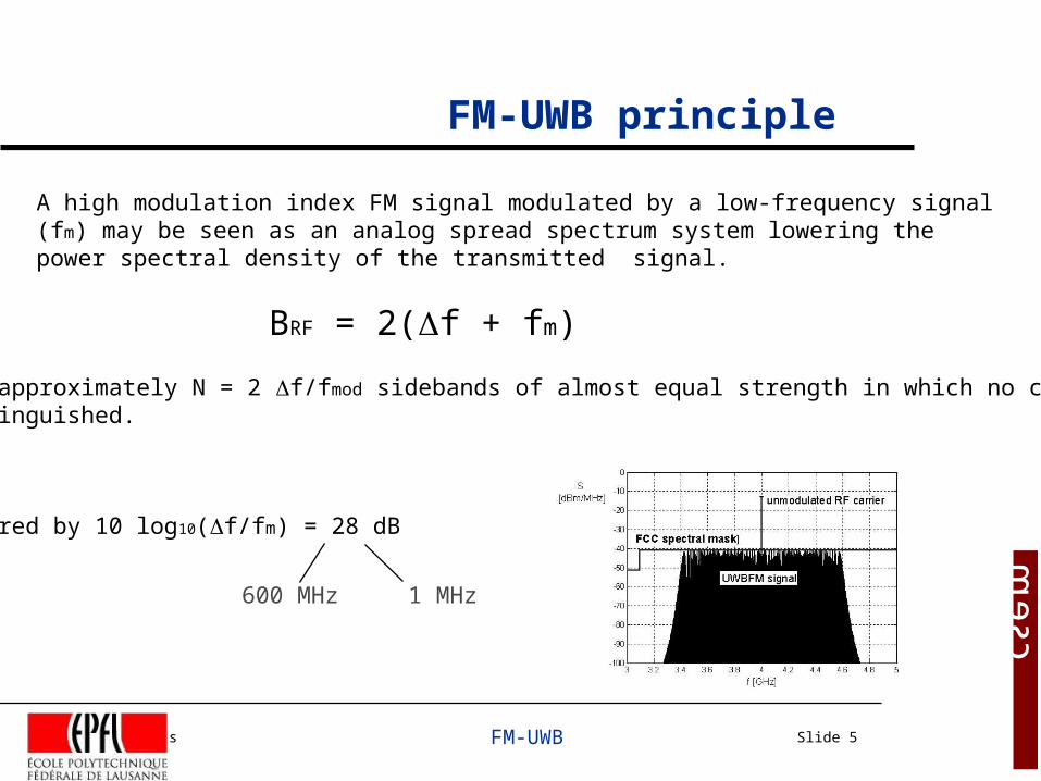
FM-UWB principle
A high modulation index FM signal modulated by a low-frequency signal (fm) may be seen as an analog spread spectrum system lowering the power spectral density of the transmitted signal.
BRF = 2(f + fm)
This gives approximately N = 2 f/fmod sidebands of almost equal strength in which no carrier can be distinguished.
PSD is lowered by 10 log10(f/fm) = 28 dB
600 MHz 1 MHz
J. Gerrits FM-UWB Slide 6
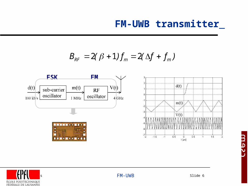
FM-UWB transmitter
FSK FM
)ff(f)(B mmRF 212

J. Gerrits FM-UWB Slide 7
FM-UWB Spectral properties
Good co-existence Best use of spectral mask Dynamic interference mitigation

J. Gerrits FM-UWB Slide 8
FM-UWB receiver

J. Gerrits FM-UWB Slide 9
Wideband FM demodulator
This demodulator has been fully integrated in Si-Ge BiCMOS.
C
21
FMDEMOD f
f
2Ncos
2
AfV

J. Gerrits FM-UWB Slide 10
Measured results
sensitivity: -46 dBm without LNA -68 dBm with 25 dB LNA(5 m in office environment)

J. Gerrits FM-UWB Slide 11
FM-UWB access schemes
A multi-user system may use: FDMA at RF carrier level FDMA at sub-carrier level (TDMA)

J. Gerrits FM-UWB Slide 12
FM sub-carrier techniques
FM-UWB exploits sub-carrier FDMA techniques.Users have their individual subcarrier frequencyand data rate if required.NMAX = 150 @ 1 kbps, NMAX = 15 @ 100 kbps
J. Gerrits FM-UWB Slide 13
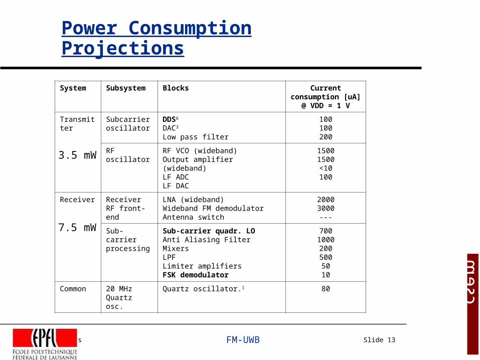
Power Consumption Projections
System Subsystem Blocks Current consumption [uA]
@ VDD = 1 V
Transmitter Subcarrier oscillator
DDS6
DAC3
Low pass filter
100100200
RF oscillator RF VCO (wideband)Output amplifier (wideband)LF ADCLF DAC
15001500<10100
Receiver Receiver RF front-end
LNA (wideband)Wideband FM demodulatorAntenna switch
20003000---
Sub-carrier processing
Sub-carrier quadr. LO Anti Aliasing FilterMixersLPFLimiter amplifiersFSK demodulator
70010002005005010
Common 20 MHz Quartz osc.
Quartz oscillator.1 80
3.5 mW
7.5 mW

J. Gerrits FM-UWB Slide 14
FM-UWB performance in AWGN
Data rate R
[kbit/s]
SNRRF
[dB]
PL
[dB]
dFS
[m]
1 -22 90 183
10 -17 85 106
100 -11 79 52
1000 -5 73 25
processing gain = BRF/BSUB
500 MHz / 2R

J. Gerrits FM-UWB Slide 15
Receiver synchronization time
Raw data right instantaneously, bitsynchronizer limited
J. Gerrits FM-UWB Slide 16
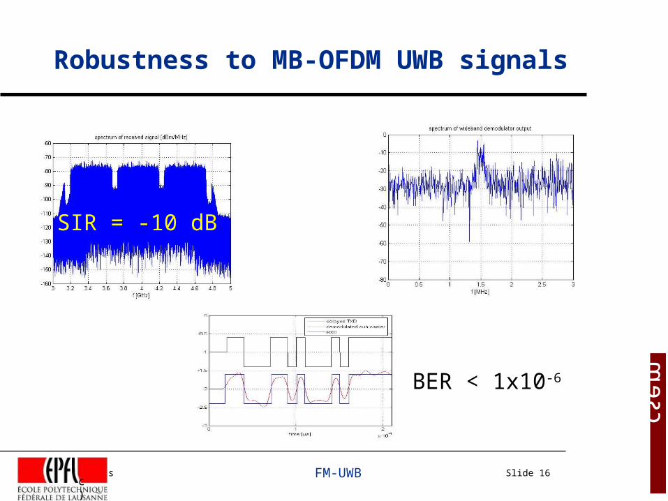
Robustness to MB-OFDM UWB signals
c)
SIR = -10 dB
BER < 1x10⁻⁶

J. Gerrits FM-UWB Slide 17
Which IC technology is required?
A good CMOS or BiCMOS techno (fT = 100 GHz),
low VT and low VDD (1 V),
on-chip passives with moderate Q factor.
Tx Rx
J. Gerrits FM-UWB Slide 18
IC implementation of the FM-UWB Transmitter in 0.18um CMOS Technology
Electronics Laboratory of EPFL
Catherine Dehollain (Speaker)Norbert Joehl and Michel Declercq
([email protected]; Tel: 0041 (0) 21 693 69 71)
J. Gerrits FM-UWB Slide 19
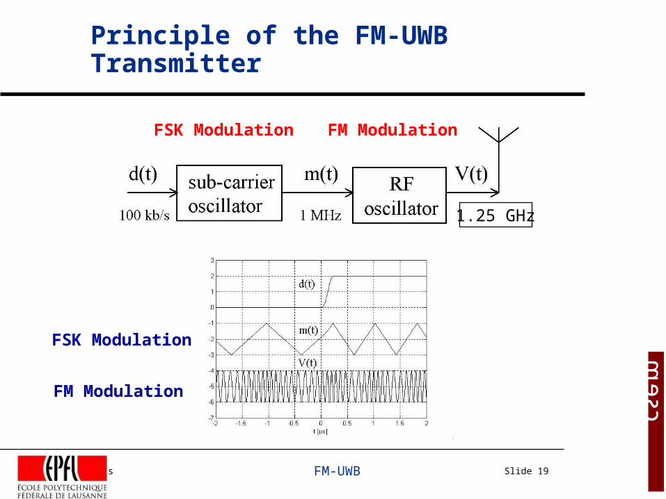
Principle of the FM-UWB Transmitter
1.25 GHz
FSK Modulation FM Modulation
FSK Modulation
FM Modulation
J. Gerrits FM-UWB Slide 20
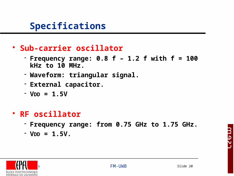
Specifications
Sub-carrier oscillator Frequency range: 0.8 f – 1.2 f with f = 100 kHz to 10 MHz. Waveform: triangular signal. External capacitor. VDD = 1.5V
RF oscillator Frequency range: from 0.75 GHz to 1.75 GHz. VDD = 1.5V.
J. Gerrits FM-UWB Slide 21
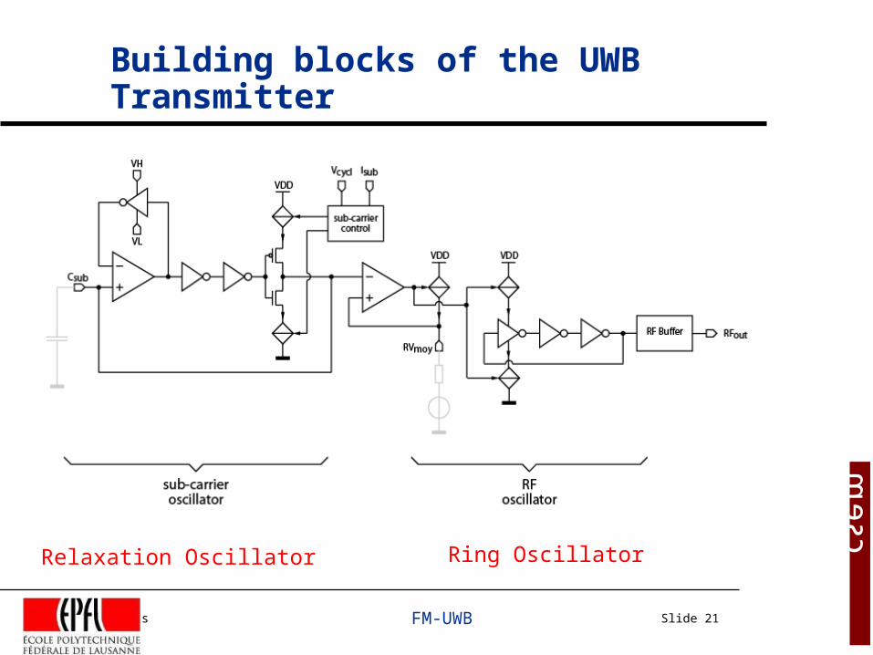
Building blocks of the UWB Transmitter
Relaxation Oscillator Ring Oscillator

J. Gerrits FM-UWB Slide 22
Sub-carrier signal at 80- 120kHz
J. Gerrits FM-UWB Slide 23
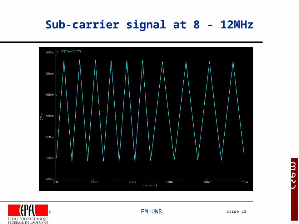
Sub-carrier signal at 8 – 12MHz

J. Gerrits FM-UWB Slide 24
RF signal at 1.25 GHz center frequency
At the output of the integrated circuit
J. Gerrits FM-UWB Slide 25
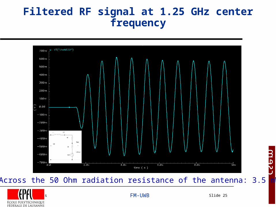
Filtered RF signal at 1.25 GHz center frequency
Across the 50 Ohm radiation resistance of the antenna: 3.5 mW
J. Gerrits FM-UWB Slide 26
Current consumption of the building blocks
Simulation results in UMC 0.18um CMOS with RF options
• VDD = 1.5V.• Sub-carrier oscillator: 0.2 mA.• RF oscillator: 3 mA.• Output buffer: 4 mA.
J. Gerrits FM-UWB Slide 27
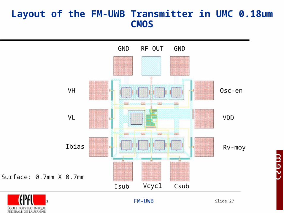
Layout of the FM-UWB Transmitter in UMC 0.18um CMOS
GND RF-OUT GND
VH
VL
Ibias
Osc-en
VDD
Rv-moy
Isub Vcycl Csub
Surface: 0.7mm X 0.7mm
J. Gerrits FM-UWB Slide 28
Next steps
UMC 0.18um CMOS Techno.• Manufacturing of the FM-UWB Transmitter.• Test of the FM-UWB Transmitter.
0.13um CMOS or 0.35 um, 0.25 um BiCMOS SiGe Techno.• Target: the UWB frequency band (3.1 – 10 GHz)• Design of the new FM-UWB Transmitter using:
- Digital sub-carrier generation- 3-5 GHz and 6-9 GHz RF oscillator and output stage


