
3700 Portable SamplersInstruction Manual
Part #60-3703-267 of Assembly #60-3704-101Copyright © 2001. All rights reserved. Isco, Inc.Revision H, February, 2002

3700 Standard and 3700 Compact Sampler
FOREWORD
This instruction manual is designed to help you gain a thorough understanding ofthe operation of the equipment. Isco recommends that you read this manual com-pletely before placing the equipment in service.
Although Isco designs reliability into all equipment, there is always the possibilityof a malfunction. This manual may help in diagnosing and repairing the malfunc-tion.
If the problem persists, call or email the Isco Customer Service Department forassistance. Contact information is provided below. Simple difficulties can often bediagnosed over the phone. If it is necessary to return the equipment to the factoryfor service, please follow the shipping instructions provided by the Customer Ser-vice Department, including the use of the Return Authorization Number speci-fied. Be sure to include a note describing the malfunction. This will aid in theprompt repair and return of the equipment.
Isco welcomes suggestions that would improve the information presented in thismanual or enhance the operation of the equipment itself.
Contact Information
Phone: (800) 228-4373 (USA, Canada, Mexico)(402) 464-0231 (Outside North America)
Fax: (402) 465-3022Email address: [email protected]: www.isco.comReturn equipment to: 4700 Superior Street, Lincoln, NE 68504-1398Other correspondence: P.O. Box 82531, Lincoln, NE 68501-2531
Disclaimers: Although Isco Inc. has made many references to using the sampleroutdoors in this manual, UL (Underwriters Laboratories) has certified these sam-plers for "indoor use only."
Although Isco Inc, has many options for powering the Model 3700 Samplers, UL(Underwriters Laboratories) has certified those samplers for use with the Isco-made 120 VAC High Capacity Power Pack, Model 913 "only."

3700 Standard and 3700 Compact Sampler
3700 Standard and 3700 Compact Sampler
The exclamation point within the triangle is awarning sign alerting you to important instruc-tions in the instrument’s technical referencemanual.
Warnings and Cautions
Ce symbole signale l’existence d’instructionsimportantes relatives au produit dans ce man-uel.
Symboles de sécurité
Das Ausrufezeichen in Dreieck ist ein Warnze-ichen, das Sie darauf aufmerksam macht, daßwichtige Anleitungen zu diesem Handbuchgehören.
Warnungen und Vorsichtshinweise
Esta señal le advierte sobre la importancia delas instrucciones del manual que acompañan aeste producto.
Advertencias y Precauciones
Warning: This instrument has not been certified foruse in "hazardous locations" as defined bythe National Electrical Code.
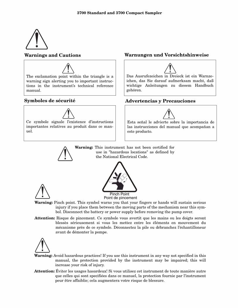
Warning: Pinch point. This symbol warns you that your fingers or hands will sustain seriousinjury if you place them between the moving parts of the mechanism near this sym-bol. Disconnect the battery or power supply before removing the pump cover.
Attention: Risque de pincement. Ce symbole vous avertit que les mains ou les doigts serontblessès sérieusement si vous les mettez entre les éléments en mouvement dumécanisme près de ce symbole. Déconnectez la pile ou débranchez l’échantilloneuravant de démonter la pompe.
Warning: Avoid hazardous practices! If you use this instrument in any way not specified in thismanual, the protection provided by the instrument may be impaired; this willincrease your risk of injury.
Attention: Éviter les usages hasardeux! Si vous utilisez cet instrument de toute manière autreque celles qui sont specifiées dans ce manuel, la protection fournie par l’instrumentpeur être affaiblie; cela augmentera votre risque de blessure.
Pinch PointPoint de pincement

3700 Standard and 3700 Compact Sampler
3700 Standard and 3700 Compact Sampler
i
Table of Contents
Chapter 1. Introduction . . . . . . . . . . . .1Manual Organization. . . . . . . . . . . . . . . . . . . . . . . . . . . . 1Introduction . . . . . . . . . . . . . . . . . . . . . . . . . . . . . . . . . . . 1
3700 Standard Description . . . . . . . . . . . . . . . . . . . . 13700 Compact Description . . . . . . . . . . . . . . . . . . . . . 2
Programmable Features . . . . . . . . . . . . . . . . . . . . . . . . . 2Bottle Configurations . . . . . . . . . . . . . . . . . . . . . . . . . 5Interfacing Equipment. . . . . . . . . . . . . . . . . . . . . . . . 5
Chapter 2. Setup Procedures . . . . . .10Chapter Contents. . . . . . . . . . . . . . . . . . . . . . . . . . . . . . 103700 Sampler Setup Procedures . . . . . . . . . . . . . . . . . . 10Assembly and Disassembly of the Case . . . . . . . . . . . . 10
Preparation of the 3700 Standard Base Section. . . 10Preparation of the 3700 Compact Base Section . . . 10Bottles . . . . . . . . . . . . . . . . . . . . . . . . . . . . . . . . . . . . 10Cooling the Samples. . . . . . . . . . . . . . . . . . . . . . . . . 10Attaching the Suction Line . . . . . . . . . . . . . . . . . . . 11Strainers . . . . . . . . . . . . . . . . . . . . . . . . . . . . . . . . . . 11Connection to Power Source . . . . . . . . . . . . . . . . . . 12Placement of the Sampler . . . . . . . . . . . . . . . . . . . . 12Connection to a Flow Meter or Flow Logger . . . . . . 13
Placing the Sampler into Operation . . . . . . . . . . . . . . . 13Sampler Locking. . . . . . . . . . . . . . . . . . . . . . . . . . . . 14
Chapter 3. Safety Procedures . . . . . .15Important Information . . . . . . . . . . . . . . . . . . . . . . . . . 15General Safety Procedures . . . . . . . . . . . . . . . . . . . . . . 15Lethal Atmospheres in Sewers . . . . . . . . . . . . . . . . . . . 16
Chapter 4. Programming Guidelines . . . . . . . . . . . . . . . . . . . .20
Introduction . . . . . . . . . . . . . . . . . . . . . . . . . . . . . . . . . . 20Description of Sampling Operations . . . . . . . . . . . . . . . 20
Sample Events and the Sampling Cycle . . . . . . . . . 20Types of Samples . . . . . . . . . . . . . . . . . . . . . . . . . . . . . . 21
Types of Sampling Available Through the Extended Programming Mode. . . . . . . . . . . . . . . . . . . . . . . 22
STORM Programming . . . . . . . . . . . . . . . . . . . . . . . . . . 23Programming Introduction . . . . . . . . . . . . . . . . . . . . . . 24
Operating States . . . . . . . . . . . . . . . . . . . . . . . . . . . 24Programming Modes . . . . . . . . . . . . . . . . . . . . . . . . 24Configure Sequence . . . . . . . . . . . . . . . . . . . . . . . . . 27
Introduction to the Programming Procedure . . . . . . . . 27Using the Keypad to Respond to Displays . . . . . . . 27Keypad Description . . . . . . . . . . . . . . . . . . . . . . . . . 28Displays. . . . . . . . . . . . . . . . . . . . . . . . . . . . . . . . . . . 29
Configure Sequence . . . . . . . . . . . . . . . . . . . . . . . . . . . . 50Set Clock . . . . . . . . . . . . . . . . . . . . . . . . . . . . . . . . . . 50Bottles and Sizes . . . . . . . . . . . . . . . . . . . . . . . . . . . 50Suction Line . . . . . . . . . . . . . . . . . . . . . . . . . . . . . . . 51Liquid Detector. . . . . . . . . . . . . . . . . . . . . . . . . . . . . 51Programming Mode . . . . . . . . . . . . . . . . . . . . . . . . . 52Load Stored Program . . . . . . . . . . . . . . . . . . . . . . . . 55Save Current Program . . . . . . . . . . . . . . . . . . . . . . . 56Flow-Mode Sampling . . . . . . . . . . . . . . . . . . . . . . . . 57
Nonuniform Time . . . . . . . . . . . . . . . . . . . . . . . . . . .57Calibrate Sampler . . . . . . . . . . . . . . . . . . . . . . . . . . .57Sampling Stop/Resume. . . . . . . . . . . . . . . . . . . . . . .57Start Time Delay. . . . . . . . . . . . . . . . . . . . . . . . . . . .58Enable Pin . . . . . . . . . . . . . . . . . . . . . . . . . . . . . . . . .58Event Mark . . . . . . . . . . . . . . . . . . . . . . . . . . . . . . . .59Purge Counts. . . . . . . . . . . . . . . . . . . . . . . . . . . . . . .59Tubing Life . . . . . . . . . . . . . . . . . . . . . . . . . . . . . . . .59Program Lock . . . . . . . . . . . . . . . . . . . . . . . . . . . . . .61Sampler ID . . . . . . . . . . . . . . . . . . . . . . . . . . . . . . . .61Run Diagnostics . . . . . . . . . . . . . . . . . . . . . . . . . . . .61Exit Configuration . . . . . . . . . . . . . . . . . . . . . . . . . .61Extended Programming Mode . . . . . . . . . . . . . . . . .64Extended Mode Sample Pacing . . . . . . . . . . . . . . . .65Extended Mode Sample Distribution. . . . . . . . . . . .65Extended Mode Sample Volumes. . . . . . . . . . . . . . .65Extended Mode Key Times . . . . . . . . . . . . . . . . . . . .65Start Times . . . . . . . . . . . . . . . . . . . . . . . . . . . . . . . .69
Storm Programming . . . . . . . . . . . . . . . . . . . . . . . . . . . .73Storm Sampling Checklist . . . . . . . . . . . . . . . . . . . .73
Programming the Sampler for a Storm Routine. . . . . .76Programming Examples. . . . . . . . . . . . . . . . . . . . . . . . .80
Foreign Languages and Metric Units of Measure. .81Standby State . . . . . . . . . . . . . . . . . . . . . . . . . . . . . . . .100Display Status. . . . . . . . . . . . . . . . . . . . . . . . . . . . . . . .104
Source of Sample Event . . . . . . . . . . . . . . . . . . . . .106Error Messages and Missed Samples . . . . . . . . . .106
Run State . . . . . . . . . . . . . . . . . . . . . . . . . . . . . . . . . . .107
Chapter 5. Options and Interfacing Equipment. . . . . . . . . . . . . . . . . . .110
Introduction . . . . . . . . . . . . . . . . . . . . . . . . . . . . . . . . .110Standard Sample Bottle Tub . . . . . . . . . . . . . . . . . . . .110Optional Composite Tub. . . . . . . . . . . . . . . . . . . . . . . .110Programming and Configuring the Controller for
Composite Sampling . . . . . . . . . . . . . . . . . . . . . .111Connections to External Devices . . . . . . . . . . . . . . . . .111
Isco Flow Meters and Flow Loggers. . . . . . . . . . . .112Non-Isco Flow Meters . . . . . . . . . . . . . . . . . . . . . . .112Interface Devices . . . . . . . . . . . . . . . . . . . . . . . . . . .112Master/Slave Connections . . . . . . . . . . . . . . . . . . .112Model 1640 Liquid Level Actuator . . . . . . . . . . . . .113Model 583 Field Computer . . . . . . . . . . . . . . . . . . .113
Chapter 6. Routine Maintenance. .115Introduction . . . . . . . . . . . . . . . . . . . . . . . . . . . . . . . . .115Cleaning the Sampler. . . . . . . . . . . . . . . . . . . . . . . . . .115Cleaning Protocols for Priority Pollutants . . . . . . . . .115Replacement of Pump Tubing . . . . . . . . . . . . . . . . . . .116
Removing the Pump Tubing . . . . . . . . . . . . . . . . . .116Installing a New Pump Tube . . . . . . . . . . . . . . . . .119
Replacement of Suction Line . . . . . . . . . . . . . . . . . . . .119Vinyl Suction Line. . . . . . . . . . . . . . . . . . . . . . . . . .119Teflon Suction Line . . . . . . . . . . . . . . . . . . . . . . . . .120
Changing the Internal Desiccant. . . . . . . . . . . . . . . . .120
Chapter 7. Servicing. . . . . . . . . . . . .122Introduction . . . . . . . . . . . . . . . . . . . . . . . . . . . . . . . . .122Servicing the Controller . . . . . . . . . . . . . . . . . . . . . . . .122

3700 Standard and 3700 Compact Sampler
ii
Removal of the Control Box . . . . . . . . . . . . . . . . . . 122Access to Electronic Components . . . . . . . . . . . . . 122Removal of the Distributor Gear Case Assembly . 125Removal of the Pump Gear Case Assembly . . . . . 125
Precautions for Servicing CMOS Circuitry . . . . . . . . 125Preliminary Electronics Troubleshooting Steps. . . . . 127
Circuit Boards. . . . . . . . . . . . . . . . . . . . . . . . . . . . . 127Sample Event Cycle and Delivery of Sample
Volumes . . . . . . . . . . . . . . . . . . . . . . . . . . . . . . . . 132Replacement Parts List . . . . . . . . . . . . . . . . . . . . . . . . 132Accessory Parts List. . . . . . . . . . . . . . . . . . . . . . . . . . . 132Accessories List for 3700 Portable Samplers . . . . . . . 148
General Accessories . . . . . . . . . . . . . . . . . . . . . . . . 148Bottles, Caps, and Retaining Rings. . . . . . . . . . . . 148Suction Lines and Strainers . . . . . . . . . . . . . . . . . 148Power Sources. . . . . . . . . . . . . . . . . . . . . . . . . . . . . 149Interfacing Equipment. . . . . . . . . . . . . . . . . . . . . . 149
List of Figures
1. Technical Specifications of the 3700 Standard Sampler. . . . . . . . . . . . . . . . . . . . . . . . . . . . . . . . . . 7
2. Technical Specifications of the 3700 Compact Sample . . . . . . . . . . . . . . . . . . . . . . . . . . . . . . . . . . 8
3. Hazardous Gases . . . . . . . . . . . . . . . . . . . . . . . . . . . . 184. Configure Option Functions . . . . . . . . . . . . . . . . . . . 265. Bottle Volume Settings for Standard Bottle
Configurations . . . . . . . . . . . . . . . . . . . . . . . . . . . 516. Sampling capabilities through the Program
Sequence . . . . . . . . . . . . . . . . . . . . . . . . . . . . . . . . 537. Factory Configure Option settings . . . . . . . . . . . . . . 628. Factory Program settings . . . . . . . . . . . . . . . . . . . . . 639. Start Time Displays. . . . . . . . . . . . . . . . . . . . . . . . . . 7010. Recommended configuration settings for
storm sampling. . . . . . . . . . . . . . . . . . . . . . . . . . . 7411. Flow Meter Connector Wiring. . . . . . . . . . . . . . . . 11212. Printer Connector Wiring . . . . . . . . . . . . . . . . . . . 11213. Display Index . . . . . . . . . . . . . . . . . . . . . . . . . . . . . 150
List of Tables
1. Technical Specifications of the 3700 Standard Sampler . . . . . . . . . . . . . . . . . . . . . . . . . . . . . . . . . .7
2. Technical Specifications of the 3700 Compact Sample . . . . . . . . . . . . . . . . . . . . . . . . . . . . . . . . . . .8
3. Hazardous Gases . . . . . . . . . . . . . . . . . . . . . . . . . . . .184. Configure Option Functions. . . . . . . . . . . . . . . . . . . .265. Bottle Volume Settings for Standard Bottle
Configurations. . . . . . . . . . . . . . . . . . . . . . . . . . . .516. Sampling capabilities through the Program
Sequence . . . . . . . . . . . . . . . . . . . . . . . . . . . . . . . .537. Factory Configure Option settings . . . . . . . . . . . . . .628. Factory Program settings. . . . . . . . . . . . . . . . . . . . . .639. Start Time Displays . . . . . . . . . . . . . . . . . . . . . . . . . .7010. Recommended configuration settings for
storm sampling.. . . . . . . . . . . . . . . . . . . . . . . . . . .7411. Flow Meter Connector Wiring . . . . . . . . . . . . . . . .11212. Printer Connector Wiring. . . . . . . . . . . . . . . . . . . .11213. Display Index . . . . . . . . . . . . . . . . . . . . . . . . . . . . .150
3700 Standard and 3700 Compact Sampler
iii
List of Examples
1. Checking the configure option settings. . . . . . . . . . . 332. Time-paced sequential sampling. . . . . . . . . . . . . . . . 363. Flow-paced sequential sampling. . . . . . . . . . . . . . . . 384. Time-paced multiplexed (samples-per-bottle)
sampling.. . . . . . . . . . . . . . . . . . . . . . . . . . . . . . . . 405. Flow-paced multiplexed (samples-per-bottle)
sampling.. . . . . . . . . . . . . . . . . . . . . . . . . . . . . . . . 436. Time-paced composite sampling. . . . . . . . . . . . . . . . 457. Calibration . . . . . . . . . . . . . . . . . . . . . . . . . . . . . . . . . 498. Load Stored Program. . . . . . . . . . . . . . . . . . . . . . . . . 559. Save Current Program. . . . . . . . . . . . . . . . . . . . . . . . 5610. Time-paced sampling – Uniform time intervals . . 8211. Time-paced multiplexed (samples-per-bottle)
sampling.. . . . . . . . . . . . . . . . . . . . . . . . . . . . . . . . 8412. Extended flow-paced multiplexed (bottles-per-
sample) sampling . . . . . . . . . . . . . . . . . . . . . . . . . 8613. Flow-paced sampling with bottle sets based on
time. . . . . . . . . . . . . . . . . . . . . . . . . . . . . . . . . . . . 8814. Time-paced samples at nonuniform time
intervals. . . . . . . . . . . . . . . . . . . . . . . . . . . . . . . . 9115. Time-paced samples at nonuniform clock times . . 9416. Sampling with stops and resumes. . . . . . . . . . . . . . 9517. Storm Sampling. . . . . . . . . . . . . . . . . . . . . . . . . . . . 9818. Program started later than programmed start
time. . . . . . . . . . . . . . . . . . . . . . . . . . . . . . . . . . . 10219. Program started later than programmed first
switch time.. . . . . . . . . . . . . . . . . . . . . . . . . . . . . 10220. Program started later than programmed stop
time. . . . . . . . . . . . . . . . . . . . . . . . . . . . . . . . . . . 10321. Reviewing the sampling results. . . . . . . . . . . . . . . 10522. Run State Displays – Time-paced sampling. . . . . 10723. Run State Displays – Flow-paced sampling. . . . . 10824. Run State Displays – Composite sampling. . . . . . 109

3700 Standard and 3700 Compact Sampler
iv
3700 Standard and 3700 Compact Sampler
1
Chapter 1 IntroductionManual Organization
This manual explains the features of Isco’s 3700Portable Samplers, the 3700 Standard and 3700Compact, and includes instructions for operation,programming, and maintenance.
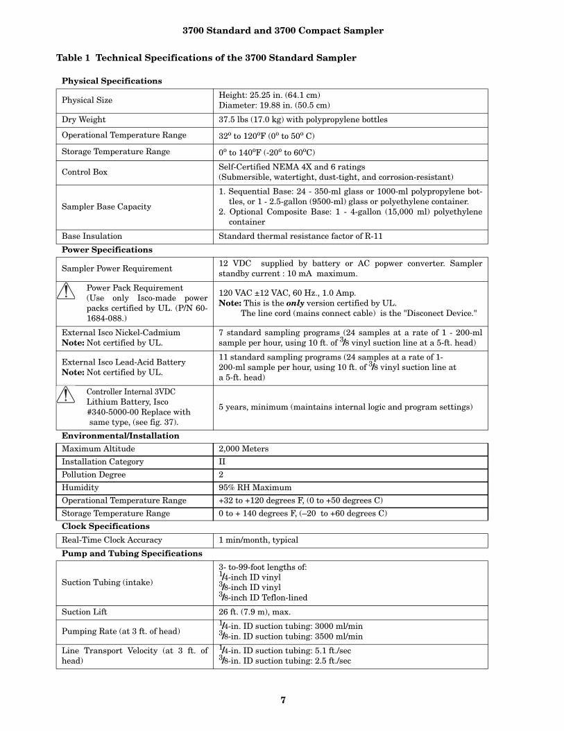
Chapter 1 - contains a summary of the samplers’capabilities and features. It notes key accessories.Table 1 lists the technical specifications for the3700 Standard and Table 2 lists the specificationsfor the 3700 Compact.
Chapter 2 - tells how to install the sampler.
Chapter 3 - covers important safety consider-ations for those who must install a sampler in haz-ardous environments.
Chapter 4 - details how to program your Standardor Compact sampler. The chapter includes sectionsthat summarize keypad functions, programmingfeatures, basic sequential and composite program-ming routines, setup options, and more sophisti-cated programming routines.
Chapter 5 - provides information about sampleroptions and accessories. It contains instructions forconverting your sampler to a single-bottle compos-ite sampler, and for connecting it to Isco and non-Isco flow meters and other related interfaces.
Chapter 6 - describes basic maintenance operations,including cleaning procedures, suction line and pumptubing replacement, and battery maintenance.
Chapter 7 - contains servicing information for thesampler and discusses removal and disassembly ofthe control box, removal of the pump and distribu-tor-gear case, and care of CMOS circuitry.
Appendix A - Replacement Parts Listing con-tains an illustrated parts breakdown.
Appendix B - Accessories lists accessory compo-nents for the Isco 3700 Sampler.
Appendix C - Display Index- briefly discussesthe displays used to program the sampler. Inputdisplays are listed numerically; a brief explanationaccompanies each listed display.
Appendix D - Calculating Flow IncrementBetween Samples demonstrates the calculationsneeded to estimate the flow increment betweensamples.
Appendix E - Glossary a list of terms unique tothis manual.
Appendix F - Material Safety Data Sheets.
Introduction The 3700 Standard Portable Sampler is a program-mable liquid sampler and is one of Isco’s 3700Series of portable and refrigerated samplers. Theextensive sampling capabilities; easy, flexible pro-gramming, and durable construction make the3700 Series ideally suited for general-purpose orpriority-pollutant sampling. The 3700 samplersalso provide storm-paced sampling capabilitiesdesigned to meet the EPA requirements for stormwater runoff monitoring.
The newest member of Isco’s 3700 Portable family,the 3700 Compact is a smaller version of the 3700Standard. It has the same sampling capabilities,flexible programming, and rugged construction ofthe larger 3700s, but is lightweight. A new featureof the 3700 Compact is a removable inner sleeve tohold the bottles. Previously, users who wanted mul-tiple-bottle configurations had to purchase differentbases; with the 3700 Compact, they merely removethe inner sleeve and change bottle configurations.
The entire 3700 family offers a number of verysophisticated features. The following sections pro-vide an overview of the standard and compactunits’ sampling capabilities and a variety of inter-facing equipment. The end of this chapter providesa brief discussion of this interfacing equipment,which includes:
• Isco 3200 and 4200 Series Flow Meters and4100 Series Flow Loggers (collectively called“flow meters” throughout this manual) forflow-weighted sampling and sampler-enablecontrol;
• Isco Field Printers that print the sampler’sprogram settings and sampling results;
• Laptop computers that collect, store, or trans-fer the same data from a sampler in the field toa computer in the office;
• Model 583 Field Computer, which is a durable,lightweight alternative to a laptop.
3700 Standard Description
The 3700 Standard is designed for operation in hos-tile environments, such as sanitary sewers, withoutadditional protection. The gray acrylonitrile-butadi-ene-styrene (ABS) plastic used in the basic construc-tion of the exterior exhibits good resistance toaqueous solutions containing common acids andbases. All of the other external components are madeof either stainless steel, anodized aluminum,polypropylene, Noryl, or EPDM.
3700 Standard and 3700 Compact Sampler
2
The 3700 Standard consists of three units: the topcover, the center section, and the base section. Theremovable cover protects the control box mountedon the center section. The center section includesthe control box, liquid detector, pump, and distri-bution system. A desiccator is installed in the control box to pre-vent moisture damage to the electronics, pump,and distributor systems. The sample base holdsthe sequential or composite bottles and is fullyinsulated, allowing you to ice down samples tomaintain sample integrity. A watertight control box mounted on the top of thecenter section houses the controller. The controllerconsists of a microprocessor with software embed-ded in a PROM (Programmable Read-Only Mem-ory) and supporting electronics. The controllerruns the pump, moves the distributor, responds tothe keypad, and presents information on the dis-play. The controller provides for manual control ofthe sampler; for example, you can run the pumpforward with the pump forward key or initiate amanual sample with the manual sample key. Itgoverns all automatic sampling according to user-selectable program settings.
CAUTION
Tests indicate that the pump produces sound levels inexcess of 85db at one meter. Prolonged exposure tothis sound level could result in hearing loss and re-quires the use of protective ear plugs.
The control panel, which has a 40-character alpha-numeric Liquid Crystal Display (LCD) and keypad,is located on the top of the control box. The 24-posi-tion keypad is used to enter program parametersand direct the following controls: on/off, pumpreverse, pump forward, stop the pump, start sam-pling, resume sampling, display the operating sta-tus, and move the distributor arm to the next bottle.
3700 Compact DescriptionThe 3700 Compact is a modular system that is cus-tom-configured for the user. It includes a universalcompact insulated base, the inner sleeve with achoice of five bottle configurations, the standard3700 controller, and a top cover. The externalcomponent materials, control panel, display, andkeypad are the same as that of the 3700 Portable.
The 3700 Compact is designed for durability andcarrying ease. In addition its sturdy latches andhandles, the base section of the unit has fingergrips molded into the plastic to make it easier tocarry. At its heaviest — with 24-bottle sleeve inside— the unit weighs only 62 pounds.
Programmable FeaturesAn intuitive user interface lets you easily programthe 3700s for both simple and complex samplingschemes. The LCD prompts you through the pro-gramming process by presenting a choice or aquestion on the LCD.
To program the 3700s, you merely respond to dis-played prompts with the keypad. Two program-ming modes, “basic” and “extended," are standardwith the 3700 Series.
The basic programming mode allows you to set uptypical sampling routines easily and efficiently.The extended programming mode expands the ver-satility of the sampler by providing options that letyou create complex sampling routines.
The LCD not only prompts you through the pro-gramming process, but also allows you to closelymonitor a sampling routine as it is executed. TheLCD shows pertinent information about the rou-tine – for example, the time of the next sample andnotifies you of any problems encountered duringthe routine. As the routine progresses, the samplerlogs (stores) key information about the results ofthe routine. The results include the start time, anyhalt and resume times, time of samples, and causeof any missed samples. This information is accessi-ble during a routine or after a sampling routine isfinished. You can view this information from thesampler’s display or retrieve the information withthe field printer or a laptop computer runningIsco’s SAMPLINK® software.
Flexible Sampling Intervals - The 3700s aredesigned to collect as many as 24 separate sequen-tial (discrete) samples and are fully programmablefor true composite sampling. You can collect bothsequential and composite samples at user-defin-able time intervals (time-pacing) or at equal flow-volume intervals using flow pulse inputs from anexternal flow meter (flow-pacing). You can set theflow interval from 1 to 9,999 flow pulses.
Both samplers offer two types of time-pacing: uni-form and nonuniform. You can take uniform time-paced samples at regular time intervals-a sampleevery 15 minutes, for example. You can set theinterval between samples from 1 minute to 99hours, 59 minutes in 1-minute increments. Usingthe extended programming mode, you can specifyas many as 999 (or bottle-volume dependent) non-uniform time intervals in minutes. For example,you can program the sampler to take the first sixsamples at 10-minute intervals, then four moresamples at 15-minute intervals, and so on. Userscan set nonuniform time intervals from 1 to 999minutes in 1-minute intervals. You can specify

3700 Standard and 3700 Compact Sampler
3
nonuniform times in a clock-time format by enter-ing a time and date for each sample. The samplerwill accept as many as 99 nonuniform clock times.
Additionally, the Sampling Stop-and-Resume fea-ture allows you to create an intermittent samplingschedule. With this extended programming fea-ture, you can sample only during key periods of theday. For example, you may wish to sample onlyduring the hours of 6 AM to 8 AM, and 5 PM to 7PM. You can enter as many as 12 sampling stopsand 12 resumes. You can use sampling stops andresumes with both flow- and time-paced routinesand with uniform and nonuniform time intervals.
Multiplexing - In addition to sequential sam-pling, which places one sample in each bottle, thesampler provides three standard types of multi-plexed sample distribution: samples-per-bottlemultiplexing, bottles-per-sample multiplexing, andmultiple-bottle compositing.
In samples-per-bottle multiplexing, more than onesample volume can be placed in a bottle. Samples-per-bottle multiplexing allows you to collect aseries of small composite samples.
If you deposit several samples in each bottle, thecontents represent an average of the flow streamduring the sampling period. In bottles-per-samplemultiplexing, you can place equal sample volumesin as many as 24 bottles at each sample event. Bot-tles-per-sample multiplexing is ideal for situationswhere you need identical sets of samples – whenyou need to use more than one preservative, forexample. You can multiplex both time-paced andflow-paced sequential samples.
The third type of multiplexing, multiple-bottlecompositing, is accessible through the extendedprogramming mode. Multiple-bottle compositingplaces more than one sample volume into morethan one bottle. At each sample event, a samplevolume is placed in several bottles, in sets of asmany as 24 bottles. Multiple-bottle compositingcombines bottles-per-samples multiplexing andsamples-per-bottle multiplexing; it is applicable tosituations where you need a series of identical setsof samples. You can also use multiple bottle com-positing when you need a series of larger volumecomposite samples by taking several smaller sam-ples and distributing them over several bottles.
In the extended programming mode, you canswitch multiplexed bottles or bottle sets after aprogrammed number of samples have been depos-ited or after a programmed period of time. Bothmethods can be used with either time-paced orflow-paced routines. By specifying the number ofsamples to be deposited, you can control the vol-
ume of each bottle precisely. By specifying that thesets be switched after specific time periods, youcan control the time frame for a series of samplevolumes. This is especially useful for flow-pacedsampling. Although the flow rate may vary, eachbottle or bottle set represents a fixed time period.
STORM Sampling - The 3700 Series storm capa-bilities are ideal for monitoring storm water runoff.The sampler allows you to divide the bottles intotwo groups. The first group of bottles is normallyreserved for a first-flush grab sample. The secondbottle group receives the flow-weighted compositesamples. You can distribute samples in either groupsequentially or in any of the three types of multi-plexing. Three bottle configurations are availablefor STORM sampling with the 3700 Standard are:the 24-bottle configuration with either 1,000 or 350ml bottles, a 12-bottle configuration containing 1quart (950 ml) glass bottles, and a 4-bottle configu-ration with 1-gallon (3,800 ml) glass bottles. Withthe 3700 Compact, 24-bottle sets have a capacity of500 ml and 12-bottle sets have a 300 ml capacity.
STORM sampling takes full advantage of the sam-pler-enable programming available through theIsco 3200 and 4200 Series Flow Meters, or the4100 Series Flow Logger and the FLOWLINK®
software. You can program the flow meter to moni-tor the flow stream for “storm” conditions- a spe-cific amount of rainfall, for example - and enablethe sampler when it detects those conditions.
Master/Slave Sampling - A notable feature is themaster/slave setting, which allows you to operate two3700 Samplers as a master/slave pair. Master/slavesampler pairing doubles the capacity of a samplinginstallation and to perform continuous sampling.
Two samplers can be connected so that one sam-pler (the master) inhibits the operation of the sec-ond sampler (the slave) until the master completesits sampling routine. The samplers then reverseroles. You can service a full sampler while its coun-terpart is running a routine. In some applications,master/slave pairs can reduce the number of visitsto an installation. A reduced number of visits isimportant when considering the costs and safety ofa sampling study.
STORM Sampling - The 3700 Sampler provides aSTORM variant of master/slave sampling. InSTORM sampling, the master sampler enables theslave sampler when the master sampler completesits STORM routine. The slave sampler then com-pletes its routine but does not enable the first sam-pler at the end of the slave routine. The slave’sroutine is normally a flow-paced a routine, notanother STORM routine. The STORM variant of

3700 Standard and 3700 Compact Sampler
4
master/slave sampling allows you to both increasethe total volume of samples collected and extendthe sampling time period.
Accurate Sample Volumes - You can programthe sampler to take sample volumes of 10 to 9,990milliliters. Equipped with the LD90 liquid pres-ence detector, the 3700s deliver accurate, repeat-able sample volumes in changing head conditions.The LD90 is a nonwetted liquid-presence detector.It detects virtually any pumpable liquid, and,because it is nonwetted, sample conductivity, vis-cosity, temperature, and composition do not affectdetection. Although it is not normally necessary,you can calibrate samples if you wish.
Flexible Start Times - You can program a sam-pling routine to use a specific start time and dateor a start time delay. The sampler will accept a spe-cific start time and date up to one month beyondthe current date. The start-time delay is the periodbetween the time you press the start sampling keyand the time the routine actually starts. You canadjust it from 0 (zero) to 9,999 minutes.
Other features are available. Program storageallows you to store as many as three separate pro-grams, eliminating the need to reprogram the sam-pler for recurrent sampling routines. A programlock prevents unauthorized program alterations.When the lock is enabled, users must enter a pass-word before they can change any program settings,although they can view the programed settings atany time.
Foreign Languages and Metric Units of Mea-sure - The 3700 Series samplers provide displaysin French, German, and Spanish. Additionally, thesoftware supports entries in metric units of mea-sure. Samplers using French and German lan-guage displays support metric units for suction-line and suction-head measurements. Metric unitsinclude volumes in milliliters, suction-head andsuction-line length in decimeters, and suction-lineinside diameter (ID) in millimeters.
Samplers with English displays support eitherEnglish or metric units for suction-line and suc-tion-head measurements. (Sample volume unitsare always entered in milliliters, regardless of theselected language.)
Delivery System - The 3700 Series uses a peri-staltic pump for sample collection. The sample isunder pumped flow at all times; there are nometering chambers and no gravity-fed internaltubing. Each sampling cycle includes an air pre-sample purge and post-sample purge to clear thesuction line both before and after sampling. Thesefeatures make the 3700s ideal for both “suspended
solid” and “toxic material” sampling. Cross con-tamination between samples is minimized, andsites for sediment accumulation in the system areeliminated. Materials in contact with the samplefluid are limited to the strainer, suction line, pumptubing, and collection bottles. You can easily andsafely clean the system by replacing relativelyinexpensive lengths of tubing.
Pump speed is approximately 250 RPM, whichgenerates a velocity sufficient to obtain represen-tative samples. The pumping rate of 3,500 ml perminute is generated when using 3/8-inch ID suctionline at 3 feet of head. The line transport velocity,using the same suction line and head, is 2.5 feetper second. Pump speed does not significantlyaffect volumetric accuracy because the deliveredvolume is based on a patented electronic count ofthe number of pump revolutions.
Liquid Detector - The LD90 gives the 3700s theability to deliver accurate, repeatable sample vol-umes regardless of changing head conditions. Typi-cal sample volumes are accurate to within 10% ofthe programmed volume and repeatable to within± 10 ml. When concerns of cross-contaminationarise, the detector and a programmable settingprovide for automatic rinsing of the suction line. Aprogrammable setting for sampling retries is avail-able. If the suction line becomes clogged and no liq-uid is detected in the line, you can program thesampler to repeat a purge cycle – as many as threetimes – to clear the clogged line.
Pump Tubing and Suction Lines - The pumptubing is Silastic-medical grade silicon rubber. Liq-uid is transferred from the source to the pumpthrough either 1/4- or 3/8-inch ID vinyl or 3/8-inch IDTeflon suction tubing. You can easily replace thepump tubing and suction lines, minimizing theneed for cleaning. The sampler automatically mon-itors pump tubing wear: A tubing warning indica-tion appears when the pump-revolution countexceeds a user-specified wear limit.
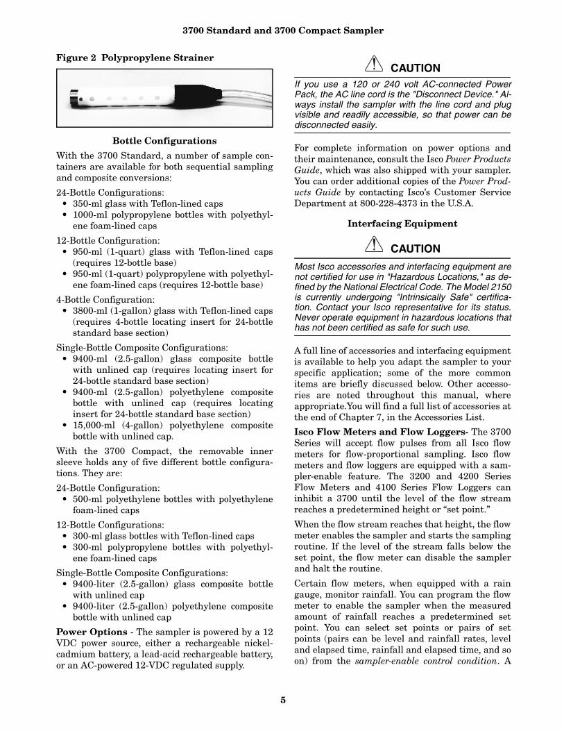
Strainers - Isco offers two stainless steel strainers(Figure 1) for priority pollutant applications: alarger unit for normal flow and a smaller unit forlow-flow situations. An all-plastic strainer is avail-able for sampling from highly acidic flow streams.For general-purpose applications, Isco recommendsa weighted polypropylene strainer (Figure 2). Figure 1 Stainless Steel Strainer
3700 Standard and 3700 Compact Sampler
5
Figure 2 Polypropylene Strainer
Bottle Configurations
With the 3700 Standard, a number of sample con-tainers are available for both sequential samplingand composite conversions:
24-Bottle Configurations:• 350-ml glass with Teflon-lined caps• 1000-ml polypropylene bottles with polyethyl-
ene foam-lined caps
12-Bottle Configuration:• 950-ml (1-quart) glass with Teflon-lined caps
(requires 12-bottle base) • 950-ml (1-quart) polypropylene with polyethyl-
ene foam-lined caps (requires 12-bottle base)
4-Bottle Configuration: • 3800-ml (1-gallon) glass with Teflon-lined caps
(requires 4-bottle locating insert for 24-bottlestandard base section)
Single-Bottle Composite Configurations:• 9400-ml (2.5-gallon) glass composite bottle
with unlined cap (requires locating insert for24-bottle standard base section)
• 9400-ml (2.5-gallon) polyethylene compositebottle with unlined cap (requires locatinginsert for 24-bottle standard base section)
• 15,000-ml (4-gallon) polyethylene compositebottle with unlined cap.
With the 3700 Compact, the removable innersleeve holds any of five different bottle configura-tions. They are:
24-Bottle Configuration:• 500-ml polyethylene bottles with polyethylene
foam-lined caps
12-Bottle Configurations:• 300-ml glass bottles with Teflon-lined caps• 300-ml polypropylene bottles with polyethyl-
ene foam-lined caps
Single-Bottle Composite Configurations:• 9400-liter (2.5-gallon) glass composite bottle
with unlined cap• 9400-liter (2.5-gallon) polyethylene composite
bottle with unlined cap
Power Options - The sampler is powered by a 12VDC power source, either a rechargeable nickel-cadmium battery, a lead-acid rechargeable battery,or an AC-powered 12-VDC regulated supply.
CAUTIONIf you use a 120 or 240 volt AC-connected PowerPack, the AC line cord is the "Disconnect Device." Al-ways install the sampler with the line cord and plugvisible and readily accessible, so that power can bedisconnected easily.
For complete information on power options andtheir maintenance, consult the Isco Power ProductsGuide, which was also shipped with your sampler.You can order additional copies of the Power Prod-ucts Guide by contacting Isco’s Customer ServiceDepartment at 800-228-4373 in the U.S.A.
Interfacing Equipment
CAUTION
Most Isco accessories and interfacing equipment arenot certified for use in "Hazardous Locations," as de-fined by the National Electrical Code. The Model 2150is currently undergoing "Intrinsically Safe" certifica-tion. Contact your Isco representative for its status.Never operate equipment in hazardous locations thathas not been certified as safe for such use.
A full line of accessories and interfacing equipmentis available to help you adapt the sampler to yourspecific application; some of the more commonitems are briefly discussed below. Other accesso-ries are noted throughout this manual, whereappropriate.You will find a full list of accessories atthe end of Chapter 7, in the Accessories List.
Isco Flow Meters and Flow Loggers- The 3700Series will accept flow pulses from all Isco flowmeters for flow-proportional sampling. Isco flowmeters and flow loggers are equipped with a sam-pler-enable feature. The 3200 and 4200 SeriesFlow Meters and 4100 Series Flow Loggers caninhibit a 3700 until the level of the flow streamreaches a predetermined height or “set point.”
When the flow stream reaches that height, the flowmeter enables the sampler and starts the samplingroutine. If the level of the stream falls below theset point, the flow meter can disable the samplerand halt the routine.
Certain flow meters, when equipped with a raingauge, monitor rainfall. You can program the flowmeter to enable the sampler when the measuredamount of rainfall reaches a predetermined setpoint. You can select set points or pairs of setpoints (pairs can be level and rainfall rates, leveland elapsed time, rainfall and elapsed time, and soon) from the sampler-enable control condition. A
3700 Standard and 3700 Compact Sampler
6
control condition is simply the set of parametersdefining the conditions in which a flow meter willenable the sampler. For example, the user can pro-gram a flow meter with a control condition, whichis satisfied when the flow meter detects 1/4 inch ofrainfall in 15 minutes. Although you can enterlevel-control conditions directly at the flow meter’sfront panel, you must download most control condi-tions to the flow meter from an IBM-compatiblecomputer running Isco’s FLOWLINK® software.
In addition to enable-control conditions, Isco’s 3200and 4200 Series Flow Meters, and 4100 SeriesFlow Loggers provide an internal memory module.When programmed with the FLOWLINK software,the flow meters store level or flow-rate readings,rainfall measurements, and sample-event datafrom the samplers.
You can retrieve the stored data, which expandsthe information available from the sampler’sresults displays, with a computer running FLOW-LINK. For more information on sampler-enablecontrol conditions and data retrieval, refer to theFLOWLINK Instruction Manual provided with theFLOWLINK software.
Isco Field Printers and SAMPLINK for Sam-pling Data Retrieval Isco provides two additionalinterfacing products. Each of these products collectdata from the sampler’s memory. The Isco FieldPrinter is a field printer designed to print samplingdata from a 3700 Series Sampler. You initiate thereports from either the printer or the sampler.
The Isco Field Printer prints two reports thatreproduce the data collected by the sampler. Thefirst report lists the current status data and pro-gram settings for the sampling routine. The secondreport lists the sampling results currently stored inthe sampler’s memory. The results include the
time, date, and bottle numbers for each sampleevent and any errors encountered during the rou-tine.
SAMPLINK and Laptop Computers - The sec-ond data collection product is a software package:SAMPLINK, which runs on a laptop computer thatcan be transported to the sampling installation tocollect the data. SAMPLINK collects data and for-mats a text file that can load into a word proces-sor for editing, and a FLOWLINK-compatiblesample-event file. SAMPLINK’s file contains thesame reports produced by the field printer. Thefirst report contains sampler-status informationand program settings.
The second report contains the sampling results.Because the text file is preformatted into reportform, you can use DOS printing commands to printthe file without editing with a word processor. Thesample-event files are identical to those created byFLOWLINK when it retrieves sample event datafrom an Isco flow meter or flow logger. Becausethese files are fully compatible with FLOWLINK,FLOWLINK can use the files in its samplingreports and graphs.
Non-Isco Flow Meters - The 3700 Sampler willaccept flow pulses from certain non-Isco flowmeters. Two interface accessories convert incom-patible (non-Isco) signals to pulses acceptable tothe 3700 Sampler. The Type A Interface convertspulse duration input; the 4-20 mA Sampler InputInterface converts 4-20 mA output signals. The3700 Sampler sends event marks to both Isco andnon-Isco flow meters each time a sample is taken.Another item, the Liquid Level Actuator, is used toprovide level sensitive control of the sampler. Theactuator can be used as an alternative to a flowmeter or flow logger.
3700 Standard and 3700 Compact Sampler
7
Table 1 Technical Specifications of the 3700 Standard Sampler
Physical Specifications
Physical Size Height: 25.25 in. (64.1 cm)Diameter: 19.88 in. (50.5 cm)
Dry Weight 37.5 lbs (17.0 kg) with polypropylene bottles
Operational Temperature Range 32o to 120oF (0o to 50o C)
Storage Temperature Range 0o to 140oF (-20o to 60oC)
Control Box Self-Certified NEMA 4X and 6 ratings(Submersible, watertight, dust-tight, and corrosion-resistant)
Sampler Base Capacity
1. Sequential Base: 24 - 350-ml glass or 1000-ml polypropylene bot-tles, or 1 - 2.5-gallon (9500-ml) glass or polyethylene container.
2. Optional Composite Base: 1 - 4-gallon (15,000 ml) polyethylenecontainer
Base Insulation Standard thermal resistance factor of R-11
Power Specifications
Sampler Power Requirement12 VDC supplied by battery or AC popwer converter. Samplerstandby current : 10 mA maximum.
Power Pack Requirement(Use only Isco-made powerpacks certified by UL. (P/N 60-1684-088.)
120 VAC ±12 VAC, 60 Hz., 1.0 Amp.Note: This is the only version certified by UL.
The line cord (mains connect cable) is the "Disconect Device."
External Isco Nickel-Cadmium Note: Not certified by UL.
7 standard sampling programs (24 samples at a rate of 1 - 200-mlsample per hour, using 10 ft. of 3/8 vinyl suction line at a 5-ft. head)
External Isco Lead-Acid Battery Note: Not certified by UL.
11 standard sampling programs (24 samples at a rate of 1- 200-ml sample per hour, using 10 ft. of 3/8 vinyl suction line at a 5-ft. head)
Controller Internal 3VDC Lithium Battery, Isco
#340-5000-00 Replace with same type, (see fig. 37).
5 years, minimum (maintains internal logic and program settings)
Environmental/Installation
Maximum Altitude 2,000 Meters
Installation Category II
Pollution Degree 2
Humidity 95% RH Maximum
Operational Temperature Range +32 to +120 degrees F, (0 to +50 degrees C)
Storage Temperature Range 0 to + 140 degrees F, (–20 to +60 degrees C)
Clock Specifications
Real-Time Clock Accuracy 1 min/month, typical
Pump and Tubing Specifications
Suction Tubing (intake)
3- to-99-foot lengths of: 1/4-inch ID vinyl3/8-inch ID vinyl3/8-inch ID Teflon-lined
Suction Lift 26 ft. (7.9 m), max.
Pumping Rate (at 3 ft. of head)1/4-in. ID suction tubing: 3000 ml/min3/8-in. ID suction tubing: 3500 ml/min
Line Transport Velocity (at 3 ft. ofhead)
1/4-in. ID suction tubing: 5.1 ft./sec3/8-in. ID suction tubing: 2.5 ft./sec
3700 Standard and 3700 Compact Sampler
8
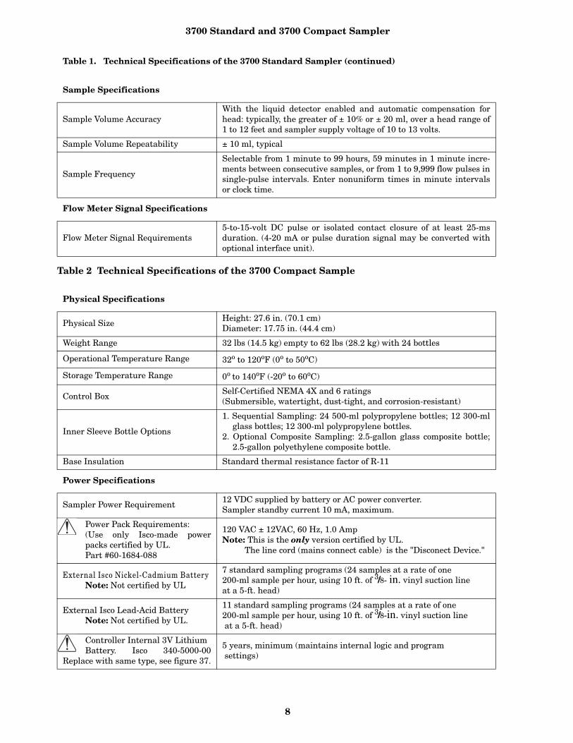
Table 2 Technical Specifications of the 3700 Compact Sample
Table 1. Technical Specifications of the 3700 Standard Sampler (continued)
Sample Specifications
Sample Volume AccuracyWith the liquid detector enabled and automatic compensation forhead: typically, the greater of ± 10% or ± 20 ml, over a head range of1 to 12 feet and sampler supply voltage of 10 to 13 volts.
Sample Volume Repeatability ± 10 ml, typical
Sample Frequency
Selectable from 1 minute to 99 hours, 59 minutes in 1 minute incre-ments between consecutive samples, or from 1 to 9,999 flow pulses insingle-pulse intervals. Enter nonuniform times in minute intervalsor clock time.
Flow Meter Signal Specifications
Flow Meter Signal Requirements5-to-15-volt DC pulse or isolated contact closure of at least 25-msduration. (4-20 mA or pulse duration signal may be converted withoptional interface unit).
Physical Specifications
Physical SizeHeight: 27.6 in. (70.1 cm)Diameter: 17.75 in. (44.4 cm)
Weight Range 32 lbs (14.5 kg) empty to 62 lbs (28.2 kg) with 24 bottles
Operational Temperature Range 32o to 120oF (0o to 50oC)
Storage Temperature Range 0o to 140oF (-20o to 60oC)
Control Box Self-Certified NEMA 4X and 6 ratings(Submersible, watertight, dust-tight, and corrosion-resistant)
Inner Sleeve Bottle Options
1. Sequential Sampling: 24 500-ml polypropylene bottles; 12 300-mlglass bottles; 12 300-ml polypropylene bottles.
2. Optional Composite Sampling: 2.5-gallon glass composite bottle;2.5-gallon polyethylene composite bottle.
Base Insulation Standard thermal resistance factor of R-11
Power Specifications
Sampler Power Requirement12 VDC supplied by battery or AC power converter.Sampler standby current 10 mA, maximum.
Power Pack Requirements:(Use only Isco-made powerpacks certified by UL. Part #60-1684-088
120 VAC ± 12VAC, 60 Hz, 1.0 AmpNote: This is the only version certified by UL.
The line cord (mains connect cable) is the "Disconect Device."
External Isco Nickel-Cadmium Battery Note: Not certified by UL
7 standard sampling programs (24 samples at a rate of one 200-ml sample per hour, using 10 ft. of 3/8- in. vinyl suction line at a 5-ft. head)
External Isco Lead-Acid Battery Note: Not certified by UL.
11 standard sampling programs (24 samples at a rate of one 200-ml sample per hour, using 10 ft. of 3/8-in. vinyl suction line at a 5-ft. head)
Controller Internal 3V LithiumBattery. Isco 340-5000-00
Replace with same type, see figure 37.
5 years, minimum (maintains internal logic and program settings)
3700 Standard and 3700 Compact Sampler
9
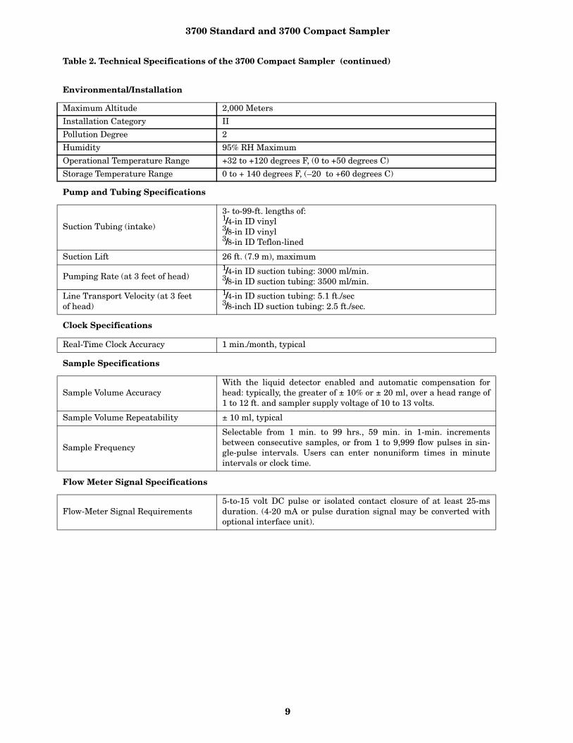
Table 2. Technical Specifications of the 3700 Compact Sampler (continued)
Environmental/Installation
Maximum Altitude 2,000 Meters
Installation Category II
Pollution Degree 2
Humidity 95% RH Maximum
Operational Temperature Range +32 to +120 degrees F, (0 to +50 degrees C)
Storage Temperature Range 0 to + 140 degrees F, (–20 to +60 degrees C)
Pump and Tubing Specifications
Suction Tubing (intake)
3- to-99-ft. lengths of: 1/4-in ID vinyl3/8-in ID vinyl3/8-in ID Teflon-lined
Suction Lift 26 ft. (7.9 m), maximum
Pumping Rate (at 3 feet of head)1/4-in ID suction tubing: 3000 ml/min.3/8-in ID suction tubing: 3500 ml/min.
Line Transport Velocity (at 3 feet of head)
1/4-in ID suction tubing: 5.1 ft./sec3/8-inch ID suction tubing: 2.5 ft./sec.
Clock Specifications
Real-Time Clock Accuracy 1 min./month, typical
Sample Specifications
Sample Volume AccuracyWith the liquid detector enabled and automatic compensation forhead: typically, the greater of ± 10% or ± 20 ml, over a head range of1 to 12 ft. and sampler supply voltage of 10 to 13 volts.
Sample Volume Repeatability ± 10 ml, typical
Sample Frequency
Selectable from 1 min. to 99 hrs., 59 min. in 1-min. incrementsbetween consecutive samples, or from 1 to 9,999 flow pulses in sin-gle-pulse intervals. Users can enter nonuniform times in minuteintervals or clock time.
Flow Meter Signal Specifications
Flow-Meter Signal Requirements5-to-15 volt DC pulse or isolated contact closure of at least 25-msduration. (4-20 mA or pulse duration signal may be converted withoptional interface unit).
3700 Standard and 3700 Compact Sampler
10
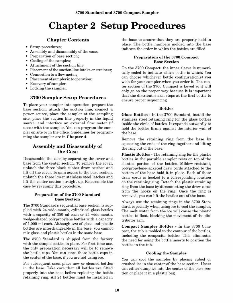
Chapter 2 Setup ProceduresChapter Contents
• Setup procedures; • Assembly and disassembly of the case;• Preparation of base section; • Cooling of the samples; • Attachment of the suction line;• Placement of the suction-line intake or strainers; • Connection to a flow meter; • Placement of sampler in to operation; • Recovery of sampler; • Locking the sampler.
3700 Sampler Setup ProceduresTo place your sampler into operation, prepare thebase section, attach the suction line, connect apower source, place the sampler at the samplingsite, place the suction line properly in the liquidsource, and interface an external flow meter (ifused) with the sampler. You can program the sam-pler on site or in the office. Guidelines for program-ming the sampler are in Chapter 4.
Assembly and Disassembly of the Case
Disassemble the case by separating the cover andbase from the center section. To remove the cover,unlatch the three black rubber draw catches andlift off the cover. To gain access to the base section,unlatch the three lower stainless steel latches andlift the center section straight up. Reassemble thecase by reversing this procedure.
Preparation of the 3700 Standard Base Section
The 3700 Standard’s sequential base section, is sup-plied with 24 wide-mouth, cylindrical glass bottleswith a capacity of 350 ml each or 24 wide-mouth,wedge-shaped polypropylene bottles with a capacityof 1,000 ml each. Although sets of glass and plasticbottles are interchangeable in the base, you cannotmix glass and plastic bottles in the same base.
The 3700 Standard is shipped from the factorywith the sample bottles in place. For first-time use,the only preparation necessary will be to removethe bottle caps. You can store these bottle caps inthe center of the base, if you are not using ice.
For subsequent uses, place new or cleaned bottlesin the base. Take care that all bottles are fittedproperly into the base before replacing the bottleretaining ring. All 24 bottles must be installed in
the base to assure that they are properly held inplace. The bottle numbers molded into the baseindicate the order in which the bottles are filled.
Preparation of the 3700 Compact Base Section
On the 3700 Compact, the inner sleeve is numeri-cally coded to indicate which bottle is which. Youcan choose whichever bottle configuration(s) youwish for your sampler when you order it. The cen-ter section of the 3700 Compact is keyed so it willonly go on the proper way because it is importantthat the distributor arm stops at the first bottle toensure proper sequencing.
Bottles
Glass Bottles - In the 3700 Standard, install thestainless steel retaining ring for the glass bottlesinside the circle of bottles. It expands outwardly tohold the bottles firmly against the interior wall ofthe base.
Remove the retaining ring from the base bysqueezing the ends of the ring together and liftingthe ring out of the base.
Plastic Bottles - The retaining ring for the plasticbottles in the portable sampler rests on top of theslanted portion of the bottles. Mildew-resistant,polypropylene-jacketed draw cords attached to thebottom of the base hold it in place. Each of thesedraw cords is hooked to a corresponding locationon the retaining ring. Detach the plastic retainingring from the base by disconnecting the draw cordsfrom the hooks on the ring. Once the ring isremoved, you can lift the bottles out of the base.
Always use the retaining rings in the 3700 Stan-dard, especially when using ice to cool the samples.The melt water from the ice will cause the plasticbottles to float, blocking the movement of the dis-tributor arm.
Compact Sampler Bottles - In the 3700 Com-pact, the tub is molded to the contour of the bottles,including the composite bottles. This eliminatesthe need for using the bottle inserts to position thebottles in the tub.
Cooling the Samples
You can cool the samples by placing cubed orcrushed ice in the center of the base section. Userscan either dump ice into the center of the base sec-tion or place it in a plastic bag.
3700 Standard and 3700 Compact Sampler
11
For the most uniform cooling, it is best to let themelt water from the ice run between the samplebottles, creating an ice bath. The quantity of iceused is dependent upon the required sample tem-perature and the ambient temperature of the sam-pling site. The capacity of the 3700 Standard baseis approximately 30 pounds of cubed ice whenglass bottles are used and 10 pounds when plasticbottles are used. The capacity for the 3700 Com-pact is 16 pounds. For maximum cooling, fill thebase (with bottles in place, as well as the 3700Standard’s retaining ring) with water and freezethe base and contents.
Insulation - Both the center section and the basesection have double-walled construction with poly-urethane foam insulation. The insulation on bothportable models has a standard thermal resistancefactor of R-11.
Attaching the Suction Line
The suction line is the piece of tubing that extendsfrom the sampler’s pump tubing intake, at the topof the liquid detector, to the liquid source. Thereare three standard suction lines available: plasti-cized vinyl tubing in 1/4-inch (0.64-cm) or 3/8-inch(0.94-cm) inside diameters (IDs), or FEP Teflonwith a polyethylene cover in 3/8-inch ID. The poly-ethylene cover over the 0.02-inch (0.051-cm) wallTeflon line prevents the Teflon liner from kinkingor collapsing in service and protects it from dam-age. The vinyl suction line contains a very lowPPM (parts per million) level of phenols. If thisaffects your samples, use the Teflon suction line.
You can cut both vinyl and Teflon lines to anylength from 3 to 99 feet in 1-foot increments. Cutthe suction line in whole-foot increments: lengthsof 4 feet, not 3.5 feet. The controller will acceptonly whole numbers as suction-line lengths.
To ensure the accuracy of the sampler, you mustenter a suction-line length equal that of the actualline measurement. When programming the sam-pler, you must enter the inside diameter, type, andlength of suction line used.
Cut the line to the shortest length feasible: this aidsthe downhill routing. Avoid loops of coiled suctionline, which may hold residual amounts of liquid thatwould cross-contaminate sample volumes. A shortersuction line will also extend battery life and pump-tube life because the sampler will require a shorterpumping cycle to deliver the sample volume.
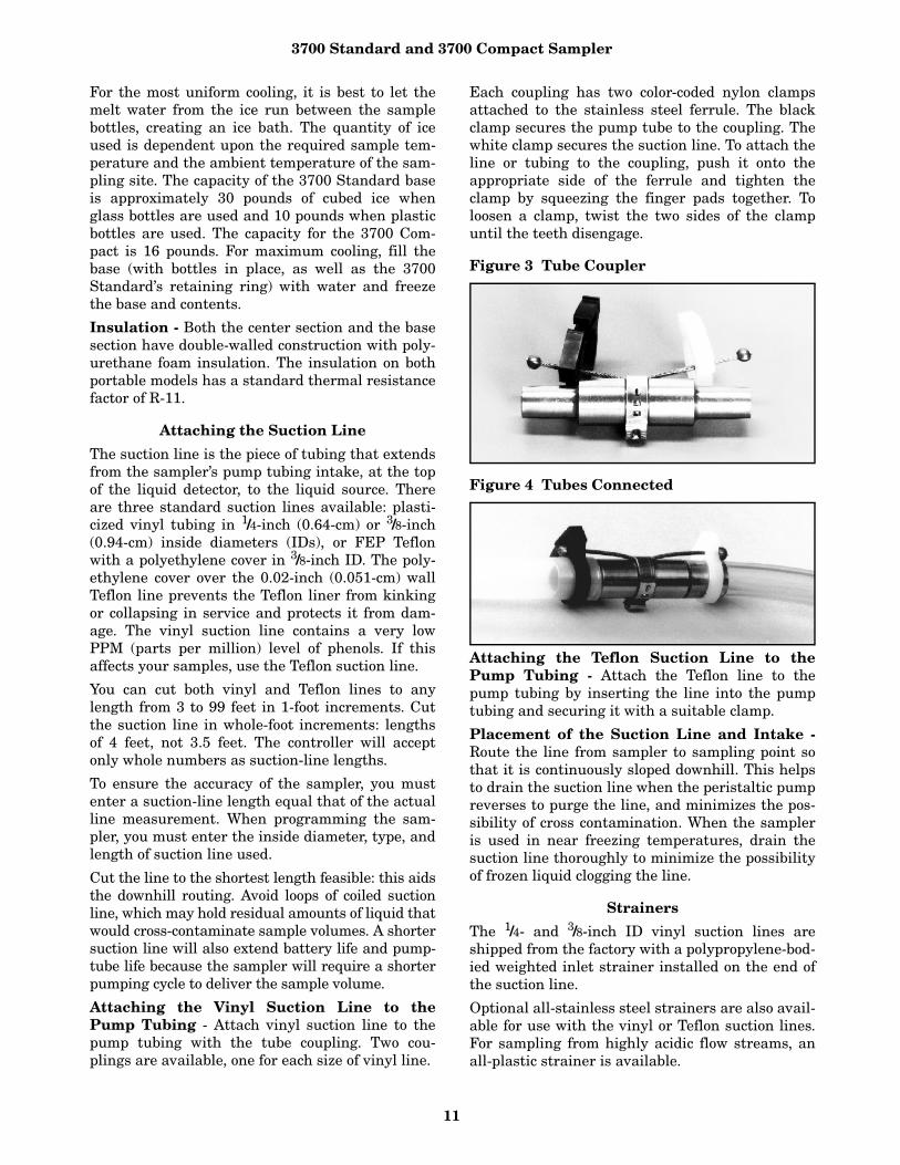
Attaching the Vinyl Suction Line to thePump Tubing - Attach vinyl suction line to thepump tubing with the tube coupling. Two cou-plings are available, one for each size of vinyl line.
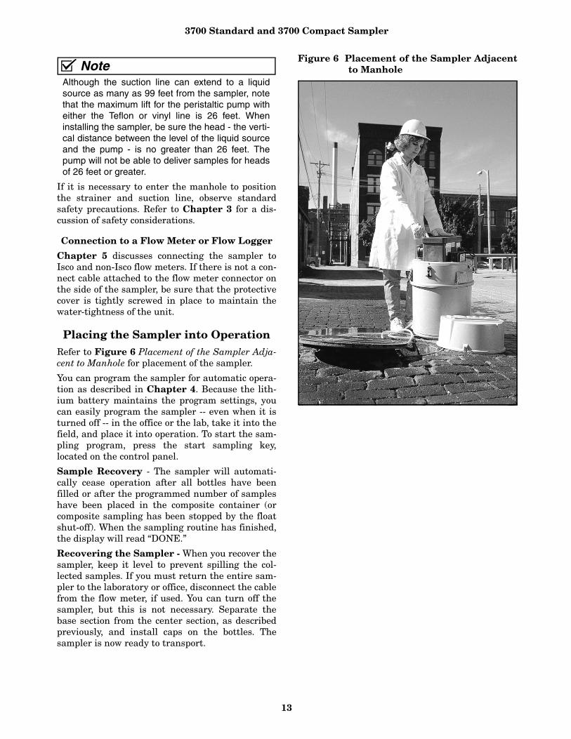
Each coupling has two color-coded nylon clampsattached to the stainless steel ferrule. The blackclamp secures the pump tube to the coupling. Thewhite clamp secures the suction line. To attach theline or tubing to the coupling, push it onto theappropriate side of the ferrule and tighten theclamp by squeezing the finger pads together. Toloosen a clamp, twist the two sides of the clampuntil the teeth disengage.
Figure 3 Tube Coupler
Figure 4 Tubes Connected
Attaching the Teflon Suction Line to thePump Tubing - Attach the Teflon line to thepump tubing by inserting the line into the pumptubing and securing it with a suitable clamp.
Placement of the Suction Line and Intake -Route the line from sampler to sampling point sothat it is continuously sloped downhill. This helpsto drain the suction line when the peristaltic pumpreverses to purge the line, and minimizes the pos-sibility of cross contamination. When the sampleris used in near freezing temperatures, drain thesuction line thoroughly to minimize the possibilityof frozen liquid clogging the line.
Strainers
The 1/4- and 3/8-inch ID vinyl suction lines areshipped from the factory with a polypropylene-bod-ied weighted inlet strainer installed on the end ofthe suction line.
Optional all-stainless steel strainers are also avail-able for use with the vinyl or Teflon suction lines.For sampling from highly acidic flow streams, anall-plastic strainer is available.

3700 Standard and 3700 Compact Sampler
12
You can purchase bulk suction line without strain-ers. Refer to the Accessories List in the back of thismanual. The strainer prevents solid particles largerthan a specific diameter from entering and cloggingthe suction line. Isco recommends its use for bottomsampling or sampling from streams containinglarge solids. The 1/4-inch strainers supplied for usewith the 1/4-inch ID suction line have 15/64-inch (0.56cm) diameter holes. The 3/8-inch strainers suppliedfor use with the vinyl or Teflon 3/8-inch ID suctionline have 23/64-inch (0.9 cm) diameter holes.
Weighted Strainer - The use of the weightedstrainer is optional. When heavy suspended solidsare involved and flow stream velocities are signifi-cant, some field investigation results indicate thatyou can obtain more representative samples with-out the strainer. If you don’t use the strainer, youcan attach a short piece of thin-walled aluminumtubing to the end of the suction line and anchor thetubing in the flow stream so that the inlet is ori-ented upstream. The thin wall will provide mini-mum disturbance of the flow stream, and aluminumions are usually not of concern in analysis. The pre-sample purge cycle should be sufficient to removeany debris that may collect over the strainer or tub-ing entrance between sampling events.
Intake Placement - The proper placement of thesampler intake assures the collection of represen-tative samples. Place the intake in the main flow,not in an eddy or at the edge of flow. The verticalposition of the intake in the flow is important. Anintake at the bottom may result in excess heavysolids and no floating materials, while placementat the top may result in the opposite.
The suction line tends to float in deep flowstreams, dislodging the line and strainer. Thechart below shows the maximum depths you cansubmerge the lines and strainers without risks offloatation. At depths exceeding the safe depths,anchor the line and strainer securely.
Attaching the Debris Deflector to theStrainer - A debris deflector prevents debris fromaccumulating on the hose clamp, which attachesthe strainer to the suction line. The 3/8-inchpolypropylene strainer is shipped with the suctionline attached and the debris deflector in place.
To replace the suction line on a strainer with adebris deflector:
1. Push the deflector back up the line to expose thehose clamp.
2. Loosen the clamp and pull the line from thestrainer’s ferrule.
3. Remove the deflector from the old line andthread it on the new line. Push the deflectorback on the new line; leave enough room to workwith the hose clamp.
4. Thread the hose clamp on the new line.5. Slip the line onto the ferrule and secure it with
the hose clamp.6. Push the debris deflector down the line and onto
the strainer.
Figure 5 Attaching the Debris Deflector
Connection to Power Source
The 3700 Series must use one of four 12 VDC powersources: an Isco AC Power Pack, an Isco Nickel-Cad-mium Battery Pack, an Isco sealed lead-acid bat-tery, or an external 12V direct current source (suchas an automotive or marine battery). For completeinformation on these power options and how tomaintain them, refer to the Power Products Guidethat was shipped with your sampler.
Placement of the Sampler
Refer to Figure 6 for sampler placement.
Place your sampler on a relatively flat surface.Placing it on a steep incline may cause the sampleto miss the bottle opening.
Strainer1/4" Vinyl
Line
3/8" Vinyl Line
3/8" Teflon Line
Stainless Steel ------- 22 feet 15 feet
Low-Flow StainlessSteel 14 feet 7 feet -------
Polypropylene 22 feet 11 feet -------
CPVC ------- 4 feet -------
DeflectorHose Clamp
3700 Standard and 3700 Compact Sampler
13
NoteAlthough the suction line can extend to a liquidsource as many as 99 feet from the sampler, notethat the maximum lift for the peristaltic pump witheither the Teflon or vinyl line is 26 feet. Wheninstalling the sampler, be sure the head - the verti-cal distance between the level of the liquid sourceand the pump - is no greater than 26 feet. Thepump will not be able to deliver samples for headsof 26 feet or greater.
If it is necessary to enter the manhole to positionthe strainer and suction line, observe standardsafety precautions. Refer to Chapter 3 for a dis-cussion of safety considerations.
Connection to a Flow Meter or Flow Logger
Chapter 5 discusses connecting the sampler toIsco and non-Isco flow meters. If there is not a con-nect cable attached to the flow meter connector onthe side of the sampler, be sure that the protectivecover is tightly screwed in place to maintain thewater-tightness of the unit.
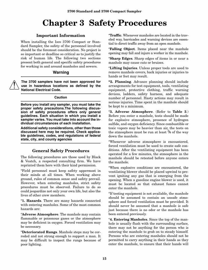
Placing the Sampler into OperationRefer to Figure 6 Placement of the Sampler Adja-cent to Manhole for placement of the sampler.
You can program the sampler for automatic opera-tion as described in Chapter 4. Because the lith-ium battery maintains the program settings, youcan easily program the sampler -- even when it isturned off -- in the office or the lab, take it into thefield, and place it into operation. To start the sam-pling program, press the start sampling key,located on the control panel.
Sample Recovery - The sampler will automati-cally cease operation after all bottles have beenfilled or after the programmed number of sampleshave been placed in the composite container (orcomposite sampling has been stopped by the floatshut-off). When the sampling routine has finished,the display will read “DONE.”
Recovering the Sampler - When you recover thesampler, keep it level to prevent spilling the col-lected samples. If you must return the entire sam-pler to the laboratory or office, disconnect the cablefrom the flow meter, if used. You can turn off thesampler, but this is not necessary. Separate thebase section from the center section, as describedpreviously, and install caps on the bottles. Thesampler is now ready to transport.
Figure 6 Placement of the Sampler Adjacentto Manhole

3700 Standard and 3700 Compact Sampler
14
Exchanging Sampler Tubs - If you do not needto return the entire 3700 Standard sampler to thelab, you can exchange the full base section for anempty one by separating the base from the centersection and installing an empty tub. After the fullbase has been removed, place caps on the bottles.Using the base section as a carrying case is conve-nient, prevents undue warming of cooled samples,and helps to prevent mix ups in bottle order. Anoptional cover, with carrying handles, for the basesection is available to aid in transportation. Attachthe cover to the base in the same manner as thecenter section. It is good practice to attach anadhesive label detailing the location, time, date,etc., of sampling to avoid confusion.
When exchanging bottle tubs, it is also good prac-tice to check the charge of the sampler’s battery. Ifthe sampler’s battery is questionable, exchange itwith a freshly charged battery.
With the 3700 Compact, there is no need to changebases. Slide the sleeve out to remove the bottles fortransporting off-site. Place caps on the bottles andyou may want to attach an adhesive label with rel-evant details on the sleeve as noted above.
Restarting - After you have installed the base sec-tion with empty bottles in the portable, or replacedthe full bottles in the sleeve with empty ones in thecompact, start the sampler again by pressing thestart sampling key. You may need to reprogram thestart time, if one has been entered.
Sampler Locking
To prevent tampering with the controls and sam-ple bottles, the sampler can be locked with thelocking cable accessory package. For standard-size3700 Samplers, use P/N 68-6700-134; use P/N 68-6700-111 for 3700 Compact Sampler. The sampleris secured with three stainless steel cables and apadlock. To secure the sampler, place the hook onthe end of the cable through the hole on the latch,as shown in Figure 7. Repeat this with the othertwo cables, and gather the ends of the cables withthe small loops at the center of the top cover. Then,feed the padlock through the loops and lock, asshown in Figure 8.
Figure 7 Locking the sampler
Figure 8 Locked sampler
3700 Standard and 3700 Compact Sampler
15
Chapter 3 Safety ProceduresImportant Information
When installing the Isco 3700 Compact or Stan-dard Sampler, the safety of the personnel involvedshould be the foremost consideration. No project isso important or deadline so critical as to justify therisk of human life. The following two sectionspresent both general and specific safety proceduresfor working in and around manholes and sewers.
Warning
The 3700 samplers have not been approved foruse in hazardous locations as defined by theNational Electrical Code.
Caution
Before you install any sampler, you must take theproper safety precautions.The following discus-sion of safety procedures offers only generalguidelines. Each situation in which you install asampler varies. You must take into account the in-dividual circumstances of each installation.Additional safety considerations, other than thosediscussed here may be required. Check applica-ble guidelines, codes, and regulations of federalstate, city, and county agencies
General Safety ProceduresThe following procedures are those used by Black& Veatch, a respected consulting firm. We havereprinted them here with their kind permission.
“Field personnel must keep safety uppermost intheir minds at all times. When working aboveground, rules of common sense and safety prevail.However, when entering manholes, strict safetyprocedures must be observed. Failure to do socould jeopardize not only your own life, but also thelives of other crew members.
“1. Hazards. There are many hazards connectedwith entering manholes. Some of the most commonhazards are:
“Adverse Atmosphere. The manhole may containflammable or poisonous gases or the atmospheremay be deficient in oxygen. Forced ventilation maybe necessary.
“Deteriorated Rungs. Manhole steps may be cor-roded and not strong enough to support a man. Itmay be difficult to inspect the rungs because ofpoor lighting.
“Traffic. Whenever manholes are located in the trav-eled way, barricades and warning devices are essen-tial to direct traffic away from an open manhole.
“Falling Object. Items placed near the manholeopening may fall and injure a worker in the manhole.
“Sharp Edges. Sharp edges of items in or near amanhole may cause cuts or bruises.
“Lifting Injuries. Unless proper tools are used toremove manhole covers, back injuries or injuries tohands or feet may result.
“2. Planning. Advance planning should includearrangements for test equipment, tools, ventilatingequipment, protective clothing, traffic warningdevices, ladders, safety harness, and adequatenumber of personnel. Hasty actions may result inserious injuries. Time spent in the manhole shouldbe kept to a minimum.
“3. Adverse Atmosphere. (Refer to Table 3.)Before you enter a manhole, tests should be madefor explosive atmosphere, presence of hydrogensulfide, and oxygen deficiency. Since combustible ortoxic vapors may be heavier than air, the tests onthe atmosphere must be run at least 3/4 of the waydown the manhole.
“Whenever adverse atmosphere is encountered,forced ventilation must be used to create safe con-ditions. After the ventilating equipment has beenoperated for a few minutes, the atmosphere in themanhole should be retested before anyone entersthe manhole.
“When explosive conditions are encountered, theventilating blower should be placed upwind to pre-vent igniting any gas that is emerging from theopening. When a gasoline engine blower is used, itmust be located so that exhaust fumes cannotenter the manhole.
“If testing equipment is not available, the manholeshould be assumed to contain an unsafe atmo-sphere and forced ventilation must be provided. Itshould never be assumed that a manhole is safejust because there is no odor or the manhole hasbeen entered previously.
“4. Entering Manholes. Since the top of the man-hole is usually flush with the surrounding surface,there may not be anything for the person who isentering the manhole to grab on to steady himself.Persons who are entering manholes should not bepermitted to carry anything in their hands as theyenter the manhole, to ensure that their hands will
3700 Standard and 3700 Compact Sampler
16
be free to hold on or grab if they slip. A good methodfor entering a manhole is to sit on the surface fac-ing the manhole steps or ladder, with the feet in thehole and the arms straddling the opening for sup-port. As the body slides forward and downward, thefeet can engage a rung, and the back can restagainst the opposite side of the opening. If there isany doubt about the soundness of the manholesteps, a portable ladder should be used.
“A person should never enter a manhole unless heis wearing personal safety equipment, including asafety harness and a hard hat. Two persons shouldbe stationed at the surface continuously while any-one is working inside a manhole, to lift him out ifhe is overcome or injured. One man cannot lift anunconscious man out of a manhole. The personsstationed at the surface should also function asguards to keep people and vehicles away from themanhole opening. To avoid a serious injury, a per-son should not be lifted out of a manhole by hisarm unless it is a dire emergency.
“When more than one person must enter a man-hole, the first person should reach the bottom andstep off the ladder before the next one starts down.When two men climb at the same time, the upperone can cause the lower one to fall by slipping orstepping on his fingers.
“5. Traffic Protection. In addition to traffic cones,markers, warning signs, and barricades, a vehicle ora heavy piece of equipment should be placedbetween the working area and oncoming traffic.Flashing warning signals should be used to alertdrivers and pedestrians. Orange safety vests shouldbe worn by personnel stationed at the surface whenthe manhole is located in a vehicular traffic area.
“6. Falling Object. All loose items should be keptaway from the manhole opening. This applies tohand tools as well as stones, gravel and other objects.
“7. Removing the Covers. Manhole coversshould be removed with a properly designed hook.Use of a pick ax, screwdriver, or small pry bar mayresult in injury. A suitable tool can be made from 3/4-inch round or hex stock. Two inches of one endshould be bent at a right angle and the other endshould be formed into a D-handle wide enough toaccommodate both hands. Even with this tool, caremust be exercised to prevent the cover from beingdropped on the toes. The 2-inch projection shouldbe inserted into one of the holes in the cover, thehandle grasped with both hands, and the coverlifted by straightening the legs which have beenslightly bent at the knees.
“8. Other Precautions. Other precautions whichshould be taken when entering a manhole are:
• Wear a hard hat.• Wear coveralls or removable outer garment
which can be readily removed when the work iscompleted.
• Wear boots or non-sparking safety shoes.• Wear rubberized or waterproof gloves.• Wear a safety harness with a stout rope
attached.• Do not smoke.• Avoid touching yourself above the collar until
you have cleaned your hands.
“9. Emergencies. Every member of the crewshould be instructed on procedures to be followed inan emergency. Each crew chief must have a list ofemergency phone numbers, including the nearesthospital and ambulance service, police precinct, firestation, and rescue or general emergency number.
“10. Field Equipment. The following equipmentwill be available for use:
Blowers Hard Hats
Breathing apparatus Harnesses
Coveralls Manhole irons
First aid kits Pick axes
Emergency flashers Rain slickers
Flashlights Ropes
Mirrors Safety vests
Gas detectors Traffic cones
Gas masks Waders
Gloves”
Lethal Atmospheres in SewersThe following is an article written by Dr. RichardD. Pomeroy, and published in the October 1980issue of Deeds & Data of the WPCF. Dr. Pomeroy isparticularly well known for his studies, over aperiod of nearly 50 years, in the field of the controlof hydrogen sulfide and other odors in sewers andtreatment plants. He has personally worked in agreat many functioning sewers. In the earlieryears he did so, he admits, with little knowledge ofthe grave hazards to which he exposed himself. Dr.Pomeroy writes:
"It is gratifying that the subject of hazards to peo-ple working in sewers is receiving much moreattention than in past years, and good safety proce-dures are prescribed in various publications onthis subject. It is essential that people know anduse correct procedures.
"It is less important to know just what the hazard-ous components of sewer atmospheres are, as safety

3700 Standard and 3700 Compact Sampler
17
precautions should in general be broadly applicable,but there should be a reasonable understanding ofthis subject. It is disturbing to see statements inprint that do not reflect true conditions.
"One of the most common errors is the assumptionthat people have died from a lack of oxygen. Thehuman body is able to function very well with sub-stantially reduced oxygen concentrations. No oneworries about going to Santa Fe, New Mexico, (ele-vation 2,100 meters), where the partial pressure ofoxygen is equal to 16.2% (a normal atmosphere isabout 21%) oxygen. When first going there, a per-son may experience a little “shortness of breath”following exercise. People in good health are notafraid to drive over the high passes in the RockyMountains. At Loveland Pass, oxygen pressure is13.2% of a normal atmosphere. At the top of Mt.Whitney, oxygen is equal to 12.2%. Many hikers gothere, and to higher peaks as well. After adequateacclimation, they may climb to the top of Mt. Ever-est, where oxygen is equal to only 6.7%.
"The lowest oxygen concentrations that I haveobserved in a sewer atmosphere was 13%. It was ina sealed chamber, near sea level, upstream from aninverted siphon on a metropolitan trunk. A manwould be foolish to enter the chamber. Without ven-tilation, he might die, but not from lack of oxygen.
"It seems unlikely that anyone has ever died in asewer from suffocation, that is, a lack of oxygen.Deaths have often been attributed to “asphyxia-tion.” This is a word which, according to the dictio-nary, is used to mean death from an atmospherethat does not support life. The word has sometimesbeen misinterpreted as meaning suffocation, whichis only one kind of asphyxiation.
"In nearly all cases of death in sewers, the realkiller is hydrogen sulfide. It is important that thisfact be recognized. Many cities diligently test forexplosive gases, which is very important, and theymay measure the oxygen concentration which usu-ally is unimportant, but they rarely measure H2S.Death has occurred where it is unlikely that therewas any measurable reduction in the oxygen con-centration. Wastewater containing 2 mg/l of dis-solved sulfide, and at a pH of 7.0, can produce, in achamber with high turbulence, a concentration of300 ppm H2S, in the air. This is considered to be alethal concentration. Many people have died fromH2S, not only in sewers and industries, but alsofrom swamps and from hot springs. In one resortarea, at least five persons died from H2S poisoningbefore the people were ready to admit that H2S isnot a therapeutic agent. Hardly a year passes inthe U.S. without a sewer fatality from H2S as wellas deaths elsewhere in the world.
"The presence of H2S in a sewer atmosphere is eas-ily determined. A bellows-and-ampoule type oftester is very satisfactory for the purpose, eventhough it is only crudely quantitative. When using atester of this type, do not bring the air to theampoule by way of a tube, as this may change theH2S concentration. Hang the ampoule in the air tobe tested, with a suction tube to the bulb or bellows.
"Lead acetate paper is very useful as a qualitativeindicator. It cannot be used to estimate the amountof sulfide, but it will quickly turn black in an atmo-sphere containing only a tenth of a lethal concen-tration.
"Electrodes or other similar electrical indicatingdevices for H2S in air have been marketed. Some ofthem are known to be unreliable, and we know ofnone that have proved dependable. Do not use oneunless you check it at frequent intervals againstair containing known H2S concentrations. A sup-posed safety device that is unreliable is worse thannone at all.
"Remember that the nose fails, too, when it comesto sensing dangerous concentrations of H2S.
"Various other toxic gases have been mentioned insome publications. It is unlikely that any person hasbeen asphyxiated in a sewer by any of those othergases, except possibly chlorine. The vapor of gaso-line and other hydrocarbons is sometimes present inamounts that could cause discomfort and illness,but under that condition, the explosion hazardwould be far more serious. The explosimeter tests,as well as the sense of smell, would warn of the dan-ger. Pipelines in chemical plants might contain anynumber of harmful vapors. They, too, are sensed bysmell and explosimeter tests if they get into thepublic sewer. Such occurrences are rare.
"The attempt to instill a sense of urgency aboutreal hazards is diluted if a man is told to giveattention to a long list of things that in fact areirrelevant.
"Be very careful to avoid high H2S concentrations,flammable atmospheres, and hazards of physicalinjuries. Remember that much H2S may be releasedby the stirring up of sludge in the bottom of a struc-ture. Obey your senses in respect to irritating gases,such as chlorine (unconsciousness comes suddenlyfrom breathing too much). Be cautious aboutstrange odors. Do not determine percent oxygen inthe air. There is a danger that the result will influ-ence a man's thinking about the seriousness of thereal hazards. Most important, use ample ventila-tion, and do not enter a potentially hazardous struc-ture except in a good safety harness with two menat the top who can lift you out."
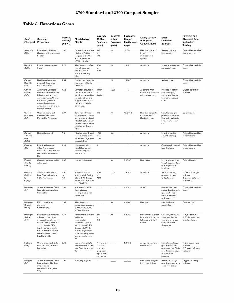
3700 Standard and 3700 Compact Sampler
18
Table 3 Hazardous Gases
Gas/Chemical
CommonProperties
SpecificGravity1
(Air =1)
PhysiologicalEffects2
Max Safe60-Min.Exposure(ppm)
Max Safe8-HourExposure(ppm)
Explosive Range3 Limits lower/upper
Likely Location of Highest Concentration
Most CommonSources
Simplest and Cheapest Safe Method of Testing
Ammonia(NH3)
Irritant and poisonous. Colorless with characteris-tic odor.
0.60 Causes throat and eye irritation at 0.05%, coughing at 0.17%. Short exposure at 0.5% to 1% fatal.
300to500
85 16 /25 Near top, concen-tratesin closed upper spaces.
Sewers, chemical feed rooms.
Detectable odor at low concentrations.
Benzene(C6H6)
Irritant, colorless anes-thetic.
2.77 Slight symptoms after several hours expo-sure at 0.16% to 0.32%. 2% rapidly fatal.
3,000to5,000
25 1.3 /7.1 At bottom. Industrial wastes, var-nishes, solvents.
Combustible gas indi-cator.
CarbonBisulfide(CS2)
Nearly odorless when pure, colorless, anes-thetic. Poisonous.
2.64 Irritation, vomiting, con-vulsions, psychic dis-turbances.
_____ 15 1.3/44.0 At bottom. An insecticide. Combustible gas indi-cator.
Carbon Dioxide(CO2)
Asphyxiant. Colorless, odorless. When breathed in large quantities may cause acid taste. Nonflam-mable. Not generally present in dangerous amounts unless an oxygen deficiency exists.
1.53 Cannot be endured at 10% for more than a few minutes, even if the subject is at rest and oxygen content is nor-mal. Acts on respira-tory nerves.
40,000to60,000
5,000 ____/ ____ At bottom; when heated may stratify at points above bottom.
Products of combus-tion, sewer gas, sludge. Also issues from carbonaceous strata.
Oxygen deficiency indicator.
Carbon Monoxide(CO)
Chemical asphyxiant.Colorless, tasteless.Flammable. Poisonous.
0.97 Combines with hemo-globin of blood. Uncon-scious in 30 minutes at 0.2% to 0.25%. Fatal in 4 hours at 0.1%. Head-ache in a few hours at 0.2%.
400 50 12.5/74.0 Near top, especiallyif present withilluminating gas.
Manufactured gas,products of combus-tion, motor exhausts. Fires of almost any kind.
CO ampoules.
Carbon Tetrachlo-ride(CCl4)
Heavy ethereal odor. 5.3 Intestinal upset, loss of consciousness, possi-ble renal damage, res-piratory failure.
1,000to1,500
100 ___ / ___ At bottom. Industrial wastes,solvent, cleaning.
Detectable odor at low concentrations.
Chlorine(Cl2)
Irritant. Yellow- green color. Choking odor detectable in very low con-centrations. Nonflamma-ble.
2.49 Irritates respiratory tract. Kills most ani-mals in a very short time at 0.1%.
4 1 ___ / ___ At bottom. Chlorine cylinder and feed-line leeks.
Detectable odor at low concentrations.
Formal-dehyde(CH2O)
Colorless, pungent, suffo-cating odor.
1.07 Irritating to the nose. _____ 10 7.0/73.0 Near bottom. Incomplete combus-tion of organics. Com-mon air pollutant, fungicide.
Detectable odor.
Gasoline(C5H12
toC9H20)
Volatile solvent. Color-less. Odor noticeable at 0.3%. Flammable.
3.0to4.0
Anesthetic effects when inhaled. Rapidly fatal at 2.4%. Danger-ous for short exposure at 1.1%to 2.2%.
4,000to7,000
1,000 1.3 /6.0 At bottom. Service stations, garages, storage tanks, houses.
1. Combustible gas indicator.2. Oxygen deficiency indicator.**
Hydrogen(H2)
Simple asphyxiant. Color-less, odorless, tasteless. Flammable.
0.07 Acts mechanically to deprive tissuesof oxygen. Does not support life.
_____ _____ 4.0/74.0 At top. Manufactured gas, sludge digestion tank gas, electrolysis of water. Rarely from rock strata.
Combustible gas indi-cator.
HydrogenCyanide(HCN)
Faint odor of bitter almonds. Colorless gas.
0.93 Slight symptoms appear upon exposure to 0.002%to 0.004%. 0.3% rapidly fatal.
_____ 10 6.0/40.0 Near top. Insecticide and rodenticide.
Detector tube.
HydrogenSulfide(H2S)
Irritant and poisonous vol-atile compound. Rotten egg odor in small concen-trations. Exposure for 2 to 15 minutes at 0.01% impairs sense of smell. Odor not evident at high concentrations. Color-less.Flammable.
1.19 Impairs sense of smell rapidly asconcentration increases. Death in a few minutes at 0.2%. Exposure 0.07% to 0.1% rapidly causes acute poisoning. Para-lyzes respiratory cen-ter.
200to300
20 4.3/45.0 Near bottom, but may be above bottom if air is heated and highly humid.
Coal gas, petroleum, sewer gas. Fumes from blasting under some conditions. Sludge gas.
1. H2S Ampoule.2. 5% by weight lead acetate solution.
Methane(CH4)
Simple asphyxiant. Color-less, odorless, tasteless, flammable.
0.55 Acts mechanically to deprive tissues of oxy-gen. Does not support life.
Probably no limit, pro-vided oxy-gen percen-tage is suffi-cient for life.
_____ 5.0/15.0 At top, increasing to certain depth.
Natural gas, sludge gas, manufactured gas, sewer gas. Strata of sedimentary origin. In swamps or marshes.
1. Combustible gas indicator.2. Oxygen deficiency indicator.
Nitrogen(N2)
Simple asphyxiant. Color-less, tasteless. Nonflam-mable Principle constituent of air (about 79%.)
0.97 Physiologically inert. - _____ ___/___ Near top but may be found near bottom.
Sewer gas, sludge gas. Also issues from some rock strata.
Oxygen deficiency indicator.

3700 Standard and 3700 Compact Sampler
19
Table Notes:
1. Specific Gravity is also known as Vapor Density2. Physiological effects given for concentrations over 0.3%.3. Explosive range given in percent by volume in air.4. Sludge gas consists predominately of methane and carbon dioxide with small amounts of hydrogen,
nitrogen, hydrogen sulfide, and oxygen; occasionally traces of carbon monoxide.
Nitrogen Oxide(NO
N2O
NO2)
Colorless.
Colorless, sweet odor.Reddish-brown, irritating odor. Deadly poison.
1.04
1.53
1.58
60 to 150 ppm causes irritation and coughing.
Asphyxiant.
100ppm dangerous, 200ppm fatal.
50 10 ___/___ Near bottom. Industrial wastes. Common air pollutant.
N02 detector tube.
Oxygen(in air)(O2)
Colorless, odorless, taste-less.Supports combustion.
1.11 Normal air contains 20.8% of 02. Man can tolerate down to 12%. Minutes.Safe 8 hr. exposure, 14 to 16%. Below 10%, danger-ous to life. Below 5 to 7% probably fatal.
_____ _____ ___/___ Variable at different levels.
Oxygen depletion from poor ventilation and absorption, or chemi-calconsumption of oxy-gen.
Oxygen deficiency indicator.
Ozone(O3)
Irritant and poisonous. Strong electrical odor. Strong oxidizer.Colorless. At 1 ppm, strong sulphur-like odor.
1.66 Max. naturally occur-ring level 0.4 ppm. 0.5 ppm causes irritation of eyes and nose. 1 to 10 ppm causes headache, nausea, can cause coma. Symptoms simi-lar to radiation dam-age.
0.08 0.04 ___ /___ Near bottom. Where ozone is used for disinfection.
Detectable odor at 0.015 ppm.
SludgeGas4
Mostly a simple asphyx-iant. May be practically odorless, colorless.
Variable Will not support life. No data. Would vary widely with composition.
5.3/19.3 Near top of structure. From digestion of sludge.
See components.
SulfurDioxide(SO2)
Colorless pungent odor.Suffocating, corrosive, poi-sonous, nonflammable.
2.26 Inflammation of the eyes. 400 to 500 ppm immediately fatal.
50 to100
10 ___/___ At bottom, can com-bine with water to form sulfurous acid.
Industrial waste, com-bustion, common air pollutant.
Detectable taste and odor at low concentra-tions.
Toluene(C7H8)
Colorless, benzene-like odor.
3.14 At 200-500 ppm, head-ache, nausea, bad taste, lassitude.
200 100 1.27/7.0 At bottom. Solvent. Combustible gas indi-cator.
Turpentine(C10H16)
Colorless, characteristic odor.
4.84 Eye irritation, head-ache, dizziness, nau-sea, irritation of the kidneys.
_____ 100 0.8/__ At bottom. Solvent used in paint. 1. Detectable odor at low concentrations.2. Combustible gas indicator.
Xylene(C8H10
Colorless, Flammable. 3.66 Narcotic in high con-centrations. Less toxic than benzene.
____ 100 1.1/7.0 At bottom. Solvent Combustible gas indi-cator.
Gas/Chemical
CommonProperties
SpecificGravity1
(Air =1)
PhysiologicalEffects2
Max Safe60-Min.Exposure(ppm)
Max Safe8-HourExposure(ppm)
Explosive Range3 Limits lower/upper
Likely Location of Highest Concentration
Most CommonSources
Simplest and Cheapest Safe Method of Testing
3700 Standard and 3700 Compact Sampler
20
Chapter 4 Programming GuidelinesIntroduction
This chapter, Programming Guidelines, discussesin detail the sampling features of the 3700 Porta-ble Samplers and the procedures for programmingyour sampler.
Isco has found that the most effective way to learnto program the 3700 Sampler is to read this chap-ter with a sampler in front of you. The time thatyou spend in the office or laboratory actually pro-gramming the sampler and observing its operationis usually time well spent.
If you are already familiar with the samplingcapabilities of the 3700 Sampler, you may preferto begin with the section entitled ProgrammingIntroduction on page 24. This section introducesthe specifics of programming the sampler.
• Description of Sampling Operations contains adescription of the sampling cycle, as well as theoperations.
• The Types of Samples section discusses sampletypes that can be taken in both basic andextended mode with the 3700 Sampler.
• The Programming Introduction section dis-cusses the sampler’s program structure andintroduces both basic and extended program-ming modes.
• The Operating States section discusses thesampler’s three operating states.
• Introduction to the Programming Proceduresdescribes the basic programming mode.
• The sections Using the Keypad to Respond toDisplays, Keypad Description, and Displaysdiscuss programming the sampler with thekeypad.
• Basic Programming provides examples for thebasic programming mode.
• The Configure Sequence section discusses howto tailor the sampler to your specific application.
• The Extended Programming Mode section dis-cusses the mode and presents programmingexamples.
• Foreign Languages and Metric Units of Mea-sure discusses adjusting the sampler for a for-eign language and or metric units.
• The Standby State section discusses youroptions when the sampler is in standby.
• The Run State section discusses what is occur-ring when your 3700 is operating in the runstate.
Description of Sampling OperationsThis information introduces the types of samplingperformed by the 3700 and the terminology thatdescribes those capabilities.
Sample Events and the Sampling Cycle
A sample event is the complete cycle involved intaking a sample. Although the cycle varies accord-ing to the program settings that define the sam-pling routine, the cycle described here follows thetypical sequence. The information presented hereis intended to provide you with a frame of refer-ence for the remainder of this chapter.
1. A sample event occurs when either the pro-grammed interval has expired or programmedflow volume has passed through the stream. The3700 takes a time-paced sample when an inter-nal clock reaches the time selected for the sam-ple. For flow-paced samples, the 3700 takes asample after receiving a specific of flow pulsesfrom the flow meter. Each flow pulse counts for aspecific flow volume as measured by the flowmeter.
2. When the time-interval expires or pulse-countreaches a user-programmed flow volume, thedistributor moves to the bottle that will receivethe sample.
3. For the pre-sample purge, the pump rotates inreverse. The pre-sample purge is an air purge ofthe suction line and inlet that clears the line ofany accumulated debris. It also purges residualliquid to avoid cross-contamination of samples.
4. The pump direction changes, moving forward tofill the suction line up to the liquid detector.
5. The sample-volume measuring portion of thesampling cycle begins after liquid fills the suc-tion line to the liquid detector. The pump rotatesforward until the programmed volume of liquidis delivered to the sample bottle. (In this man-ual, the amount of liquid delivered to the bottleis referred to as the “sample volume.”)
6. The pump direction changes, pumping in thereverse direction for the post-sample purge. Likethe pre-sample purge, the post-sample purge airpurges the suction line. After the post-samplepurge, the pump shuts off.
7. The sample interval resets and the cycleresumes at Step 1.
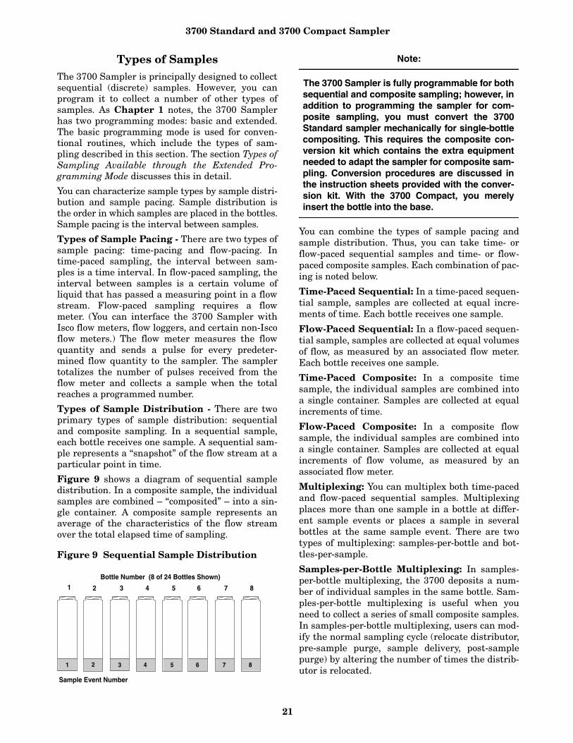
3700 Standard and 3700 Compact Sampler
21
Types of SamplesThe 3700 Sampler is principally designed to collectsequential (discrete) samples. However, you canprogram it to collect a number of other types ofsamples. As Chapter 1 notes, the 3700 Samplerhas two programming modes: basic and extended.The basic programming mode is used for conven-tional routines, which include the types of sam-pling described in this section. The section Types ofSampling Available through the Extended Pro-gramming Mode discusses this in detail.
You can characterize sample types by sample distri-bution and sample pacing. Sample distribution isthe order in which samples are placed in the bottles.Sample pacing is the interval between samples.
Types of Sample Pacing - There are two types ofsample pacing: time-pacing and flow-pacing. Intime-paced sampling, the interval between sam-ples is a time interval. In flow-paced sampling, theinterval between samples is a certain volume ofliquid that has passed a measuring point in a flowstream. Flow-paced sampling requires a flowmeter. (You can interface the 3700 Sampler withIsco flow meters, flow loggers, and certain non-Iscoflow meters.) The flow meter measures the flowquantity and sends a pulse for every predeter-mined flow quantity to the sampler. The samplertotalizes the number of pulses received from theflow meter and collects a sample when the totalreaches a programmed number.
Types of Sample Distribution - There are twoprimary types of sample distribution: sequentialand composite sampling. In a sequential sample,each bottle receives one sample. A sequential sam-ple represents a “snapshot” of the flow stream at aparticular point in time.
Figure 9 shows a diagram of sequential sampledistribution. In a composite sample, the individualsamples are combined – “composited” – into a sin-gle container. A composite sample represents anaverage of the characteristics of the flow streamover the total elapsed time of sampling.
Figure 9 Sequential Sample Distribution
Note:
The 3700 Sampler is fully programmable for bothsequential and composite sampling; however, inaddition to programming the sampler for com-posite sampling, you must convert the 3700Standard sampler mechanically for single-bottlecompositing. This requires the composite con-version kit which contains the extra equipmentneeded to adapt the sampler for composite sam-pling. Conversion procedures are discussed inthe instruction sheets provided with the conver-sion kit. With the 3700 Compact, you merelyinsert the bottle into the base.
You can combine the types of sample pacing andsample distribution. Thus, you can take time- orflow-paced sequential samples and time- or flow-paced composite samples. Each combination of pac-ing is noted below.
Time-Paced Sequential: In a time-paced sequen-tial sample, samples are collected at equal incre-ments of time. Each bottle receives one sample.
Flow-Paced Sequential: In a flow-paced sequen-tial sample, samples are collected at equal volumesof flow, as measured by an associated flow meter.Each bottle receives one sample.
Time-Paced Composite: In a composite timesample, the individual samples are combined intoa single container. Samples are collected at equalincrements of time.
Flow-Paced Composite: In a composite flowsample, the individual samples are combined intoa single container. Samples are collected at equalincrements of flow volume, as measured by anassociated flow meter.
Multiplexing: You can multiplex both time-pacedand flow-paced sequential samples. Multiplexingplaces more than one sample in a bottle at differ-ent sample events or places a sample in severalbottles at the same sample event. There are twotypes of multiplexing: samples-per-bottle and bot-tles-per-sample.
Samples-per-Bottle Multiplexing: In samples-per-bottle multiplexing, the 3700 deposits a num-ber of individual samples in the same bottle. Sam-ples-per-bottle multiplexing is useful when youneed to collect a series of small composite samples.In samples-per-bottle multiplexing, users can mod-ify the normal sampling cycle (relocate distributor,pre-sample purge, sample delivery, post-samplepurge) by altering the number of times the distrib-utor is relocated.
Bottle Number (8 of 24 Bottles Shown)
1 2 3 4 5 6 7 8
1 2 3 4 5 6 7 8
Sample Event Number

3700 Standard and 3700 Compact Sampler
22
Because a bottle will receive more than one samplefrom more than one sample event, the distributordoes not relocate to a new bottle at each sampleevent. At the first sample event, the distributorrelocates, if necessary, to the appropriate bottle. Thenormal sampling cycle is completed. At the nextsample event, the distributor does not relocate, anda second sample is deposited into the same bottle.
Figure 10 Samples-Per-Bottle Multiplexing
Figure 11 Bottles-Per-Sample Multiplexing
Compositing multiple samples continues up to theprogrammed number of samples. After the last sam-ple is deposited in the bottle, the sampler pausesuntil another sample event occurs, the distributorthen rotates to the new bottle position, and multiplesamples are deposited into the new bottle. Figure10 illustrates samples-per-bottle multiplexing.
Bottles-Per-Sample Multiplexing: In bottles-per-sample multiplexing, you fill a programmednumber of bottles at each sample event. (The pro-grammed number of bottles is a bottle set; as manyas 24 bottles can be used.) Bottles-per-sample mul-tiplexing is useful when you need a sample thatexceeds the capacity of your bottles. It is also use-ful when you need sets of identical samples; forexample, when using more than one preservative.
When you use bottles-per-sample multiplexing,you modify the normal sampling cycle (relocatedistributor, pre-sample purge, sample delivery,
post-sample purge) by delaying the complete post-sample purge until sample volumes have beendelivered to each bottle of the set. Instead, thepump reverses until the pump tubing is purgedjust beyond the liquid detector. When the purgedliquid passes the detector, the distributor moves tothe next bottle, and the pump begins pumping for-ward to deliver the next sample. This repeats untileach bottle of the set is filled. A full post-samplepurge is completed at the end of the sample event.The sampler then pauses until the next sampleevent occurs, at which time the cycle repeats forthe following bottle set. Figure 11 illustrates bot-tles-per-sample multiplexing.
Types of Sampling Available Through the Extended Programming Mode
The extended programming mode expands thevariations of sample pacing and distribution. Theextended features listed below are used in morecomplex sampling routines. Note, however, thatthe sampling capabilities described in the sectionTypes of Sample are available in both the basicand the extended programming modes. Note also,that STORM programming is available only in theextended programming mode.
Nonuniform Time Intervals: In the extendedprogramming mode, the 3700 Sampler can pacesamples at nonuniform time intervals. With non-uniform time intervals, the 3700 takes samples atirregular intervals, rather than at equal intervals.
Nonuniform time intervals are typically used inrun-off studies, often in conjunction with a Model1640 Liquid Level Actuator. Nonuniform timeintervals let you collect a number of samples atshort intervals after a rainfall or other eventoccurs and collect remaining samples at wideningintervals. For example, when you use the samplerwith the actuator in a run-off study, the actuatorturns on the sampler when the liquid level of theflow stream rises to contact the actuator’s probe.With nonuniform time intervals, the sampler cancollect samples frequently when the flow rate ishighest and less frequently as the flow ratedecreases.
You can also use nonuniform times to simulateflow-paced sampling. When the flow rate variespredictably, using nonuniform time intervalsallows you to take samples at equal flow volumes.As the flow-rate increases, you can take samples atequal flow volumes by decreasing the time inter-val. As the flow-rate decreases, you can increasethe time interval.
3
4
5
6
7
8
1
2
Bottle Number (8 of 24 Bottles Shown)1 2 3 4 5 6 7 8
Sample Event Number
1 1 2 2 3 3 4 4
Bottle Number (8 of 24 Bottles Shown)1 2 3 4 5 6 7 8
Sample Event Number
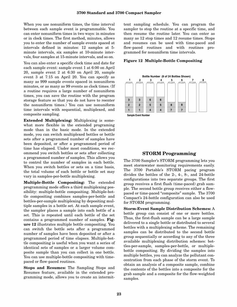
3700 Standard and 3700 Compact Sampler
23
When you use nonuniform times, the time intervalbetween each sample event is programmable. Youcan enter nonuniform times in two ways: in minutesor in clock times. The first method, minutes, allowsyou to enter the number of sample events spaced atintervals defined in minutes: 12 samples at 5-minute intervals, six samples at 10-minute inter-vals, four samples at 15-minute intervals, and so on.
You can also enter a specific clock time and date foreach sample event: sample event 1 at 6:00 on April20, sample event 2 at 6:30 on April 20, sampleevent 3 at 7:15 on April 20. You can specify asmany as 999 sample events spaced in nonuniformminutes, or as many as 99 events as clock times. (Ifa routine requires a large number of nonuniformtimes, you can save the routine with the programstorage feature so that you do not have to reenterthe nonuniform times.) You can use nonuniformtime intervals with sequential, multiplexed, andcomposite sampling.
Extended Multiplexing: Multiplexing is some-what more flexible in the extended programingmode than in the basic mode. In the extendedmode, you can switch multiplexed bottles or bottlesets after a programmed number of samples havebeen deposited, or after a programmed period oftime has elapsed. Under most conditions, we rec-ommend you switch bottles or sets after collectinga programmed number of samples. This allows youto control the number of samples in each bottle.When you switch bottles or sets on a time basis,the total volume of each bottle or bottle set mayvary in samples-per-bottle multiplexing.
Multiple-Bottle Compositing: The extendedprogramming mode offers a third multiplexing pos-sibility: multiple-bottle compositing. Multiple-bot-tle compositing combines samples-per-bottle andbottles-per-sample multiplexing by depositing mul-tiple samples in a bottle set. At each sample event,the sampler places a sample into each bottle of aset. This is repeated until each bottle of the setcontains a programmed number of samples. Fig-ure 12 illustrates multiple bottle compositing. Youcan switch the bottle sets after a programmednumber of samples have been deposited or after aprogrammed period of time elapses. Multiple-bot-tle compositing is useful when you want a series ofidentical sets of samples or a larger volume com-posite sample than you can collect in one bottle.You can use multiple-bottle compositing with time-paced or flow-paced routines.
Stops and Resumes: The Sampling Stops andResumes feature, available in the extended pro-gramming mode, allows you to create an intermit-
tent sampling schedule. You can program thesampler to stop the routine at a specific time, andthen resume the routine later. You can enter asmany as 12 stop times and 12 resume times. Stopsand resumes can be used with time-paced andflow-paced routines and with routines pro-grammed for nonuniform time intervals.
Figure 12 Multiple-Bottle Compositing
STORM Programming The 3700 Sampler’s STORM programming lets youmeet stormwater monitoring requirements easily.The 3700 Portable’s STORM pacing programdivides the bottles of the 2-, 4-, 8-, and 24-bottleconfigurations into two separate groups. The firstgroup receives a first flush (time-paced) grab sam-ple. The second bottle group receives either a flow-paced or time-paced “composite” sample. The 3700Compact’s 24-bottle configuration can also be usedfor STORM programming.
Storm-Event Sample Distribution Schemes: Abottle group can consist of one or more bottles.Thus, the first-flush sample can be a large sampledelivered to a single bottle or distributed to severalbottles with a multiplexing scheme. The remainingsamples can be distributed to the second bottlegroup sequentially or according to any of the threeavailable multiplexing distribution schemes: bot-tles-per-sample, samples-per-bottle, or multiple-bottle compositing. By dividing the samples intomultiple bottles, you can analyze the pollutant con-centration from each phase of the storm event. Toobtain an analysis of a composite sample, combinethe contents of the bottles into a composite for thegrab sample and a composite for the flow-weightedsamples.
1
2
3
1
2
3
4
5
6
4
5
6
7
8
7
8
Bottle Number (8 of 24 Bottles Shown)1 2 3 4 5 6 7 8
Sample Event Number

3700 Standard and 3700 Compact Sampler
24
Figure 13 shows a storm-distribution scheme thatcombines time-paced bottles-per-sample multiplex-ing with flow-paced samples-per-bottle multiplex-ing. The program has allocated bottles 1, 2, and 3for the timed grab samples, and bottles 4 through 24for flow-weighted samples. At each time-paced sam-ple event, the sampler places a single sample in thefirst bottle group: bottles 1, 2, and 3. Each bottle ofthe second group receives two samples per bottle.
Figure 13 Storm-Distribution Scheme
Programming IntroductionThe sampler’s programming process is self-prompt-ing. Prompts displayed on the LCD step youthrough the programming sequence in a logicalorder, indicating the needed value or option. Forexample, the sampler will prompt you to enter set-tings for the interval between samples (select eithertime-paced or flow-paced intervals); sample volumein ml; and other operating controls. These settingscan be changed at any time. The sampler acceptsonly appropriate values for the program settingsand rejects any unacceptable values. If you turn offthe unit or the power is disconnected, the lithiumbattery retains settings in the sampler’s memory.
Operating States
There are three operating states: the standby statewhere the sampler is waiting for your instructions,the run state where the sampler is running a sam-pling routine, and the interactive state, which isused to program the sampler. Each state serves adifferent purpose and is discussed separately.
Standby State– In the standby state, the sampleris waiting for your instructions. From standby, youcan start a sampling routine, placing the samplerin the run state. You can also access the interactivestate, which is discussed in an upcoming section.
Run State– In the run state, the sampler is exe-cuting the sampling routine and operating underprogram control. While the sampling routine isexecuted, the LCD displays a number of messagescommunicating the sampler’s progress throughthe routine.
It reports the current bottle or bottle set, currenttime or flow-pulse count, and remaining time orpulse count to the next sample. These messagesvary according to the sampling routine.
As the routine progresses, the sampler creates alog of sampling results that records pertinentinformation about each sample event. The resultsinclude the time and date of each sample, the num-ber of pump counts occurring until liquid isdetected for each sample event, and any problemsencountered.You can retrieve results with the Dis-play Status procedure, discussed in an upcomingsection in this chapter.
You can retrieve the results in the middle of a rou-tine or when the routine is done. The resultsremain in the sampler’s memory until you start thesampler again. See the section Run State for moreinformation.
Interactive State– The interactive state lets youprogram the sampler. The interactive state con-tains two branches: the program sequence and theconfigure sequence. Figure 14 diagrams thestructure of the interactive state. The programsequence defines the sampling routine; it allowsyou to enter the interval between samples, thenumber of samples in each bottle, the sample size,and the start time. The configure sequence pro-vides a number of setup options. Some configureoptions provide equipment specifications: bottlesizes, suction-line diameters and lengths, and soon. For example, the 3700 Standard can use differ-ent-sized sequential bottles: 350 ml and 1000 ml.You must enter the correct bottle size so that thesampler can calculate the range of sample vol-umes for a given number of samples and preventoverfilling. Other options allow you to set the sam-pler’s real-time clock, calibrate the sampler, orenable the password program protection.
Programming Modes
The configure sequence also allows you to selecteither of the programming modes: basic orextended.
Basic Programming– Use the basic program-ming mode for conventional sampling routines. Inthe basic programming mode, you can take sequen-tial or composite samples at uniform time intervalsor at flow-pulse intervals. You can multiplex sam-ples, if desired; both bottles-per-sample and sam-ples-per-bottle multiplexing are available. You cancontrol the start time of the routine by entering aspecific time and date or with the adjustable start-time delay.
Bottle Number (12 of 24 Bottles Shown)
1 2 3 4 5 6 7 8
Sample Event Number
10 11 129
11 1 222 3 5
4 6
7 9
8 10
11 13
12 14
Time-paced Segment Flow-paced Segment
Time Bottle Group Flow Bottle Group
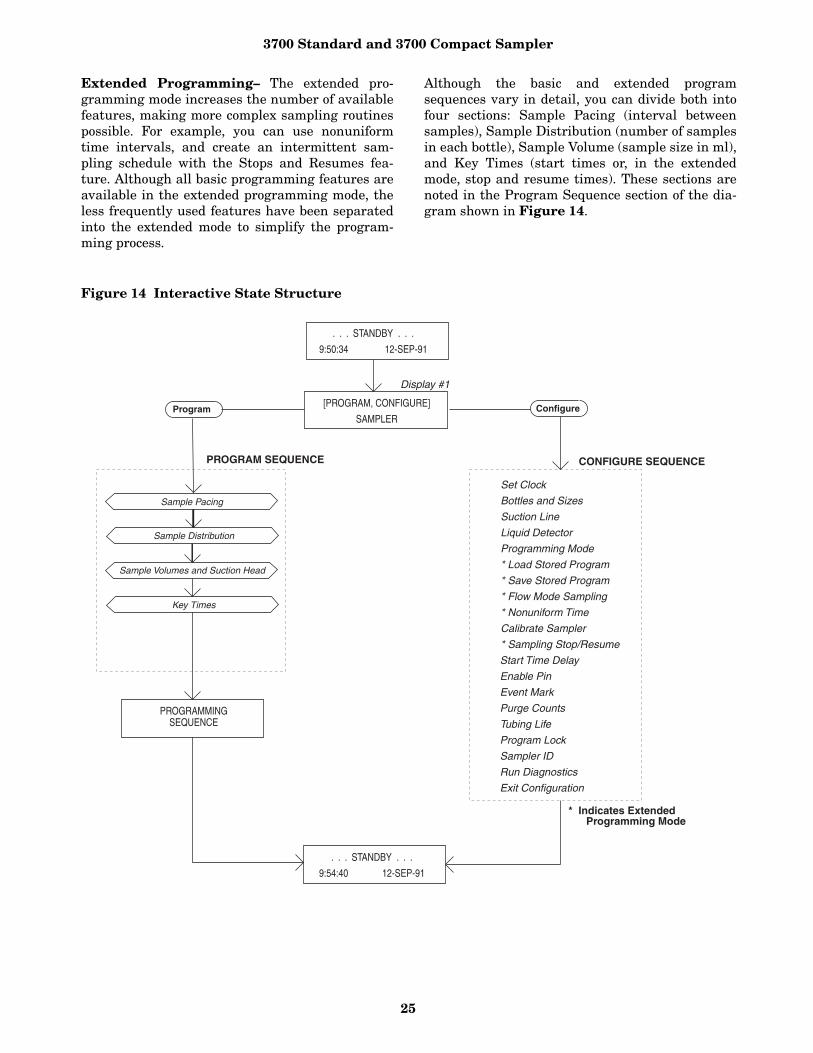
3700 Standard and 3700 Compact Sampler
25
Extended Programming– The extended pro-gramming mode increases the number of availablefeatures, making more complex sampling routinespossible. For example, you can use nonuniformtime intervals, and create an intermittent sam-pling schedule with the Stops and Resumes fea-ture. Although all basic programming features areavailable in the extended programming mode, theless frequently used features have been separatedinto the extended mode to simplify the program-ming process.
Although the basic and extended programsequences vary in detail, you can divide both intofour sections: Sample Pacing (interval betweensamples), Sample Distribution (number of samplesin each bottle), Sample Volume (sample size in ml),and Key Times (start times or, in the extendedmode, stop and resume times). These sections arenoted in the Program Sequence section of the dia-gram shown in Figure 14.
Figure 14 Interactive State Structure
[PROGRAM, CONFIGURE]
SAMPLERConfigure
. . . STANDBY . . .
9:54:40 12-SEP-91
. . . STANDBY . . .
9:50:34 12-SEP-91
Program
PROGRAM SEQUENCE CONFIGURE SEQUENCE
Set Clock
Bottles and Sizes
Suction Line
Liquid Detector
Programming Mode
* Load Stored Program
* Save Stored Program
* Flow Mode Sampling
* Nonuniform Time
Calibrate Sampler
* Sampling Stop/Resume
Start Time Delay
Enable Pin
Event Mark
Purge Counts
Tubing Life
Program Lock
Sampler ID
Run Diagnostics
Exit Configuration
Sample Pacing
Sample Distribution
Sample Volumes and Suction Head
Key Times
Display #1
PROGRAMMING SEQUENCE
* Indicates Extended Programming Mode
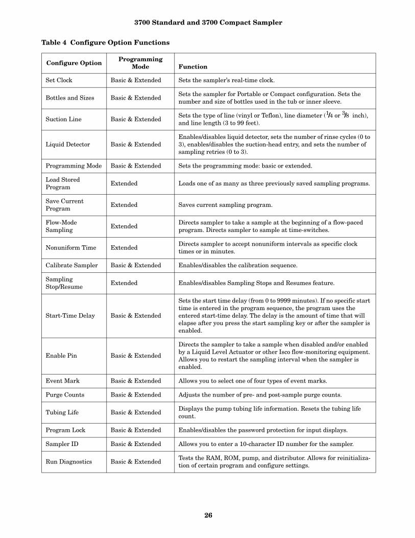
3700 Standard and 3700 Compact Sampler
26
Table 4 Configure Option Functions
Configure Option ProgrammingMode Function
Set Clock Basic & Extended Sets the sampler’s real-time clock.
Bottles and Sizes Basic & ExtendedSets the sampler for Portable or Compact configuration. Sets the number and size of bottles used in the tub or inner sleeve.
Suction Line Basic & ExtendedSets the type of line (vinyl or Teflon), line diameter (1/4 or 3/8 inch), and line length (3 to 99 feet).
Liquid Detector Basic & ExtendedEnables/disables liquid detector, sets the number of rinse cycles (0 to 3), enables/disables the suction-head entry, and sets the number of sampling retries (0 to 3).
Programming Mode Basic & Extended Sets the programming mode: basic or extended.
Load Stored Program
Extended Loads one of as many as three previously saved sampling programs.
Save Current Program
Extended Saves current sampling program.
Flow-Mode Sampling
ExtendedDirects sampler to take a sample at the beginning of a flow-paced program. Directs sampler to sample at time-switches.
Nonuniform Time ExtendedDirects sampler to accept nonuniform intervals as specific clock times or in minutes.
Calibrate Sampler Basic & Extended Enables/disables the calibration sequence.
SamplingStop/Resume
Extended Enables/disables Sampling Stops and Resumes feature.
Start-Time Delay Basic & Extended
Sets the start time delay (from 0 to 9999 minutes). If no specific start time is entered in the program sequence, the program uses the entered start-time delay. The delay is the amount of time that will elapse after you press the start sampling key or after the sampler is enabled.
Enable Pin Basic & Extended
Directs the sampler to take a sample when disabled and/or enabled by a Liquid Level Actuator or other Isco flow-monitoring equipment. Allows you to restart the sampling interval when the sampler is enabled.
Event Mark Basic & Extended Allows you to select one of four types of event marks.
Purge Counts Basic & Extended Adjusts the number of pre- and post-sample purge counts.
Tubing Life Basic & ExtendedDisplays the pump tubing life information. Resets the tubing life count.
Program Lock Basic & Extended Enables/disables the password protection for input displays.
Sampler ID Basic & Extended Allows you to enter a 10-character ID number for the sampler.
Run Diagnostics Basic & Extended Tests the RAM, ROM, pump, and distributor. Allows for reinitializa-tion of certain program and configure settings.

3700 Standard and 3700 Compact Sampler
27
Configure Sequence
The program sequence and the configure sequenceare interdependent. The selections you make in theconfigure sequence determine what settings will beavailable to you in the program sequence. When youselect the extended programming mode, the programsequence is modified to accommodate the extendedfeatures by adding one or more input displays.
The extended programming mode not only extendsthe number of features available in the programsequence, it extends the number of configureoptions. When you select extended programming,for example, you can enable the Sampling Stop andResumes and/or Nonuniform Times features so youcan use them in the extended program sequence.
When you select the basic programming mode,these configure options are not available to you. Asin the programming sequence, less frequently usedoptions have been separated to simplify the config-uration process.
Most configure options are available in both pro-gramming modes. Table 4 summarizes the config-ure sequence options; each option is marked asavailable in both modes or available only in theextended mode. A detailed discussion of each con-figuration option is found in the sections beginningwith Set Clock through Exit Configuration.
It is usually not necessary to change the configureoption settings unless the sampling applicationchanges significantly. The sampler is always pro-grammed and configured: the sampler’s internalbattery maintains program and configure settings.In fact, the sampler is shipped with factory pro-gram and configure settings. It is configured forthe basic program mode and for the bottle configu-ration and suction line ordered with the sampler.
Introduction to the Programming Procedure
The procedure used to program the sampler fol-lows the steps listed below. Note: Because the con-figuration settings determine portions of theprogram sequence and affect the accuracy of thesample, check the configuration settings beforeprogramming.
1. Determine the equipment you will be using withthe sampler. You will need to know the capacityof the bottles and the inside diameter, type(vinyl or Teflon), and length of the suction line.You will need this information to verify andrevise the configuration settings in step 2. If you will be using the sampler for compositesampling, you may need to convert the sampler.
The section Conversion for Composite Samplingin Chapter 5 provides information on convertingthe 3700 Standard for composite sampling.Example 6 demonstrates the configurationchanges you must make.
2. Check the configuration settings. From standby,access the interactive state. Select the configuresequence. Check the configuration settings,revising any settings as needed; select basic orextended programming mode. Return to thestandby state. Example 1 shows you how to check and revisethe configuration settings in the configuresequence. (We recommend you review theupcoming sections Keypad Description and Dis-plays before you work through the programmingexamples. These sections discuss the functionsof the individual keys and how to use the keyswhen programming the sampler.)
3. Program the sampler. Again, from standby,access the interactive state. Select the programsequence. Enter the program settings for yourroutine. The sampler will prompt you throughthe programming process. When the process iscompleted, the sampler will automaticallyreturn to standby. For a more detailed discussion of the program-ming procedure, see the section Basic Program-ming Procedure. The examples given demonstrateseveral types of sampling programs in the basicmode. Examples of extended mode sampling pro-grams are also shown.
4. If desired, connect the sampler to a flow meter orother interfacing equipment. Start the sampler.
5. As the routine is executed, the displays willreport the sampler’s progress. The programmingexamples in this manual conclude with the run-state displays you should see for each samplingroutine. When the routine is done, the samplerwill return to standby.
6. Retrieve the filled sample bottles. If you wish,use the Display Status procedure discussed indetail later in this chapter to examine the sam-pler’s log of sampling results.
7. If you need to reprogram the sampler, follow thisprocedure from the beginning. If the sampler’scurrent program is correct, restart the samplingroutine.
Using the Keypad to Respond to Displays
Configuring and programming the sampler is assimple as responding to displays on the LCD withthe keypad. The sampler will prompt you throughmany of the entries by presenting a question or a

3700 Standard and 3700 Compact Sampler
28
choice on the display. You must respond with thekeypad. The LCD and the keypad are located onthe 3700 Sampler control panel.
The following section, Keypad Description, summa-rizes each key’s function. The section Displays dis-cusses LCD displays and ways you can use thekeypad to interact with the sampler.
Keypad Description
Keys are grouped together on the control panel toassist you in identifying related functions. Controlkeys manually control the sampler; numeric keysare used to enter program values; programmingkeys are used to monitor the sampler’s status anddirect programming activities. Key names are rep-resented by small capital letters in this manual.
The individual key switches that make up the key-pad provide tactile and audible feedback to assureyou that the key switch has been successfully actu-ated. When you press a key switch, you can feel thedeflection of the spring member in the switch; anaudio indicator inside the sampler will beep once.The sampler has a 10-keystroke buffer which, insome cases, allows you to “type ahead” of the display.
Control Keys - Control keys let you turn the sam-pler on or off, start or resume the currently enteredprogram, and control the sampler manually. Con-trol key functions are:
• ON/OFF - Pressing the on/off key when thesampler is off will turn the sampler on, reacti-vate the display, and place the sampler in thestandby state. Pressing the on/off key (whenthe sampler is on) will halt all sampling activ-ity and clear the display.
• PUMP FORWARD - While in the standby state,pressing the pump forward key will cause thepump to run continuously in the forward direc-tion. The pump will run until you press thestop key.
• PUMP REVERSE - While in the standby state,pressing the pump reverse key will run thepump continuously in reverse. The pump willrun until you press the stop key.
• STOP - The stop key will stop the pump anytime it is running. When you press the stop keyin the run state, the sampling routine will halt,the sampler will transfer to the standby state,and the “PROGRAM HALTED” message willbe displayed. Pressing the stop key while inthe interactive state will access the display’sreference number.
• START SAMPLING - When in the standbystate, pressing the start sampling key willbegin the sampling program. When entering asampler ID, the key will type a space.
• RESUME SAMPLING - When “PROGRAMHALTED” is displayed, pressing the resumesampling key will cause the sampler to con-tinue with the current sample program at thepoint were it was halted. When entering asampler ID, the key will type a period.
• MANUAL SAMPLE - Pressing the manual sam-ple key will allow you to take a manual sample.The manual sample key is valid in the standbystate, the run state, and when calibrating thesampler. When entering a sampler ID, the keywill type a dash (-).
• NEXT BOTTLE - Pressing the next bottle keywill cause the distributor to move to the nextbottle. If the distributor is positioned over thelast bottle, it will move to bottle position 1.
Program Keys - The four program keys are usedto enter program settings. Each key’s function islisted below.
• DISPLAY STATUS - While the sampler is in thestandby or run state, pressing the display sta-tus key allows you to view the program set-tings or the sampling results.
• EXIT PROGRAM - Pressing the exit programkey while in the program sequence will returnthe sampler to standby. If you press the exitprogram key while in the run state, it will haltthe program; the message “PROGRAMHALTED” will be displayed.
• CLEAR ENTRY - When entering a number, usethe clear entry key to return to the original entry.
• ENTER/PROGRAM - Press the enter/programkey, while in the standby state to cause the sam-pler to enter the interactive state. While at aninput display, press the enter/program key toaccept an entered value or a blinking option anddirect the sampler to proceed to the next step.
Numeric Keys - The numeric keys consist of 10digit keys, a left arrow key, and a right arrow key.You use the digit keys to enter quantities and thearrow keys to move through the configure optionlist or program options.
• Left Arrow - Press the left arrow key to selectone of two or more program options displayedwhen the sampler is in the interactive state.When more than one numeric entry is dis-played – for example, the hours and minutes ofa time setting – you can use the left arrow tostep back to a previously entered value. Whenentering a number, use the left arrow to erasethe most recently entered digit. It is also usedto step through display status information andconfigure option list.
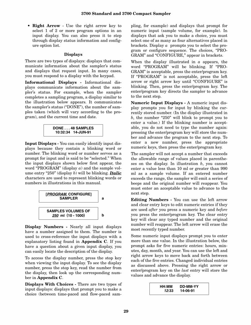
3700 Standard and 3700 Compact Sampler
29
• Right Arrow - Use the right arrow key toselect 1 of 2 or more program options in aninput display. You can also press it to stepthrough display status information and config-ure option list.
Displays
There are two types of displays: displays that com-municate information about the sampler’s statusand displays that request input. In many cases,you must respond to a display with the keypad.
Informational Displays - Informational dis-plays communicate information about the sam-pler’s status. For example, when the samplercompletes a sampling program, a display similar tothe illustration below appears. It communicatesthe sampler’s status (“DONE”), the number of sam-ples taken (which will vary according to the pro-gram), and the current time and date.
Input Displays - You can easily identify input dis-plays because they contain a blinking word ornumber. The blinking word or number serves as aprompt for input and is said to be “selected.” Whenthe input displays shown below first appear, theword “PROGRAM” (display a) and the sample vol-ume entry “250” (display b) will be blinking. Italiccharacters are used to represent blinking words ornumbers in illustrations in this manual.
Display Numbers - Nearly all input displayshave a number assigned to them. The number isused to cross-reference the input displays with aexplanatory listing found in Appendix C. If youhave a question about a given input display, youcan easily locate the description of the display.
To access the display number, press the stop keywhen viewing the input display. To see the displaynumber, press the stop key, read the number fromthe display, then look up the corresponding num-ber in Appendix C.
Displays With Choices - There are two types ofinput displays: displays that prompt you to make achoice (between time-paced and flow-paced sam-
pling, for example) and displays that prompt fornumeric input (sample volume, for example). Indisplays that ask you to make a choice, you mustselect one of as many as four alternatives placed inbrackets. Display a prompts you to select the pro-gram or configure sequence. The choices, “PRO-GRAM” and “CONFIGURE,” appear in brackets.
When the display illustrated in a appears, theword “PROGRAM” will be blinking. If “PRO-GRAM” is acceptable, press the enter/program key.If “PROGRAM” is not acceptable, press the leftarrow or right arrow key until “CONFIGURE” isblinking. Then, press the enter/program key. Theenter/program key directs the sampler to advanceto the next step.
Numeric Input Displays - A numeric input dis-play prompts you for input by blinking the cur-rently stored number. (In the display illustrated inb, the number “250” will blink to prompt you toenter a value.) If the blinking number is accept-able, you do not need to type the number again:pressing the enter/program key will store the num-ber and advance the program to the next step. Toenter a new number, press the appropriatenumeric keys, then press the enter/program key.
The sampler will not accept a number that exceedsthe allowable range of values placed in parenthe-ses on the display. In illustration b, you cannotenter a value less than 10 ml or greater than 990ml as a sample volume. If an entered numberexceeds the range, the sampler will emit a series ofbeeps and the original number will reappear. Youmust enter an acceptable value to advance to thenext step.
Editing Numbers - You can use the left arrowand clear entry keys to edit numeric entries if theyare used after you press a numeric key and beforeyou press the enter/program key. The clear entrykey will clear any typed number and the originalnumber will reappear. The left arrow will erase themost recently typed number.
Some numeric input displays prompt you to entermore than one value. In the illustration below, theprompt asks for five numeric entries: hours, min-utes, day, month, and year. You can use the left andright arrow keys to move back and forth betweeneach of the five entries. Changed individual entriesas discussed above. Pressing the right arrow orenter/program key on the last entry will store thevalues and advance the display.
DONE . . . 48 SAMPLES10:32:34 14-JUN-91
[PROGRAM, CONFIGURE]SAMPLER a
SAMPLES VOLUMES OF250 ml (10 - 1000) b
HH:MM DD-MM-YY12:33 14-06-91

3700 Standard and 3700 Compact Sampler
30
Military Times - You must enter times in militaryformat: To set the sampler’s clock to 3:30 PM, entera time of 15:30. When the display above firstappears, the first two digits, “12,” will blink. Toenter a new time, type in the new hour: “15.”
Store the hour entry and advance to minutes bypressing the enter/program key. If you do not needto change the month or year entry, accept the entryby pressing the right arrow or enter/program key.Use the left arrow key to return to a previous posi-tion. Press the right arrow or enter/program key onthe last entry, “91,” to store the value and advanceto the next display.
European Date Format - The sampler uses theEuropean date format where the day precedes themonth’s three-letter abbreviation. To enter a date,enter the day before the month’s number, and theyear. The sampler converts the numeric entry tothe three-letter abbreviation for you.
Exit Program Key - The user can exit an inputdisplay by pressing the exit program key. If you usethe exit program key, it will not alter the currentlystored setting.
Programming Examples - The following exam-ples demonstrate the steps used to check the con-figure option settings and to program the samplerfor several different sampling routines. The pro-gramming examples in this manual present eachdisplay in the order in which they appear on thesampler. They are designed to provide you withstep-by-step procedures and are provided as mod-els for you to use later when programming thesampler for your “real” applications. Each pro-gramming example concludes with the run-statedisplays that appear while that routine is beingexecuted. You can use the run-state displays tomonitor the sampler’s progress through a routine.
Examples 2 through 6 illustrate the basic pro-gramming sequence. Because many of the featuresof the extended programming mode are affected byselections made in the configure sequence, exam-ples for the extended programming sequence fol-low the section Foreign Languages and MetricUnits of Measure. We recommend you becomefamiliar with the basic programming mode proce-dure and examples before using the extended pro-gramming mode. Most of the procedures used inthe extended programming mode duplicate thoseof the basic mode and are not repeated in theextended programming procedures section.
Flow charts accompany examples for both pro-gramming modes. These charts diagram the pro-gram sequence structure for each mode. Figure 15charts the Basic Programming Mode structure.
Figures 17, 18, and 19 charts the structure of theExtended Programming Mode. The charts are pro-vided to act as a “map” to the programming pro-cess. Both charts are divided into sections —Sample Pacing, Sample Distribution, Sample Vol-ume, and Key Times — which correspond to thesteps listed in the procedure discussed below. Eachchart contains the input displays used in thesequence. The input displays on each chart arelabeled with their display number so they can becross-referenced with the listing found in Appen-dix C.
As noted earlier, Isco ships the sampler with a testprogram and factory configuration settings. Theexamples in this manual assume that you areusing all factory settings, and that the sampler willuse the 24-bottle base and a 10-foot length of 3/8-inch vinyl suction line. The settings shipped withyour 3700 include the size of bottle ordered and thesize, type, and length of suction line. When youcheck the configuration settings, be sure the set-tings match your equipment, not the example.
Most program and configure settings can be reini-tialized to factory settings, if desired. Table 7 liststhe factory settings. The Run Diagnostics sectiondiscusses the reinitialize option.
Basic Programming Procedure - The steps forprogramming the sampler in basic mode follow theprocedure outlined below.
1. Turn on the sampler with the ON/OFF key. Thesampler always “wakes up” in the standby state.The “STANDBY” message will appear. If thesampler is turned off while running a routine,the “PROGRAM HALTED” message will be dis-played. Both messages indicate the sampler isin standby.
2. Press the ENTER/PROGRAM key to access theinteractive state. Select “program.” Refer to Fig-ure 15 for displays noted in Steps 3 to 6. To return to a previous display when program-ming the sampler, press the exit program key.The sampler will return to standby. Press theENTER/PROGRAM key again to reenter the inter-active state. Continue to press the ENTER/PRO-GRAM key to scroll through the displays untilyou locate the display in question.
3. Enter the Sample Pacing settings. The samplerwill prompt you to select either time- or flow-pacing. Depending on your selection, you willthen be prompted to enter the time- or flow-pulse interval between samples.
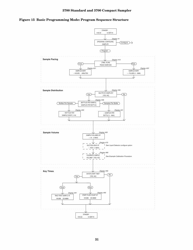
3700 Standard and 3700 Compact Sampler
31
Figure 15 Basic Programming Mode: Program Sequence Structure
[PROGRAM, CONFIGURE]
SAMPLER
Time[TIME, FLOW]
PACED SAMPLING
SAMPLE EVERY
-- HOURS -- MINUTES
Flow
SAMPLE EVERY
---- PULSES (1 - 9999)
. . . STANDBY . . .
9:50:34 12-SEP-91
. . . STANDBY . . .
9:54:22 12-SEP-91
Display #1
Display #10
Display #22Display #21
Program
Configure
Display #50
No
SAMPLE VOLUMES OF
--- ml (1-MAX)
SUCTION HEAD OF
-- FEET (1-MAX)
Display #70
Display #80
CALIBRATE SAMPLE
VOLUME? [YES, NO]See Example Calibration Procedure
Display #90
ENTER START TIME?
[YES, NO]Yes
FlowTime
TAKE FIRST SAMPLE AT
HH:MM DD-MMM
START FLOW COUNT AT
HH:MM DD-MMM
Display #92
MULTIPLEX SAMPLES?
[YES, NO]
[BOTTLES PER SAMPLE,
SAMPLES PER BOTTLE]
-- BOTTLES PER
SAMPLE EVENT (1-24)-- SAMPLES PER
BOTTLE (1 - MAX)
Samples Per BottleBottles Per Sample
Yes No
Display #35
Display #36
Display #31Display #30
See Liquid Detector configure option
Sample Pacing
Sample Distribution
Sample Volume
Key Times
Display #91
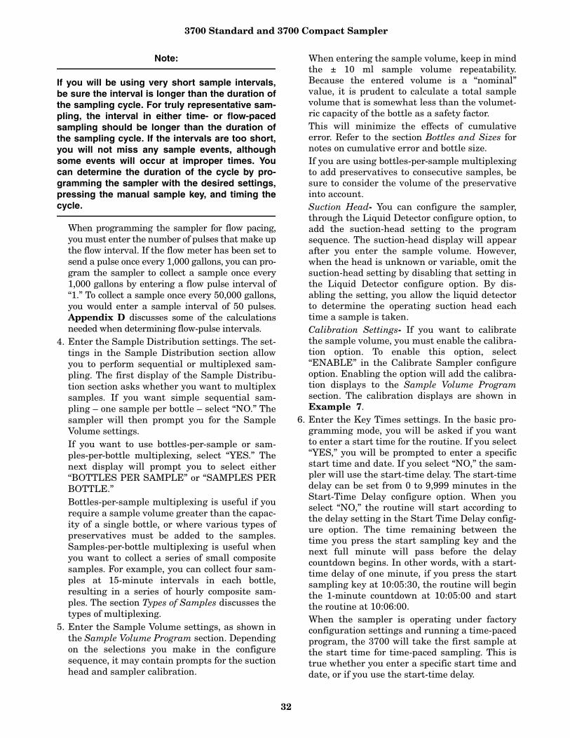
3700 Standard and 3700 Compact Sampler
32
Note:
If you will be using very short sample intervals,be sure the interval is longer than the duration ofthe sampling cycle. For truly representative sam-pling, the interval in either time- or flow-pacedsampling should be longer than the duration ofthe sampling cycle. If the intervals are too short,you will not miss any sample events, althoughsome events will occur at improper times. Youcan determine the duration of the cycle by pro-gramming the sampler with the desired settings,pressing the manual sample key, and timing thecycle.
When programming the sampler for flow pacing,you must enter the number of pulses that make upthe flow interval. If the flow meter has been set tosend a pulse once every 1,000 gallons, you can pro-gram the sampler to collect a sample once every1,000 gallons by entering a flow pulse interval of“1.” To collect a sample once every 50,000 gallons,you would enter a sample interval of 50 pulses.Appendix D discusses some of the calculationsneeded when determining flow-pulse intervals.
4. Enter the Sample Distribution settings. The set-tings in the Sample Distribution section allowyou to perform sequential or multiplexed sam-pling. The first display of the Sample Distribu-tion section asks whether you want to multiplexsamples. If you want simple sequential sam-pling – one sample per bottle – select “NO.” Thesampler will then prompt you for the SampleVolume settings. If you want to use bottles-per-sample or sam-ples-per-bottle multiplexing, select “YES.” Thenext display will prompt you to select either“BOTTLES PER SAMPLE” or “SAMPLES PERBOTTLE.” Bottles-per-sample multiplexing is useful if yourequire a sample volume greater than the capac-ity of a single bottle, or where various types ofpreservatives must be added to the samples.Samples-per-bottle multiplexing is useful whenyou want to collect a series of small compositesamples. For example, you can collect four sam-ples at 15-minute intervals in each bottle,resulting in a series of hourly composite sam-ples. The section Types of Samples discusses thetypes of multiplexing.
5. Enter the Sample Volume settings, as shown inthe Sample Volume Program section. Dependingon the selections you make in the configuresequence, it may contain prompts for the suctionhead and sampler calibration.
When entering the sample volume, keep in mindthe ± 10 ml sample volume repeatability.Because the entered volume is a “nominal”value, it is prudent to calculate a total samplevolume that is somewhat less than the volumet-ric capacity of the bottle as a safety factor. This will minimize the effects of cumulativeerror. Refer to the section Bottles and Sizes fornotes on cumulative error and bottle size. If you are using bottles-per-sample multiplexingto add preservatives to consecutive samples, besure to consider the volume of the preservativeinto account.Suction Head- You can configure the sampler,through the Liquid Detector configure option, toadd the suction-head setting to the programsequence. The suction-head display will appearafter you enter the sample volume. However,when the head is unknown or variable, omit thesuction-head setting by disabling that setting inthe Liquid Detector configure option. By dis-abling the setting, you allow the liquid detectorto determine the operating suction head eachtime a sample is taken. Calibration Settings- If you want to calibratethe sample volume, you must enable the calibra-tion option. To enable this option, select“ENABLE” in the Calibrate Sampler configureoption. Enabling the option will add the calibra-tion displays to the Sample Volume Programsection. The calibration displays are shown inExample 7.
6. Enter the Key Times settings. In the basic pro-gramming mode, you will be asked if you wantto enter a start time for the routine. If you select“YES,” you will be prompted to enter a specificstart time and date. If you select “NO,” the sam-pler will use the start-time delay. The start-timedelay can be set from 0 to 9,999 minutes in theStart-Time Delay configure option. When youselect “NO,” the routine will start according tothe delay setting in the Start Time Delay config-ure option. The time remaining between thetime you press the start sampling key and thenext full minute will pass before the delaycountdown begins. In other words, with a start-time delay of one minute, if you press the startsampling key at 10:05:30, the routine will beginthe 1-minute countdown at 10:05:00 and startthe routine at 10:06:00. When the sampler is operating under factoryconfiguration settings and running a time-pacedprogram, the 3700 will take the first sample atthe start time for time-paced sampling. This istrue whether you enter a specific start time anddate, or if you use the start-time delay.

3700 Standard and 3700 Compact Sampler
33
For flow-paced sampling, however, the flowpulse countdown will begin at the start time andthe first sample will be taken when the count-down reaches zero. Refer to the discussion onthe Flow Mode option in the Nonuniform Timesection for additional information.
7. The sampler automatically returns to standby.8. From standby, start the routine by pressing the
start sampling key. This places the sampler intothe run state. If you to start the routine afterthe programmed start time, the sampler willallow you to reprogram the start time.
9. Use the run state displays to monitor the sam-pler’s progress.
Before programming the sampler – Especiallyif you are unfamiliar with the settings used in theprevious routine, or if the settings have beenchanged, verify the configure-option settings. Youmust change the settings if they do not match yourbottle size or the suction line used with your unit.Entries suggested in this example configure thesampler for 24 1000-ml bottles and a 10-foot lengthof 3/8-inch vinyl suction line, enable the liquiddetector, and select the basic programming mode.Procedures for reinitialization of the program set-tings and configure options to factory settings areplaced in Steps 22 through 28 in Example 1.
Example 1 Checking the configure option settings.
If the sampler is not already on, press the ON/OFF key to turn it on. The standby display shown here willappear. Press the ENTER/PROGRAM key to access the interactive state. The next display you’ll see is shown inStep 2.
Step 1. . . STANDBY . . .
10:34:50 19-JUN-91
Access the configure sequence by selecting “CONFIGURE.” Select “CONFIGURE” by pressing the RIGHT
ARROW key once. When “CONFIGURE” blinks, accept the selection by pressing the ENTER/PROGRAM key.
Step 2[PROGRAM, CONFIGURE]
SAMPLER
The first option displayed is the Set Clock configure option. If the time displayed on the LCD in the standbymessage is not correct, reset the time with the Set Clock configure option. Press the ENTER/PROGRAM key toaccess the Set Clock input display.
Step 3 SELECT OPTION: (← →)SET CLOCK
Use this display to reset the time. Five entries are required. The LEFT ARROW and RIGHT ARROW keys can beused to move back and forth between each of the five entries. Use the arrow keys until the entry you want tochange blinks. Type in the new time or date; press the ENTER/PROGRAM key to accept it. Press the RIGHT
ARROW or ENTER/PROGRAM key on the last entry to store the values and advance to the next display
Step 4HH:MM DD-MM-YY10:35:20 19-06-91
To verify the Bottles and Sizes settings, press the ENTER/PROGRAM key. The display shown in Step 5 willappear.
Step 5SELECT OPTION: (← →)
BOTTLES AND SIZES
Select “PORTABLE” or “REFRIG” depending upon which model you have. Enter PORTABLE for either the3700 Standard or Compact.
Step 6{PORTABLE, REFRIG
SAMPLER

3700 Standard and 3700 Compact Sampler
34
For the purposes of this example, select “24” when you are using the 24-bottle base. Use the arrow keys until“24” blinks, then press the ENTER/PROGRAM key. Select “1” when you are using a single-bottle for compositesampling.
Step 7{1, 4, 12, 24}
BOTTLES
Enter the bottle size here. Enter “350” for the 350 ml glass bottles, “1000” for plastic bottles, for example. Pressthe ENTER/PROGRAM key. If you enter a number that exceeds the maximum standard bottle size (15,000), themessage, “WARNING: STANDARD BTL VOLUME EXCEEDED!,” will display for a short time. The samplerwill then prompt you to confirm the volume entered. This prompt is displayed in Step 9.
Step 8BOTTLE VOLUME IS
1000 ml
Select “YES” if you want to use the nonstandard bottle volume. Select “NO” if you want to revise the entry. Thedisplay shown in step 8 will reappear; use it to enter the revised bottle volume. Press the ENTER/PROGRAM keyto accept the entry and advance to step 10
Step 91001 ml! . . . ARE YOU
SURE? {YES, NO}
Press the ENTER/PROGRAM key at this display to access the Suction-Line input displays shown in steps 11 to 13.
Step 10 SELECT OPTION: (← →)SUCTION LINE
Select “1/4” if you are using 1/4-inch suction line, “3/8” if you are using 3/8-inch suction line. Press the ENTER/PROGRAM key to accept the selection. If you select “1/4,” you will not see the display shown in step 12; insteadyou will be prompted for the suction-line length, as shown in step 13. (You do not need to specify vinyl line typebecause only 1/4-inch suction line is available.)
Step 11 SUCTION LINE ID IS{ 1/4, 3/8} INCH
This display appears when you have selected “3/8” in step 11. Select “VINYL” if you are using vinyl suctionline, “TEFLON” if you are using Teflon suction line. Press the ENTER/PROGRAM key to accept the selection
Step 12 SUCTION LINE IS{VINYL, TEFLON}
Enter the length of the suction line. Do not include the tube coupling or the strainer in the length. Press theENTER/PROGRAM key to accept the entry and move to step 14. If you change the suction line settings, the “. . .CALCULATING . . . PUMP TABLE VALUES” message will appear for a short time
Step 13SUCTION LINE LENGTH
IS 10 FEET (3 - 99)
Press the ENTER/PROGRAM key at this display to access the Liquid Detector input displays shown in steps 15 to 18.
Step 14SELECT OPTION: (← →)
LIQUID DETECTOR
Select “ENABLE” to turn on the Liquid Detector on, “DISABLE” to turn off the Liquid Detector. For the pur-poses of the following examples, select “ENABLE.” Press the ENTER/PROGRAM key to accept the selection. Youshould normally leave the detector enabled unless you suspect it is malfunctioning. If you disable the detector,you will need to enter the suction head in the program sequence.
Step 15[ENABLE, DISABLE]LIQUID DETECTOR
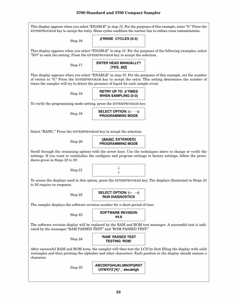
3700 Standard and 3700 Compact Sampler
35
This display appears when you select “ENABLE” in step 15. For the purposes of this example, enter “0.” Press theENTER/PROGRAM key to accept the entry. Rinse cycles condition the suction line to reduce cross contamination.
Step 160 RINSE CYCLES (0-3)
This display appears when you select “ENABLE” in step 15. For the purposes of the following examples, select“NO” to omit the setting. Press the ENTER/PROGRAM key to accept the selection.
Step 17ENTER HEAD MANUALLY?
[YES, NO]
This display appears when you select “ENABLE” in step 15. For the purposes of this example, set the numberof retries to “0.” Press the ENTER/PROGRAM key to accept the entry. This setting determines the number oftimes the sampler will try to detect the presence of liquid for each sample event.
Step 18RETRY UP TO 0 TIMESWHEN SAMPLING (0-3)
To verify the programming mode setting, press the ENTER/PROGRAM key.
Step 19SELECT OPTION: (← →)PROGRAMMING MODE
Select “BASIC.” Press the ENTER/PROGRAM key to accept the selection
Step 20[BASIC, EXTENDED]
PROGRAMMING MODE
Scroll through the remaining options with the arrow keys. Use the techniques above to change or verify thesettings. If you want to reinitialize the configure and program settings to factory settings, follow the proce-dures given in Steps 22 to 28.
Step 21↓↓
To access the displays used in this option, press the ENTER/PROGRAM key. The displays illustrated in Steps 23to 26 require no response.
Step 22 SELECT OPTION: (← →)RUN DIAGNOSTICS
The sampler displays the software revision number for a short period of time.
Step 23SOFTWARE REVISION
#4.6
The software revision display will be replaced by the RAM and ROM test messages. A successful test is indi-cated by the messages “RAM PASSED TEST” and “ROM PASSED TEST.”
Step 24‘RAM’ PASSED TEST
TESTING ‘ROM’
After successful RAM and ROM tests, the sampler will then test the LCD by first filling the display with solidrectangles and then printing the alphabet and other characters. Each position in the display should contain acharacter.
Step 25 ABCDEFGHIJKLMNOPQRSTUVWXYZ [¥]^_`abcdefgh
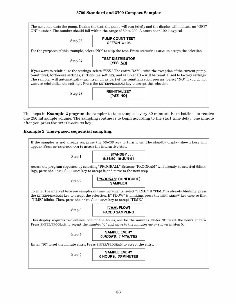
3700 Standard and 3700 Compact Sampler
36
The steps in Example 2 program the sampler to take samples every 30 minutes. Each bottle is to receiveone 250 ml sample volume. The sampling routine is to begin according to the start time delay: one minuteafter you press the START SAMPLING key.
Example 2 Time-paced sequential sampling.
The next step tests the pump. During the test, the pump will run briefly and the display will indicate an “OFF/ON” number. The number should fall within the range of 50 to 200. A count near 100 is typical.
Step 26PUMP COUNT TEST
OFF/ON = 105
For the purposes of this example, select “NO” to skip the test. Press ENTER/PROGRAM to accept the selection
Step 27 TEST DISTRIBUTOR[YES, NO]
If you want to reinitialize the settings, select “YES.” The entire RAM – with the exception of the current pump-count total, bottle-size settings, suction-line settings, and sampler ID – will be reinitialized to factory settings.The sampler will automatically turn itself off as part of the reinitialization process. Select “NO” if you do notwant to reinitialize the settings. Press the ENTER/PROGRAM key to accept the selection
Step 28REINITIALIZE?
[YES, NO]
If the sampler is not already on, press the ON/OFF key to turn it on. The standby display shown here willappear. Press ENTER/PROGRAM to access the interactive state
Step 1 . . . STANDBY . . .5:34:50 19-JUN-91
Access the program sequence by selecting “PROGRAM.” Because “PROGRAM” will already be selected (blink-ing), press the ENTER/PROGRAM key to accept it and move to the next step.
Step 2[PROGRAM, CONFIGURE]
SAMPLER
To enter the interval between samples in time increments, select “TIME.” If “TIME” is already blinking, pressthe ENTER/PROGRAM key to accept the selection. If “FLOW” is blinking, press the LEFT ARROW key once so that“TIME” blinks. Then, press the ENTER/PROGRAM key to accept “TIME.”
Step 3[TIME, FLOW]
PACED SAMPLING
This display requires two entries: one for the hours, one for the minutes. Enter “0” to set the hours at zero.Press ENTER/PROGRAM to accept the number “0” and move to the minutes entry shown in step 5.
Step 4SAMPLE EVERY
0 HOURS, 1 MINUTES
Enter “30” to set the minute entry. Press ENTER/PROGRAM to accept the entry.
Step 5SAMPLE EVERY
0 HOURS, 30 MINUTES
3700 Standard and 3700 Compact Sampler
37
For this example, select “NO.”Press the ENTER/PROGRAM key to accept the entry. If you select “YES” in responseto this question, you can select bottles-per-sample or samples-per-bottle multiplexing for your routine.
Step 6MULTIPLEX SAMPLES?
[YES, NO]
Enter the sample volume: “250.” Press ENTER/PROGRAM to accept the entry.
Step 7 SAMPLE VOLUMES OF250 ml (10 - 1000)
Because this sampling routine does not require a specific start time, use the arrow keys to select “NO.” Pressthe ENTER/PROGRAM key to accept the entry. If you select “YES,” you can enter a specific start time and date forthe routine.
Step 8ENTER START TIME?
[YES, NO]
After this message displays briefly, the sampler will automatically return to the standby state.
Step 9PROGRAMMING SEQUENCE
COMPLETE
After you properly install the sampler, press the START SAMPLING key to run the program.
Step 10. . . STANDBY . . .
5:42:23 19-JUN-91
To start the sampling routine with the first bottle, accept the blinking “1” by pressing the ENTER/PROGRAM key.If you want to start the routine with another bottle, enter the starting bottle number.
Step 11START SAMPLING BOTTLE 1 (1-24)
This display appears as the sampler counts down the time remaining to the start time. The first line reportsthe bottle which will receive the next sample volume. The second line reports the start time at the left and thecurrent time on the right.
Step 12BOTTLE 1
AT 5:44 5:42:33
When the start time arrives, the sampler will take the first sample. The sample event cycle begins with a pre-sample purge. During the purge, the display indicates the number of the bottle that will receive the samplevolume.
Step 13 BOTTLE 1
As soon as the pump runs forward to deliver the sample volume, the message on the second line appears. Thismessage remains through the post-sample purge.
BOTTLE 1PUMPING 250 ml
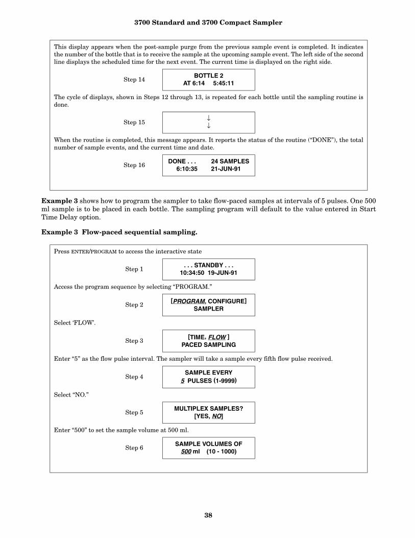
3700 Standard and 3700 Compact Sampler
38
Example 3 shows how to program the sampler to take flow-paced samples at intervals of 5 pulses. One 500ml sample is to be placed in each bottle. The sampling program will default to the value entered in StartTime Delay option.
Example 3 Flow-paced sequential sampling.
This display appears when the post-sample purge from the previous sample event is completed. It indicatesthe number of the bottle that is to receive the sample at the upcoming sample event. The left side of the secondline displays the scheduled time for the next event. The current time is displayed on the right side.
Step 14BOTTLE 2
AT 6:14 5:45:11
The cycle of displays, shown in Steps 12 through 13, is repeated for each bottle until the sampling routine isdone.
Step 15↓↓
When the routine is completed, this message appears. It reports the status of the routine (“DONE”), the totalnumber of sample events, and the current time and date.
Step 16DONE . . . 24 SAMPLES
6:10:35 21-JUN-91
Press ENTER/PROGRAM to access the interactive state
Step 1. . . STANDBY . . .
10:34:50 19-JUN-91
Access the program sequence by selecting “PROGRAM.”
Step 2[PROGRAM, CONFIGURE]
SAMPLER
Select ‘FLOW’.
Step 3[TIME, FLOW ]
PACED SAMPLING
Enter “5” as the flow pulse interval. The sampler will take a sample every fifth flow pulse received.
Step 4SAMPLE EVERY
5 PULSES (1-9999)
Select “NO.”
Step 5MULTIPLEX SAMPLES?
[YES, NO]
Enter “500” to set the sample volume at 500 ml.
Step 6SAMPLE VOLUMES OF
500 ml (10 - 1000)
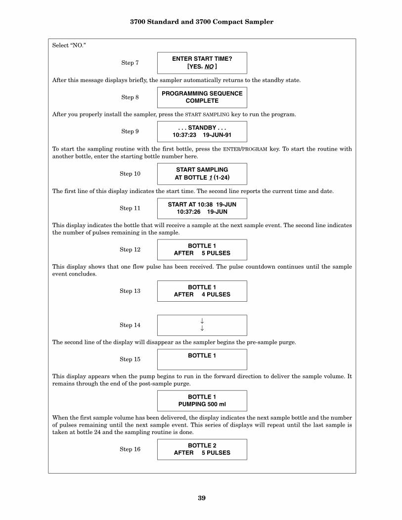
3700 Standard and 3700 Compact Sampler
39
Select “NO.”
Step 7ENTER START TIME?
[YES, NO ]
After this message displays briefly, the sampler automatically returns to the standby state.
Step 8PROGRAMMING SEQUENCE
COMPLETE
After you properly install the sampler, press the START SAMPLING key to run the program.
Step 9 . . . STANDBY . . .10:37:23 19-JUN-91
To start the sampling routine with the first bottle, press the ENTER/PROGRAM key. To start the routine withanother bottle, enter the starting bottle number here.
Step 10START SAMPLINGAT BOTTLE 1 (1-24)
The first line of this display indicates the start time. The second line reports the current time and date.
Step 11 START AT 10:38 19-JUN10:37:26 19-JUN
This display indicates the bottle that will receive a sample at the next sample event. The second line indicatesthe number of pulses remaining in the sample.
Step 12 BOTTLE 1AFTER 5 PULSES
This display shows that one flow pulse has been received. The pulse countdown continues until the sampleevent concludes.
Step 13BOTTLE 1
AFTER 4 PULSES
Step 14 ↓↓
The second line of the display will disappear as the sampler begins the pre-sample purge.
Step 15BOTTLE 1
This display appears when the pump begins to run in the forward direction to deliver the sample volume. Itremains through the end of the post-sample purge.
BOTTLE 1PUMPING 500 ml
When the first sample volume has been delivered, the display indicates the next sample bottle and the numberof pulses remaining until the next sample event. This series of displays will repeat until the last sample istaken at bottle 24 and the sampling routine is done.
Step 16 BOTTLE 2AFTER 5 PULSES

3700 Standard and 3700 Compact Sampler
40
Example 4 shows samples-per-bottle multiplexed sampling. Samples are taken every 15 minutes. Eachbottle receives four sample volumes of 200 ml each, so that bottles are switched every hour. The samplingroutine is to start at 6:00 AM on the following day.
Example 4 Time-paced multiplexed (samples-per-bottle) sampling.
Step 17 ↓↓
This display informs you that the sampling routine is completed. The number of sample events displays in theupper right corner. The second line indicates the current time and date.
Step 18 DONE . . . 24 SAMPLES22:48:32 20-JUN-91
Press ENTER/PROGRAM to access the interactive state.
Step 1. . . STANDBY . . .
10:34:50 19-JUN-91
Access the program sequence by selecting “PROGRAM.”
Step 2[PROGRAM, CONFIGURE]
SAMPLER
Select “TIME.”
Step 3[TIME, FLOW]
PACED SAMPLING
Enter “0” to set the hours at zero. Press ENTER/PROGRAM to store the number “0” and move to the minutesentry.
Step 4SAMPLE EVERY
0 HOURS,1 MINUTES
Enter “15” to set the minutes entry to 15.
Step 5SAMPLE EVERY
0 HOURS,15 MINUTES
Select “YES” to set up the samples-per-bottle multiplexing.
Step 6MULTIPLEX SAMPLES?
[YES, NO]
Select “SAMPLES PER BOTTLE.”
Step 7[BOTTLES PER SAMPLE,SAMPLES PER BOTTLE]
Enter “4” to set the number of samples per bottle to 4.
Step 84 SAMPLES PERBOTTLE (1 - 50)
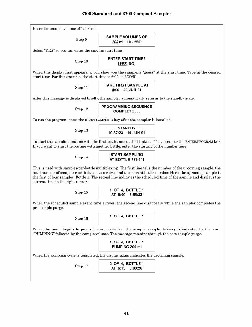
3700 Standard and 3700 Compact Sampler
41
Enter the sample volume of “200” ml.
Step 9SAMPLE VOLUMES OF
200 ml (10 - 250)
Select “YES” so you can enter the specific start time.
Step 10ENTER START TIME?
[YES, NO]
When this display first appears, it will show you the sampler’s “guess” at the start time. Type in the desiredstart time. For this example, the start time is 6:00 on 6/20/91.
Step 11 TAKE FIRST SAMPLE AT6:00 20-JUN-91
After this message is displayed briefly, the sampler automatically returns to the standby state.
Step 12PROGRAMMING SEQUENCE
COMPLETE . . .
To run the program, press the START SAMPLING key after the sampler is installed.
Step 13. . . STANDBY . . .
10:37:23 19-JUN-91
To start the sampling routine with the first bottle, accept the blinking “1” by pressing the ENTER/PROGRAM key.If you want to start the routine with another bottle, enter the starting bottle number here.
Step 14START SAMPLINGAT BOTTLE 1 (1-24)
This is used with samples-per-bottle multiplexing. The first line tells the number of the upcoming sample, thetotal number of samples each bottle is to receive, and the current bottle number. Here, the upcoming sample isthe first of four samples, Bottle 1. The second line indicates the scheduled time of the sample and displays thecurrent time in the right corner.
Step 151 OF 4, BOTTLE 1AT 6:00 5:55:33
When the scheduled sample event time arrives, the second line disappears while the sampler completes thepre-sample purge.
Step 161 OF 4, BOTTLE 1
When the pump begins to pump forward to deliver the sample, sample delivery is indicated by the word“PUMPING” followed by the sample volume. The message remains through the post-sample purge.
1 OF 4, BOTTLE 1PUMPING 200 ml
When the sampling cycle is completed, the display again indicates the upcoming sample.
Step 172 OF 4, BOTTLE 1AT 6:15 6:00:26
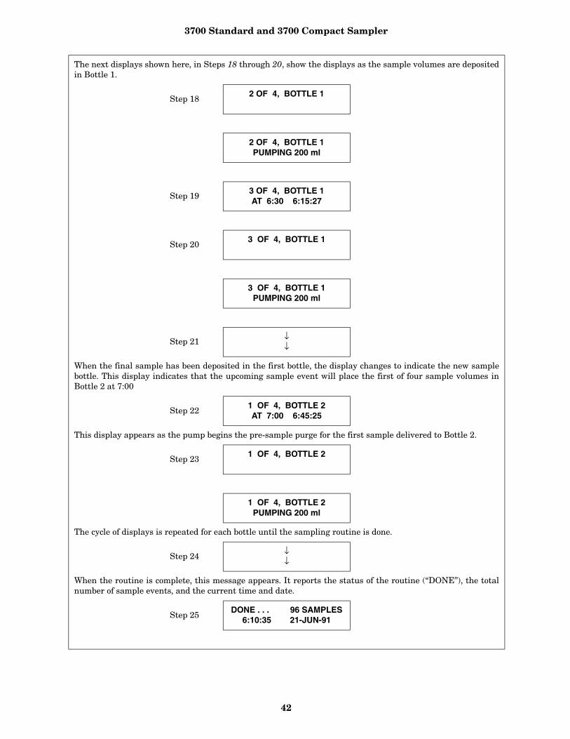
3700 Standard and 3700 Compact Sampler
42
The next displays shown here, in Steps 18 through 20, show the displays as the sample volumes are depositedin Bottle 1.
Step 182 OF 4, BOTTLE 1
2 OF 4, BOTTLE 1PUMPING 200 ml
Step 193 OF 4, BOTTLE 1AT 6:30 6:15:27
Step 203 OF 4, BOTTLE 1
3 OF 4, BOTTLE 1PUMPING 200 ml
Step 21↓↓
When the final sample has been deposited in the first bottle, the display changes to indicate the new samplebottle. This display indicates that the upcoming sample event will place the first of four sample volumes inBottle 2 at 7:00
Step 221 OF 4, BOTTLE 2AT 7:00 6:45:25
This display appears as the pump begins the pre-sample purge for the first sample delivered to Bottle 2.
Step 23 1 OF 4, BOTTLE 2
1 OF 4, BOTTLE 2PUMPING 200 ml
The cycle of displays is repeated for each bottle until the sampling routine is done.
Step 24↓↓
When the routine is complete, this message appears. It reports the status of the routine (“DONE”), the totalnumber of sample events, and the current time and date.
Step 25DONE . . . 96 SAMPLES
6:10:35 21-JUN-91
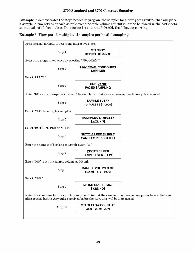
3700 Standard and 3700 Compact Sampler
43
Example 5 demonstrates the steps needed to program the sampler for a flow-paced routine that will placea sample in two bottles at each sample event. Sample volumes of 500 ml are to be placed in the bottle setsat intervals of 10 flow-pulses. The routine is to start at 5:00 AM, the following morning.
Example 5 Flow-paced multiplexed (samples-per-bottle) sampling.
Press ENTER/PROGRAM to access the interactive state.
Step 1. . . STANDBY . . .
10:34:50 19-JUN-91
Access the program sequence by selecting “PROGRAM.”
Step 2[PROGRAM, CONFIGURE]
SAMPLER
Select “FLOW.”
Step 3[TIME, FLOW]
PACED SAMPLING
Enter “10” as the flow--pulse interval. The sampler will take a sample every tenth flow pulse received.
Step 4SAMPLE EVERY
10 PULSES (1-9999)
Select “YES” to multiplex samples.
Step 5 MULTIPLEX SAMPLES?[YES, NO]
Select “BOTTLES PER SAMPLE.”
Step 6[BOTTLES PER SAMPLE,SAMPLES PER BOTTLE]
Enter the number of bottles per sample event: “2.”
Step 72 BOTTLES PER
SAMPLE EVENT (1-24)
Enter “500” to set the sample volume at 500 ml.
Step 8SAMPLE VOLUMES OF
500 ml (10 - 1000)
Select “YES.”
Step 9ENTER START TIME?
[YES, NO]
Enter the start time for the sampling routine. Note that the sampler may receive flow pulses before the sam-pling routine begins. Any pulses received before the start time will be disregarded.
Step 10 START FLOW COUNT AT5:00 20-06 JUN
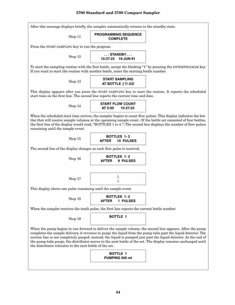
3700 Standard and 3700 Compact Sampler
44
After this message displays briefly, the sampler automatically returns to the standby state.
Step 11 PROGRAMMING SEQUENCECOMPLETE
Press the START SAMPLING key to run the program.
Step 12. . . STANDBY . . .
10:37:23 19-JUN-91
To start the sampling routine with the first bottle, accept the blinking “1” by pressing the ENTER/PROGRAM key.If you want to start the routine with another bottle, enter the starting bottle number.
Step 13START SAMPLINGAT BOTTLE 1 (1-23)
This display appears after you press the START SAMPLING key to start the routine. It reports the scheduledstart time on the first line. The second line reports the current time and date.
Step 14 START FLOW COUNT AT 5:00 10:37:23
When the scheduled start time arrives, the sampler begins to count flow pulses. This display indicates the bot-tles that will receive sample volumes at the upcoming sample event. (If the bottle set consisted of four bottles,the first line of the display would read, “BOTTLES 1 to 4.”) The second line displays the number of flow pulsesremaining until the sample event.
Step 15BOTTLES 1- 2
AFTER 10 PULSES
The second line of the display changes as each flow pulse is received.
Step 16BOTTLES 1- 2
AFTER 9 PULSES
Step 17↓↓
This display shows one pulse remaining until the sample event.
Step 18 BOTTLES 1- 2AFTER 1 PULSES
When the sampler receives the tenth pulse, the first line reports the current bottle number.
Step 19BOTTLE 1
When the pump begins to run forward to deliver the sample volume, the second line appears. After the pumpcompletes the sample delivery, it reverses to purge the liquid from the pump tube past the liquid detector. Thesuction line is not completely purged; instead, the liquid is pumped just past the liquid detector. At the end ofthe pump-tube purge, the distributor moves to the next bottle of the set. The display remains unchanged untilthe distributor relocates to the next bottle of the set.
BOTTLE 1PUMPING 500 ml
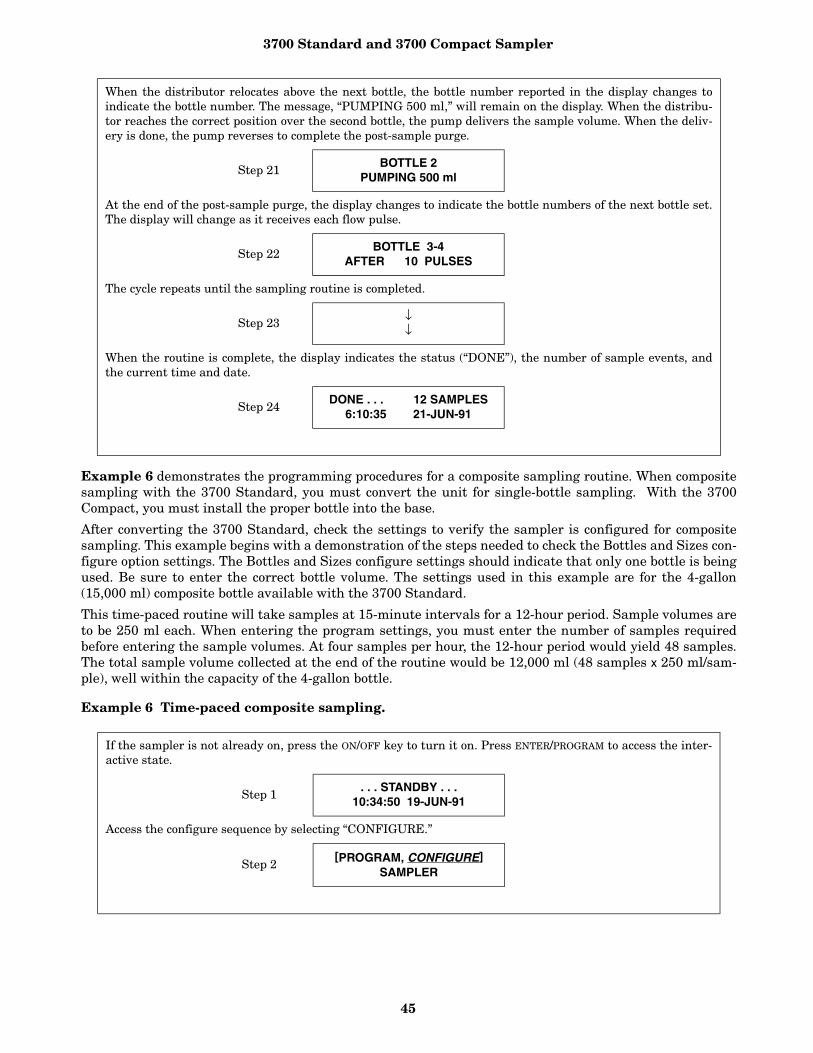
3700 Standard and 3700 Compact Sampler
45
Example 6 demonstrates the programming procedures for a composite sampling routine. When compositesampling with the 3700 Standard, you must convert the unit for single-bottle sampling. With the 3700Compact, you must install the proper bottle into the base.
After converting the 3700 Standard, check the settings to verify the sampler is configured for compositesampling. This example begins with a demonstration of the steps needed to check the Bottles and Sizes con-figure option settings. The Bottles and Sizes configure settings should indicate that only one bottle is beingused. Be sure to enter the correct bottle volume. The settings used in this example are for the 4-gallon(15,000 ml) composite bottle available with the 3700 Standard.
This time-paced routine will take samples at 15-minute intervals for a 12-hour period. Sample volumes areto be 250 ml each. When entering the program settings, you must enter the number of samples requiredbefore entering the sample volumes. At four samples per hour, the 12-hour period would yield 48 samples.The total sample volume collected at the end of the routine would be 12,000 ml (48 samples x 250 ml/sam-ple), well within the capacity of the 4-gallon bottle.
Example 6 Time-paced composite sampling.
When the distributor relocates above the next bottle, the bottle number reported in the display changes toindicate the bottle number. The message, “PUMPING 500 ml,” will remain on the display. When the distribu-tor reaches the correct position over the second bottle, the pump delivers the sample volume. When the deliv-ery is done, the pump reverses to complete the post-sample purge.
Step 21 BOTTLE 2PUMPING 500 ml
At the end of the post-sample purge, the display changes to indicate the bottle numbers of the next bottle set.The display will change as it receives each flow pulse.
Step 22 BOTTLE 3-4AFTER 10 PULSES
The cycle repeats until the sampling routine is completed.
Step 23↓↓
When the routine is complete, the display indicates the status (“DONE”), the number of sample events, andthe current time and date.
Step 24DONE . . . 12 SAMPLES
6:10:35 21-JUN-91
If the sampler is not already on, press the ON/OFF key to turn it on. Press ENTER/PROGRAM to access the inter-active state.
Step 1. . . STANDBY . . .
10:34:50 19-JUN-91
Access the configure sequence by selecting “CONFIGURE.”
Step 2[PROGRAM, CONFIGURE]
SAMPLER
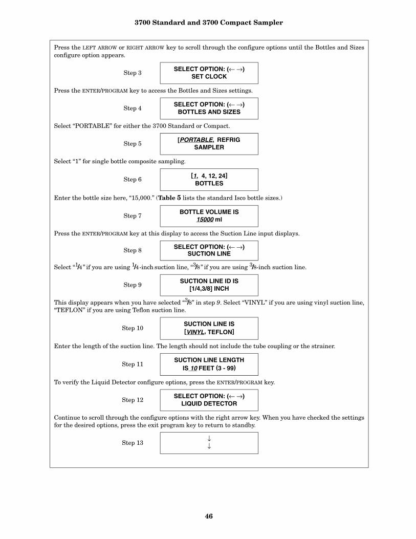
3700 Standard and 3700 Compact Sampler
46
Press the LEFT ARROW or RIGHT ARROW key to scroll through the configure options until the Bottles and Sizesconfigure option appears.
Step 3 SELECT OPTION: (← →)SET CLOCK
Press the ENTER/PROGRAM key to access the Bottles and Sizes settings.
Step 4SELECT OPTION: (← →)
BOTTLES AND SIZES
Select “PORTABLE” for either the 3700 Standard or Compact.
Step 5[PORTABLE, REFRIG
SAMPLER
Select “1” for single bottle composite sampling.
Step 6[1, 4, 12, 24]
BOTTLES
Enter the bottle size here, “15,000.” (Table 5 lists the standard Isco bottle sizes.)
Step 7 BOTTLE VOLUME IS15000 ml
Press the ENTER/PROGRAM key at this display to access the Suction Line input displays.
Step 8 SELECT OPTION: (← →)SUCTION LINE
Select “1/4” if you are using 1/4-inch suction line, “3/8” if you are using 3/8-inch suction line.
Step 9 SUCTION LINE ID IS[1/4,3/8] INCH
This display appears when you have selected “3/8” in step 9. Select “VINYL” if you are using vinyl suction line,“TEFLON” if you are using Teflon suction line.
Step 10SUCTION LINE IS[VINYL, TEFLON]
Enter the length of the suction line. The length should not include the tube coupling or the strainer.
Step 11SUCTION LINE LENGTH
IS 10 FEET (3 - 99)
To verify the Liquid Detector configure options, press the ENTER/PROGRAM key.
Step 12SELECT OPTION: (← →)
LIQUID DETECTOR
Continue to scroll through the configure options with the right arrow key. When you have checked the settingsfor the desired options, press the exit program key to return to standby.
Step 13↓↓
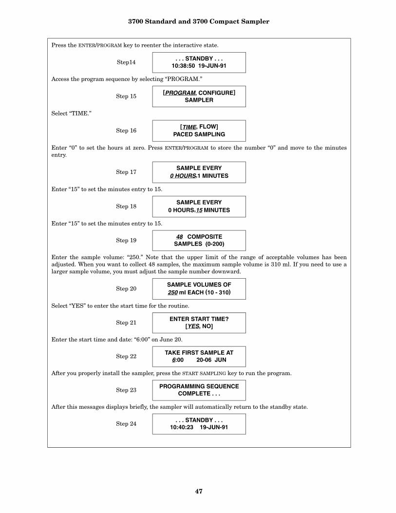
3700 Standard and 3700 Compact Sampler
47
Press the ENTER/PROGRAM key to reenter the interactive state.
Step14. . . STANDBY . . .
10:38:50 19-JUN-91
Access the program sequence by selecting “PROGRAM.”
Step 15[PROGRAM, CONFIGURE]
SAMPLER
Select “TIME.”
Step 16[TIME, FLOW]
PACED SAMPLING
Enter “0” to set the hours at zero. Press ENTER/PROGRAM to store the number “0” and move to the minutesentry.
Step 17SAMPLE EVERY
0 HOURS,1 MINUTES
Enter “15” to set the minutes entry to 15.
Step 18SAMPLE EVERY
0 HOURS,15 MINUTES
Enter “15” to set the minutes entry to 15.
Step 19 48 COMPOSITESAMPLES (0-200)
Enter the sample volume: “250.” Note that the upper limit of the range of acceptable volumes has beenadjusted. When you want to collect 48 samples, the maximum sample volume is 310 ml. If you need to use alarger sample volume, you must adjust the sample number downward.
Step 20SAMPLE VOLUMES OF250 ml EACH (10 - 310)
Select “YES” to enter the start time for the routine.
Step 21 ENTER START TIME?[YES, NO]
Enter the start time and date: “6:00” on June 20.
Step 22TAKE FIRST SAMPLE AT
6:00 20-06 JUN
After you properly install the sampler, press the START SAMPLING key to run the program.
Step 23PROGRAMMING SEQUENCE
COMPLETE . . .
After this messages displays briefly, the sampler will automatically return to the standby state.
Step 24 . . . STANDBY . . .10:40:23 19-JUN-91

3700 Standard and 3700 Compact Sampler
48
Example 7 shows how to calibrate the sampler for a 200-ml sample volume. You must enable the CalibrateSampler configure option in the configure sequence before the calibration displays shown below appear.
Even without calibrating, the 3700 Sampler delivers accurate sample volumes. If your sample volumes varysignificantly with the entered values, check the suction line first. Be sure the line slopes continuously down-hill and is draining completely after each pumping cycle. Then, check the suction-line entries in the configuresequence to see that they are accurate. The calibration procedure is intended to be for “fine tuning” only.
After you enter the sample volume actually delivered, as shown in Step 8, all subsequent sample volumesdelivered will be adjusted to correct for the difference between the expected sample volume and the actualvolume entered. Clear the adjustment by changing a suction line entry in the Suction Line configure optionor by reinitialization of the sampler.
Because the sample volume can be calibrated to ± 10 ml, use a graduated cylinder to facilitate measure-ment. Isco offers a graduated cylinder and spare bottles as accessories from the factory. Refer to the Acces-sories List at the back of this manual for details.
The calibration pump cycle will include rinse cycles and retries, if the sampler is configured to performthem. This ensures that the calibration procedure includes the pump cycle used while running the sam-pling program.
The first line of this display indicates the number of the upcoming sample event and the total number of pro-grammed samples. The second line indicates the scheduled time of the upcoming event followed by the cur-rent time.
Step 25SAMPLE 1 OF 48
AT 6:00 5:50:43
When the time to the next sample event has elapsed and the sampler has initiated the sample event, the sam-pling cycle begins.
Step 26SAMPLE 1 OF 48
When the pump reverses for the pre-sample purge, the second line disappears. At the end of the pre-samplepurge, the pump runs forward to deliver the sample, and the second line appears on the display. This displayremains through the end of the post-sample purge.
SAMPLE 1 OF 48PUMPING 250 ml
At the end of the sample event, the display changes to indicate the number and time of the next event. Thelower right corner reports the current time.
Step 27 SAMPLE 2 OF 48AT 6:15 6:00:33
The cycle repeats for the remainder of the sampling routine.
Step 28SAMPLE 2 OF 48
Step 29↓↓
This display appears when the routine is complete. It reports the status of the routine (“DONE”), the totalnumber of sample events, and the current time and date.
Step 30DONE . . . 48 SAMPLES
6:10:35 21-JUN-91
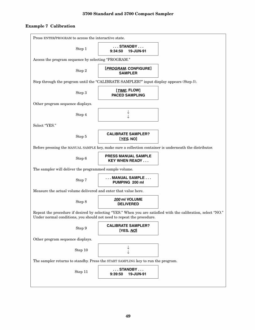
3700 Standard and 3700 Compact Sampler
49
Example 7 Calibration
Press ENTER/PROGRAM to access the interactive state.
Step 1. . . STANDBY . . .
9:34:50 19-JUN-91
Access the program sequence by selecting “PROGRAM.”
Step 2[PROGRAM, CONFIGURE]
SAMPLER
Step through the program until the “CALIBRATE SAMPLER?” input display appears (Step 5).
Step 3[TIME, FLOW]
PACED SAMPLING
Other program sequence displays.
Step 4 ↓↓
Select “YES.”
Step 5CALIBRATE SAMPLER?
[YES, NO]
Before pressing the MANUAL SAMPLE key, make sure a collection container is underneath the distributor.
Step 6 PRESS MANUAL SAMPLEKEY WHEN READY . . .
The sampler will deliver the programmed sample volume.
Step 7 . . . MANUAL SAMPLE . . .PUMPING 200 ml
Measure the actual volume delivered and enter that value here.
Step 8200 ml VOLUME
DELIVERED
Repeat the procedure if desired by selecting “YES.” When you are satisfied with the calibration, select “NO.”Under normal conditions, you should not need to repeat the procedure.
Step 9CALIBRATE SAMPLER?
[YES, NO]
Other program sequence displays.
Step 10 ↓↓
The sampler returns to standby. Press the START SAMPLING key to run the program.
Step 11. . . STANDBY . . .
9:39:50 19-JUN-91
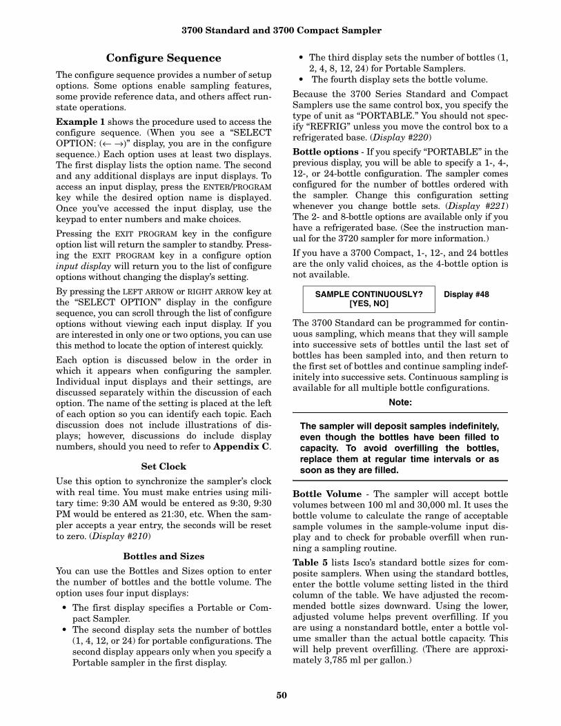
3700 Standard and 3700 Compact Sampler
50
Configure SequenceThe configure sequence provides a number of setupoptions. Some options enable sampling features,some provide reference data, and others affect run-state operations.
Example 1 shows the procedure used to access theconfigure sequence. (When you see a “SELECTOPTION: (← →)” display, you are in the configuresequence.) Each option uses at least two displays.The first display lists the option name. The secondand any additional displays are input displays. Toaccess an input display, press the ENTER/PROGRAMkey while the desired option name is displayed.Once you’ve accessed the input display, use thekeypad to enter numbers and make choices.
Pressing the EXIT PROGRAM key in the configureoption list will return the sampler to standby. Press-ing the EXIT PROGRAM key in a configure optioninput display will return you to the list of configureoptions without changing the display’s setting.
By pressing the LEFT ARROW or RIGHT ARROW key atthe “SELECT OPTION” display in the configuresequence, you can scroll through the list of configureoptions without viewing each input display. If youare interested in only one or two options, you can usethis method to locate the option of interest quickly.
Each option is discussed below in the order inwhich it appears when configuring the sampler.Individual input displays and their settings, arediscussed separately within the discussion of eachoption. The name of the setting is placed at the leftof each option so you can identify each topic. Eachdiscussion does not include illustrations of dis-plays; however, discussions do include displaynumbers, should you need to refer to Appendix C.
Set Clock
Use this option to synchronize the sampler’s clockwith real time. You must make entries using mili-tary time: 9:30 AM would be entered as 9:30, 9:30PM would be entered as 21:30, etc. When the sam-pler accepts a year entry, the seconds will be resetto zero. (Display #210)
Bottles and Sizes
You can use the Bottles and Sizes option to enterthe number of bottles and the bottle volume. Theoption uses four input displays:
• The first display specifies a Portable or Com-pact Sampler.
• The second display sets the number of bottles(1, 4, 12, or 24) for portable configurations. Thesecond display appears only when you specify aPortable sampler in the first display.
• The third display sets the number of bottles (1,2, 4, 8, 12, 24) for Portable Samplers.
• The fourth display sets the bottle volume.
Because the 3700 Series Standard and CompactSamplers use the same control box, you specify thetype of unit as “PORTABLE.” You should not spec-ify “REFRIG” unless you move the control box to arefrigerated base. (Display #220)
Bottle options - If you specify “PORTABLE” in theprevious display, you will be able to specify a 1-, 4-,12-, or 24-bottle configuration. The sampler comesconfigured for the number of bottles ordered withthe sampler. Change this configuration settingwhenever you change bottle sets. (Display #221)The 2- and 8-bottle options are available only if youhave a refrigerated base. (See the instruction man-ual for the 3720 sampler for more information.)
If you have a 3700 Compact, 1-, 12-, and 24 bottlesare the only valid choices, as the 4-bottle option isnot available.
The 3700 Standard can be programmed for contin-uous sampling, which means that they will sampleinto successive sets of bottles until the last set ofbottles has been sampled into, and then return tothe first set of bottles and continue sampling indef-initely into successive sets. Continuous sampling isavailable for all multiple bottle configurations.
Note:
The sampler will deposit samples indefinitely,even though the bottles have been filled tocapacity. To avoid overfilling the bottles,replace them at regular time intervals or assoon as they are filled.
Bottle Volume - The sampler will accept bottlevolumes between 100 ml and 30,000 ml. It uses thebottle volume to calculate the range of acceptablesample volumes in the sample-volume input dis-play and to check for probable overfill when run-ning a sampling routine.
Table 5 lists Isco’s standard bottle sizes for com-posite samplers. When using the standard bottles,enter the bottle volume setting listed in the thirdcolumn of the table. We have adjusted the recom-mended bottle sizes downward. Using the lower,adjusted volume helps prevent overfilling. If youare using a nonstandard bottle, enter a bottle vol-ume smaller than the actual bottle capacity. Thiswill help prevent overfilling. (There are approxi-mately 3,785 ml per gallon.)
SAMPLE CONTINUOUSLY?[YES, NO]
Display #48

3700 Standard and 3700 Compact Sampler
51
Table 5 Bottle Volume Settings for Standard Bottle Configurations
(Note: Under Compatibility, S = 3700 Standard and C = 3700 Compact)
Cumulative Error - The sample accuracy is thegreater of 10% of the sample volume or 20 ml andis repeatable to ± 10 ml. Since samples of 200 mlcan vary by 10% or ± 20 ml, the cumulative errorfor four samples would be ± 80 ml. If the samplerconsistently places an actual sample volume of 220ml for each of the four samples, the total volumeheld by the bottle would be 880 ml. Again, to avoidpossible overfilling, enter a bottle volume that isless than the actual bottle capacity.
Suction Line
You can use the Suction Line configure option toconfigure the sampler for the type (vinyl or Teflon),diameter, and length of the suction line used. Thevolumetric delivery varies with line diameter, type,and length, so it is important that you enter thesesettings accurately. An incorrect setting willimpair the accuracy of the sample volume. Thesesettings can also determine the number of post-sample purge counts. It is important to have suffi-cient counts to completely clear the line.
If you change the current suction line settings, the“. . . CALCULATING . . . PUMP TABLE VALUES”message will appear for a short time. Because thevolumetric delivery of the sample varies with thediameter, type, and length of the suction line; thesampler must revise the internal pump tables. Theelectronic pump count uses the tables as referencefor sample delivery.
There are three types of suction lines available foruse with the 3700 sampler: 1/4-inch vinyl, 3/8-inchvinyl, and 3/8-inch Teflon. If you specify 1/4-inch line,the sampler will prompt you for the line length
immediately. If you specify 3/8-inch line, the samplerprompts you to specify vinyl or Teflon before prompt-ing for the line length. (Display #s 230 and 231)
The sampler will accept suction line lengths of 3 to99 feet. When measuring the line, do not includethe tube coupling or the strainer in the measure-ment. The line should be cut to even foot lengths,such as 6, not 6.5, feet. (Display #232)
Liquid Detector
You can use the Liquid Detector configure option toturn the liquid detector on or off, set the number ofrinse cycles, add a suction-head setting to the pro-gram sequence, and set the number of samplingretries should the suction line become clogged. Theoption uses four input displays. Each display is dis-cussed below.
Enable/Disable Detector - Isco recommends set-ting the Enable/Disable Detector option to“ENABLE.” The 3700 Sampler determines thedelivered-sample volume suction head by countingrevolutions of the peristaltic pump rotor. The vol-ume of liquid delivered by one revolution of thepump rotor is a function of the suction head; as thesuction head increases, the volume delivered byone revolution of the pump rotor decreases.
By enabling the detector, the sampler can accu-rately determine the operating suction head. Itdoes not have to rely on a programmed suction-head value, but can instead begin its volume deliv-ery count when it detects liquid. This minimizesinaccuracies that can occur in changing head con-ditions, or when it is difficult to measure the suc-tion head accurately.
Bottle Configuration Bottle Size Bottle-Volume Setting Compatibility
24 (polypropylene) 1000 ml 1000 S
24 (polyethylene) 500 ml 500 C
24 (glass) 350 ml 350 S
12 (polypropylene, glass) 945 ml 945 S
12 (polypropylene, glass) 300 ml 300 C
4 (glass and polyethylene) 1 gal 3800 S
1 (glass and polyethylene) 2.5 gal 9400 S, C
1 (polyethylene) 4 gal 15,000 S

3700 Standard and 3700 Compact Sampler
52
The disable option is provided should the detector orits associated circuitry become suspect. If you dis-able the detector, the manual suction-head setting(Display #70) is automatically added to the SampleVolume program section in the program sequence. Ifthe detector is disabled, the sampler uses a calcu-lated number of pump counts based on the suction-head entry to deliver the correct sample volume.With the detector disabled, the sampler operates atdiminished accuracy. (Display #240)
Rinse Cycles - The Rinse Cycle setting is avail-able only when the detector is enabled. It sets thenumber of suction-line rinses from 0 to 3. Rinsesare used to condition the suction line to reducecross contamination. During a rinse cycle, thepump draws liquid up through the line until theliquid detector senses it. At that point, the pumpreverses to purge the line. This cycle repeatsaccording to the number of rinse cycles entered(Display #241). Rinse cycles contribute to the wearon pump tubing; therefore, if you use rinse cycles,you may need to replace the tubing more fre-quently. The Tubing Life configure option allowsyou to monitor pump-tubing wear.
Enter Head Manually - When the detector isenabled, you can optionally enter the head manu-ally, allowing you to add the suction-head entry(Display #70) to the program sequence.
When the detector is disabled, the Suction Headentry is automatically added to the programsequence. By disabling the suction-head setting,you allow the liquid detector to determine the oper-ating suction head each time a sample is taken.
When the head is stable and known accurately, youcan further increase the accuracy of the deliveredvolume by using the Suction Head entry in con-junction with the liquid detector. When the head isvariable or unknown, select “NO” because an incor-rect head setting will diminish the delivered vol-ume accuracy. (Display #242)
Sampling Retries - The Sampling Retries optionis available when the detector is enabled. It setsthe number of times (from 0 to 3) the sampler willtry to detect liquid in the line before skipping thesample. You can use this option when sampling liq-uid with a high concentration of solids that tend toclog the suction line or the strainer. The samplerwill also retry the rinse cycle when you are usingthe Sampling Retry option. (Display #243)
Programming Mode
The Programming Mode option allows you to spec-ify either basic or extended programming mode.The basic programming mode is used for conven-tional routines; you can use the extended program-ming mode for either conventional or morecomplex routines. Storm programming is availablethrough the extended programming mode.
Table 6 summarizes the sampling features accord-ing to the programming mode in the programsequence. Table 4, in the section Interactive State,summarizes the features available in the configuresequence. (Display #250)

3700 Standard and 3700 Compact Sampler
53
Table 6 Sampling capabilities through the Program Sequence
Pacing: Mode Feature
Time-Pacing:Uniform Time Intervals
Basic & ExtendedSamples taken at regular time intervals from 1 minute to 99hours, 59 minutes.
Time-Pacing:Nonuniform Clock TimeIntervals
ExtendedSamples taken at irregular time intervals by specifying the timeand date of each sample. You can enter dates as far as one monthin advance of the current date.
Time-Pacing:Nonuniform Intervals inMinutes
ExtendedSamples taken at irregular time intervals by specifying theamount of time in minutes between each sample. You can enterintervals from 1 to 999 minutes.
Flow-Pacing Basic & ExtendedSamples taken at regular flow intervals. The sampler will totalizeflow intervals of 1 to 9,999 pulses.
Distribution:
Sequential Basic & Extended One sample volume placed in each bottle.
Samples-per-Bottle Multiplexing Basic & Extended
More than one sample volume placed in each bottle. You canswitch bottles after a specified number of samples have beendeposited or after a specified time period.
Bottles-per-Sample Multiplexing
Basic & Extended Sample volumes placed in more than one bottle at each sampleevent.
Multiple-BottleCompositing
ExtendedMore than one sample volume placed in a set of bottles. You canswitch bottle sets after a specified number of samples have beendeposited or after a specified time period.
Volumes and Accuracy:
Sample Volume Basic & Extended You can enter volumes from 10 to 9,990 ml.
Suction Head Basic & Extended You can enter suction heads from 1 to 20 feet.
Calibration Basic & Extended You can calibrate sample volumes if desired.
Key Times:
Start Times Basic & ExtendedYou can enter specific start times for both time-paced and flow-paced routines. If you do not enter a start time, Start Time Delayis used.
First Switch Time Extended
Bottles can be switched after specified time intervals. After theroutine starts, the first switch time allows the first bottle or bottleset to receive samples for a partial interval. After the first switch,the remaining sets will receive samples for full time intervals. Thisallows you to place the sampler on schedule.
Stop/Resume Times ExtendedYou can perform intermittent sampling by defining sampling stopand resume times. You can enter as many as 12 stop and 12resume times.
Time-Pacing ExtendedSamples taken at regular time intervals from 1 minute to 99hours, 59 minutes.

3700 Standard and 3700 Compact Sampler
54
Storm Programming (Available through the Extended Mode Only.)
Storm Pacing: Mode Feature
Flow-Pacing ExtendedSamples taken at regular flow intervals. The sampler will totalizeflow intervals of 1 to 9,999 pulses.
Storm Distribution:
Sequential Extended One sample volume placed in each bottle.
Samples-per-Bottle Multiplexing
ExtendedMore than one sample volume placed in each bottle. You canswitch bottles after a specified number of samples have beendeposited.
Bottles-per-Sample Multiplexing Extended
Sample volumes placed in more than one bottle at each sampleevent.
Multiple-Bottle Compositing
ExtendedMore than one sample volume placed in a set of bottles. You canswitch bottle sets after a specified number of samples have beendeposited.
Storm Volumes and Accuracy:
Sample Volume ExtendedEnter volumes from 10 to 990 ml for the time-paced and flow-paced segments separately.
Suction Head Extended You can enter suction heads from 1 to 20 feet.
Calibration Extended Calibrate sample volumes if desired. Sets calibration using thetimed sample volume only.
Storm Key Times:
Delay to First Group Sample
Extended
Enter a time of up to 99 minutes to delay the first sample deliv-ered to the first bottle group. The delay begins after the pro-grammed start time for the STORM routine. In applications wherethere is a flow meter programmed to enable the sampler, the delaybegins after the sampler is enabled.
Delay to Second Group Sample
Extended
A time of up to 99 minutes can be entered to delay the first sampledelivered to the second bottle group, when the second bottle groupreceives time-paced samples. The delay begins after the pro-grammed start time for the STORM routine. In applications wherethere is a flow meter programmed to enable the sampler, the delaybegins after the sampler is enabled.
Start Times ExtendedYou can enter a specific start time for the STORM routine. If nostart time is entered, the Start Time Delay will be used.
Maximum Flow Interval ExtendedYou can enter maximum period of time between flow-paced sampleevents. If this period of time is exceeded, the sampler will termi-nate the routine.
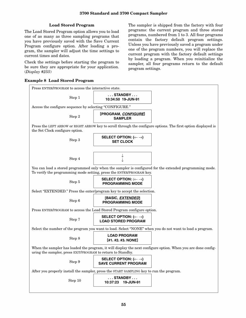
3700 Standard and 3700 Compact Sampler
55
Load Stored Program
The Load Stored Program option allows you to loadone of as many as three sampling programs thatyou have previously saved with the Save CurrentProgram configure option. After loading a pro-gram, the sampler will adjust the time settings tocurrent times and dates.
Check the settings before starting the program tobe sure they are appropriate for your application.(Display #255)
The sampler is shipped from the factory with fourprograms: the current program and three storedprograms, numbered from 1 to 3. All four programscontain the factory default program settings.Unless you have previously saved a program underone of the program numbers, you will replace thecurrent program with the factory default settingsby loading a program. When you reinitialize thesampler, all four programs return to the defaultprogram settings.
Example 8 Load Stored Program
Press ENTER/PROGRAM to access the interactive state.
Step 1. . . STANDBY . . .
10:34:50 19-JUN-91
Access the configure sequence by selecting “CONFIGURE.”
Step 2 [PROGRAM, CONFIGURE]
SAMPLER
Press the LEFT ARROW or RIGHT ARROW key to scroll through the configure options. The first option displayed isthe Set Clock configure option.
Step 3SELECT OPTION: (← →)
SET CLOCK
Step 4↓↓
You can load a stored programmed only when the sampler is configured for the extended programming mode.To verify the programming mode setting, press the ENTER/PROGRAM key.
Step 5 SELECT OPTION: (← →)PROGRAMMING MODE
Select “EXTENDED.” Press the enter/program key to accept the selection.
Step 6[BASIC, EXTENDED]
PROGRAMMING MODE
Press ENTER/PROGRAM to access the Load Stored Program configure option.
Step 7SELECT OPTION: (← →)
LOAD STORED PROGRAM
Select the number of the program you want to load. Select “NONE” when you do not want to load a program.
Step 8LOAD PROGRAM[#1, #2, #3, NONE]
When the sampler has loaded the program, it will display the next configure option. When you are done config-uring the sampler, press EXIT/PROGRAM to return to Standby.
Step 9SELECT OPTION: (← →)
SAVE CURRENT PROGRAM
After you properly install the sampler, press the START SAMPLING key to run the program.
Step 10. . . STANDBY . . .
10:37:23 19-JUN-91
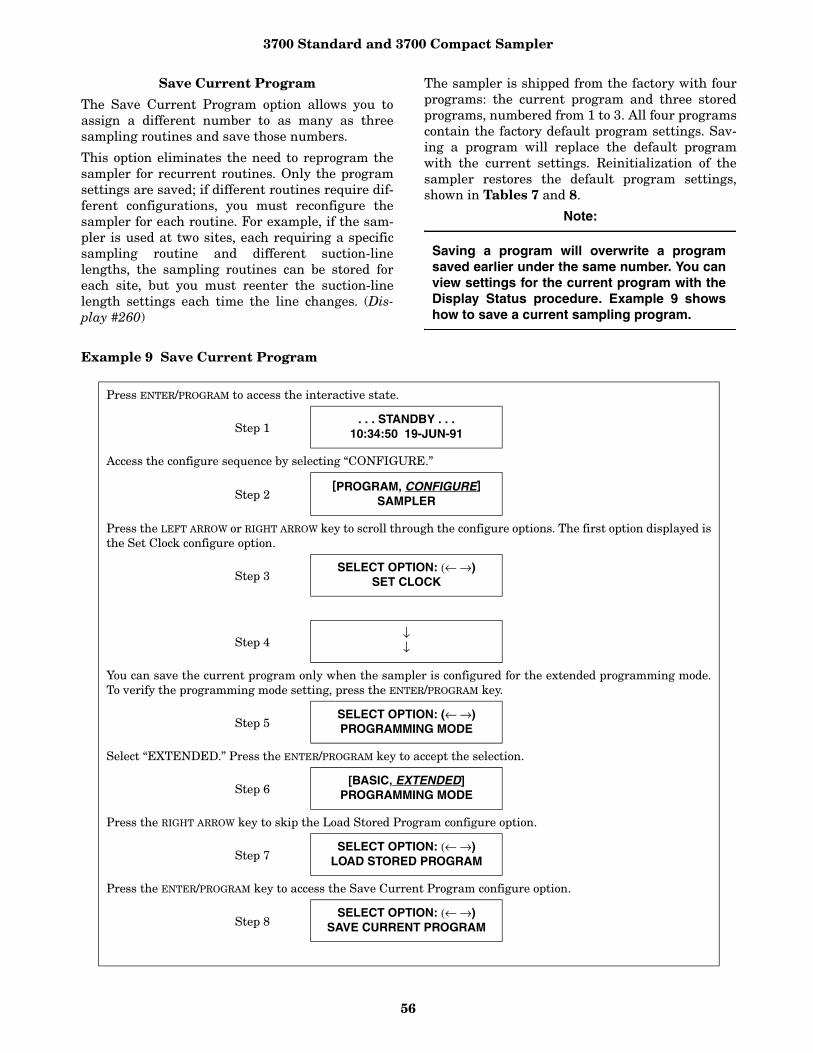
3700 Standard and 3700 Compact Sampler
56
Save Current Program
The Save Current Program option allows you toassign a different number to as many as threesampling routines and save those numbers.
This option eliminates the need to reprogram thesampler for recurrent routines. Only the programsettings are saved; if different routines require dif-ferent configurations, you must reconfigure thesampler for each routine. For example, if the sam-pler is used at two sites, each requiring a specificsampling routine and different suction-linelengths, the sampling routines can be stored foreach site, but you must reenter the suction-linelength settings each time the line changes. (Dis-play #260)
The sampler is shipped from the factory with fourprograms: the current program and three storedprograms, numbered from 1 to 3. All four programscontain the factory default program settings. Sav-ing a program will replace the default programwith the current settings. Reinitialization of thesampler restores the default program settings,shown in Tables 7 and 8.
Note:
Saving a program will overwrite a programsaved earlier under the same number. You canview settings for the current program with theDisplay Status procedure. Example 9 showshow to save a current sampling program.
Example 9 Save Current Program
Press ENTER/PROGRAM to access the interactive state.
Step 1. . . STANDBY . . .
10:34:50 19-JUN-91
Access the configure sequence by selecting “CONFIGURE.”
Step 2[PROGRAM, CONFIGURE]
SAMPLER
Press the LEFT ARROW or RIGHT ARROW key to scroll through the configure options. The first option displayed isthe Set Clock configure option.
Step 3SELECT OPTION: (← →)
SET CLOCK
Step 4↓↓
You can save the current program only when the sampler is configured for the extended programming mode.To verify the programming mode setting, press the ENTER/PROGRAM key.
Step 5SELECT OPTION: (← →)PROGRAMMING MODE
Select “EXTENDED.” Press the ENTER/PROGRAM key to accept the selection.
Step 6[BASIC, EXTENDED]
PROGRAMMING MODE
Press the RIGHT ARROW key to skip the Load Stored Program configure option.
Step 7SELECT OPTION: (← →)
LOAD STORED PROGRAM
Press the ENTER/PROGRAM key to access the Save Current Program configure option.
Step 8SELECT OPTION: (← →)
SAVE CURRENT PROGRAM

3700 Standard and 3700 Compact Sampler
57
Flow-Mode Sampling
The Flow-Mode Sampling option directs the sam-pler to take a sample at key times in a flow-pacedsampling program. There are two settings. Thefirst setting directs the sampler to take a sample atthe start time. The second directs the sampler totake a sample at the switch times (when the bottleset changes are based on time).
Sample at Start Time - If you select “YES,” the3700 will take the first sample at the start timeentered in the program sequence. If you select“NO,” the first sample is delayed until the numberof flow pulses, set in the program sequence, hascounted down to zero. (Display #270)
Sample at Time Switch - If you select “YES,” thesampler will switch to a new bottle or set, take asample, and reset the flow pulse count. The nextsample will occur after a full pulse countdown. Ifyou select “NO,” no samples be taken at the switchtime and the pulse countdown will not be reset.The switch will occur in the middle of a pulsecountdown and the first sample will be depositedin the new bottle or set when the countdown iscompleted. (Display #271)
Nonuniform Time
The Nonuniform Time option specifies the methodby which nonuniform intervals are to be entered inthe extended program sequence (Display #s 26 or27). If you select “clock-time,” you will be able toenter a specific time and date for each sampleevent when entering settings in the programsequence. If you select “MINUTES,” you will beable to enter nonuniform intervals in minutes.Nonuniform times are not available in a STORMsampling routine. (Display #280)
Calibrate Sampler
The Calibrate Sampler option adds or removes thecalibration settings to the program sequence. If
you select “ENABLE,” the calibration displays willbe added to the program sequence and you will beable to precisely calibrate the sample volumes.(Display #290)
Sampling Stop/Resume
The Sampling Stop/Resume configure option letsyou add stop and resume settings (Display #s 100,101, and 102) to the program sequence.
The Stop/Resume settings appear in the key timesection of the program sequence. (You can enter asmany as 24 times: 12 stop times and 12 resumetimes.) For example, the Stop/Resume optionallows you to define a sampling routine, which willtake samples at intervals of 15 minutes between 6AM to 8 AM and between 4 PM to 6 PM. SamplingStops and Resumes are not available in a stormroutine.
If you are using a time-switched sampling routinethat includes the use of stops and resumes, thesampler will reset the time-switch interval at eachresume time. If a routine with time-switches everyhour is programmed for stop and resume times, thefirst time-switch would occur an hour after theresume time.
Switches would repeat every hour until a stop timeoccurred or the routine was completed. See Exam-ple 16.
Enable/Disable - Select “ENABLE” to add thestops and resume settings to the programsequence. (Display #300)
Sample at Stop - The Sample at Stop settingdirects the sampler to take a sample at stop times.(Display #301)
Sample at Resume - The Sample at Resume set-ting directs the sampler to take a sample atresume times. (Display #302)
Select the number you want to use as the program “name.” Select “NONE” when you do not want to save aprogram When the sampler has saved the program, it will display the next configure option. When you aredone configuring the sampler, press EXIT/PROGRAM to return to Standby.
Step 9SAVE PROGRAM AS
[#1, #2, #3, NONE]
When the sampler is properly installed, press the START SAMPLING key to run the program.
Step 10. . . STANDBY . . .
10:37:23 19-JUN-91
3700 Standard and 3700 Compact Sampler
58
Start Time Delay
The Start Time Delay option sets the amount oftime in minutes, between the time you press thestart sampling key and the time the sampling rou-tine is initiated. The sampler’s response variesaccording to specific entries: 0, 1, and entriesgreater than 1.
An entry of 0 eliminates the delay to start time;the start time occurs the moment you press startsampling. For example, if you press start samplingat 10:32:15, the sampler will initiate a time-pacedsample event at 10:32:15.
The sampler will start clocking time intervals atthe beginning of the minute (HH:MM:00) of thefirst sample event. If a sampling routine required10-minute intervals and you pressed start sam-pling at 10:32:15, the sampler would begin thetime interval at 10:32:00. It would initiate the sec-ond sample event at 10:42:00. The sampler wouldbegin the flow interval at 10:32:15 for flow-pacedroutines.
If you entered a start-time delay of 1, the samplerwould begin the routine at the beginning of thenext minute. Thus, if you pressed start sampling at10:32:15, the sampler would initiate the sampleevent at 10:33:00. The sampler would begin timeand flow intervals at 10:33:00. If you enter a start-time delay of 2, the sampler would begin time orflow intervals at 10:34:00. (Display #310)
Note:
If you enter a start time, the sampler will dis-regard the start-time delay. The sampler willuse the start-time delay setting when you donot enter the start time in the programsequence. When using a start time delay ofgreater than 0, take care when the sampler isbeing inhibited by another sampler, a flowmeter, or a Liquid Level Actuator.
Enable Pin
The Enable Pin option allows you to program thesampler’s response to a device controlling pin F ofthe flow meter connector, for example, a 3200 or4200 Series Flow Meter, a 4100 Series Flow Logger,or the Model 1640 Liquid Level Actuator. There arefour Enable Pin setup options: Sample Upon Dis-able, Sample Upon Enable, Reset Sample Interval,and Inhibit Countdown. The sampler disregards
the Enable Pin configure option settings when run-ning a storm routine. Each of these options is dis-cussed below.
Sample Upon Disable - When you are using aflow meter or Liquid Level Actuator, “SAMPLEUPON DISABLE?” allows you to direct the sam-pler to take a sample as soon as you disable thesampler through pin F.
A response of “YES” causes the sampler to take asample when the pin is disabled; a response of“NO” prevents the sampler from taking a sample.(Display #321)
The sampler determines an enable or disable con-dition by monitoring the voltage on pin F. It inter-prets high voltage as an enable signal and lowvoltage or ground as a disable signal.
Sample Upon Enable - When you are using aflow meter or Liquid Level Actuator, “SAMPLEUPON ENABLE?” allows you to direct the samplerto take a sample as soon as the sampler is enabledthrough pin F. A response of “YES” causes the sam-pler to take a sample when the pin is enabled. Aresponse of “NO” prevents the sampler from takinga sample when the pin is enabled. (Display #322)
Reset Sample Interval - “Reset Sample Inter-val?” controls the time- or flow-pulse countdown. Ifyou select “YES,” a full sample interval beginswhen pin F is enabled. If you select “NO,” theinterval will not be reset when the sampler isenabled; the settings entered in the “INHIBITCOUNTDOWN?” option will be used. If you aresampling on a time-paced basis and wish to syn-chronize all sampling with real time, do not resetthe sample interval. (Display #323)
Inhibit Countdown - “INHIBIT COUNT-DOWN?” is only applicable when you respond“NO” to “RESET SAMPLE INTERVAL?” TheInhibit Countdown option controls the countdownwhile the sampler is disabled. Select “YES” tofreeze the countdown to the next sample. Thecount will resume when the sampler is enabled.Select “NO” to allow the countdown to continuewhile the sampler is disabled. (Display #324)
A sampler that has been inhibited while running aroutine will move to the next bottle set whenenabled, if at least one sample volume has beendeposited in the current bottle set. This is true forboth time-switched and count-switched routines,and for bottles sets composed of one or more bottles.
A sampler that has been inhibited while running atime-switched routine will advance to the next bot-tle or bottle set, regardless of the number of time-switches that elapse while the sampler is inhibited.
---- MINUTE DELAY TO START (0 - 9999)
Display #310

3700 Standard and 3700 Compact Sampler
59
If the bottle sets were switched every two hoursand the sampler has been inhibited for six hours,the restarted routine will begin with the next bot-tle set. The routine may not continue with the bot-tle set that would have been used had the samplernot been inhibited.
Event Mark
The Event Mark option configures the sampler tosend an event mark to an interfaced flow meter orother equipment. The sampler will supply a vari-able duration pulse of up to 700 mA at 12 V on pinE of the flow meter connector. Four types of signalscan be sent:
• a pulse at the beginning of the pre-sample purge;• a pulse at the beginning of forward pumping
only;• a continuous signal during the entire pump cycle;• a continuous signal during forward pumping
only.
The event mark includes a signal sent on pin Dwhich is interpreted and recorded by Isco’s 3200and 4200 Series Flow Meters, and 4100 SeriesFlow Loggers as the bottle number(s) for the sam-ple event.
The bottle number signal consists of a number of100 millisecond, 12-volt pulses that equal the bot-tle number; i.e., four pulses represent bottle #4, 20pulses represent bottle #20.
The type of signal selected from the Event Markconfigure option affects the event mark signal onpin E. In Figure 16A, a pulse signal is sent at thebeginning of the pre-sample purge. In Figure 16B,a pulse signal is sent during the sample volumedelivery portion of the sample event. In Figure16C, a continuous signal is sent during the entirepump cycle. In Figure 16D, a continuous pulse issent for the duration of the sample-volume delivery.
Continuous/Pulse Signal - The Continuous/Pulsesetting selects either continuous or pulse signals.Pulse signals are three seconds in duration; continu-ous signals are three seconds or longer and dependon the setting and the pump cycle. (Display #330)
Continuous Signal Timing - The Pump Cycle/Fwd Pumping settings will appear when you haveselected “CONTINUOUS SIGNAL.” Select “PUMPCYCLE” when you want a continuous signal trans-mitted during the entire pump cycle, from thebeginning of the pre-sample purge to the end of thepost-sample purge. Select “FWD PUMPING” whenyou want a continuous signal transmitted while thepump is delivering a sample volume. (Display #331)
Pulse Signal - The Pulse Signal setting willappear when you select “PULSE.” Two options areavailable. The first option, “PURGE,” sends a pulseat the beginning of the pre-sample purge. The sec-ond option, “FWD PUMPING,” sends a pulse at thebeginning of the sample delivery when the pump isrunning forward. (Display #332)
Purge Counts
The Purge Counts option is used to override thenumber of pump counts needed to clear the suctionline in both pre-sample purge and post-samplepurge cycles.
The pre-sample purge count is normally set to 150counts and will be reset to this value if the sampleris reinitialized. The post-sample purge count isderived from the suction line diameter and lengthsettings. If your observations indicate that agreater or lesser number of pump counts in eitherpurge is needed, you can change the count settings.Entries are to be between 0 and 9,999 for bothpurges. You can obtain a purge count using thepump forward or pump reverse keys. (Display #s340 and 341)
Tubing Life
The Tubing Life option sets the number of pumpcounts needed to trigger the “Replace Pump Tub-ing” warning. The warning is activated when thepump count reaches the entered value. You mustreset the pump counter after replacing the pumptubing. If you consistently experience a tubing fail-ure at a pump count that differs significantly fromthe current setting, enter that value here. The fac-tory-set value of 500,000 pump counts will deliverapproximately 500 samples of 200 ml each, using a3/8-inch-by-10-foot vinyl suction line at a 5-foot suc-tion head. (Display #350, 351, and 352)
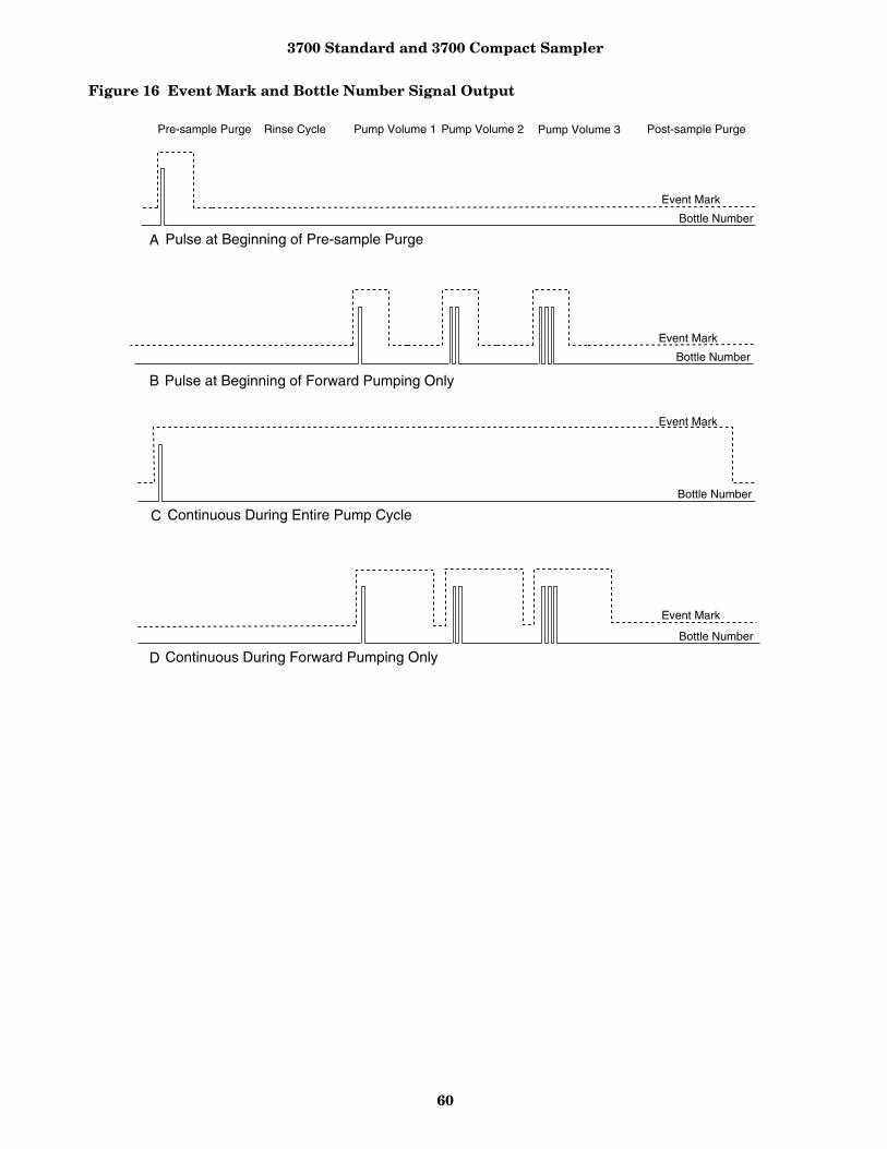
3700 Standard and 3700 Compact Sampler
60
Figure 16 Event Mark and Bottle Number Signal Output
Pre-sample Purge Rinse Cycle Pump Volume 1 Pump Volume 2 Pump Volume 3 Post-sample Purge
Event Mark
Event Mark
Bottle Number
Event Mark
Bottle Number
Event Mark
Bottle Number
Bottle Number
A
B
C
D
Pulse at Beginning of Pre-sample Purge
Pulse at Beginning of Forward Pumping Only
Continuous During Entire Pump Cycle
Continuous During Forward Pumping Only

3700 Standard and 3700 Compact Sampler
61
Program Lock
Select “ENABLE” to turn the lock on. When theProgram Lock is enabled, each protected displaycan be viewed, but no values can be changed with-out first entering the pass-number: 3700. Once thepass-number has been entered, you can changeany value or setting in either the program or con-figure sequence. (Display #360)
Sampler ID
The Sampler ID option allows you to enter a 10character identification number (ID) for the sam-pler. The ID number is used to identify samplingreports produced by the Isco Field Printer and infiles created by SAMPLINK. The sampler isshipped from the factory with 10 dashes (-) enteredfor the ID. (Display #365)
Acceptable Characters - The ID field will acceptdigits, dashes, spaces, and periods. You can enterspaces, dashes, and periods with three of the con-trol keys. Enter a space with the START SAMPLINGkey, a dash (-) with the MANUAL SAMPLE key, and aperiod with the RESUME SAMPLING key.
Run Diagnostics
Run Diagnostics performs a number of diagnosticfunctions. This option contains the software revi-sion number; tests the sampler’s RAM (RandomAccess Memory), ROM (Read Only Memory), dis-play, distributor, and pump; and lets you reinitial-ize RAM. The display information is discussedbelow in order of appearance.
Software Revision Number - The sampler willdisplay the software revision number for a shortperiod of time.
Test RAM and ROM - RAM and ROM test mes-sages replaced the software revision display. A suc-cessful test is indicated by the messages “RAMPASSED TEST” or “ROM PASSED TEST.” If eitherRAM or ROM fail the test, the sampler displaysone of the following messages: “RAM FAILEDTEST” or “ROM FAILED TEST” and beeps everythree seconds until you turn it off. If either theRAM or ROM fail the test, service the sampler.Contact Isco Customer Service for assistance.
LCD Test - After successful RAM and ROM tests,the sampler will then test the LCD by first fillingthe display with solid rectangles and then printingthe alphabet and other characters. Each characterposition in the display should contain a character.
Pump Test - The next step tests the pump. Duringthe test, the pump will run briefly and the displaywill indicate an “OFF/ON” number. The numbershould fall within the range of 50 to 200. If thecount falls below 50 or exceeds 200, have the pumpserviced. A count near 100 is typical.
Distributor Test - Following the pump test, youcan test the distributor. If you elect to test the dis-tributor, the sampler will move the distributor toPosition 24, then return it to Position 1.
The positions are indicated on the display. If themessage, “DISTRIBUTOR JAMMED” is displayed,check the routing of the pump tubing and the bot-tles in the tub. If the tubing and bottles are cor-rectly positioned, the distributor drive mechanismmay need servicing. (Display #370)
Reinitialize Controller - In the final steps youreinitialize the sampler. If you select “NO,” thesampler will return to the configure option list. Ifyou select “YES,” the sampler will reset a numberof configuration and program settings, then youcan turn off the sampler. (Display #371)
Table 7 lists the reinitialized settings. Note: Notall settings are reset. Set Clock, Bottle Size, Suc-tion Line, and Sampler ID configure-option set-tings remain unchanged. This reduces the numberof settings you would need to change if the samplerwere accidently reinitialized. The Pump Counttotal is not reset to maintain an accurate count forthe Tubing Life Warning.
Exit Configuration
This option allows you to leave the configuresequence and return to the standby state. Thereare no input displays. Press the enter/program keyto exit the configure sequence. You can exit theconfiguration sequence at any time using the EXITPROGRAM key.

3700 Standard and 3700 Compact Sampler
62
Table 7 Factory Configure Option settings
CONFIGURE OPTION DISPLAY NO. FACTORY SETTING
SET CLOCK 210 Not Reset
BOTTLES AND SIZE 220, 221, 222, 223 Not Reset
SUCTION LINE 230, 231, 232 Not Reset
LIQUID DETECTOR
liquid detector 240 ENABLE
rinses 241 0
enter head manually 242 NO
# of retries 243 0
PROGRAMMING MODE 250 BASIC
LOAD STORED PROGRAM 255
SAVE CURRENT PROGRAM 260
FLOW MODE SAMPLING
sample at start time 270 NO
sample at switch times 271 NO
NONUNIFORM TIME 280 MINUTES
CALIBRATE SAMPLER 290 DISABLE
SAMPLING STOP/RESUME 300 DISABLE
sample at stop times 301 NO
sample at resume times 302 NO
START TIME DELAY 310 2
ENABLE PIN
master /slave 320 DISABLE
sample upon disable 321 NO
sample upon enable 322 NO
reset sample interval 323 NO
inhibit countdown 324 NO
EVENT MARK
continuous /pulse 330 CONTINUOUS SIGNAL
pump cycle/fwd only 331 FWD PUMPING ONLY
purge/fwd pumping 332 FWD PUMPING
PURGE COUNTS
pre-sample counts 340 150
post-sample counts 341 BASED ON LINE LENGTH
TUBING LIFE
reset pump counter 351 NO
# pump counts 352 Not reset
PROGRAM LOCK 360 DISABLE
SAMPLER ID 365 Not reset
RUN DIAGNOSTICS

3700 Standard and 3700 Compact Sampler
63
Table 8 Factory Program settings
PROGRAM SETTING DISPLAY NO. FACTORY SETTING
[TIME, FLOW] PACED SAMPLING
10 TIME
UNIFORM/ NONUNIFORM TIME INTERVALS
11 UNIFORM
[TIME, FLOW, STORM]PACED SAMPLING
12 TIME
[TIME, FLOW]BOTTLE GROUP
14 FLOW
-- MINUTE DELAY TO FIRST TIMED SAMPLE
15 0 MINUTES
[DURING, AFTER] TIME MODE
16 DURING
_MINUTE DELAY TOSECOND GROUP SAMPLES
17 30
SAMPLE EVERY -- HOURS -- MINUTES
21 1 HOUR 0 MINUTES
SAMPLE EVERY -- PULSES (1 - 9999) 22 10
TAKE -- TIMED SAMPLE EVENTS (1-MAX)
23 1
SAMPLE INTERVALS OF --MINUTES (1-99)
24 60
TAKE --- SAMPLES (1 - MAX) 25 10
QUANTITY AT INTERVAL 1. -- AT -- MINUTES
27 1 AT 60 MINUTES
-- BOTTLES PER SAMPLE EVENT (1 - 24) 30 1
-- SAMPLES PER BOTTLE (1-MAX)
31 1
MULTIPLEX SAMPLES? [YES, NO]
35 NO
[BOTTLES/SAMPLE, SAMPLES PER BOTTLE]
36 SAMPLES PER BOTTLE
CHANGE BOTTLES BASED ON [TIME, SAMPLE]
40 COUNT
CHANGE SETS BASED ON [TIME, SAMPLE]
41 COUNT

3700 Standard and 3700 Compact Sampler
64
Extended Programming Mode
All sampling capabilities available in the basic pro-gramming mode are available in the extended pro-gramming mode. (A listing of the capabilities is inTable 6.) The extended programming mode pro-vides several additional capabilities: NonuniformTime Pacing, an additional multiplexing scheme(multiple-bottle compositing), Sampling Stops andResumes, program storage, and Flow-Mode Sam-pling controls.
The procedure for programming the sampler in theextended mode is the same as that used to pro-gram the sampler in the basic programming mode.There are some exceptions, however. The extendedmode modifies the sections of the programsequence to allow you to take advantage of theadditional features. The Sample Pacing program
section is extended to include settings for nonuni-form times. The Sample Distribution section ismodified to let you program the sampler for multi-ple-bottle compositing. The procedure and displaysused to program the sampler for bottles-per-sam-ple and samples-per-bottle multiplexing, andsequential sampling are somewhat different. Thesection is also extended to allow you to switch mul-tiplexed bottles or bottle sets after programmedperiods of time. (With the extended mode, you canstill switch bottles after a programmed number ofsamples have been deposited.) The Key Times sec-tion is extended to allow you to enter the time ofthe first bottle or bottle set change. If you haveenabled the Sampling Stops and Resumes config-ure option, the Key Times section is extended toincluded displays for sampling stops and resumes.
PROGRAM SETTING DISPLAY NO. FACTORY SETTING
CHANGE BOTTLES EVERY --HOURS, -- MIN.
42 2 HOURS 0 MINUTES
CHANGE SETS AFTER -- HOURS -- MINUTES
43 2 HOURS 0 MINUTES
CHANGE BOTTLES AFTER -- SAMPLES
44 1
CHANGE SETS AFTER SAMPLES
45 1
SAMPLE CONTINUOUSLY?[YES, NO]
48 NO
SAMPLE VOLUMES OF --- ml EACH (10 - MAX)
50 200
--- COMPOSITE SAMPLES (0 - MAX) 60 10
SUCTION HEAD OF -- FEET (1 - MAX) 70 10
ENTER START TIME? [YES, NO] 90 NO
STORM ENABLED AFTER HH:MM MM/DD
93
ENTER FIRST SWITCH TIME? [YES, NO]
95 NO
-- STOP or RESUME TIMES (0 - 24)
100 0
MAX FLOW INTERVAL OF -- HOURS, --MINUTES
110 2 HOURS 0 MINUTES
3700 Standard and 3700 Compact Sampler
65
Each of these extended features is discussedbriefly below. You may find it helpful to refer toFigures 17, 18, and 19, which chart the programsequence in the extended mode.
Extended Mode Sample Pacing
In the extended programming mode, the SamplePacing section allows you to select flow pacing, orone of two types of time-pacing: uniform or nonuni-form. If you select uniform time intervals, the set-tings for time intervals are identical to the timeintervals entered in the basic programming mode.
Nonuniform times allow you to pace the sampler atirregular intervals. Before you enter nonuniformtime intervals, you must specify either minutes orclock times in the Nonuniform Times configureoption. You can enter nonuniform intervals in twoways. The first method allows you to define theinterval between each sample event in minutes.For example, you can program the sampler to takesample #2 after an interval of 10 minutes, sample#3 after an interval of 30 minutes, sample #4 afteran interval of 60 minutes, and so on. Sample #1would be taken at the start time. The secondmethod allows you to enter a specific time and datefor each sample event. For example, with nonuni-form time pacing, you can collect samples at spe-cific times and dates at irregular intervals: 6 AMon April 15, noon on April 15, 7 AM on April 16,and 1 PM on April 16.
If you have several sequences of nonuniform times,you can use the program storage feature to savethe programs using each sequence.
Extended Mode Sample Distribution
The extended Sample Distribution section expandsthe multiplexing capabilities of the sampler. Boththe bottles-per-sample and samples-per-bottle mul-tiplexing are available; however, the procedureused to program them differs slightly from the pro-cedure used in the basic programming mode.Example 11 demonstrates the procedure used forsamples-per-bottle multiplexing; Example 12shows the bottles-per-sample multiplexing proce-dure. The extended mode also offers multiple bot-tle compositing; refer to Example 13.
In the extended programming mode, you canswitch bottles or bottle sets after a programmedtime period elapses or after a programmed numberof samples have been deposited. The displays usedto specify the type of switches are shown in theSample Distribution section of Figures 17, 18,and 19. Display #40 allows you to select either“TIME” or “SAMPLES.” If you select “TIME,” the
bottles can be changed after a programmed periodof time. If you select “SAMPLES,” the bottles canbe switched after a programmed number of sam-ples. In Display #41, which allows you to switchbottle sets, you can select either “TIME” or “SAM-PLES/BTL.” If you select “TIME,” the bottle setscan be changed after a programmed period of time.If you select “SAMPLES/BTL,” the bottle sets canbe changed after a programmed number of sam-ples. You can use select either “TIME,” “SAM-PLES,” or “SAMPLE/BTL” settings with both time-and flow-paced sampling.
Extended Mode Sample Volumes
The extended mode Sample Volumes section isidentical to the basic Sample Volume section.
Extended Mode Key Times
The extended mode Key Times section has twoadditional sets of displays which allow you to spec-ify the time of the first bottle or bottle set changeand to set up the sampling stop and resume times.
First Switch Time - The first switch time dis-plays will appear only when you have specified bot-tle or bottle set changes based on time in theSample Distribution section. If you select “TIME”rather than “SAMPLES” in the “CHANGE SETSBASED ON [TIME, SAMPLES]” display, you firstwill be asked if you want to enter a setting for thefirst switch time. If you respond “YES,” you will beprompted for the time of the first bottle or setchange. The first time-switch displays are indi-cated by Display #s 95, 46, and 47 in Figure 18.
The first switch- time setting allows you to controlthe times of each bottle switch without delayingthe routine and thereby missing samples. Forexample, if you have programmed the sampler fortime switches every hour and you want theswitches to occur on the hour, you can set the timeof the first switch at the next even hour, start thesampling routine early, and deposit samples in thefirst bottle set until the first switch time. At thefirst switch time, the distributor moves to the nextbottle set. The first bottle set may not be com-pletely filled; however, by starting the routineearly, you can sample until the bottle switches areplaced “on schedule” to avoid missing any samples.If you do not enter a first switch time, the samplerwill begin timing the switch interval from the starttime for the routine and the first bottle or bottleset will receive samples for the full time period.Switch times are not available in STORM routines.
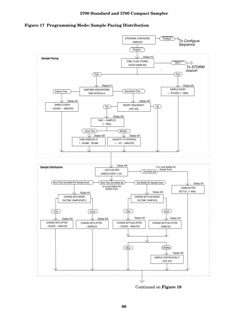
3700 Standard and 3700 Compact Sampler
66
Figure 17 Programming Mode: Sample Pacing Distribution
MinutesClock-Time
Time
[UNIFORM, NONUNIFORM]
TIME INTERVALSUniform Time
SAMPLE EVERY
-- HOURS -- MINUTESMODIFY SEQUENCE?
[YES, NO]
Nonuniform Time
TAKE --- SAMPLES
(1 - MAX)
QUANTITY AT INTERVAL
1. -- AT --- MINUTES
TAKE SAMPLES AT
1. HH:MM DD-MM
Flow
SAMPLE EVERY
---- PULSES (1 - 9999)
Yes No
Display #11 Display #22
Display #20
Display #27
Display #25
Display #26
Display #21
Sample Pacing
[PROGRAM, CONFIGURE]
SAMPLER
[TIME, FLOW, STORM ]
PACED SAMPLING
Display #12
Program
Configure
Storm
To ConfigureSequence
Display #30
Display #44
-- BOTTLES PER
SAMPLE EVENT (1-24)
CHANGE SETS BASED
ON [TIME, SAMPLES/BTL]
CHANGE BOTTLES BASED
ON [TIME, SAMPLES]
One Botttle Per Sample Event
CHANGE SETS AFTER
-- HOURS -- MINUTESCHANGE SETS AFTER
-- SAMPLES
CHANGE BOTTLES AFTER
-- HOURS -- MINUTESCHANGE BOTTLES AFTER
-- SAMPLES
Time Count Time Count
More Than One Bottle Per Sample Event
Display #40
Display #45 Display #42Display #43
Display #41
More Than One Bottle Set
One Bottle Set
13 or more Bottles PerSample Event
12 or less Bottles PerSample Event
Sample Distribution
-- SAMPLES PER
BOTTLE (1- MAX)
Display #31
SAMPLE CONTINUOUSLY?
[YES, NO]
Display #48
Other 2 Bottles
To STORMbranch
Continued on Figure 18
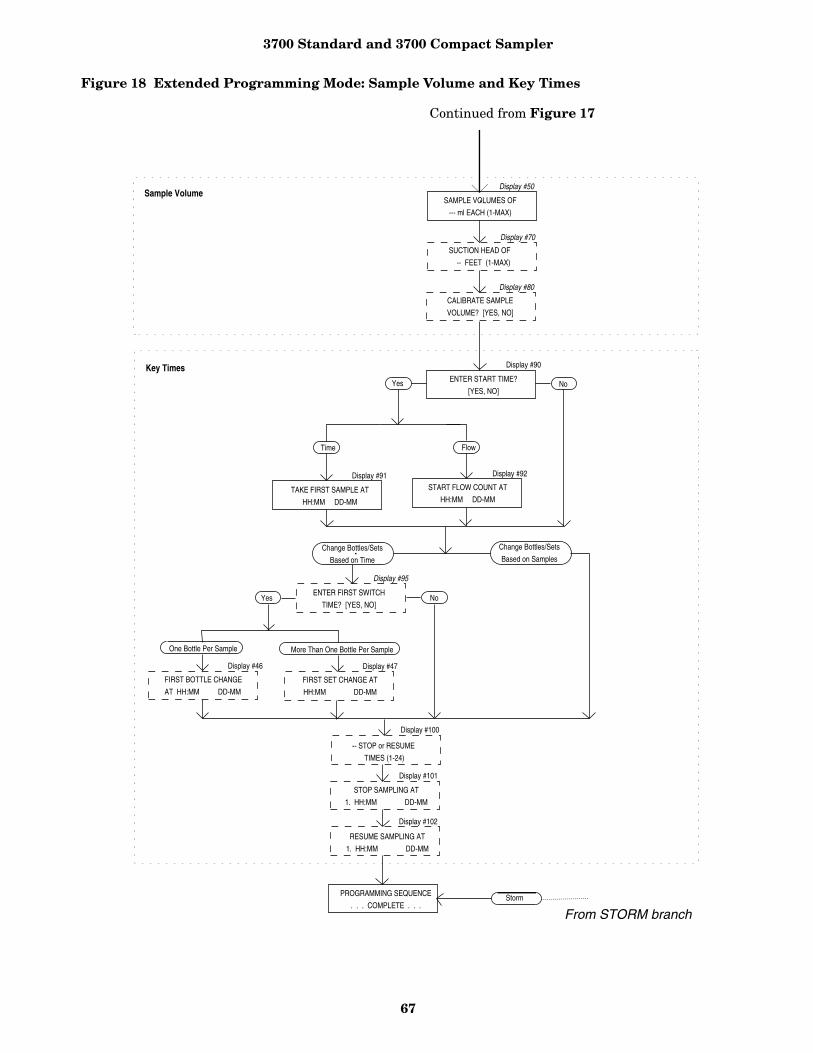
3700 Standard and 3700 Compact Sampler
67
Figure 18 Extended Programming Mode: Sample Volume and Key Times
ENTER START TIME?
[YES, NO]
Display #90
FIRST SET CHANGE AT
HH:MM DD-MM
-- STOP or RESUME
TIMES (1-24)
RESUME SAMPLING AT
1. HH:MM DD-MM
STOP SAMPLING AT
1. HH:MM DD-MM
More Than One Bottle Per SampleOne Bottle Per Sample
Display #46
Display #100
Display #101
Display #102
Display #47
FIRST BOTTLE CHANGE
AT HH:MM DD-MM
FlowTime
TAKE FIRST SAMPLE AT
HH:MM DD-MM
START FLOW COUNT AT
HH:MM DD-MM
Display #91 Display #92
No
PROGRAMMING SEQUENCE
. . . COMPLETE . . .
Change Bottles/Sets
Based on Time
Change Bottles/Sets
Based on Samples
ENTER FIRST SWITCH
TIME? [YES, NO]Yes No
Display #95
SUCTION HEAD OF
-- FEET (1-MAX)
CALIBRATE SAMPLE
VOLUME? [YES, NO]
SAMPLE VOLUMES OF
--- ml EACH (1-MAX)
Display #50
Display #70
Display #80
Yes
Sample Volume
Key Times
Storm
From STORM branch
Continued from Figure 17

3700 Standard and 3700 Compact Sampler
68
Figure 19 Extended Programming Mode: STORM Programming
Display #15
Display #23
Display #24
Display #30
Display #31
Display #50
Display #30
Display #31
--- MINUTE DELAY TO
FIRST GROUP SAMPLE
TAKE -- TIMED
SAMPLE EVENTS (1 - MAX)
SAMPLE INTERVALS OF
-- MINUTES (1 - 999)
__ BOTTLES PER
SAMPLE EVENT (1 - MAX)
__ SAMPLES PER
BOTTLE (1 - MAX)
SAMPLE VOLUMES OF
--- ml EACH (10 - MAX)
-- BOTTLES PER
SAMPLE EVENT (1 - MAX)
-- SAMPLES PER
BOTTLE (1 - MAX)
TIME MODE
FIRST BOTTLE GROUP
Display #50
SAMPLE VOLUMES OF
____ ml EACH (10 - MAX)
SUCTION HEAD OF
-- FEET (1-MAX)
CALIBRATE SAMPLE
VOLUME? [YES, NO]
Display #70
Display #80
ENTER START TIME?
[YES, NO]
Display #90
STORM ENABLED AFTER
HH:MM DD-MMM
Display #93
Display #17
Display #24
__ MINUTE DELAY TO
SECOND GROUP SAMPLES
SAMPLE INTERVAL OF
___ MINUTE (1 - 9999)
Display #16
Display #22
[DURING, AFTER]
FIRST GROUP
SAMPLE EVERY
---- PULSES (1 - 9999)
MAX FLOW INTERVAL OF
-- HOURS -- MINUTES
Display #110
Time Flow
PROGRAMMING SEQUENCE
. . . COMPLETE . . .
[PROGRAM, CONFIGURE]
SAMPLER
[TIME, FLOW, STORM ]
PACED SAMPLING
Display #12
Program
Configure
Storm
First Bottle Group
Second Bottle Group
STORM Key Times
[TIME, FLOW]
SECOND BOTTLE GROUP
Display #14
-- BOTTLES, -----ml
AVAILABLE
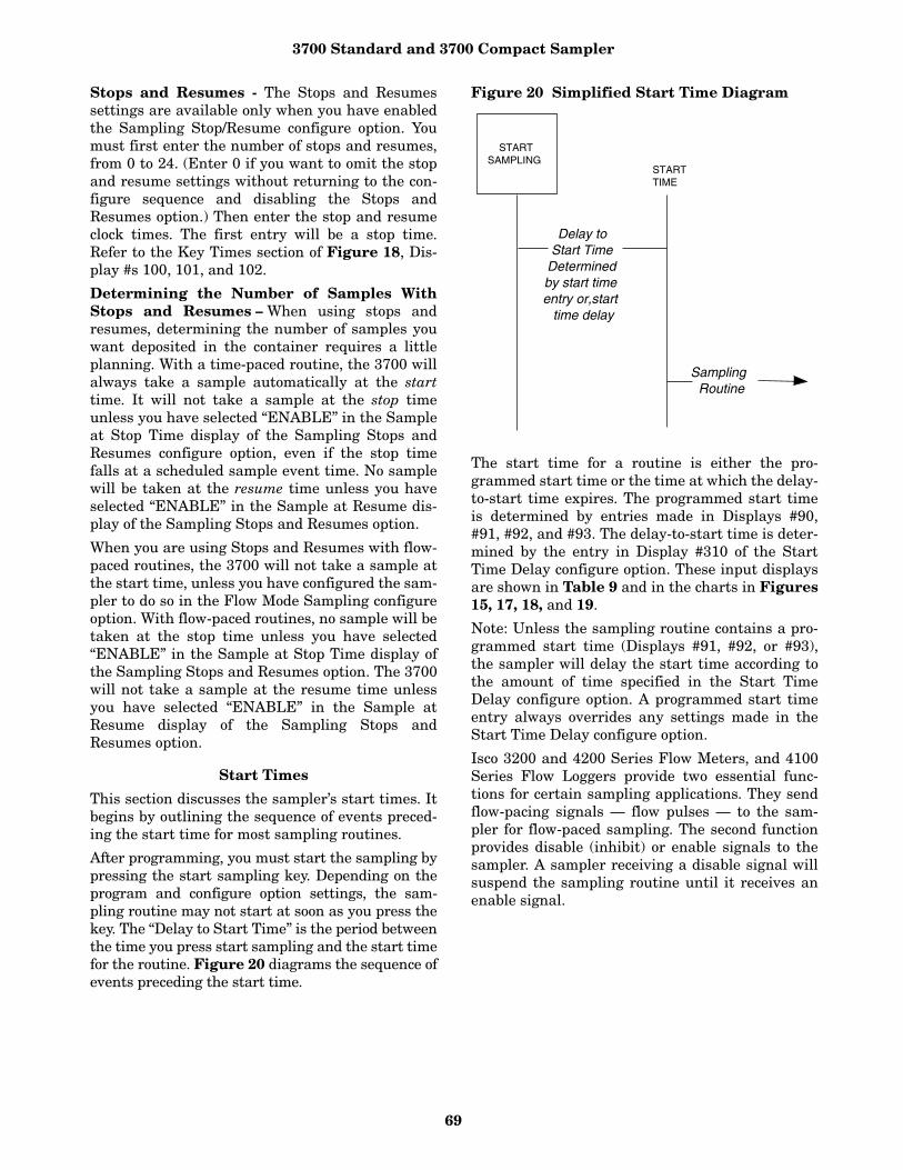
3700 Standard and 3700 Compact Sampler
69
Stops and Resumes - The Stops and Resumessettings are available only when you have enabledthe Sampling Stop/Resume configure option. Youmust first enter the number of stops and resumes,from 0 to 24. (Enter 0 if you want to omit the stopand resume settings without returning to the con-figure sequence and disabling the Stops andResumes option.) Then enter the stop and resumeclock times. The first entry will be a stop time.Refer to the Key Times section of Figure 18, Dis-play #s 100, 101, and 102.
Determining the Number of Samples WithStops and Resumes – When using stops andresumes, determining the number of samples youwant deposited in the container requires a littleplanning. With a time-paced routine, the 3700 willalways take a sample automatically at the starttime. It will not take a sample at the stop timeunless you have selected “ENABLE” in the Sampleat Stop Time display of the Sampling Stops andResumes configure option, even if the stop timefalls at a scheduled sample event time. No samplewill be taken at the resume time unless you haveselected “ENABLE” in the Sample at Resume dis-play of the Sampling Stops and Resumes option.
When you are using Stops and Resumes with flow-paced routines, the 3700 will not take a sample atthe start time, unless you have configured the sam-pler to do so in the Flow Mode Sampling configureoption. With flow-paced routines, no sample will betaken at the stop time unless you have selected“ENABLE” in the Sample at Stop Time display ofthe Sampling Stops and Resumes option. The 3700will not take a sample at the resume time unlessyou have selected “ENABLE” in the Sample atResume display of the Sampling Stops andResumes option.
Start Times
This section discusses the sampler’s start times. Itbegins by outlining the sequence of events preced-ing the start time for most sampling routines.
After programming, you must start the sampling bypressing the start sampling key. Depending on theprogram and configure option settings, the sam-pling routine may not start at soon as you press thekey. The “Delay to Start Time” is the period betweenthe time you press start sampling and the start timefor the routine. Figure 20 diagrams the sequence ofevents preceding the start time.
Figure 20 Simplified Start Time Diagram
The start time for a routine is either the pro-grammed start time or the time at which the delay-to-start time expires. The programmed start timeis determined by entries made in Displays #90,#91, #92, and #93. The delay-to-start time is deter-mined by the entry in Display #310 of the StartTime Delay configure option. These input displaysare shown in Table 9 and in the charts in Figures15, 17, 18, and 19.
Note: Unless the sampling routine contains a pro-grammed start time (Displays #91, #92, or #93),the sampler will delay the start time according tothe amount of time specified in the Start TimeDelay configure option. A programmed start timeentry always overrides any settings made in theStart Time Delay configure option.
Isco 3200 and 4200 Series Flow Meters, and 4100Series Flow Loggers provide two essential func-tions for certain sampling applications. They sendflow-pacing signals — flow pulses — to the sam-pler for flow-paced sampling. The second functionprovides disable (inhibit) or enable signals to thesampler. A sampler receiving a disable signal willsuspend the sampling routine until it receives anenable signal.
STARTSAMPLING
Delay to Start Time
Determined by start time entry or,start
time delay
Sampling Routine
STARTTIME
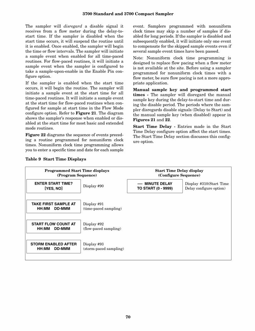
3700 Standard and 3700 Compact Sampler
70
The sampler will disregard a disable signal itreceives from a flow meter during the delay-to-start time. If the sampler is disabled when thestart time occurs, it will suspend the routine untilit is enabled. Once enabled, the sampler will beginthe time or flow intervals. The sampler will initiatea sample event when enabled for all time-pacedroutines. For flow-paced routines, it will initiate asample event when the sampler is configured totake a sample-upon-enable in the Enable Pin con-figure option.
If the sampler is enabled when the start timeoccurs, it will begin the routine. The sampler willinitiate a sample event at the start time for alltime-paced routines. It will initiate a sample eventat the start time for flow-paced routines when con-figured for sample at start time in the Flow Modeconfigure option. Refer to Figure 21. The diagramshows the sampler’s response when enabled or dis-abled at the start time for most basic and extendedmode routines.
Figure 22 diagrams the sequence of events preced-ing a routine programmed for nonuniform clocktimes. Nonuniform clock time programming allowsyou to enter a specific time and date for each sample
event. Samplers programmed with nonuniformclock times may skip a number of samples if dis-abled for long periods. If the sampler is disabled andsubsequently enabled, it will initiate only one eventto compensate for the skipped sample events even ifseveral sample event times have been passed.
Note: Nonuniform clock time programming isdesigned to replace flow pacing when a flow meteris not available at the site. Before using a samplerprogrammed for nonuniform clock times with aflow meter, be sure flow pacing is not a more appro-priate application.
Manual sample key and programmed starttimes - The sampler will disregard the manualsample key during the delay-to-start time and dur-ing the disable period. The periods where the sam-pler disregards disable signals (Delay to Start) andthe manual sample key (when disabled) appear inFigures 21 and 22.
Start Time Delay - Entries made in the StartTime Delay configure option affect the start times.The Start Time Delay section discusses this config-ure option.
Table 9 Start Time Displays
Programmed Start Time displays(Program Sequence)
Start Time Delay display(Configure Sequence)
ENTER START TIME?[YES, NO] Display #90
---- MINUTE DELAYTO START (0 - 9999)
Display #310(Start TimeDelay configure option)
TAKE FIRST SAMPLE ATHH:MM DD-MMM
Display #91 (time-paced sampling)
START FLOW COUNT ATHH:MM DD-MMM
Display #92(flow-paced sampling)
STORM ENABLED AFTERHH:MM DD-MMM
Display #93(storm-paced sampling)
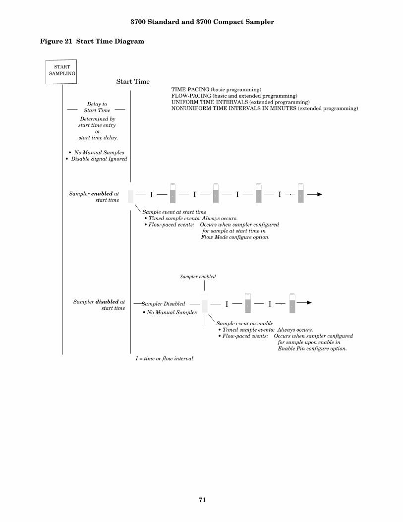
3700 Standard and 3700 Compact Sampler
71
Figure 21 Start Time Diagram
II I I
I I

3700 Standard and 3700 Compact Sampler
72
Figure 22 Start Time Diagram for Nonuniform Clock Time Routines

3700 Standard and 3700 Compact Sampler
73
Storm ProgrammingMany storm water runoff monitoring permitsrequire a first-flush grab sample within the first 30minutes of the storm event and a time- or flow-paced composite sample during the remainder ofthe event. The 3700 Sampler’s STORM pacing isideal for monitoring storm events. Storm pacingallows you to:
• Divide the sampler’s bottles into two groups.The first bottle group receives the first flushgrab sample. The grab sample is always a time-paced sample. The second bottle group receiveseither a flow-paced or time-paced sample.
• Collect samples for the second bottle groupafter collecting the first-flush samples or col-lect samples for both groups at the same time.See Figures 23 and 24.
• Distribute sample volumes to both bottlegroups sequentially or in any of the three mul-tiplexing schemes: bottles-per-sample, sam-ples-per-bottle, or multiple-bottle compositing.
• Use an Isco 3200 or 4200 Series Flow Meter, ora 4100 Series Flow Logger to enable or disablethe sampler according to the level or flow rate ofthe flow stream or to specific amount of rainfall.
• Use a maximum flow interval setting to termi-nate a STORM routine that uses flow-pacedsampling.
The maximum-flow-interval setting affects rou-tines that fill the second bottle group with flow-paced samples. The maximum-flow-interval set-ting limits the amount of time between flow-paced sample events. For example, if the flowrate declines so that the amount of timebetween flow-paced sample events exceeds amaximum-flow-interval setting of two hours, thesampler will terminate the routine when morethan two hours elapses between events. The maximum-flow-interval setting allows thesampler to terminate the routine when the flowrate falls below an acceptable rate or drops offcompletely. This limits the sampling routine toone storm event so that samples from multiplestorm events are not deposited into the bottlegroups.
Storm Sampling Checklist
This section provides two checklists: a list of sug-gested storm monitoring equipment and a briefinstallation checklist. Notes on terminating a rou-tine, manual sampling during a storm routine, anda storm routine’s run state displays follow thechecklist. Example 17 contains a STORM pro-gramming example.
You can find additional information about stormmonitoring installations in the Isco Storm WaterRunoff Monitoring Pocket Guide. The pocket guidecontains the following information:
• How to connect the sampler and rain gauge tothe flow meter;
• Programming examples for flow meters andsamplers;
• How to start and restart the monitoring instal-lation.
Equipment Checklist - The equipment listedbelow is suggested for typical storm-event monitor-ing:
• 3700 Sampler and power source. You can use a 2-, 4-, 8-, or 24-bottle configura-tion for STORM routines (depending on which3700 model you have);
• 3200 or 4200 Series Flow Meter, or a 4100Series Flow Logger, and power source;
• A Sampler-to-Flow Meter Connect Cable. • Optional: Rain gauge with cable and connector
(Rain gauges are required for rain-event trig-gered sampling).
• Optional: FLOWLINK software (requires IBM-compatible computer system).
Although the flow meter contains the sampler-enable conditions most often used in stormwater runoff monitoring, you can use theFLOWLINK system to download many addi-tional sample enable conditions to the flowmeter. Refer to the FLOWLINK InstructionManual for more information.
• Optional: Interrogator communication line kitto connect a computer to the flow meter.
This kit provides the computer-to-flow metercabling. Isco Flow Meters can also be equippedwith a modem to communicate with FLOW-LINK over standard telephone lines.
• Optional: Solar Panel Battery Charger.
Installation Checklist - This checklist summa-rizes the four steps required to set up a storm-mon-itoring installation:
1. Program and install the flow meter. Install therain gauge, if used. You can program 3200 and 4200 Series FlowMeters for sampler enable control conditionsfrom the flow meter front panel or use FLOW-LINK and a computer to download the desiredcondition. The 4100 Series Flow Loggers mustbe programmed with FLOWLINK.Note: You can program the sampler to start theroutine at an exact time and date with a start-time entry. You do not need to use a flow meterto enable the sampler.
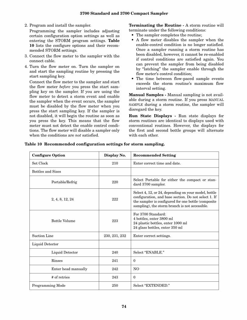
3700 Standard and 3700 Compact Sampler
74
2. Program and install the sampler. Programming the sampler includes adjustingcertain configuration option settings as well asentering the STORM program settings. Table10 lists the configure options and their recom-mended STORM settings.
3. Connect the flow meter to the sampler with theconnect cable.
4. Turn the flow meter on. Turn the sampler onand start the sampling routine by pressing thestart sampling key. Connect the flow meter to the sampler and startthe flow meter before you press the start sam-pling key on the sampler. If you are using theflow meter to detect a storm event and enablethe sampler when the event occurs, the samplermust be disabled by the flow meter when youpress the start sampling key. If the sampler isnot disabled, it will begin the routine as soon asyou press the key. This means that the flowmeter must not detect the enable control condi-tions. The flow meter will disable a sampler onlywhen the conditions are not satisfied.
Terminating the Routine - A storm routine willterminate under the following conditions:
• The sampler completes the routine; • A flow meter disables the sampler when the
enable-control condition is no longer satisfied.Once a sampler running a storm routine hasbeen disabled, however, it cannot be re-enabledif control conditions are satisfied again. Youcan prevent the sampler from being disabledby “latching” the sampler enable through theflow meter’s control condition;
• The time between flow-paced sample eventsexceeds the storm routine’s maximum flowinterval setting.
Manual Samples - Manual sampling is not avail-able during a storm routine. If you press MANUALSAMPLE during a storm routine, the sampler willdisregard the key.
Run State Displays - Run state displays forstorm routines are identical to displays used withconventional routines. However, the displays forthe first and second bottle groups will alternatewith each other.
Table 10 Recommended configuration settings for storm sampling.
Configure Option Display No. Recommended Setting
Set Clock 210 Enter correct time and date.
Bottles and Sizes
Portable/Refrig 220Select Portable for either the compact or stan-dard 3700 sampler.
2, 4, 8, 12, 24 222
Select 4, 12, or 24, depending on your model, bottleconfiguration, and base section. Do not select 1. Ifthe sampler is configured for one bottle (compositesampling), the storm branch is not accessible.
Bottle Volume 223
For 3700 Standard:4 bottles, enter 3800 ml24 plastic bottles, enter 1000 ml24 glass bottles, enter 350 ml
Suction Line 230, 231, 232 Enter correct settings.
Liquid Detector
Liquid Detector 240 Select “ENABLE.”
Rinses 241 0
Enter head manually 242 NO
# of retries 243 0
Programming Mode 250 Select “EXTENDED.”
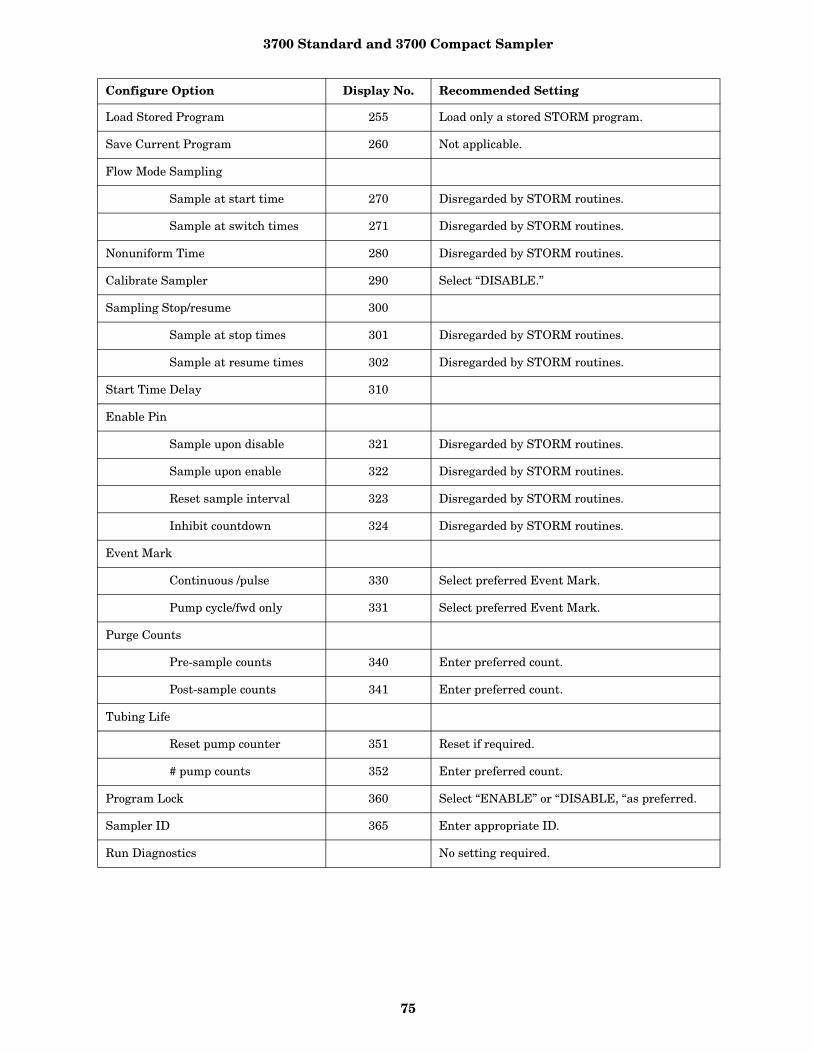
3700 Standard and 3700 Compact Sampler
75
Load Stored Program 255 Load only a stored STORM program.
Save Current Program 260 Not applicable.
Flow Mode Sampling
Sample at start time 270 Disregarded by STORM routines.
Sample at switch times 271 Disregarded by STORM routines.
Nonuniform Time 280 Disregarded by STORM routines.
Calibrate Sampler 290 Select “DISABLE.”
Sampling Stop/resume 300
Sample at stop times 301 Disregarded by STORM routines.
Sample at resume times 302 Disregarded by STORM routines.
Start Time Delay 310
Enable Pin
Sample upon disable 321 Disregarded by STORM routines.
Sample upon enable 322 Disregarded by STORM routines.
Reset sample interval 323 Disregarded by STORM routines.
Inhibit countdown 324 Disregarded by STORM routines.
Event Mark
Continuous /pulse 330 Select preferred Event Mark.
Pump cycle/fwd only 331 Select preferred Event Mark.
Purge Counts
Pre-sample counts 340 Enter preferred count.
Post-sample counts 341 Enter preferred count.
Tubing Life
Reset pump counter 351 Reset if required.
# pump counts 352 Enter preferred count.
Program Lock 360 Select “ENABLE” or “DISABLE, “as preferred.
Sampler ID 365 Enter appropriate ID.
Run Diagnostics No setting required.
Configure Option Display No. Recommended Setting
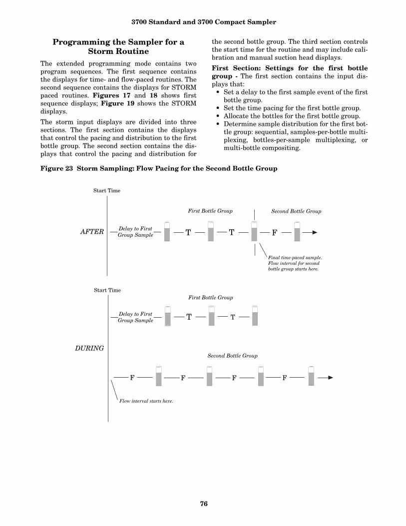
3700 Standard and 3700 Compact Sampler
76
Programming the Sampler for a Storm Routine
The extended programming mode contains twoprogram sequences. The first sequence containsthe displays for time- and flow-paced routines. Thesecond sequence contains the displays for STORMpaced routines. Figures 17 and 18 shows firstsequence displays; Figure 19 shows the STORMdisplays.
The storm input displays are divided into threesections. The first section contains the displaysthat control the pacing and distribution to the firstbottle group. The second section contains the dis-plays that control the pacing and distribution for
the second bottle group. The third section controlsthe start time for the routine and may include cali-bration and manual suction head displays.
First Section: Settings for the first bottlegroup - The first section contains the input dis-plays that:
• Set a delay to the first sample event of the firstbottle group.
• Set the time pacing for the first bottle group.• Allocate the bottles for the first bottle group. • Determine sample distribution for the first bot-
tle group: sequential, samples-per-bottle multi-plexing, bottles-per-sample multiplexing, ormulti-bottle compositing.
Figure 23 Storm Sampling: Flow Pacing for the Second Bottle Group
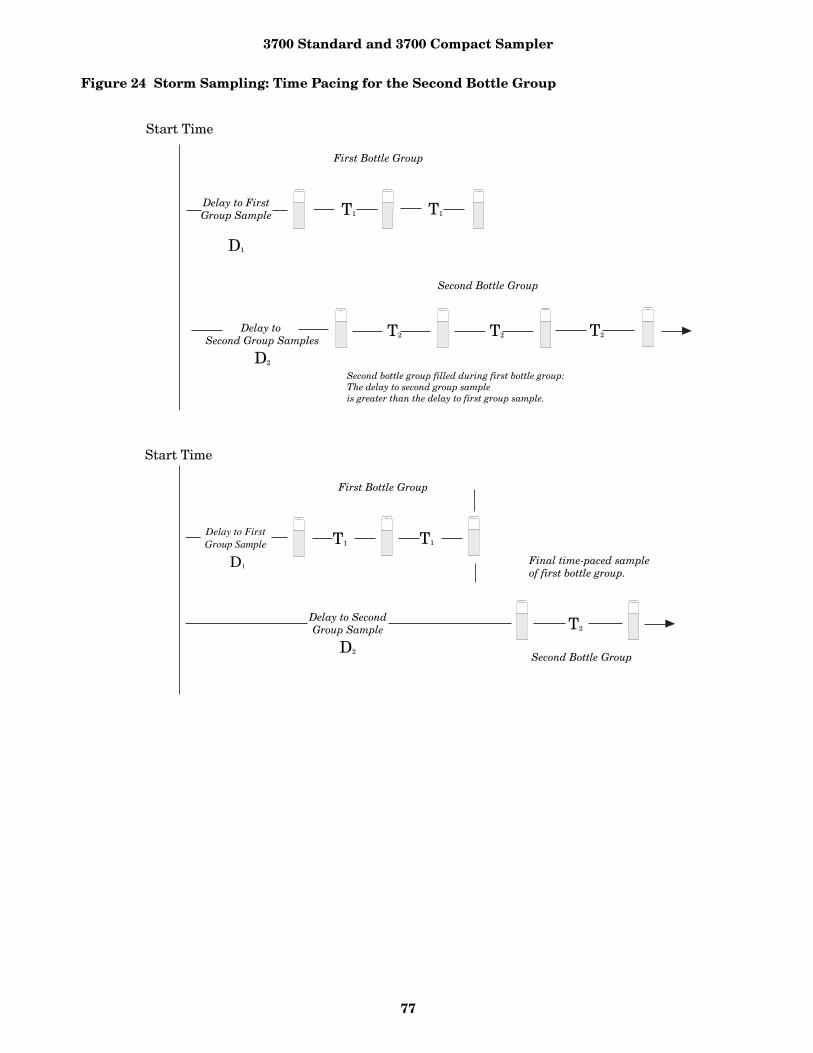
3700 Standard and 3700 Compact Sampler
77
Figure 24 Storm Sampling: Time Pacing for the Second Bottle Group
3700 Standard and 3700 Compact Sampler
78
The “TIME MODE” message marks the beginningof the first section. This message is followed byDisplay #15, below.
Use this display to set amount of time between thetime the sampler is enabled and the first sampledelivered to the first bottle group. (The samplermay be enabled at the start time.)
The acceptable range of values for the delay to firstgroup sample is 0 to 999 minutes. If the delay is 0,the sampler will take the first sample whenenabled by the flow meter. Subsequent time-pacedsamples will occur at the time interval entered inDisplay #23.
How to allocate bottles to the bottle groups -Use the next three displays to determine the boththe sample distribution and the number of bottlesallocated to the bottle groups.
A bottle group can contain one or more bottles. Youcan allocate all bottles but one to the first bottlegroup. The STORM routine will automatically allo-cate the remaining bottles (or bottle) to the secondbottle group. (It obtains the total number of bottlesfrom the bottle number setting in the bottles andsizes configure option.) Refer to the displays above;a 24-bottle sampler programmed to distribute sam-ples to three bottles at two sample events wouldallocate six bottles to the first bottle group. Theremaining 18 bottles to the second bottle group.
Sample distribution and sample volumes forthe first and second bottle groups - STORMsampling supports sequential sampling as well asall three types of multiplexing: bottles-per-samplemultiplexing, samples-per-bottle multiplexing, andmultiple-bottle compositing. These distributionschemes are available for both bottle groups.Because STORM programming is part of theextended programming mode, the sample distribu-tion displays used (Display #s 30 and 31) are iden-tical to other extended mode programmingroutines. Refer to Example 11 for an example of
samples-per-bottle multiplexing, Example 12 forbottles-per-sample multiplexing, and Example 13for multiple-bottle compositing. To enter a samplevolume for the first bottle group, enter the volumein Display #50.
Second Section: Second bottle group - The sec-ond section contains input displays for the secondbottle group. It includes displays that:
• Set the pacing for the second bottle group. • Determine when the sampler begins filling the
second bottle group: during the same timeperiod as the first bottle group or after it fillsthe first bottle group.
• Set the maximum flow interval. • Determine the sample distribution for the second
bottle group: samples-per-bottle multiplexing,bottles-per-sample multiplexing, or multiple-bot-tle compositing.
After you’ve completed the entries for the first bot-tle group, the sampler will present the followingmessage:
This message marks the beginning of the secondsection. It reports the number of bottles allocatedfor the second bottle group and the total volume oftheir combined capacity. The sampler displays thisinformation to help you enter the sample distribu-tion scheme and sample volumes for the secondbottle group. If the remaining number of bottles orthe capacity is not satisfactory, reprogram the firstsection.
Pacing for the Second Bottle Group - The nextdisplay, Display #14, allows you to select time orflow pacing for the second bottle group.
Depending on your selection, the STORM sequencewill follow one of the two paths shown for the sec-ond section in Figure 17 or 18.
Time-Pacing - When you select “TIME” from Dis-play #14, two time-pacing displays (#17 and #24)will follow.
-- MINUTE DELAY TO FIRST GROUP SAMPLE
Display #15
TAKE 2 TIMED SAMPLE EVENTS (1 - MAX)
Display #23
3 BOTTLES PER SAMPLE EVENT (1 - MAX)
Display #30
1 SAMPLES PER BOTTLE(1 - MAX)
Display #31
-- BOTTLES, ----- ml AVAILABLE
[TIME, FLOW]SECOND BOTTLE GROUP
Display #14
____ MINUTE DELAY TOSECOND GROUP SAMPLES
Display #17
SAMPLE INTERVAL OF____ MINUTE (1 - 9999)
Display #24
3700 Standard and 3700 Compact Sampler
79
Use Display #17 to set the delay to the second bot-tle group. Like the delay to the first group sample,the delay to the second group sample determinesthe period between the time the sampler is enabledand the first sample is deposited in the second bot-tle group. You can use this setting to fill the secondbottle group during the same time the sampler fillsthe first bottle group or after the sampler fills thefirst bottle group. Figure 24 shows a time diagramfor a STORM routine that uses time pacing forboth the first and second bottle groups.
To fill the second bottle group after the first, besure amount of time you enter for the delay to sec-ond group is equal to (or greater than, if necessary)the delay to the first group plus the total amount oftime required to fill the first group. The samplerwill begin timing both delays (delay to first anddelay to second bottle group) at the same time.Refer to the lower diagram in Figure 24.
Entries made in Display #s 15, 23, and 24 (“ --MINUTE DELAY TO FIRST GROUP SAMPLE,”“TAKE -- TIMED EVENTS,” and “SAMPLEINTERVALS OF -- MINUTES”) determine theamount of time required to fill the first bottlegroup.
For example, if the delay to the first group were 0and the routine required two timed sample eventsat 30-minute intervals, the sampler would take 30minutes to fill the first bottle group. The first sam-ple event would occur after the programmed delayto group sample; the second sample event wouldoccur 30 minutes later.
Use Display #24 to enter the time interval for thesecond bottle group. You can use any interval; youdo not have to use the same time interval for thesecond bottle group that you used for the firstgroup.
Flow-Pacing for the second bottle group - Ifyou need a flow-paced sample for the second bottlegroup, select “FLOW” from Display #14. Three flowpacing displays (#16, #22, and #110) will follow.
Use Display #16 to determine when the samplerwill begin filling the second bottle group. Select
“DURING” if you want the second bottle groupfilled during the same time period as the first bot-tle group.
Select “AFTER” to begin the flow pacing for thesecond bottle group after the sampler fills the firstbottle group. If you select “DURING,” the samplerwill begin counting flow pulses when it begins tim-ing the delay to first group sample. The samplerwill take the first sample of the second bottle groupas soon at it counts a full flow-pulse interval. If youselect “AFTER,” the sampler will begin countingflow pulses after the last sample event of the firstbottle group. Use Display #22 to enter the flow-pulse interval for the second bottle group.
The third flow paced display allows you to enterthe maximum flow interval. The acceptable rangeof values for the maximum flow interval is oneminute to 99 hours and 59 minutes.
The sampler will terminate the sampling routinewhen the amount of time between flow-paced sam-ples exceeds the limit set for the maximum flowinterval. The maximum flow interval will termi-nate the routine even if all bottles of either bottlegroup have not been filled. Once the sampler ter-minates a routine, the sampler cannot be reen-abled by the flow meter should the flow meterdetect enable control conditions again.
Note: If the second bottle group requires flow-paced samples, the sampler may fill the secondbottle group before it fills the first bottle group.This can occur when the flow rate monitored by theflow meter is higher than anticipated and the flowpulse interval has not been adjusted to reflect thehigher rate. If this occurs, the sampler will con-tinue the first bottle group until all samples havebeen taken. You can adjust the pulse interval by
• Reprogramming the flow meter to change thenumber of flow pulses sent to the sampler bythe flow meter.
• Reprogramming the sampler to change theflow pulse interval in the flow-pacing segmentof the STORM routine.
• Reprogramming both the flow meter and thesampler.
STORM Key Times - The third section, STORMKey Times, contains the displays used to:
• Enter suction-head measurements;• Enable the calibration routine;• Enter a start time for the storm routine.
[DURING, AFTER]TIME MODE
Display #16
SAMPLE EVERY ---- PULSES (1 - 9999)
Display #22
MAX FLOW INTERVAL OF__ HOURS __ MINUTES
Display #110

3700 Standard and 3700 Compact Sampler
80
The input displays of the STORM programsequence vary according to configure option set-tings. The first two displays (“SUCTION HEADOF -- FEET” and “CALIBRATE SAMPLE VOL-UME”) appear if the sampler is configured to addthem to the storm program sequence. Entries inthe Liquid Detector configure option and the Cali-brate Sampler configure option add or excludethese displays from the sequence. Example 17does not include these displays.
To enter a specific start time for the routine, select“YES” in Display #90 (illustrated in Step 19 ofExample 17). The sampler will prompt you to entera start time with Display #93 (step 20). If you select“NO,” the start time will be delayed by the amountset in the Start Time Delay configure option.
After you’ve made these entries, the sampler willpresent the “PROGRAMMING SEQUENCE COM-PLETE” message and return to standby.
Programmed start times, start time delays,and delays to group sample - Samplers pro-grammed for storm sampling respond to start-timedelays and programmed start times in the sameway as samplers programmed for any other basicor extended mode routines.
The sampler will delay the storm routine until thestart time entered in the third segment of theSTORM sequence. (See Display #93.) If the sam-pler is enabled by the flow meter at the start time,the sampler will begin to time the delay to the firstbottle group. If the sampler is disabled by the flowmeter at the start time, the sampler will suspendthe routine until it becomes enabled. Once thesampler is enabled by the flow meter, the samplerwill begin the delay to first timed sample eventand continue the STORM routine.
STORM sampling routine has four delay periodsthat vary slightly with the programming entries.Every STORM routine will have a delay to starttime and delay to first group sample.
Depending on whether the second bottle group istime paced or flow paced, the third delay periodwill be either the delay to second group sample orthe “During/After” delay.
• Delay-to-Start Time. The start time is simplythe time the sampler begins the routine. Thesampler begins timing the delay-to-start timewhen you press the start sampling key. The sam-pler will not check for an enable or disable sig-nal from a flow meter, Liquid Level Actuator,or another sampler until the start time.
The delay-to-start time is the amount of timebetween the time you press the start sampling
key and the start time. The delay-to-start timeis determined by the programmed start-timeentry for the STORM routine (Display #93) orthe Start Time Delay configure option. The Start Time Delay, set in the configureoption, can be from 0 to 999 minutes long. A pro-grammed start time can be any date within 30days of the sampler’s current date.
• Delay-to-First-Group Sample. The delay-to-first-group sample is the period between thetime the sampler is enabled (not the starttime) and the time first sample volume is deliv-ered to the first bottle group. Your entry in Dis-play #15 determines the Delay to First Group.
• Delay-to-Second-Group Samples. The delay-to-second-group sample is the period between thetime the sampler is enabled (not the starttime) and the time the first sample volume isdelivered to the second bottle group. This delayis determined by your entry in Display #17.You can enter a delay-to-second-group sampleonly for time-paced second bottle groups.
• DURING/AFTER. This delay affects flow-paced second bottle groups. Like the delay tosecond group sample, the during/after delaydetermines when the sampler begins samplingfor the second bottle group. Because the flow-paced sampling can consume unpredictableamounts of time, the storm routine must usetwo specific events to mark the beginning ofthe flow intervals. These events are the timethe sampler is enabled and the time the sam-pler completes the first bottle group.
If you want the sampler to fill the second bottlegroup during the first bottle group, select “DUR-ING” from Display #16. The sampler will begincounting flow pulses when the sampler isenabled. (If the sampler is enabled at the starttime, the sampler starts counting flow pulses atthe start time.) If you want the sampler to fill the second groupafter the sampler fills the first bottle group,select “AFTER.” The sampler will begin count-ing flow pulses after it fills the first bottle group.
Programming ExamplesThe following examples demonstrate the stepsused to program the sampler for several differentsampling routines in the extended programmingmode. Each programming example concludes withthe run state displays that appear for that routine.
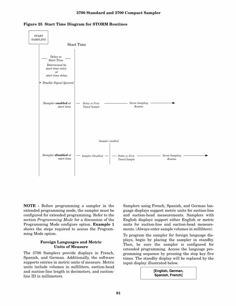
3700 Standard and 3700 Compact Sampler
81
Figure 25 Start Time Diagram for STORM Routines
NOTE - Before programming a sampler in theextended programming mode, the sampler must beconfigured for extended programming. Refer to thesection Programming Mode for a discussion of theProgramming Mode configure option. Example 1shows the steps required to access the Program-ming Mode option.
Foreign Languages and Metric Units of Measure
The 3700 Samplers provide displays in French,Spanish, and German. Additionally, the softwaresupports entries in metric units of measure. Metricunits include volumes in milliliters, suction-headand suction-line length in decimeters, and suction-line ID in millimeters.
Samplers using French, Spanish, and German lan-guage displays support metric units for suction-lineand suction-head measurements. Samplers withEnglish displays support either English or metricunits for suction-line and suction-head measure-ments. (Always enter sample volumes in milliliters).
To program the sampler for foreign language dis-plays, begin by placing the sampler in standby.Then, be sure the sampler is configured forextended programming. Access the language pro-gramming sequence by pressing the stop key fivetimes. The standby display will be replaced by theinput display illustrated below.
[English, German,Spanish, French]
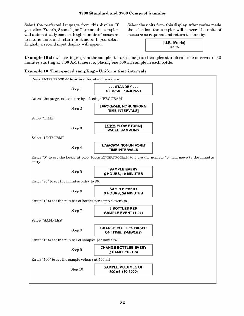
3700 Standard and 3700 Compact Sampler
82
Select the preferred language from this display. Ifyou select French, Spanish, or German, the samplerwill automatically convert English units of measureto metric units and return to standby. If you selectEnglish, a second input display will appear.
Select the units from this display. After you’ve madethe selection, the sampler will convert the units ofmeasure as required and return to standby.
Example 10 shows how to program the sampler to take time-paced samples at uniform time intervals of 30minutes starting at 8:00 AM tomorrow, placing one 500 ml sample in each bottle.
Example 10 Time-paced sampling – Uniform time intervals
[U.S., Metric]Units
Press ENTER/PROGRAM to access the interactive state
Step 1. . . STANDBY . . .
10:34:50 19-JUN-91
Access the program sequence by selecting “PROGRAM”
Step 2 [PROGRAM, NONUNIFORM TIME INTERVALS]
Select “TIME”
Step 3[TIME, FLOW STORM]
PACED SAMPLING
Select “UNIFORM”
Step 4[UNIFORM, NONUNIFORM]
TIME INTERVALS
Enter “0” to set the hours at zero. Press ENTER/PROGRAM to store the number “0” and move to the minutesentry.
Step 5SAMPLE EVERY
0 HOURS, 10 MINUTES
Enter “30” to set the minutes entry to 30.
Step 6SAMPLE EVERY
0 HOURS, 30 MINUTES
Enter “1” to set the number of bottles per sample event to 1
Step 7 1 BOTTLES PERSAMPLE EVENT (1-24)
Select “SAMPLES”
Step 8CHANGE BOTTLES BASED
ON [TIME, SAMPLES}
Enter “1” to set the number of samples per bottle to 1.
Step 9CHANGE BOTTLES EVERY
1 SAMPLES (1-8)
Enter “500” to set the sample volume at 500 ml.
Step 10 SAMPLE VOLUMES OF500 ml (10-1000)
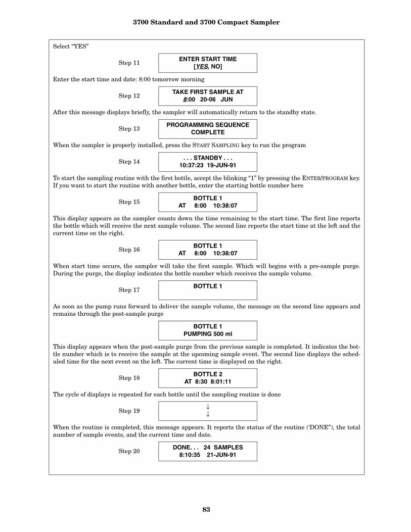
3700 Standard and 3700 Compact Sampler
83
Select “YES”
Step 11 ENTER START TIME[YES, NO]
Enter the start time and date: 8:00 tomorrow morning
Step 12TAKE FIRST SAMPLE AT
8:00 20-06 JUN
After this message displays briefly, the sampler will automatically return to the standby state.
Step 13PROGRAMMING SEQUENCE
COMPLETE
When the sampler is properly installed, press the START SAMPLING key to run the program
Step 14 . . . STANDBY . . .10:37:23 19-JUN-91
To start the sampling routine with the first bottle, accept the blinking “1” by pressing the ENTER/PROGRAM key.If you want to start the routine with another bottle, enter the starting bottle number here
Step 15 BOTTLE 1AT 8:00 10:38:07
This display appears as the sampler counts down the time remaining to the start time. The first line reportsthe bottle which will receive the next sample volume. The second line reports the start time at the left and thecurrent time on the right.
Step 16BOTTLE 1
AT 8:00 10:38:07
When start time occurs, the sampler will take the first sample. Which will begins with a pre-sample purge.During the purge, the display indicates the bottle number which receives the sample volume.
Step 17BOTTLE 1
As soon as the pump runs forward to deliver the sample volume, the message on the second line appears andremains through the post-sample purge
BOTTLE 1PUMPING 500 ml
This display appears when the post-sample purge from the previous sample is completed. It indicates the bot-tle number which is to receive the sample at the upcoming sample event. The second line displays the sched-uled time for the next event on the left. The current time is displayed on the right.
Step 18 BOTTLE 2AT 8:30 8:01:11
The cycle of displays is repeated for each bottle until the sampling routine is done
Step 19↓↓
When the routine is completed, this message appears. It reports the status of the routine (‘DONE”), the totalnumber of sample events, and the current time and date.
Step 20DONE. . . 24 SAMPLES
8:10:35 21-JUN-91

3700 Standard and 3700 Compact Sampler
84
Example 11 shows how to program the sampler to take time-paced samples at uniform time intervals of 15minutes. At each sample event, one bottle will receive a sample volume of 75 ml. The bottles are to beswitched every hour so that four sample volumes have been deposited into each bottle. The sampling rou-tine will start according to the programmed start-time delay set in the Start Time Delay configure option.
Example 11 Time-paced multiplexed (samples-per-bottle) sampling.
Press ENTER/PROGRAM to access the interactive state.
Step 1. . . STANDBY . . .
5:37:23 19-JUN-91
Access the program sequence by selecting “PROGRAM.”
Step 2[PROGRAM, CONFIGURE]
SAMPLER
Select “TIME.”
Step 3[TIME, FLOW, STORM]
PACED SAMPLING
Select “UNIFORM.”
Step 4[UNIFORM, NONUNIFORM]
TIME INTERVALS
Enter “0” to set the hours at zero. Press ENTER/PROGRAM to store the number “0” and move to the minutesentry.
Step 5SAMPLE EVERY
0 HOURS,30 MINUTES
Enter “15” to set the minutes entry to 15.
Step 6SAMPLE EVERY
0 HOURS,15 MINUTES
Enter “1” to set the number of bottles per sample event to 1.
Step 71 BOTTLES PER
SAMPLE EVENT (1 - 24)
Select “SAMPLES.” We recommend bottle set changes be based on samples for time-paced sampling routines.
Step 8CHANGE BOTTLES BASED
ON [TIME, SAMPLES]
Enter “4” to set the number of samples per bottle to 4.
Step 9CHANGE BOTTLES EVERY
4 SAMPLES (1 - 8)
Enter “75” to set the sample volume at 75 ml.
Step 10SAMPLE VOLUMES OF
75 ml (10 - 250)
Select “NO.”
Step 11ENTER START TIME?
[YES, NO]

3700 Standard and 3700 Compact Sampler
85
After this message is displayed briefly, the sampler will automatically return to the standby state.
Step 12PROGRAMMING SEQUENCE
COMPLETE
After the sampler is properly installed, press the START SAMPLING key to run the program.
Step 13. . . STANDBY . . .
5:39:25 20-JUN-91
To start the sampling routine with the first bottle, accept the blinking “1” by pressing the ENTER/PROGRAM key.If you want to start the routine with another bottle, enter the starting bottle number here.
Step 14START SAMPLINGAT BOTTLE 1 (1-24)
This display is used with samples-per-bottle multiplexing. The first line indicate the number of the upcomingsample and the total number of samples each bottle is to receive. It also indicates the current bottle number.Thus, this display indicates that the upcoming sample is the first of four samples and bottle one is to receivethe next sample. The second line indicates the scheduled time of the sample. The current time is shown in theright corner as the sampler counts down to the next sample event time.
Step 151 OF 4, BOTTLE 1AT 5:41 5:39:33
When the scheduled sample event time arrives, the second line will disappear while the sampler completesthe pre-sample purge.
Step 161 OF 4, BOTTLE 1
When the pump begins to pump forward to deliver the sample, the second line will indicate the sample deliv-ery by displaying the word “PUMPING” and the sample volume being delivered. The message remains duringthe sample delivery and post-sample purge.
1 OF 4, BOTTLE 1PUMPING 75 ml
When the sampling cycle is completed, the display will indicate the upcoming sample, shown here. This dis-play indicates that the upcoming sample is the second of four samples; the current sample bottle is bottle 1.The sample event is scheduled for 6:15. The current time is just after 6:00.
Step 172 OF 4, BOTTLE 1AT 6:15 6:00:26
The next displays illustrated here, in steps 18 and 19, show the displays as the sample volumes are depositedin bottle 1.
Step 182 OF 4, BOTTLE 1
2 OF 4, BOTTLE 1PUMPING 75 ml
Step 193 OF 4, BOTTLE 1AT 6:30 6:15:27
↓↓
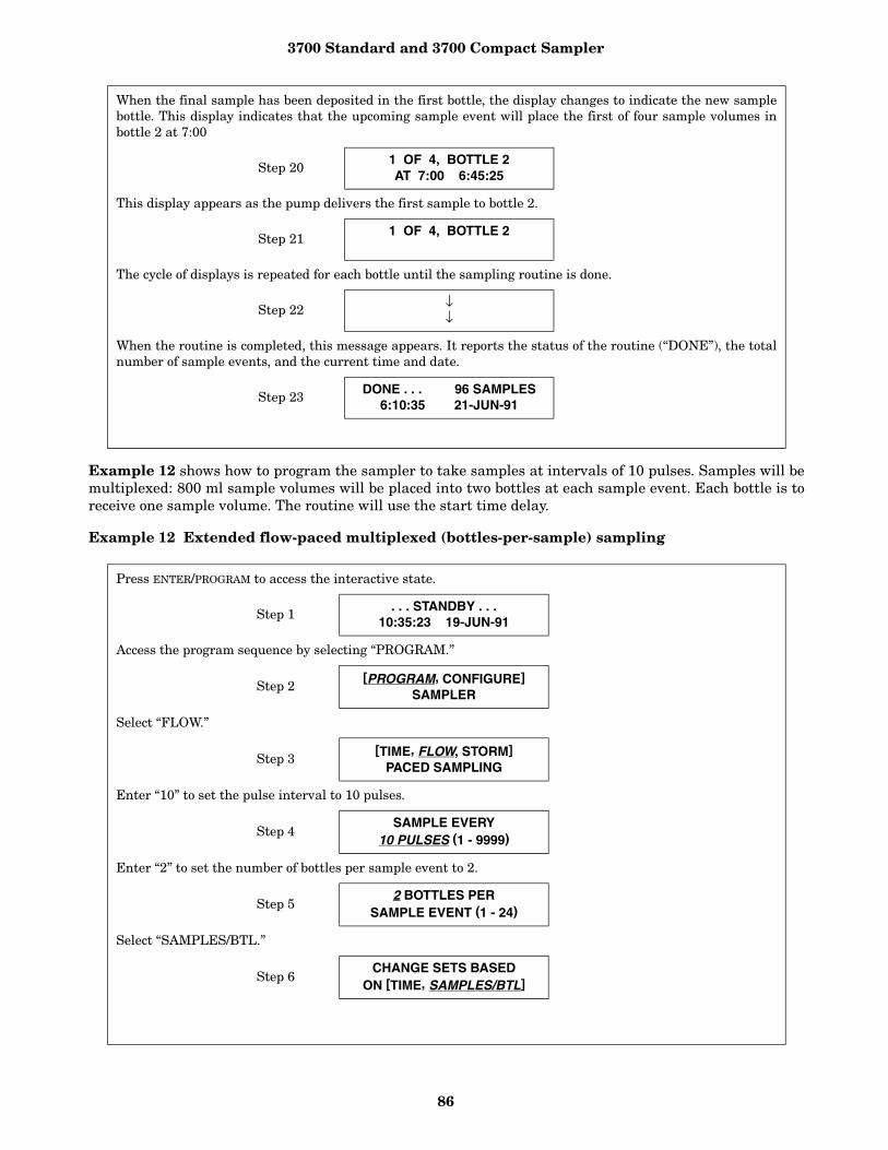
3700 Standard and 3700 Compact Sampler
86
Example 12 shows how to program the sampler to take samples at intervals of 10 pulses. Samples will bemultiplexed: 800 ml sample volumes will be placed into two bottles at each sample event. Each bottle is toreceive one sample volume. The routine will use the start time delay.
Example 12 Extended flow-paced multiplexed (bottles-per-sample) sampling
When the final sample has been deposited in the first bottle, the display changes to indicate the new samplebottle. This display indicates that the upcoming sample event will place the first of four sample volumes inbottle 2 at 7:00
Step 201 OF 4, BOTTLE 2AT 7:00 6:45:25
This display appears as the pump delivers the first sample to bottle 2.
Step 211 OF 4, BOTTLE 2
The cycle of displays is repeated for each bottle until the sampling routine is done.
Step 22 ↓↓
When the routine is completed, this message appears. It reports the status of the routine (“DONE”), the totalnumber of sample events, and the current time and date.
Step 23 DONE . . . 96 SAMPLES6:10:35 21-JUN-91
Press ENTER/PROGRAM to access the interactive state.
Step 1 . . . STANDBY . . .10:35:23 19-JUN-91
Access the program sequence by selecting “PROGRAM.”
Step 2[PROGRAM, CONFIGURE]
SAMPLER
Select “FLOW.”
Step 3[TIME, FLOW, STORM]
PACED SAMPLING
Enter “10” to set the pulse interval to 10 pulses.
Step 4SAMPLE EVERY
10 PULSES (1 - 9999)
Enter “2” to set the number of bottles per sample event to 2.
Step 52 BOTTLES PER
SAMPLE EVENT (1 - 24)
Select “SAMPLES/BTL.”
Step 6CHANGE SETS BASED
ON [TIME, SAMPLES/BTL]
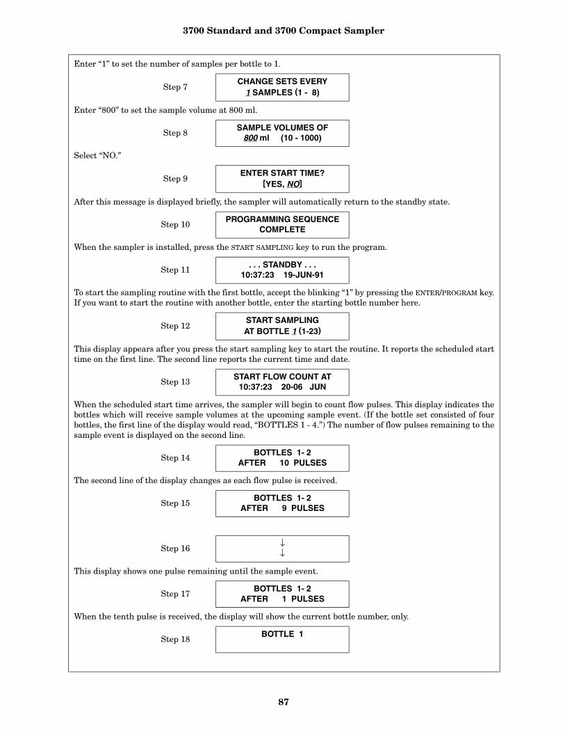
3700 Standard and 3700 Compact Sampler
87
Enter “1” to set the number of samples per bottle to 1.
Step 7CHANGE SETS EVERY
1 SAMPLES (1 - 8)
Enter “800” to set the sample volume at 800 ml.
Step 8SAMPLE VOLUMES OF
800 ml (10 - 1000)
Select “NO.”
Step 9ENTER START TIME?
[YES, NO]
After this message is displayed briefly, the sampler will automatically return to the standby state.
Step 10PROGRAMMING SEQUENCE
COMPLETE
When the sampler is installed, press the START SAMPLING key to run the program.
Step 11 . . . STANDBY . . .10:37:23 19-JUN-91
To start the sampling routine with the first bottle, accept the blinking “1” by pressing the ENTER/PROGRAM key.If you want to start the routine with another bottle, enter the starting bottle number here.
Step 12START SAMPLINGAT BOTTLE 1 (1-23)
This display appears after you press the start sampling key to start the routine. It reports the scheduled starttime on the first line. The second line reports the current time and date.
Step 13 START FLOW COUNT AT10:37:23 20-06 JUN
When the scheduled start time arrives, the sampler will begin to count flow pulses. This display indicates thebottles which will receive sample volumes at the upcoming sample event. (If the bottle set consisted of fourbottles, the first line of the display would read, “BOTTLES 1 - 4.”) The number of flow pulses remaining to thesample event is displayed on the second line.
Step 14BOTTLES 1- 2
AFTER 10 PULSES
The second line of the display changes as each flow pulse is received.
Step 15BOTTLES 1- 2
AFTER 9 PULSES
Step 16 ↓↓
This display shows one pulse remaining until the sample event.
Step 17BOTTLES 1- 2
AFTER 1 PULSES
When the tenth pulse is received, the display will show the current bottle number, only.
Step 18BOTTLE 1

3700 Standard and 3700 Compact Sampler
88
In Example 13, samples are to be taken at intervals of 1,000 flow pulses. Samples will be multiplexed byplacing 100 ml sample volumes into two bottles at each sample event. To avoid missing any samples, thesampling routine starts immediately after you press the start sampling key. To place the bottle set changesat the top of the hour, the sampler will be allowed to take samples until 12:00, the time of the first bottle setchange. After the first change, bottle sets will change every two hours.
Note: The number of samples in each bottle set will vary as the flow rate varies. If at least one sample isdesired in each bottle, the sampler should be directed to take a sample at the start and switch times. Seethe section Flow Mode Sampling, which describes this option.
Example 13 Flow-paced sampling with bottle sets based on time.
When the pump begins to run forward to deliver the sample volume, the second line appears. After the pumpcompletes the sample delivery, it reverses to purge the liquid from the pump tube past the liquid detector. Thesuction line is not completely purged; instead, the liquid is pumped just past the liquid detector. At the end ofthe pump tube purge, the distributor moves to the next bottle of the set. The display remains unchanged untilthe distributor relocates to the next bottle of the set.
BOTTLE 1PUMPING 800 ml
As the distributor moves to the next bottle, the bottle number reported in the display changes to indicate thebottle number. The message, “PUMPING 800 ml,” will remain on the display. When the distributor reachesthe correct position over the current bottle, the pump runs forward to deliver the sample volume. When thedelivery is completed, the pump reverses to complete the post-sample purge.
Step 19 BOTTLE 2PUMPING 800 ml
At the end of the post-sample purge, the display changes to indicate the bottle numbers of the next bottle set.The display will change as it receives each flow pulse.
Step 20 BOTTLES 3- 4AFTER 10 PULSES
The cycle is repeated until the sampling routine is completed.
Step 21 ↓↓
When the routine is complete, the display will indicate the status of the routine (“DONE”), the number of sam-ple events, and the current time and date.
Step 22DONE . . . 12 SAMPLES
6:10:35 21-JUN-91
Press ENTER/PROGRAM to access the interactive state.
Step 1. . . STANDBY . . .
10:34:50 19-JUN-91
Access the program sequence by selecting “PROGRAM.”
Step 2[PROGRAM, CONFIGURE]
SAMPLER
Select “FLOW.”
Step 3[TIME, FLOW, STORM]
PACED SAMPLING
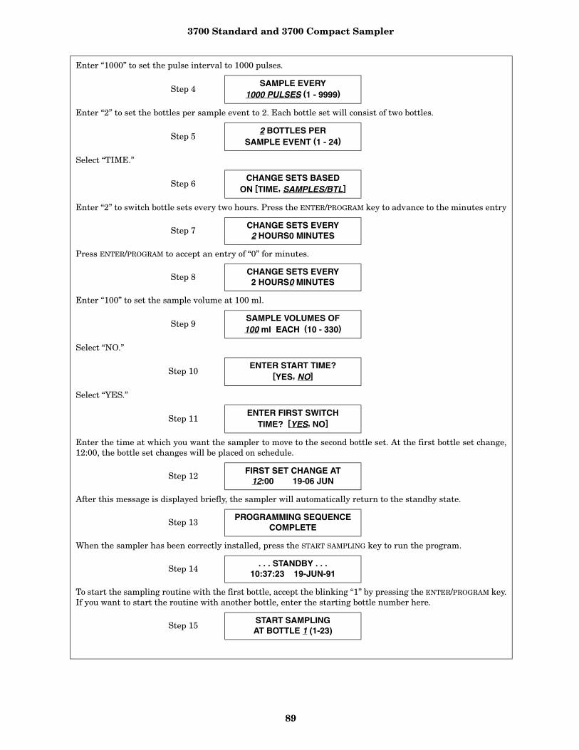
3700 Standard and 3700 Compact Sampler
89
Enter “1000” to set the pulse interval to 1000 pulses.
Step 4SAMPLE EVERY
1000 PULSES (1 - 9999)
Enter “2” to set the bottles per sample event to 2. Each bottle set will consist of two bottles.
Step 52 BOTTLES PER
SAMPLE EVENT (1 - 24)
Select “TIME.”
Step 6CHANGE SETS BASED
ON [TIME, SAMPLES/BTL]
Enter “2” to switch bottle sets every two hours. Press the ENTER/PROGRAM key to advance to the minutes entry
Step 7 CHANGE SETS EVERY2 HOURS0 MINUTES
Press ENTER/PROGRAM to accept an entry of “0” for minutes.
Step 8CHANGE SETS EVERY2 HOURS0 MINUTES
Enter “100” to set the sample volume at 100 ml.
Step 9SAMPLE VOLUMES OF100 ml EACH (10 - 330)
Select “NO.”
Step 10ENTER START TIME?
[YES, NO]
Select “YES.”
Step 11ENTER FIRST SWITCH
TIME? [YES, NO]
Enter the time at which you want the sampler to move to the second bottle set. At the first bottle set change,12:00, the bottle set changes will be placed on schedule.
Step 12 FIRST SET CHANGE AT12:00 19-06 JUN
After this message is displayed briefly, the sampler will automatically return to the standby state.
Step 13PROGRAMMING SEQUENCE
COMPLETE
When the sampler has been correctly installed, press the START SAMPLING key to run the program.
Step 14. . . STANDBY . . .
10:37:23 19-JUN-91
To start the sampling routine with the first bottle, accept the blinking “1” by pressing the ENTER/PROGRAM key.If you want to start the routine with another bottle, enter the starting bottle number here.
Step 15START SAMPLINGAT BOTTLE 1 (1-23)
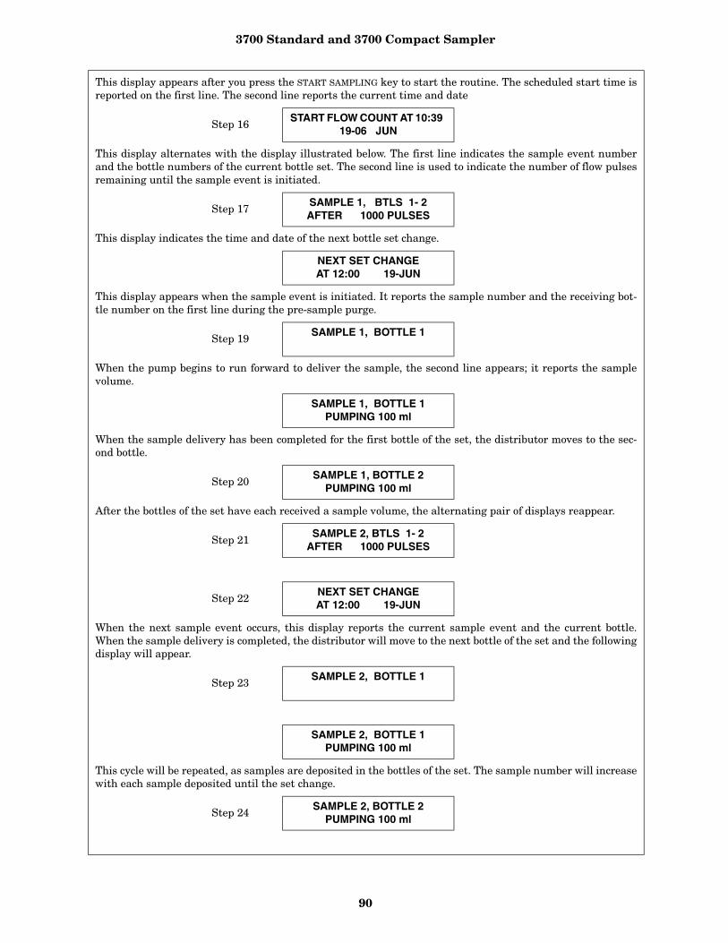
3700 Standard and 3700 Compact Sampler
90
This display appears after you press the START SAMPLING key to start the routine. The scheduled start time isreported on the first line. The second line reports the current time and date
Step 16START FLOW COUNT AT 10:39
19-06 JUN
This display alternates with the display illustrated below. The first line indicates the sample event numberand the bottle numbers of the current bottle set. The second line is used to indicate the number of flow pulsesremaining until the sample event is initiated.
Step 17SAMPLE 1, BTLS 1- 2AFTER 1000 PULSES
This display indicates the time and date of the next bottle set change.
NEXT SET CHANGE AT 12:00 19-JUN
This display appears when the sample event is initiated. It reports the sample number and the receiving bot-tle number on the first line during the pre-sample purge.
Step 19SAMPLE 1, BOTTLE 1
When the pump begins to run forward to deliver the sample, the second line appears; it reports the samplevolume.
SAMPLE 1, BOTTLE 1PUMPING 100 ml
When the sample delivery has been completed for the first bottle of the set, the distributor moves to the sec-ond bottle.
Step 20SAMPLE 1, BOTTLE 2
PUMPING 100 ml
After the bottles of the set have each received a sample volume, the alternating pair of displays reappear.
Step 21SAMPLE 2, BTLS 1- 2
AFTER 1000 PULSES
Step 22 NEXT SET CHANGE AT 12:00 19-JUN
When the next sample event occurs, this display reports the current sample event and the current bottle.When the sample delivery is completed, the distributor will move to the next bottle of the set and the followingdisplay will appear.
Step 23SAMPLE 2, BOTTLE 1
SAMPLE 2, BOTTLE 1PUMPING 100 ml
This cycle will be repeated, as samples are deposited in the bottles of the set. The sample number will increasewith each sample deposited until the set change.
Step 24 SAMPLE 2, BOTTLE 2PUMPING 100 ml
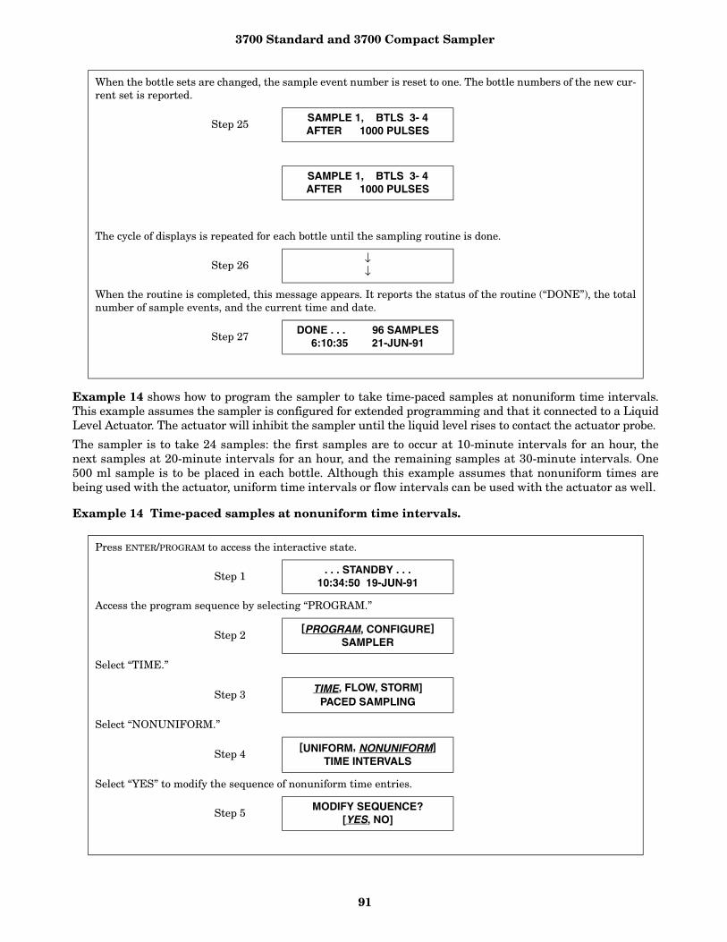
3700 Standard and 3700 Compact Sampler
91
Example 14 shows how to program the sampler to take time-paced samples at nonuniform time intervals.This example assumes the sampler is configured for extended programming and that it connected to a LiquidLevel Actuator. The actuator will inhibit the sampler until the liquid level rises to contact the actuator probe.
The sampler is to take 24 samples: the first samples are to occur at 10-minute intervals for an hour, thenext samples at 20-minute intervals for an hour, and the remaining samples at 30-minute intervals. One500 ml sample is to be placed in each bottle. Although this example assumes that nonuniform times arebeing used with the actuator, uniform time intervals or flow intervals can be used with the actuator as well.
Example 14 Time-paced samples at nonuniform time intervals.
When the bottle sets are changed, the sample event number is reset to one. The bottle numbers of the new cur-rent set is reported.
Step 25SAMPLE 1, BTLS 3- 4AFTER 1000 PULSES
SAMPLE 1, BTLS 3- 4AFTER 1000 PULSES
The cycle of displays is repeated for each bottle until the sampling routine is done.
Step 26↓↓
When the routine is completed, this message appears. It reports the status of the routine (“DONE”), the totalnumber of sample events, and the current time and date.
Step 27DONE . . . 96 SAMPLES
6:10:35 21-JUN-91
Press ENTER/PROGRAM to access the interactive state.
Step 1 . . . STANDBY . . .10:34:50 19-JUN-91
Access the program sequence by selecting “PROGRAM.”
Step 2[PROGRAM, CONFIGURE]
SAMPLER
Select “TIME.”
Step 3 TIME, FLOW, STORM]PACED SAMPLING
Select “NONUNIFORM.”
Step 4[UNIFORM, NONUNIFORM]
TIME INTERVALS
Select “YES” to modify the sequence of nonuniform time entries.
Step 5MODIFY SEQUENCE?
[YES, NO]
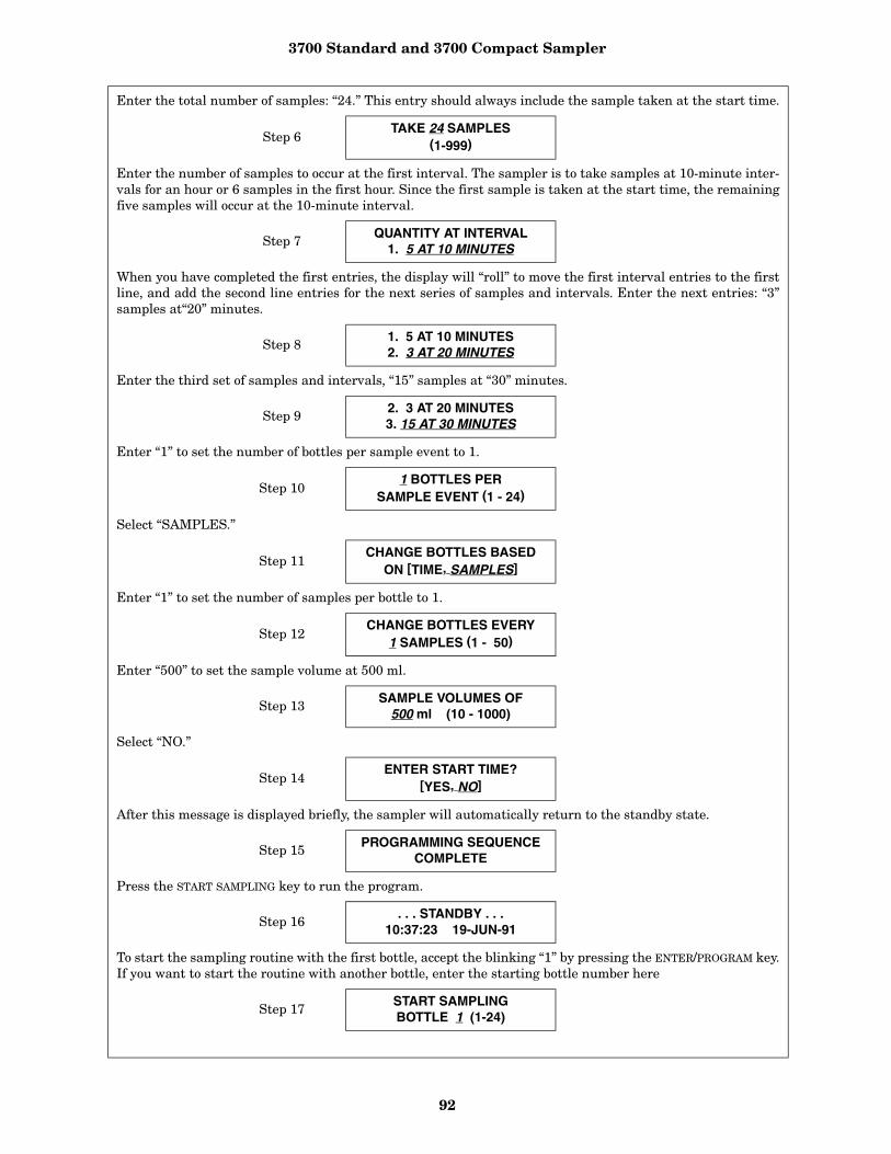
3700 Standard and 3700 Compact Sampler
92
Enter the total number of samples: “24.” This entry should always include the sample taken at the start time.
Step 6TAKE 24 SAMPLES
(1-999)
Enter the number of samples to occur at the first interval. The sampler is to take samples at 10-minute inter-vals for an hour or 6 samples in the first hour. Since the first sample is taken at the start time, the remainingfive samples will occur at the 10-minute interval.
Step 7 QUANTITY AT INTERVAL1. 5 AT 10 MINUTES
When you have completed the first entries, the display will “roll” to move the first interval entries to the firstline, and add the second line entries for the next series of samples and intervals. Enter the next entries: “3”samples at“20” minutes.
Step 81. 5 AT 10 MINUTES2. 3 AT 20 MINUTES
Enter the third set of samples and intervals, “15” samples at “30” minutes.
Step 9 2. 3 AT 20 MINUTES3. 15 AT 30 MINUTES
Enter “1” to set the number of bottles per sample event to 1.
Step 101 BOTTLES PER
SAMPLE EVENT (1 - 24)
Select “SAMPLES.”
Step 11CHANGE BOTTLES BASED
ON [TIME, SAMPLES]
Enter “1” to set the number of samples per bottle to 1.
Step 12CHANGE BOTTLES EVERY
1 SAMPLES (1 - 50)
Enter “500” to set the sample volume at 500 ml.
Step 13 SAMPLE VOLUMES OF500 ml (10 - 1000)
Select “NO.”
Step 14ENTER START TIME?
[YES, NO]
After this message is displayed briefly, the sampler will automatically return to the standby state.
Step 15 PROGRAMMING SEQUENCECOMPLETE
Press the START SAMPLING key to run the program.
Step 16 . . . STANDBY . . .
10:37:23 19-JUN-91
To start the sampling routine with the first bottle, accept the blinking “1” by pressing the ENTER/PROGRAM key.If you want to start the routine with another bottle, enter the starting bottle number here
Step 17START SAMPLING BOTTLE 1 (1-24)

3700 Standard and 3700 Compact Sampler
93
This display appears while the Actuator is inhibiting the sampler. The second line indicates the current timeand date.
Step 18SAMPLER INHIBITED!
10:35 20-JUN-91
This display appears when the sampler becomes enabled and counts down the time remaining to the starttime. The first line reports the bottle which will receive the next sample volume. The second line reports thestart time at the left and the current time on the right.
Step 19BOTTLE 1
AT 11:26 11:25:47
When the start time occurs, the sampler will take the first sample. The sample event cycle begins with a pre-sample purge. During the purge, the display indicates the receiving bottle number.
Step 20BOTTLE 1
As soon as the pump runs forward to deliver the sample volume, the message on the second line appears. Thismessage remains through the post-sample purge
BOTTLE 1PUMPING 500 ml
This display appears when the post-sample purge from the previous sample event is completed. It indicatesthe bottle number which is to receive the sample at the upcoming sample event. The second line displays thescheduled time for the next event on the left; the current time is displayed on the right.
Step 21BOTTLE 2
AT 11:36: 11:26:11
The cycle of displays is repeated for each bottle until the sampling routine is done.
Step 22 ↓↓
When the routine is completed, this message appears. It reports the status of the routine, “DONE;” the totalnumber of sample events; and the current time and date.
Step 23 DONE . . . 24 SAMPLES8:10:35 21-JUN-91
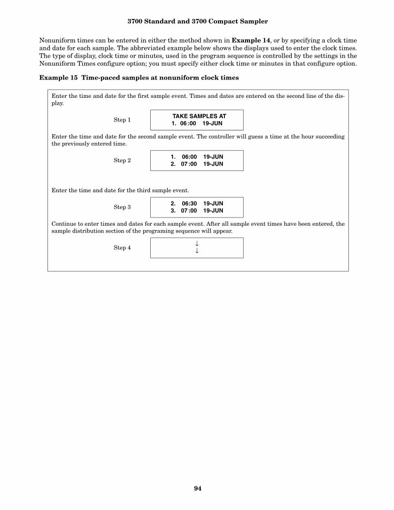
3700 Standard and 3700 Compact Sampler
94
Nonuniform times can be entered in either the method shown in Example 14, or by specifying a clock timeand date for each sample. The abbreviated example below shows the displays used to enter the clock times.The type of display, clock time or minutes, used in the program sequence is controlled by the settings in theNonuniform Times configure option; you must specify either clock time or minutes in that configure option.
Example 15 Time-paced samples at nonuniform clock times
Enter the time and date for the first sample event. Times and dates are entered on the second line of the dis-play.
Step 1TAKE SAMPLES AT 1. 06 :00 19-JUN
Enter the time and date for the second sample event. The controller will guess a time at the hour succeedingthe previously entered time.
Step 21. 06:00 19-JUN2. 07 :00 19-JUN
Enter the time and date for the third sample event.
Step 3 2. 06:30 19-JUN3. 07 :00 19-JUN
Continue to enter times and dates for each sample event. After all sample event times have been entered, thesample distribution section of the programing sequence will appear.
Step 4 ↓↓

3700 Standard and 3700 Compact Sampler
95
Example 16 shows how to program the sampler to take time-paced samples at uniform time intervals of 15minutes starting at 6:00 AM on the following day. One 500 ml sample is to be placed in each bottle. Thesampling is to continue from 6:00 AM until 8:00 AM. The sampling will resume again at 11:00 AM and con-tinue until 1:30 PM. It will pause until 4:00 PM and continue again until 6:00 PM. When the samplingstops at 6:00 PM, fewer than 24 samples may have been taken. Note that the Sampling Stop and Resumesconfigure option has settings that allow you to take a sample at the stop and resume times. See the sectionSampling Stop/Resume.
Example 16 Sampling with stops and resumes.
Press ENTER/PROGRAM to access the interactive state.
Step 1. . . STANDBY . . .
10:34:50 19-JUN-91
Access the program sequence by selecting “PROGRAM.”
Step 2[PROGRAM, CONFIGURE]
SAMPLER
Select “TIME.”
Step 3[TIME, FLOW, STORM]
PACED SAMPLING
Select “UNIFORM.”
Step 4[UNIFORM, NONUNIFORM]
TIME INTERVALS
Enter “0” to set the hours at zero. Press ENTER/PROGRAM to store the number “0” and move to the minutesentry.
Step 5SAMPLE EVERY
0 HOURS, 10 MINUTES
Enter “15” to set the minutes entry to 15.
Step 6SAMPLE EVERY
0 HOURS, 15 MINUTES
Enter “1” to set the number of bottles per sample event to 1.
Step 71 BOTTLES PER
SAMPLE EVENT (1 - 24)
Select “SAMPLES.”
Step 8CHANGE BOTTLES BASEDON [TIME, SAMPLES/BTL]
Enter “1” to set the number of samples per bottle to 1.
Step 9CHANGE BOTTLES EVERY
1 SAMPLES (1 - 8)
Enter “500” to set the sample volume at 500 ml.
Step 10 SAMPLE VOLUMES OF500 ml (10 - 1000)

3700 Standard and 3700 Compact Sampler
96
Select “YES.”
Step 11ENTER START TIME?
[YES, NO]
Enter the start time and date of the sampling program: 6:00 AM tomorrow.
Step 12TAKE FIRST SAMPLE AT
06:00 19-JUN
Enter “5.” There are three stop times and two resume times.
Step 135 STOP or RESUME
TIMES (0-24)
Enter the time and date of the first stop time: 8:00 AM.
Step 14 STOP SAMPLING AT
1.08:0019-JUN
Enter the time and date the program should resume: 11:00 AM.
Step 15 RESUME SAMPLING AT 1.11:0019-JUN
Enter the time and date of the second stop time: 1:30 PM or 13:30. You must enter the times in military time.
Step 16 STOP SAMPLING AT
2.13:3019-JUN
Enter the time and date the program should resume: 4:00 PM or 16:00 in military time.
Step 17 STOP SAMPLING AT
2.13:3019-JUN
Enter the time and date the program should resume: 4:00 PM or 16:00 in military time.
Step 18 STOP SAMPLING AT
3.18:0019-JUN
After this message displays briefly, the sampler will automatically return to the standby state.
Step 19 PROGRAMMING SEQUENCECOMPLETE
Press the START SAMPLING key to run the program.
Step 20. . . STANDBY . . .
10:37:23 19-JUN-91
To start the sampling routine with the first bottle, accept the blinking “1” by pressing the ENTER/PROGRAM key.If you want to start the routine with another bottle, enter the starting bottle number here.
Step 21START SAMPLING BOTTLE 1 (1-24)
This display appears as the sampler counts down the time remaining to the start time. The first line reportsthe bottle which will receive the next sample volume. The second line reports the start time at the left and thecurrent time on the right.
Step 22 BOTTLE 1AT 6:00 10:38:07

3700 Standard and 3700 Compact Sampler
97
When the start time arrives, the sampler will take the first sample. The sample event cycle begins with a pre-sample purge. During the purge, the display indicates the bottle number which will receive the sample volume.
Step 23BOTTLE 1
As soon as the pump runs forward to deliver the sample volume, the message on the second line appears. Thismessage remains through the post-sample purge.
BOTTLE 1PUMPING 500 ml
This display appears when the post-sample purge from the previous sample event is completed. It indicatesthe bottle number which is to receive the sample at the upcoming sample event. The second line displays thescheduled time for the next event on the left. The current time is displayed on the right.
Step 24BOTTLE 2
AT 6:15 8:01:11
The cycle of displays is repeated for each bottle until the sampling routine is done.
Step 25↓↓
When the routine is completed, this message appears. It reports the status of the routine (“DONE”), the totalnumber of sample events, and the current time and date.
Step 26DONE . . . 18 SAMPLES
18:10:35 21-JUN-91

3700 Standard and 3700 Compact Sampler
98
Example 17 illustrates how to program a 24-bottle sampler to allocate six bottles to the first bottle group.The remaining 18 bottles, allocated to the second bottle group, will be used for flow-weighted samples. Thesampler delays the first group 25 minutes after it is enabled.
For the first bottle group, the sampler will take two samples with a 5-minute interval between each sampleevent. At the first sample event, bottles 1 through 3 will each receive 900 ml each (bottles-per-sample mul-tiplexing). At the second timed event, bottles 4 through 6 will receive 900 ml each.
The sampler will fill the second bottle group with flow-paced samples during the same time as the secondbottle group. At each sample event, a single bottle in the second bottle group will receive a 400 ml sample.Each bottle will receive samples from two sample events (samples-per-bottle multiplexing).
Example 17 Storm Sampling.
Press ENTER/PROGRAM to access the interactive state
Step 1. . . STANDBY . . .
10:34:50 12-JUN-92
Access the program sequence by selecting “PROGRAM.”
Step 2[PROGRAM, CONFIGURE]
SAMPLERDisplay 1
Select “STORM.
Step 3[TIME, FLOW, STORM]
PACED SAMPLINGDisplay 12
After displaying this message briefly, the sampler will automatically advance to the next display.
Step 4 TIME MODEFIRST BOTTLE GROUP
Enter “25” to delay the first group sample 25 minutes. (Acceptable range of values: 0 to 999.)
Step 5 25 MINUTE DELAY TOFIRST GROUP SAMPLE
Display 15
Enter “2” to take two timed samples.
Step 6TAKE 2 TIMED
EVENTS ( 1 - 50 )Display 23
Enter “5” to set the time interval between samples to five minutes.
Step 7SAMPLE INTERVALS OF
5 MINUTES (1 - 999)Display 24
Enter the number of bottles per sample event: “3.”
Step 83 BOTTLES PER
SAMPLE EVENT (1-23) Display 30
Enter “1” to place one sample in each bottle.
Step 91 SAMPLES PERBOTTLE (1 - 2)
Display 31
Enter the sample volume of “900” ml.
Step 10SAMPLE VOLUMES OF
900 ml (10 - 1000) Display 50

3700 Standard and 3700 Compact Sampler
99
The sampler will display this message before automatically advancing to the next display.
Step 11 18 BOTTLES, 18000 mlAVAILABLE
Select “FLOW.”
Step 12[TIME, FLOW]
SECOND BOTTLE GROUPDisplay 14
Select “DURING” to fill the second bottle group at the same time as the first bottle group.
Step 13[DURING, AFTER]
TIME MODEDisplay 16
Enter “5” as the flow-pulse interval. The sampler will take a sample every fifth flow pulse.
Step 14SAMPLE EVERY
5 PULSES (1-9999) Display 22
This display requires two entries. Enter “2” hours and “0” to set the maximum amount of time between flow-paced sample events.
Step 15MAX FLOW INTERVAL OF
2 HOURS 0 MINUTESDisplay 110
Enter the number of bottles filled at each sample event: “1.”
Step 161 BOTTLES PER
SAMPLE EVENT (1-22) Display 30
Enter “2” to set the number of samples delivered to each bottle.
Step 172 SAMPLES PERBOTTLE (1 - 50) Display 31
Enter the sample volume of “400” ml.
Step 18SAMPLE VOLUMES OF
400 ml (10 - 990) Display 50
Select “YES” to enter a start time in the following step.
Step 19ENTER START TIME:
[YES, NO]Display 90
This display requires two entries. Enter a time of “06:00” and a date of “20-06” to start the storm routine at6:00 AM on June 20.
Step 20STORM ENABLED AFTER
06:00 20-09Display 93
After displaying this message, the sampler will automatically return to the standby state.
Step 21 PROGRAMMING SEQUENCECOMPLETE . .
This display appears when you press START SAMPLING.
START STORM PROGRAMAT 6:00 5:33:07

3700 Standard and 3700 Compact Sampler
100
Standby StateA sampler in the standby state is waiting for yourinstructions. From standby, you can start orresume a sampling program, access the program orconfigure sequences, take manual samples, anduse the display status key to review program set-tings or the results of a sampling routine.
A sampler in standby uses a number of displays tocommunicate its status. Some of these displays areassociated with the function of a specific key; otherdisplays are used to notify you that a samplingprogram is done, halted, or has encountered aproblem. The standby state displays and valid keysare discussed in the following sections.
Standby Display - When you first turn the sam-pler on, the sampler “wakes up” in the standbystate. The standby display, illustration a, simplyinforms you that the sampler is in standby andreports the current time and date.
At this point, the following keys are operable: ON/OFF, PUMP REVERSE, PUMP FORWARD, START SAM-PLING, ENTER/PROGRAM, MANUAL SAMPLE, NEXTBOTTLE, and DISPLAY STATUS.
Program Halted - A sampling program can behalted with either the STOP or EXIT PROGRAM key; ifthis occurs, the sampler will display the halt mes-sage shown in illustration b. If you halt the programto take a manual sample or to change a setting inthe program or configure sequence, the sampler willreturn to standby. If this is the case, you will not beable to use the RESUME SAMPLING key.
Each operable key is listed and discussed below.
On/off - When in the standby state, this key sim-ply shuts the sampler off.
The displays shown in step 22 alternate as the sampler’s clock approaches the start time. The first line reportsthe bottles which will receive the first sample volumes for each bottle group. The second line reports the starttime at the left and the current time on the right.
Step 22BOTTLE 1
AT 6:25 5:38:07
1 of 2, BOTTLE 3AFTER 5 PULSES
As soon as the pump runs forward to deliver the sample volume, the message on the second line appears. Thismessage remains through the post-sample purge.
Step 23BOTTLE 1
PUMPING 900 ml
The sampler will continue to alternate displays until the routine terminates
Step 24 BOTTLE 2AT 6:30 6:26:1
1 of 2, BOTTLE 3AFTER 5 PULSES
The cycle of displays is repeated for each bottle until the sampling routine is done.
Step 25↓↓
When the routine is completed, this message appears. It reports the status of the routine (“DONE”), the totalnumber of sample events, and the current time and date.
Step 26DONE . . . 42 SAMPLES
18:10:35 25-JUN-92
. . . STANDBY . . .10:37:23 16-JUN-91
a
. . . PROGRAM HALTED . . .10:37:33 19-JUN-91
b

3700 Standard and 3700 Compact Sampler
101
Pump Forward and Pump Reverse - The PUMPFORWARD and PUMP REVERSE keys run the pumpforward or in reverse until you interrupt it withthe STOP key. While the pump is running, the mes-sage shown in c or d displays, depending on thepumping direction.
CAUTION
Tests indicate that the pump produces sound levels inexcess of 85db at one meter. Prolonged exposure tothis sound level could result in hearing loss and re-quires the use of protective ear plugs.
When you press the STOP key, the sampler will dis-play a message similar to the one shown in e. Thismessage indicates the total number of pumpcounts that occurred while the pump was running.This information can be used to set the desirednumber of purge counts required to purge the suc-tion line. See the Purge Counts configure option.Press any key, except STOP and ON/OFF, to return tothe standby display.
Manual Sample - You can take manual samples instandby by pressing the MANUAL SAMPLE key. Afteryou press the MANUAL SAMPLE key, the sampler willdeliver the programmed sample volume to the bot-tle currently under the distributor. A manual sam-ple delivers the sample volume currently entered asa programmed setting, and includes the pre-sampleand post-sample purges. It will also include any pro-grammed rinses and retries. The sampling processcan be stopped with the STOP key at any time. If youpress the MANUAL SAMPLE key while a samplingprogram is in progress, the manual sample will becounted as one of the programmed samples.
While the sample is being delivered, the samplerdisplays a message similar to that illustrated in f.The second line will not appear until the pumpbegins to pump forward to deliver the sample. Thedisplay will revert to standby after the manualsample has been delivered.
Next Bottle - If you want to reposition the distrib-utor, use the NEXT BOTTLE key. The sampler willadvance the distributor to the next bottle position.(The sampler determines the bottle positions byreferring to the Bottle Number configuration set-ting.) The sampler will display the distributor’slocation as illustrated in g. After a short time, thedisplay will revert to standby. If the distributor isover the last bottle position when you press nextbottle, the distributor will move to Bottle 1.
Start Sampling - Once you have programmed andconfigured the sampler, use the START SAMPLINGkey to run the sampling program. The first displayyou’ll see after pressing the START SAMPLING key isillustrated in display h.
If you want to have the sampling program begin witha bottle other than Bottle 1, enter the first bottlenumber here. If “1” is acceptable, press the ENTER/PROGRAM key to place the sampler into the run state.If you do not press a key within 60 seconds, the sam-pler will automatically enter the run state and willbegin the sampling routine with Bottle 1.
There are three instances where the sampler willnot be able to run the program immediately. Theseoccur when the program has been started after: 1)the programmed start time, 2) the first switchtime, and 3) one or more programmed stop times.The sampler responds to these situations as dis-cussed in Examples 18, 19, and 20.
Resume Sampling - To resume or restart the pro-gram, press the RESUME SAMPLING or START SAM-PLING key. When you press RESUME SAMPLING, theprogram will resume at the point it was halted.The display must read “PROGRAM HALTED” forthe resume sampling key to be active. If any sam-ples were missed during the time the program washalted, the sampler will inform you with the mes-sage illustrated in i. The sampler will initiate onesample event if it missed one or more sampleevents.
PUMPING FORWARD . . . c
PUMPING REVERSE . . . d
311 COUNTS FORWARD e
. . . MANUAL SAMPLE . . .PUMPING 200 ml
f
NOW ON BOTTLE 2 g
START SAMPLINGAT BOTTLE 1 (1 - 24) h
2 SAMPLES WILL BESKIPPED
i
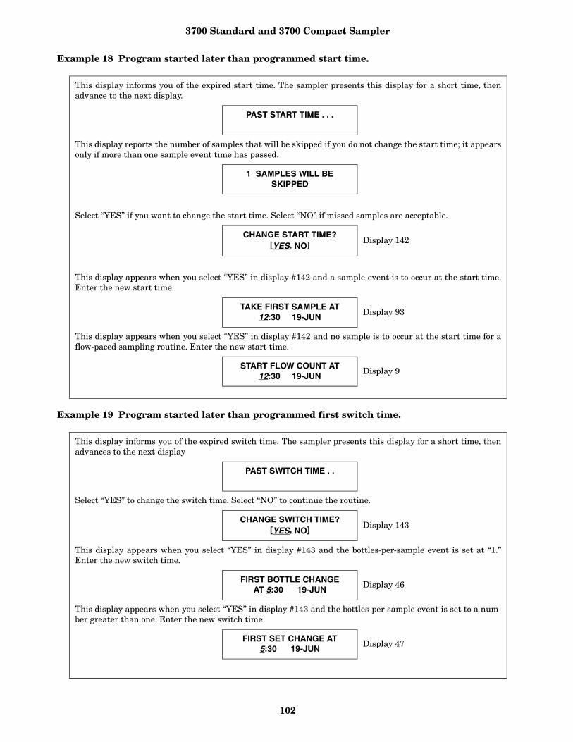
3700 Standard and 3700 Compact Sampler
102
Example 18 Program started later than programmed start time.
Example 19 Program started later than programmed first switch time.
This display informs you of the expired start time. The sampler presents this display for a short time, thenadvance to the next display.
PAST START TIME . . .
This display reports the number of samples that will be skipped if you do not change the start time; it appearsonly if more than one sample event time has passed.
1 SAMPLES WILL BESKIPPED
Select “YES” if you want to change the start time. Select “NO” if missed samples are acceptable.
CHANGE START TIME?[YES, NO] Display 142
This display appears when you select “YES” in display #142 and a sample event is to occur at the start time.Enter the new start time.
TAKE FIRST SAMPLE AT12:30 19-JUN
Display 93
This display appears when you select “YES” in display #142 and no sample is to occur at the start time for aflow-paced sampling routine. Enter the new start time.
START FLOW COUNT AT12:30 19-JUN
Display 9
This display informs you of the expired switch time. The sampler presents this display for a short time, thenadvances to the next display
PAST SWITCH TIME . .
Select “YES” to change the switch time. Select “NO” to continue the routine.
CHANGE SWITCH TIME?[YES, NO] Display 143
This display appears when you select “YES” in display #143 and the bottles-per-sample event is set at “1.”Enter the new switch time.
FIRST BOTTLE CHANGEAT 5:30 19-JUN
Display 46
This display appears when you select “YES” in display #143 and the bottles-per-sample event is set to a num-ber greater than one. Enter the new switch time
FIRST SET CHANGE AT5:30 19-JUN
Display 47
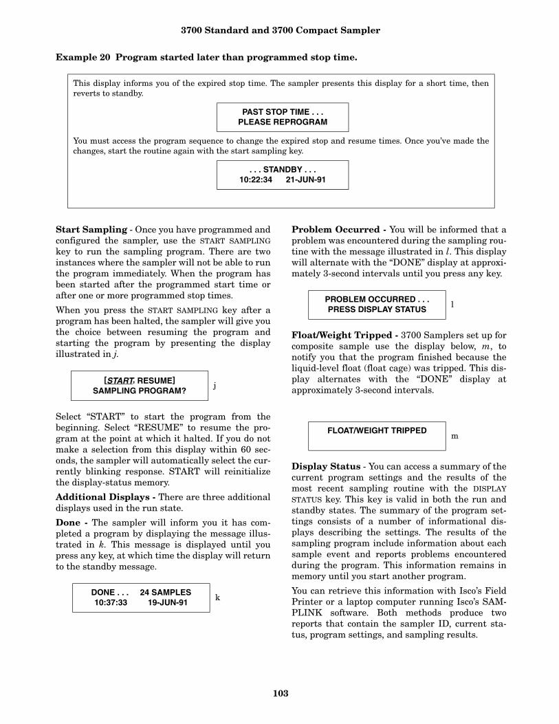
3700 Standard and 3700 Compact Sampler
103
Example 20 Program started later than programmed stop time.
Start Sampling - Once you have programmed andconfigured the sampler, use the START SAMPLINGkey to run the sampling program. There are twoinstances where the sampler will not be able to runthe program immediately. When the program hasbeen started after the programmed start time orafter one or more programmed stop times.
When you press the START SAMPLING key after aprogram has been halted, the sampler will give youthe choice between resuming the program andstarting the program by presenting the displayillustrated in j.
Select “START” to start the program from thebeginning. Select “RESUME” to resume the pro-gram at the point at which it halted. If you do notmake a selection from this display within 60 sec-onds, the sampler will automatically select the cur-rently blinking response. START will reinitializethe display-status memory.
Additional Displays - There are three additionaldisplays used in the run state.
Done - The sampler will inform you it has com-pleted a program by displaying the message illus-trated in k. This message is displayed until youpress any key, at which time the display will returnto the standby message.
Problem Occurred - You will be informed that aproblem was encountered during the sampling rou-tine with the message illustrated in l. This displaywill alternate with the “DONE” display at approxi-mately 3-second intervals until you press any key.
Float/Weight Tripped - 3700 Samplers set up forcomposite sample use the display below, m, tonotify you that the program finished because theliquid-level float (float cage) was tripped. This dis-play alternates with the “DONE” display atapproximately 3-second intervals.
Display Status - You can access a summary of thecurrent program settings and the results of themost recent sampling routine with the DISPLAYSTATUS key. This key is valid in both the run andstandby states. The summary of the program set-tings consists of a number of informational dis-plays describing the settings. The results of thesampling program include information about eachsample event and reports problems encounteredduring the program. This information remains inmemory until you start another program.
You can retrieve this information with Isco’s FieldPrinter or a laptop computer running Isco’s SAM-PLINK software. Both methods produce tworeports that contain the sampler ID, current sta-tus, program settings, and sampling results.
This display informs you of the expired stop time. The sampler presents this display for a short time, thenreverts to standby.
PAST STOP TIME . . .PLEASE REPROGRAM
You must access the program sequence to change the expired stop and resume times. Once you’ve made thechanges, start the routine again with the start sampling key.
. . . STANDBY . . .10:22:34 21-JUN-91
[START, RESUME]SAMPLING PROGRAM?
j
DONE . . . 24 SAMPLES10:37:33 19-JUN-91
k
PROBLEM OCCURRED . . .PRESS DISPLAY STATUS
l
FLOAT/WEIGHT TRIPPEDm

3700 Standard and 3700 Compact Sampler
104
If a sampling routine is in progress when you pressthe DISPLAY STATUS key, the sampling routine willbe suspended. No samples will be taken until youexit Display Status.
If the pump count reaches the number entered forthe Tubing Life Warning setting, the Pump TubingWarning will be displayed. An illustration of thewarning is shown below.
Display StatusThe sampler tracks and reports the followingitems:
• program start time and date; • sample volume;• source of each sample event; • cause of any missed samples;• start time of each sample event;• number of pump counts to liquid detection for
each event;• time the routine was completed;• sampler ID;• current time and date;• program settings.
Each of these items is illustrated in Example 21.
When you press DISPLAY STATUS, the display shownbelow follows the pump tubing warning. It allowsyou to review the program settings or samplingresults.
Review - Select “REVIEW” to review the programsettings and sampling results. The sampler willpresent the display shown below. Use this displayto leave the Display Status procedure or to reviewthe program settings or sampling results.
No - Select “NO” to return to the previous operat-ing state. If you entered Display Status fromstandby, the standby message will reappear. If youentered Display Status from the run state, thesampling routine will resume.
Settings - Select “SETTINGS” to review the pro-gram settings. Use the left arrow, right arrow, andthe enter/program keys to move through the sam-pling settings. When the right arrow or the enter/program key is pressed at the last settings display,the “REVIEW PROGRAM” display will reappear.
Results - Select “RESULTS” to review the resultsof the sampling routine. The first display reportsthe time and date the sampling program started.Use the left and right arrows, and enter/programkeys to move through the results. If the routinewas finished at the time you pressed the displaystatus key, the last display will report the time anddate the routine ended.
Print - Select “PRINT” from Display #148 to sendthe current status, program settings, or samplingresults to the Isco Field Printer. For information onthe reports produced by the Field Printer, refer tothe Field Printer Instruction Manual.
When you select “PRINT,” Display #149 appears.Use this display to select the settings or resultsreport. (The sampler will interrupt the reports totake a sample, if necessary.) Select “NO” to returnto standby.
The sampler will display one of two messages as itsends the data to the printer. The first messageinforms you that the transmission is in progress.The second message is a warning informing youthat the sampler is unable to detect the printer. Ifyou see the warning message, check the cable con-nections between the printer and the sampler.
WARNING: Replacepump tubing!
[REVIEW, PRINT] PROGRAM INFORMATION
Display #148
REVIEW PROGRAM [NO,SETTINGS, RESULTS]
Display #150
PRINT PROGRAM [NO,SETTINGS, RESULTS]
Display #149
. . . PRINTING . . .PROGRAM INFORMATION
PRINT ABORTEDNO PRINTER DETECTED!
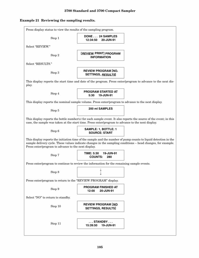
3700 Standard and 3700 Compact Sampler
105
Example 21 Reviewing the sampling results.
Press display status to view the results of the sampling program.
Step 1DONE . . . 24 SAMPLES12:34:50 20-JUN-91
Select “REVIEW.”
Step 2[REVIEW, PRINT] PROGRAM
INFORMATION
Select “RESULTS.”
Step 3REVIEW PROGRAM [NO,
SETTINGS, RESULTS]
This display reports the start time and date of the program. Press enter/program to advance to the next dis-play.
Step 4 PROGRAM STARTED AT5:30 19-JUN-91
This display reports the nominal sample volume. Press enter/program to advance to the next display.
Step 5200 ml SAMPLES
This display reports the bottle number(s) for each sample event. It also reports the source of the event; in thiscase, the sample was taken at the start time. Press enter/program to advance to the next display.
Step 6SAMPLE: 1, BOTTLE: 1
SOURCE: START
This display reports the initiation time of the sample and the number of pump counts to liquid detection in thesample delivery cycle. These values indicate changes in the sampling conditions – head changes, for example.Press enter/program to advance to the next display.
Step 7TIME: 5:30 19-JUN-91
COUNTS: 280
Press enter/program to continue to review the information for the remaining sample events.
Step 8 ↓↓
Press enter/program to return to the “REVIEW PROGRAM” display.
Step 9PROGRAM FINISHED AT
12:00 20-JUN-91
Select “NO” to return to standby.
Step 10 REVIEW PROGRAM [NO,SETTINGS, RESULTS]
Step 11. . . STANDBY . . .
15:39:50 19-JUN-91
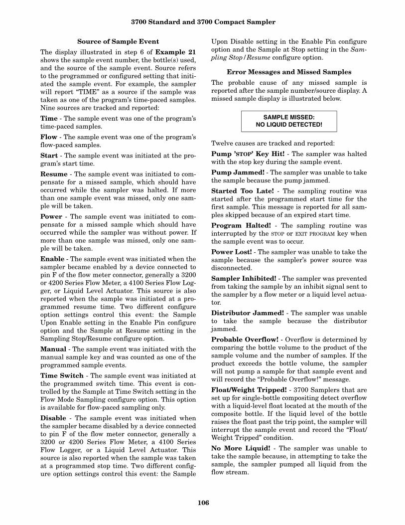
3700 Standard and 3700 Compact Sampler
106
Source of Sample Event
The display illustrated in step 6 of Example 21shows the sample event number, the bottle(s) used,and the source of the sample event. Source refersto the programmed or configured setting that initi-ated the sample event. For example, the samplerwill report “TIME” as a source if the sample wastaken as one of the program’s time-paced samples.Nine sources are tracked and reported:
Time - The sample event was one of the program’stime-paced samples.
Flow - The sample event was one of the program’sflow-paced samples.
Start - The sample event was initiated at the pro-gram’s start time.
Resume - The sample event was initiated to com-pensate for a missed sample, which should haveoccurred while the sampler was halted. If morethan one sample event was missed, only one sam-ple will be taken.
Power - The sample event was initiated to com-pensate for a missed sample which should haveoccurred while the sampler was without power. Ifmore than one sample was missed, only one sam-ple will be taken.
Enable - The sample event was initiated when thesampler became enabled by a device connected topin F of the flow meter connector, generally a 3200or 4200 Series Flow Meter, a 4100 Series Flow Log-ger, or Liquid Level Actuator. This source is alsoreported when the sample was initiated at a pro-grammed resume time. Two different configureoption settings control this event: the SampleUpon Enable setting in the Enable Pin configureoption and the Sample at Resume setting in theSampling Stop/Resume configure option.
Manual - The sample event was initiated with themanual sample key and was counted as one of theprogrammed sample events.
Time Switch - The sample event was initiated atthe programmed switch time. This event is con-trolled by the Sample at Time Switch setting in theFlow Mode Sampling configure option. This optionis available for flow-paced sampling only.
Disable - The sample event was initiated whenthe sampler became disabled by a device connectedto pin F of the flow meter connector, generally a3200 or 4200 Series Flow Meter, a 4100 SeriesFlow Logger, or a Liquid Level Actuator. Thissource is also reported when the sample was takenat a programmed stop time. Two different config-ure option settings control this event: the Sample
Upon Disable setting in the Enable Pin configureoption and the Sample at Stop setting in the Sam-pling Stop/Resume configure option.
Error Messages and Missed Samples
The probable cause of any missed sample isreported after the sample number/source display. Amissed sample display is illustrated below.
Twelve causes are tracked and reported:
Pump ’STOP’ Key Hit! - The sampler was haltedwith the stop key during the sample event.
Pump Jammed! - The sampler was unable to takethe sample because the pump jammed.
Started Too Late! - The sampling routine wasstarted after the programmed start time for thefirst sample. This message is reported for all sam-ples skipped because of an expired start time.
Program Halted! - The sampling routine wasinterrupted by the STOP or EXIT PROGRAM key whenthe sample event was to occur.
Power Lost! - The sampler was unable to take thesample because the sampler’s power source wasdisconnected.
Sampler Inhibited! - The sampler was preventedfrom taking the sample by an inhibit signal sent tothe sampler by a flow meter or a liquid level actua-tor.
Distributor Jammed! - The sampler was unableto take the sample because the distributorjammed.
Probable Overflow! - Overflow is determined bycomparing the bottle volume to the product of thesample volume and the number of samples. If theproduct exceeds the bottle volume, the samplerwill not pump a sample for that sample event andwill record the “Probable Overflow!” message.
Float/Weight Tripped! - 3700 Samplers that areset up for single-bottle compositing detect overflowwith a liquid-level float located at the mouth of thecomposite bottle. If the liquid level of the bottleraises the float past the trip point, the sampler willinterrupt the sample event and record the “Float/Weight Tripped” condition.
No More Liquid! - The sampler was unable totake the sample because, in attempting to take thesample, the sampler pumped all liquid from theflow stream.
SAMPLE MISSED:NO LIQUID DETECTED!

3700 Standard and 3700 Compact Sampler
107
No Liquid Detected! - The sampler was unableto take the sample because no liquid was detected.
Sampler Shut 'Off'! - The sampler was unable totake the sample because it was halted with the ON/OFF key during the sample event.
Run StateA sampler in the run state is executing the sam-pler’s instructions according to the settings you’veentered in the program and configure sequences.
To start a sampling program and place the samplerinto the run state, press the start sampling key.While running the sampling program, the samplerwill present several displays that allow you tomonitor the sampler’s progress. The displays arelisted with a brief explanation in Examples 22,23, and 24.
If you encounter a problem while running a sam-pling routine that results in missed samples, an
asterisk will appear in the lower right corner of thedisplay, as illustrated below.
There is one condition under which the samplerwill enter the run state after the start samplingkey is pressed, but will not begin the sampling pro-gram. If the sampler is interfaced with a flowmeter, liquid level actuator, or other equipmentcapable of transmitting an inhibit signal, the sam-pler will not begin the program until the inhibitsignal is suspended. The sampler will use the fol-lowing display to inform you that the sampler isinhibited.
Example 22 Run State Displays – Time-paced sampling.
BOTTLE 11AT 6:00 5:42:33 *
SAMPLER INHIBITED!10:32 19-JUN
Sampler Inhibited Display
Indicates the bottle number of the next sequential sample. The second line reports the scheduled sampleevent time followed by the current time.
Display 1BOTTLE 5
AT 5:44 5:42:33
Indicates the scheduled time and receiving bottle numbers for an upcoming sample event. The sampling pro-gram requires four bottles per sample event.
Display 2BOTTLES 1- 4
AT 6:00 5:55:33
Indicates the number of the upcoming sample, the total number of samples each bottle is to receive, and thecurrent bottle number. The program requires four samples per bottle.
Display 31 OF 4, BOTTLE 1AT 6:00 5:55:33
Indicates the sample and bottle numbers of the next sample event. The bottle set consists of four bottles. Thesampling program requires that four samples be placed in each bottle of the set.
Display 41 OF 4, BTLS 1- 4AT 6:00 5:55:33
Indicates the sample and bottle number of the next sample event. The current time appears in the lower rightcorner. The sampling program requires that you use one bottle per sample event and that you switch the bot-tles on a time basis. This display alternates with the display illustrated in item 6 at 3-second intervals.
Display 5 SAMPLE 3, BOTTLE 1AT 6:00 5:42:33
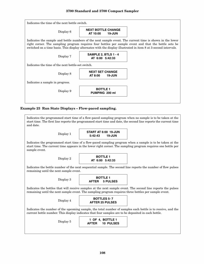
3700 Standard and 3700 Compact Sampler
108
Example 23 Run State Displays – Flow-paced sampling.
Indicates the time of the next bottle switch.
Display 6 NEXT BOTTLE CHANGE AT 10:00 19-JUN
Indicates the sample and bottle numbers of the next sample event. The current time is shown in the lowerright corner. The sampling program requires four bottles per sample event and that the bottle sets beswitched on a time basis. This display alternates with the display illustrated in item 8 at 3-second intervals.
Display 7SAMPLE 2, BTLS 1 - 4
AT 6:00 5:42:33
Indicates the time of the next bottle-set switch.
Display 8 NEXT SET CHANGE AT 8:00 19-JUN
Indicates a sample in progress.
Display 9BOTTLE 1
PUMPING 200 ml
Indicates the programmed start time of a flow-paced sampling program when no sample is to be taken at thestart time. The first line reports the programmed start time and date, the second line reports the current timeand date.
Display 1START AT 6:00 19-JUN
5:42:43 19-JUN
Indicates the programmed start time of a flow-paced sampling program when a sample is to be taken at thestart time. The current time appears in the lower right corner. The sampling program requires one bottle persample event.
Display 2 BOTTLE 1AT 6:00 5:42:33
Indicates the bottle number of the next sequential sample. The second line reports the number of flow pulsesremaining until the next sample event.
Display 3 BOTTLE 1AFTER 5 PULSES
Indicates the bottles that will receive samples at the next sample event. The second line reports the pulsesremaining until the next sample event. The sampling program requires three bottles per sample event.
Display 4 BOTTLES 5- 7AFTER 25 PULSES
Indicates the number of the upcoming sample, the total number of samples each bottle is to receive, and thecurrent bottle number. This display indicates that four samples are to be deposited in each bottle.
Display 5 1 OF 4, BOTTLE 1AFTER 10 PULSES

3700 Standard and 3700 Compact Sampler
109
Example 24 Run State Displays – Composite sampling.
Indicates the sample and bottle numbers of the next sample event. The bottle set consists of four bottles. Thesampling program requires that four samples be placed in each bottle of the set.
Display 61 OF 4, BTLS 1- 4
AFTER 1000 PULSES
Indicates the sample and bottle number of the next sample event. The sampling program requires that youuse one bottle per sample event and that you switch the bottles on a time basis. Alternates with the displayillustrated in item 8 at 3-second intervals.
Display 7SAMPLE 2, BOTTLE 1
AFTER 10 PULSES
Indicates the time of the next bottle switch.
Display 8NEXT BOTTLE CHANGE
AT 10:00 19-JUN
Indicates the time of the next bottle switch.
Display 9 SAMPLE 2, BTLS 1 - 4AFTER 10 PULSES
Indicates the time of the next bottle-set switch.
Display 10NEXT SET CHANGE AT 10:00 19-JUN
Indicates a sample in progress.
Display 11BOTTLE 1
PUMPING 200 ml
Indicates the sample number of the next sample and the total number of samples for time-paced routines. Thecurrent time is shown in the lower right corner.
Display 1 SAMPLE 1 OF 12AT 6:00 5:43:33
Indicates the sample number of the next sample and the total number of samples for flow-paced routines.
Display 2SAMPLE 1 OF 12
AFTER 10 PULSES
Indicates a sample in progress.
Display 3BOTTLE 1
PUMPING 200 ml
3700 Standard and 3700 Compact Sampler
110
Chapter 5 Options and Interfacing Equipment
IntroductionThis chapter discusses major options availablewith the Isco 3700 Standard and Compact Sam-plers. Included is information about:
• Conversion for composite sampling;• Programming and configuring the controller
for composite sampling;• Connection to Isco and non-Isco flow meters; • Interface devices;• Master/Slave operation;• Use with the Model 1640 Liquid Level Actuator;• Use with the Model 583 Field Computer.
Conversion for Composite Sampling - The3700 Standard and Compact Samplers are fullyprogrammable for time-paced and flow-paced com-posite sampling. The object of composite samplingis to collect a series of discrete, equal-volume sam-ples at known time or flow intervals, and to placethese samples into a single composite sample con-tainer.
Conversion Procedure - To prepare your 3700Standard for composite sampling, you must con-vert the center section. To do so, remove the dis-tributor arm assembly, install a shorter pumptube, and install the optional composite shut-offfloat cage assembly. With the portable, completethe preparation by the adding a composite samplecontainer and locating ring in the standard bottlebase or an optional composite base. With the com-pact, remove the inner sleeve and install theproper bottle configuration for composite sampling.
These are the listed steps needed to convert the3700:
1. Separate the center section from the remainderof the sampler.
2. Remove the pump tube and distributor armfrom the sampler, as described in Removing thePump Tube (Chapter 6).
3. Turn the center section over, as shown in Fig-ure 26, and install the optional float and floatcage. You should install the shaft on the “diving-bell” float in the hole in the distributor shaft, asshown. Attach the float cage to the underside ofthe center section using the four screws and the1-inch spacers provided with the float-cage kit. When attaching the cage, reuse the existing lock-washers.Be sure the float cage is oriented with
the tube guide positioned as shown in Figure 20.The float and float cage direct the discharge ofthe sample into the composite container and pro-vide a fail-safe shut-off to prevent accidental overfilling of the composite container.
4. Feed the 34.5-inch (88.5-cm) composite-pumptube (supplied with the optional float and floatcage) through the port in the center section.Then, place it in the float-cage tube guide, asshown in Figure 26, and install it in the pumpas described in Installing a New Pump Tube(Chapter 6).
Standard Sample Bottle TubYou can collect composite samples in the 3700Standard’s sample bottle base equipped witheither a 2.5-gallon glass or polyethylene plasticcontainer (or by inserting either type of containerin the 3700 Compact’s base).
These containers are available as options for thesamplers. If you intend to use the 2.5-gallon com-posite sample containers in the standard sample-bottle tub, you must have the standard base com-posite bottle locating deck with the 3700 Standard.
Installing the Deck in the 3700 Standard -Prepare the standard bottle base by first removingthe retaining ring and sample bottles. Then, placethe locating deck, open side down, in the bottom ofthe sample bottle tub. The locating deck has tworecessed areas: the deeper recess locates the glasscontainer, the shallower recess locates the plasticbottle. Finally, place the desired sample containeron the locating deck and re-assemble the sampler.
Optional Composite TubThe 3700 Standard has two sizes of composite con-tainers: 2.5-gallon and 4-gallon. The 2.5-galloncontainers are used with the sequential bottle baseand a locating ring. The 4-gallon wide-mouth com-posite container requires the optional compositetub. Like the standard tub, the composite base hasdouble-walled construction with polyurethanefoam insulation.

3700 Standard and 3700 Compact Sampler
111
Figure 26 Composite Sampling: Standard Bottle Tub
Prepare the tub for composite sampling by install-ing the sample container. No locating deck isrequired for the composite tub: locating depres-sions are integrally molded into the tub. You canthen attach the composite base to the center sec-tion. Note: When cooling the samples with ice, themelt water may cause the bottle to float when youremove the center section.
Programming and Configuring the Controller for Composite Sampling
After converting the sampler, be sure to change thebottle number and size settings in the Bottles andSizes configure option. (Refer to Event Mark andBottle Signal Output.) You must reprogram thecontroller for composite sampling because chang-ing the bottle setting will change the programsequence. Refer to Programming Introduction forinformation on programming the controller.
Connections to External DevicesThe 3700 Series Samplers can collect samples on aflow-proportional basis using flow inputs from anexternal flow meter. The 3700 requires a 5-to-15VDC pulse of at least 25-millisecond duration toregister a flow pulse. Flow meters are connected tothe sampler by attaching a flow meter connectcable to the flow meter connector located on therear of the sampler.
Your sampler has an additional connector, labeled“PRINTER,” used to connect the sampler to an IscoField Printer, Isco Field Computer, or laptop com-puter. (Note: Both the flow meter connector andthe printer connector use the same 6-pin configu-ration.) The printer cable connector accepts boththe connector from the field printer and a cablefrom a field computer or a laptop computer run-ning the SAMPLINK software.
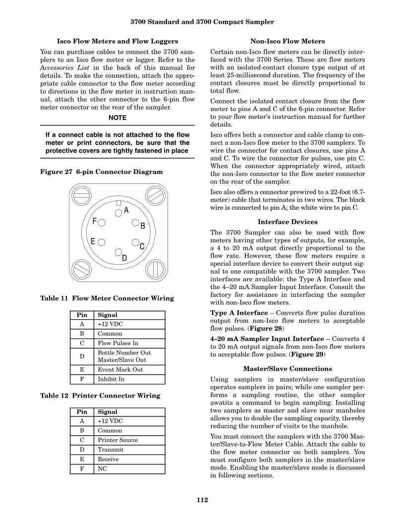
3700 Standard and 3700 Compact Sampler
112
Isco Flow Meters and Flow Loggers
You can purchase cables to connect the 3700 sam-plers to an Isco flow meter or logger. Refer to theAccessories List in the back of this manual fordetails. To make the connection, attach the appro-priate cable connector to the flow meter accordingto directions in the flow meter in instruction man-ual, attach the other connector to the 6-pin flowmeter connector on the rear of the sampler.
NOTE
If a connect cable is not attached to the flowmeter or print connectors, be sure that theprotective covers are tightly fastened in place
Figure 27 6-pin Connector Diagram
Table 11 Flow Meter Connector Wiring
Table 12 Printer Connector Wiring
Non-Isco Flow Meters
Certain non-Isco flow meters can be directly inter-faced with the 3700 Series. These are flow meterswith an isolated-contact closure type output of atleast 25-millisecond duration. The frequency of thecontact closures must be directly proportional tototal flow.
Connect the isolated contact closure from the flowmeter to pins A and C of the 6-pin connector. Referto your flow meter’s instruction manual for furtherdetails.
Isco offers both a connector and cable clamp to con-nect a non-Isco flow meter to the 3700 samplers. Towire the connector for contact closures, use pins Aand C. To wire the connector for pulses, use pin C.When the connector appropriately wired, attachthe non-Isco connector to the flow meter connectoron the rear of the sampler.
Isco also offers a connector prewired to a 22-foot (6.7-meter) cable that terminates in two wires. The blackwire is connected to pin A; the white wire to pin C.
Interface Devices
The 3700 Sampler can also be used with flowmeters having other types of outputs, for example,a 4 to 20 mA output directly proportional to theflow rate. However, these flow meters require aspecial interface device to convert their output sig-nal to one compatible with the 3700 sampler. Twointerfaces are available: the Type A Interface andthe 4–20 mA Sampler Input Interface. Consult thefactory for assistance in interfacing the samplerwith non-Isco flow meters.
Type A Interface – Converts flow pulse durationoutput from non-Isco flow meters to acceptableflow pulses. (Figure 28)
4–20 mA Sampler Input Interface – Converts 4to 20 mA output signals from non-Isco flow metersto acceptable flow pulses. (Figure 29)
Master/Slave Connections
Using samplers in master/slave configurationoperates samplers in pairs; while one sampler per-forms a sampling routine, the other samplerawatits a command to begin sampling. Installingtwo samplers as master and slave near manholesallows you to double the sampling capacity, therebyreducing the number of visits to the manhole.
You must connect the samplers with the 3700 Mas-ter/Slave-to-Flow Meter Cable. Attach the cable tothe flow meter connector on both samplers. Youmust configure both samplers in the master/slavemode. Enabling the master/slave mode is discussedin following sections.
Pin SignalA +12 VDC
B Common
C Flow Pulses In
DBottle Number OutMaster/Slave Out
E Event Mark Out
F Inhibit In
Pin SignalA +12 VDC
B Common
C Printer Source
D Transmit
E Receive
F NC
A
B
CD
E
F
3700 Standard and 3700 Compact Sampler
113
While the master sampler is performing a sam-pling routine, it sends an inhibit signal out on pinD. The slave sampler, receiving the signal on pin F,remains dormant until the master sampler com-pletes its routine. At this point, the samplerreverses roles. The master/slave inhibit signal out-put and the bottle number output for event marksboth use pin D. When two samplers are connectedas master and slave, the master/slave inhibit sig-nal replaces the bottle number output.
When the master/slave pair connects to a flowmeter with the Master/Slave to Flow Meter Cable,the inhibit signal will be sent to both the slavesampler and the flow meter. Since this signal doesnot vary as it would if it were a bottle number sig-nal, the flow meter will not report a bottle numberat the event mark.
Master/Slave Cycle – When installing the master/slave pair, you must press the START SAMPLINGkey on both machines to place both machines in therun state. The first machine started becomes themaster. After the master completes its routine, youcan service it and start it again.
After servicing, if you don’t start the sampler again,the master/slave cycle will halt after the secondsampler finishes its routine. The sampler cannotreverse roles unless both are in the run state.
Continuous Master/Slave Sampling vs. StormMonitoring with Master/Slave Pairs – You canuse master/slave sampling in applications whereyou want to sample continuously or for stormwater runoff monitoring. In continuous samplingapplications, service each sampler when it termi-nates its routine. After servicing, press the STARTSAMPLING key to start the sampler again andresume the master/slave cycle. The samplers cancycle continuously because each has the same role -and usually identical sampling routines. If you usea master/slave pair with a flow meter, the flowmeter usually provides pacing controls rather thansampler enable controls.
However, storm water runoff monitoring is a non-continuous, event-driven application requiring adifferent servicing cycle. In many storm monitor-ing applications, the master/slave pair and a flowmeter make up a monitoring system activated by astorm event. The flow meter provides samplerenable controls triggered by a storm event. Afterthe storm event and the master/slave pair havecompleted their routines, you must service andrestart the entire system. Not only must you ser-vice the samplers, but you must reset the flowmeter sampler enable control to detect anotherstorm event. You will find instructions for install-
ing and starting a master/slave pair in a stormmonitoring application in the STORM SamplingCheck List. For information on installing andresetting a system, see the Isco Storm Water Run-off Monitoring Pocket Guide.
Model 1640 Liquid Level Actuator
The Liquid Level Actuator is an accessory thatbegins a sampling routine when the liquid level ofthe flow stream reaches a predetermined height.The actuator inhibits sampling according to flowlevels; that is if the level of the flow stream fallsbelow the actuator’s probe, the actuator will inhibitsampling until the level again rises to contact theprobe.
You can set the actuator to control the sampler intwo modes.
• Latch Mode: The sampler continues the sam-pling routine even though the liquid level hasreceded and liquid no longer contacts the sen-sor.
• Toggle Mode: The sampler will halt the routinewhen the liquid ceases to contact the sensor.
To connect the actuator to the sampler, attach theactuator cable to the flow meter connector on therear of the sampler. Refer to the Liquid Level Actu-ator Instruction Manual provided with the actua-tor for additional information. You can use theactuator with an Isco flow meter if you have the Y-Connect Cable.
You must configure the sampler to respond to theactuator. Information configuring the sampler foruse with the actuator can be found in the discus-sion of the Enable Pin configure option section inChapter 4.
Model 583 Field Computer
The Model 583 Field Computer is a small, durablefield interrogator that collects data from Isco’s3700 Series Samplers, and 3200 Series FlowMeters. It creates data files that are identical tothose used by the FLOWLINK software. The 583Field Computer is no longer available from Isco.
The 583 is bundled with two software programs.FIELDCOM resides in the 583’s memory andretrieves stored data from the flow meter or sam-pler, and converts sampler data into ASCII textfiles and flow meter data into FLOWLINK-compat-ible data files called “data sets.” XFER583 runs ona desktop IBM PC-compatible and can run as astand-alone program to transfer sampler text filesdirectly to the computer or as a FLOWLINK mod-ule that transfers data files to FLOWLINK datadirectories.

3700 Standard and 3700 Compact Sampler
114
For more information about the 583 and its soft-ware program, see the manual for the Model 583Field Computer and the FIELDCOM andXFER583 User’s Manual.
Figure 28 Type A Interface
Figure 29 4-20 mA Sampler Input Interface
3700 Standard and 3700 Compact Sampler
115
Chapter 6 Routine MaintenanceIntroduction
This chapter covers routine maintenance of the3700 Portable Samplers. It includes the followingsections:
• Cleaning the sampler case, tubing, and samplebottles;
• Cleaning protocols for priority pollutants;• Replacement of pump tubing;• Replacement of suction tubing;• Changing the internal desiccant.
Cleaning the SamplerThe following sections contain instructions forcleaning the sampler case, tubing, and bottles.Cleaning protocols for priority pollutants aregiven. Disassemble the sampler for cleaning by fol-lowing the instructions found in Assembly and Dis-assembly of the Case in Chapter 2.
Case – You can clean the top cover and sample bot-tle base with warm soapy water or by sprayingthem with a hose. You can clean the center sectionin a similar manner if a power source is attachedto the 12 VDC connector and the flow meter con-nector is tightly capped.
Tubing – The suction line and pump tubing canbe cleaned by placing the end of the suction line ina cleaning solution and pumping this solutionthrough the tubing system using the pump for-ward and pump reverse keys. Follow with a cleanwater rinse.
Sample Bottles – The glass sample bottles have awide mouth to facilitate cleaning. You can be washthem with a brush and soapy water, in a dish-washer, or in an autoclave. (Do not autoclave theplastic lids.) The 1000 ml polypropylene plasticwedge-shaped sample bottles also have a widemouth and are formed so that they have no inac-cessible corners. You can wash plastic bottles in adishwasher but do not autoclave them.
Cleaning Protocols for Priority Pollutants
The following sections are taken from U.S. Environ-mental Protection Agency Publications EPA-600/4-77-039 (“Sampling of Water and Wastewater” by Dr.Phillip E. Shelley) for an example of sampler clean-ing procedures for priority pollutants.
Proper Cleaning - The proper cleaning of equip-ment used in the sampling of water and wastewa-
ter is essential to ensuring valid results fromlaboratory analysis. Cleaning protocols should bedeveloped for all sampling equipment early in thedesign of the wastewater characterization pro-gram. The laboratory analyst should be consulted,both to ensure that the procedures and techniquesare adequate, as well as to avoid including prac-tices that are not warranted in view of the analysisto be performed.
Cleaning Examples – As an example, Lair (1974)has set down the standard operating proceduresfor the cleaning of sample bottles and field proce-dures equipment used by USEPA Region IV Sur-veillance and Analysis field personnel engaged inNPDES compliance monitoring. They are repro-duced below for a typical automatic sampler andrelated sampling equipment.
Isco Glass Sample Bottles:
1. One spectro-grade acetone rinse.2. Dishwasher cycle (wash and tap water rinse, no
detergent).3. Acid wash with at least 20% hydrochloric acid.4. Dishwasher cycle, tap and distilled water rinse
cycles, no detergent.5. Replace in covered Isco bases.
Suction Line (1/4 or 3/8 Vinyl):
1. Do not reuse sample tubing. No cleaningrequired. Use new sample tubing for each newsampling setup.
2. Use Teflon tubing where samples for organicsare to be collected.
Isco Pump Tube:
1. Rinse by pumping hot tap water through tubingfor at least 2 minutes.
2. Acid wash tubing by pumping at least a 20%solution of hydrochloric acid through tubing forat least 2 minutes.
3. Rinse by pumping hot tap water through tubingfor at least 2 minutes.
4. Rinse by pumping distilled water through tub-ing for at least 2 minutes.
Teflon Tubing:
1. Rinse twice with spectro-grade acetone.2. Rinse thoroughly with hot tap water using a
brush if possible to remove particulate matterand surface film.
3. Rinse thoroughly three times with tap water.
3700 Standard and 3700 Compact Sampler
116
4. Acid wash with at least 20 percent hydrochloricacid.
5. Rinse thoroughly three times with tap water.6. Rinse thoroughly three times with distilled
water.7. Rinse thoroughly with petroleum ether and dry
by pulling room air through tubing.
8. Dry overnight in warm oven (less than 150o F) ifpossible.
9. Cap ends with aluminum foil.
Replacement of Pump TubingThe pump tube serves two functions: it is a pumptube in the peristaltic pump and a distributiontube, routing the sample liquid from the pump out-let to the sample bottle.
The pump tube consists of a single 42-inch (103.8cm) piece of medical-grade Silastic silicone rubbertubing. Isco uses medical-grade tubing because ofits superior mechanical properties and because itdoes not contain any organic materials. Nonmedi-cal-grade silicone rubber tubing can containorganic vulcanizing agents. During vulcanizing,these agents are converted into compounds whichcan leach into the sample. The medical-grade sili-cone tubing Isco supplies for use with the 3700Sampler will not contribute any organic materialto the sample.
CAUTIONBe sure the power is disconnected from the unitbefore you exchange the pump tubing. The pumpis extremely powerful. If the sampler activatesthe pump while you are manipulating the tubingwithin the pump, you may be seriously injured.
Inspection of Pump Tubing - The pump tubingis extremely durable. However, the constantmechanical strain placed on the tubing by the peri-staltic action of the pump eventually causes thetubing to fatigue and fail. Remove the cover period-ically to inspect the pump tubing for wear insidethe pump. Check the tubing for cracks where thepump roller compresses the tubing. Replace theworn out pump tubing with a new pump tube, ifnecessary.
The inspections should be fairly frequent when theliquid being sampled contains a high percentage ofsuspended solids. If the liquid is relatively free of sol-ids, the inspections can be less frequent. The TubingLife configure option reports the number of pumpcounts elapsed during the life of the pump tube.
The amount of tubing (13.5 inches) used in thepump is less than half of the total length of the
pump tube (42 inches). In some cases, when thetube has not been damaged to the point of leaking,the tube can be used twice by simply turning itaround.
NoteThe black bands used to assist you in correctly posi-tioning the tubing in the pump and detector areplaced on one end only. If you turn the tubing around,you be unable to use the bands for reference.
Removing the Pump Tubing
To remove the tubing:
1. Disconnect power from the unit.2. Separate the center section from the remainder
of the sampler (as described in Assembly andDisassembly of the Case, Chapter 2), and turnthe center section over, as shown in Figure 30.
3. Unscrew the distributor-arm retaining nut, indi-cated in Figure 30, and pull the arm off the dis-tributor shaft. Do not manually rotate thedistributor arm.
CAUTIONDo not attempt to manually rotate the distributorarm. Severe damage to the distributor drivemechanism may result.
4. Pull the pump tube out of the distributor armand coil-spring assembly.
5. Turn the center section back over, and pull thetube out of the pump tube port, indicated in Fig-ure 30.
6. Detach the outer case of the liquid detector byloosening the two captive thumbscrews asshown in Figure 31. Pull the tubing away fromthe detector.
7. Remove the outer pump lid by loosening the fourcaptive thumbscrews indicated in Figure 31.This will expose the pump tubing which issqueezed between the pump rollers and thecurved surface of the inner pump lid as shown inFigure 32.
8. Extract the tubing from the pump. The pumprollers can be rotated manually to facilitate theremoval of the tubing. After the tubing isremoved, clean the interior of the pump casethoroughly.
9. Remove the suction line, if attached, asdescribed in the section Replacement of SuctionLine.

3700 Standard and 3700 Compact Sampler
117
Figure 30 Interior of 3700 standard center section: Removing the Pump Tube
Pump Tube Port
Distributor arm
Distributor Arm Retaining Nut
located at bottle 1
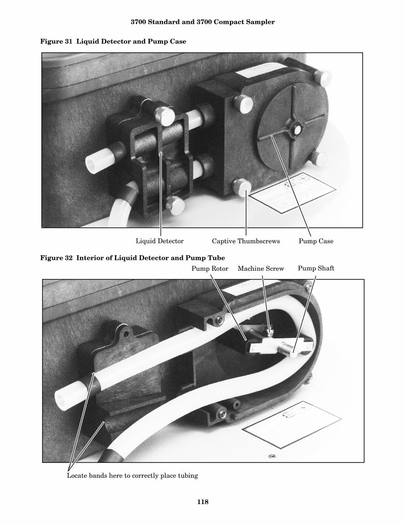
3700 Standard and 3700 Compact Sampler
118
Figure 31 Liquid Detector and Pump Case
Figure 32 Interior of Liquid Detector and Pump Tube
Liquid Detector Captive Thumbscrews Pump Case
Pump Rotor Machine Screw Pump Shaft
Locate bands here to correctly place tubing
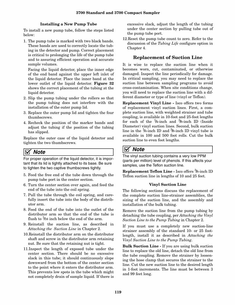
3700 Standard and 3700 Compact Sampler
119
Installing a New Pump Tube
To install a new pump tube, follow the steps listedbelow:
1. The pump tube is marked with two black bands.These bands are used to correctly locate the tub-ing in the detector and pump. Correct placementis critical to prolonging the life of the pump tubeand to assuring efficient operation and accuratesample volumes. Facing the liquid detector, place the inner edgeof the end band against the upper left inlet ofthe liquid detector. Place the inner band at thelower outlet of the liquid detector. Figure 32shows the correct placement of the tubing at theliquid detector.
2. Slip the pump tubing under the rollers so thatthe pump tubing does not interfere with theinstallation of the outer pump lid.
3. Replace the outer pump lid and tighten the fourthumbscrews.
4. Recheck the position of the marker bands andadjust the tubing if the position of the tubinghas slipped.
Replace the outer case of the liquid detector andtighten the two thumbscrews.
NoteFor proper operation of the liquid detector, it is impor-tant that its lid is tightly attached to its base. Be sure to tighten the two captive thumbscrews tightly.
5. Feed the free end of the tube down through thepump tube port in the center section.
6. Turn the center section over again, and feed theend of the tube into the coil spring.
7. Pull the tube through the coil spring, and care-fully insert the tube into the body of the distrib-utor arm.
8. Feed the end of the tube into the outlet of thedistributor arm so that the end of the tube isflush to 1/16 inch below the end of the arm.
9. Reinstall the suction line, as described inAttaching the Suction Line in Chapter 2.
10.Reinstall the distributor arm on the distributorshaft and screw in the distributor arm retainingnut. Be sure that the retaining nut is tight.
11.Inspect the length of exposed tube under thecenter section. There should be no excessiveslack in this tube; it should continuously slopedownward from the bottom of the center sectionto the point where it enters the distributor arm.This prevents low spots in the tube which mightnot completely drain of sample liquid. If there is
excessive slack, adjust the length of the tubingunder the center section by pulling tube out ofthe pump tube port.
12.Reset the pump tube count to zero. Refer to thediscussion of the Tubing Life configure option inChapter 4.
Replacement of Suction LineIt is wise to replace the suction line when itbecomes worn, cut, contaminated, or otherwisedamaged. Inspect the line periodically for damage.In critical sampling, you may need to replace thesuction line between sampling programs to avoidcross-contamination. When site conditions change,you will need to replace the suction line with a dif-ferent diameter or type of line (vinyl or Teflon).
Replacement Vinyl Line - Isco offers two formsof replacement vinyl suction lines. First, a com-plete suction line, with weighted strainer and tubecoupling, is available in 10-foot and 25-foot lengthsfor each of the 1/4-inch and 3/8-inch ID (InsideDiameter) vinyl suction lines. Second, bulk suctionline in the 1/4-inch ID and 3/8-inch ID vinyl tube isavailable in 100 and 500 foot rolls. Cut the bulksuction line to even foot lengths.
NoteThe vinyl suction tubing contains a very low PPM (parts per million) level of phenols. If this affects your samples, use the Teflon suction line.
Replacement Teflon Line - Isco offers 3/8-inch IDTeflon suction line in lengths of 10 and 25 feet.
Vinyl Suction Line
The following sections discuss the replacement ofthe complete suction line-strainer assemblies, thesizing of the suction line, and the assembly andinstallation of the bulk tubing.
Remove the suction line from the pump tubing bydetaching the tube coupling, per Attaching the VinylSuction Line to the Pump Tubing in Chapter 2.
If you must use a completely new suction-linestrainer assembly of the standard 10- or 25 foot-length, install it as described in Attaching theVinyl Suction Line to the Pump Tubing.
Bulk Suction Line - If you are using bulk suctionline to replace the old line, detach the old line fromthe tube coupling. Remove the strainer by loosen-ing the hose clamp that secures the strainer to theline. Cut the new suction line to the desired lengthin 1-foot increments. The line must be between 3and 99 feet long.

3700 Standard and 3700 Compact Sampler
120
To ensure accurate sample volumes, be sure thatthe line is cut in 1-foot increments and that theline length is correctly entered in the Suction Lineconfigure option. Install the strainer on the newsuction line and tighten the hose clamp. You cannow install the new suction line in the pump asdescribed in the section Attaching the Vinyl Suc-tion Line to the Pump Tubing.
Teflon Suction Line
Remove the suction line from the pump by loosen-ing the clamp that secures the line to the pumptube and pulling the suction line out of the pumptube. If you must use a new suction line (eitherwith or without the optional stainless steelstrainer), install it as described in the sectionAttaching the Teflon Suction Line to the Pump Tub-ing (Chapter 2). To install the optional stainlesssteel strainer, carefully slip the strainer's taperedconnector inside the suction line and tighten thehose clamp supplied with the strainer, as shown inFigure 5.
Changing the Internal DesiccantA humidity indicator, labeled “INTERNAL CASEHUMIDITY,” is located in the lower left corner ofthe control panel. It indicates the amount of mois-ture present inside the control box. The paper indi-cator is blue when the control box is dry.
The control box is a completely sealed unit. You donot need to open the control box during normaloperation. The desiccant should absorb any mois-ture that may accumulate in the control box. Thus,the humidity indicator should remain blue undernormal conditions. If moisture does accumulate,the numbered areas on the indicator will turn lightpink or white, starting with the area numbered“20.” This indicates that the relative humidityinside the control box exceeds 20%. As more mois-ture accumulates, the areas numbered “30” and“40” will turn light pink or white, indicating rela-tive humidities of 30% and 40% respectively.
CAUTIONThe control box contains electronic circuitrywhich may be damaged by static discharge.Open the control box only in a static free envi-ronment, as described in Precautions for Ser-vicing CMOS Circuitry (Chapter 7).
If the 30% area of the humidity indicator turnslight pink or white, open the control unit, inspect itfor leaks, and renew the desiccant. To do so,unscrew the 10 screws (indicated in Figure 33)around the outer rim of the control box bezel, andcarefully lift the bezel and cover off the control box.
Inspect the Control Box - If there is a leak,repair it by referring to the previous section, or byreturning the control box to the factory. The fac-tory has specialized equipment to detect leaks andthoroughly test the units after repair.
Renewing the Desiccant - If you do not detect aleak, renew the desiccant by removing the bags ofdesiccant from the control box (see Figure 34).
Place the bags on top of a sheet of brown on a flatmetal sheet. You can use a brown grocery bag and atypical cookie sheet. Do not stack the bags on top ofeach other or allow them to touch. Place in a vented,circulating forced air, conventional oven in a wellventilated room. Allow two inches of air spacebetween the top of the bags and the next metal trayabove the bags. Keep the tray a minimum of 16inches from the heating element. Heat the bags at atemperature of 240 to 250°F (116 to 121°C) for 12 to16 hours. At the end of the time period, the bagsshould be immediately removed and placed in an airtight container for cooling. The desiccant will berecharged to approximately 80 to 90% of its previ-ous capacity. After repeated recharging, the desic-cant bag may require replacement.
Some bags will have the temperature and time forrecharging the desiccant printed on the bag. Ifthey differ, use the temperature and time printedon the bag.
Before reinstalling the cover, coat the cover's gas-ket with a light film of silicone grease to seal thecontrol box. Tighten the 10 screws that hold thecontrol box cover and bezel in place using an evencross-torquing pattern.

3700 Standard and 3700 Compact Sampler
121
Figure 33 Location of 10 Screws on Control Box Bezel
Figure 34 Internal Desiccant
Humidity Indicator
1 of 10 Screws
3700 Standard and 3700 Compact Sampler
122
Chapter 7 ServicingIntroduction
This chapter presents servicing information for the3700 Portable Samplers in the following sections:
• Servicing the controller;• Control box removal; • Removal of the distributor and pump-gear
cases;• General care of CMOS circuitry;• Circuit description of the electronic circuitry;• Sample event cycle.
Included is an illustrated Replacement Parts Listand a list of available accessories available for the3700 Sampler. For information on servicing andreplacing power sources, consult the Isco PowerProducts Guide, shipped with this manual.
Servicing the Controller The electronic circuitry of the 3700 Sampler issolid-state and its reliability is high. If the unitshould fail to operate properly, items such as a bro-ken or intermittent connection in the power cableor wiring harness should be suspected.
If Serious Problems Occur - If you suspect anelectronic problem, Isco strongly recommends call-ing the Isco Customer Service Department at (800)775-2965, or (402) 474-2233 outside the U.S.A.,Canada, and Mexico. The service department willprovide information on how to return the sampleror subassemblies to the factory for service. Forexample, you can remove the pump assembly, dis-tributor assembly, or control box and return themseparately for servicing.
Because of the complex nature of microprocessor-based circuitry, specialized knowledge and instru-mentation are required for troubleshooting. TheIsco service department has trained technicians andspecially designed equipment necessary for timely,efficient repair of the sampler. If you wish toattempt repairs, the Isco Customer Service Depart-ment is available to provide advice on servicing.
Processor Servicing - Servicing microprocessor-controlled circuitry is difficult when you do notunderstand the program that controls it com-pletely, especially when there is no way to be cer-tain that the microprocessor is functioningproperly. When you attempt to isolate problemswithin the unit, assume that the CPU and memoryare working properly until you have eliminated thepossible causes listed in Preliminary ElectronicsTroubleshooting Steps.
Removal of the Control Box
If there is a problem with the sampler thatrequires you to ship your unit back to the factory, itis often easiest to return only the control box forrepair. To remove the control box from the sampler:
1. Disconnect the power source from the control box. 2. Separate the center section from the sampler
following the procedure described in Assemblyand Disassembly of the Case in Chapter 2.
3. Remove the suction tube from the pump, and turnthe center section over, as shown in Figure 35.
4. Unscrew the distributor arm retaining nut, indi-cated in Figure 35, and pull the arm off the dis-tributor shaft.
5. Pull the pump tube out of the distributor armand coil spring assembly, and feed it out of thepump-tube port in the center section.
6. You can then remove the control box by unscrew-ing the six screws indicated in Figure 35, andlifting the center section off the control box.
7. Screw the six screws and their lockwashers intothe control box to prevent losing them.
8. Reattach the liquid-detector lid and pump lid toprevent their loss.
NoteWhen you return the control box to the factory,be sure to pack it securely. Take special careto protect the distributor shaft. Please includea detailed note explaining the problem.
Access to Electronic Components
To gain access to the electronic components housedin the control box:
CAUTIONThe voltage levels produced by static buildupfrom walking over carpeted floors, movementof woolen or synthetic clothes over chair seats,workbenches, etc., are high enough to destroyCMOS circuitry when you are performing repairwork.
1. Disconnect the power source from the sampler. 2. Remove the 10 screws around the outer edge of
the control-box bezel, as indicated in Figure 33.3. Lift the cover and bezel off the control box and
turn it over, as shown in Figure 36. 4. You can disconnect the control-box cover assembly
from the control-box lower section by disconnect-

3700 Standard and 3700 Compact Sampler
123
ing the five connectors indicated in Figure 36,and the grounding strap.
5. The main circuit board assembly of the 3700 isprotected by an aluminum shield. To remove thisshield, unscrew the four screws and the nut shownin Figure 36, and lift off the shield. This revealsthe main circuit board, shown in Figure 37.
6. To remove the circuit-board assembly from thecontrol box cover, unscrew the four hex-threaded
stand-offs and the Phillips head screw, shown inFigure 37. You can now pull the circuit boardaway from the control box cover.
7. To disconnect the circuit board assembly fromthe cover, disconnect the connector shown inFigure 37.
The control box can be reassembled by reversingthese steps. Ensure that you replace all of thehardware and secure the grounding straps.
Figure 35 Removing the Control Box
Pump Tube Port
Distributor Arm Retaining Nut
32
65
1
4
Remove the control box by unscrewing six screws.
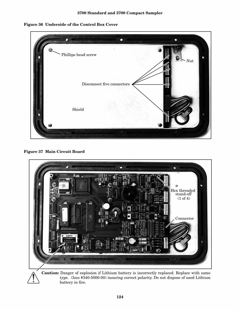
3700 Standard and 3700 Compact Sampler
124
Figure 36 Underside of the Control Box Cover
Figure 37 Main Circuit Board
Shield
Phillips head screw
Disconnect five connectors
Nut
Connector
Hex threaded
(1 of 4)stand-off
Caution: Danger of explosion if Lithium battery is incorrectly replaced. Replace with sametype. (Isco #340-5000-00) insuring correct polarity. Do not dispose of used Lithiumbattery in fire.
3700 Standard and 3700 Compact Sampler
125
Removal of the Distributor Gear Case Assembly
The distributor gear case assembly is located inthe lower section of the control box. To gain accessto the lower section of the control box, follow theinstructions in the Access to Electronic Compo-nents section. Follow the steps below to gain accessto these and other components in the lower sectionof the control box:
1. Disconnect power from the unit.2. Remove the 2 nuts and the screw shown in Fig-
ure 38. Remove the ground strap by removingthe remaining screw.
3. Lift the plastic tray straight up out of the con-trol box.
4. The distributor gear case can be removed fromthe control box by removing the four screws andthe ground straps shown in Figure 39.
The distributor gear case can be reinstalled byreversing these steps. Ensure that you replace allof the hardware and secure the grounding straps.
Removal of the Pump Gear Case Assembly
The pump-gear case assembly is located in thelower section of the control box. For access to thelower section of the control box, follow the instruc-tions in the section entitled Access to ElectronicComponents. Follow the steps below to remove thepump gear case.
1. Remove the distributor gear case as discussed inRemoval of the Distributor Gear Case Assembly.
2. Remove the liquid detector lid and the pump lidby loosening the captivated thumbscrews on thepump exterior. Figure 31 shows the location ofthe thumbscrews.
3. Remove the pump tubing from the interior ofthe pump.
4. Remove the pump rotor by loosening themachine screw and lock nut attaching the rotorto the pump shaft. Figure 32, Interior of LiquidDetector and Pump Tube, in Chapter 6, showsthe location of the machine screw. Rotate therotor until you can reach the screw with ascrewdriver inserted through the pump-caseinlet sleeve.
5. Slide the rotor off the pump shaft.6. Remove the pump case by unscrewing the four
screws on the back of the pump’s inner case. 7. Carefully lift the pump gear-case assembly out
of the control box.
The pump gear case can be reinstalled by revers-ing these steps. Ensure that you replace all of thehardware and secure the grounding straps.
Precautions for Servicing CMOS Circuitry
Most of the circuitry in the 3700 Portable Samplersis made up of CMOS components. Because of theoxide gate structure of these devices, they areextremely susceptible to destruction caused by thedischarge of static electricity through their inputs.Because of this risk, you must take certain precau-tions when working on these circuits.
Hazard of Static Electricity - The voltage levelspresent from static buildup from walking over car-peted floors, movement of woolen or syntheticclothes over chair seats, workbenches, etc., arehigh enough to destroy CMOS circuitry when youare performing repair work.
Ideally, all tools, soldering irons, etc., should begrounded, and you should conduct all work on agrounded metal workbench, with a groundingstrap worn around your wrist. Obviously, in fieldrepair situations, such precautions are impractical.However, you must avoid certain extreme hazards.
1. Never perform any work in a room with a car-peted floor.
2. Always roll up the sleeves of work clothes sothat your arms are in contact with the workingsurface.
3. Avoid using a work surface made of anextremely good insulator. Avoid laminatedcounter tops and glass, which are good insula-tors. A metal surface is best; a wood surface isacceptable. Conductive grounding mats areavailalble for workstations and are worthwhileif you have a considerable amount of repair todo.
4. The degree of hazard depends on the relativehumidity. Be particularly careful if the workarea is extremely dry, or if the work is beingdone in the winter, when indoor forced heatingand outdoor low temperatures cause the relativehumidity level to be very low.
5. Keep yourself grounded when handling disas-sembled equipment. When you arrive at thework area after a unit has been opened forrepair, make an effort to always touch the metalchassis before touching any of the circuit compo-nents.
6. Be especially careful handling the CMOS-inte-grated circuits when removing them from therest of the circuitry. Being connected to the restof the circuitry provides some protection. Mostof the circuitry is well protected from damagecaused by static discharge when the unit is pow-ered up. However, an IC should never bereplaced when the unit is on.
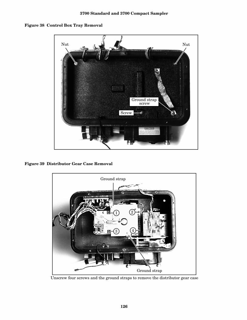
3700 Standard and 3700 Compact Sampler
126
Figure 38 Control Box Tray Removal
Figure 39 Distributor Gear Case Removal
Nut Nut
Screw
screwGround strap
Ground strap
Ground strap
1
3
2
4
Unscrew four screws and the ground straps to remove the distributor gear case

3700 Standard and 3700 Compact Sampler
127
7. Individual CMOS semiconductors and built-upprinted circuit boards should always be trans-ported in conductive packaging. Foil is satisfac-tory; metallic plastic bags are also available andwork well. If you purchase replacement compo-nents that do not come in marked, protectivepackaging, do not use them. They may alreadybe destroyed.
8. Once assembled and soldered, printed circuitboards are easily damaged by improper repairprocedures. Do not attempt to remove compo-nents, particularly ICs, from printed circuitboards unless you are skilled at this procedure.You can locate and change a defective compo-nent, and the unit may still not work if excessiveheat or pressure has broken the foil traces orpulled the cores from holes on the board.
Contact Customer Service - If trouble symp-toms persist and you are unable to locate thecause, call the Customer Service Department at(800) 228-4373.
Preliminary Electronics Troubleshooting Steps
Isco suggests checking the following possible prob-lem areas before attempting to service the micro-processor CPU and associated circuitry.
1. Be sure that the supply voltage is correct.2. Check to see that the wiring harnesses, connec-
tors, and solder joints are in good condition.3. Look for signs of physical damage, such as
burned or broken components, overly hot compo-nents, or evidence of water damage.
4. Check for shorted or open diodes and transis-tors, especially driver transistors.
5. Ensure that voltage regulators working properly.6. Check to see if there is excessive current draw
in some or all of the circuitry.7. Be sure that correct input signals are sent to the
unit.8. Check to see that the crystal oscillator is operat-
ing and at proper frequency.9. Examine the reset circuitry to be sure that it is
working properly. 10. Check lithium battery for 3 VDC output when
main power is removed.
Circuit Boards
The following is a general description of the 3700Sampler electronic circuitry. While reading thisdescription, refer to the schematic diagram (Fig-ure 41), the case schematic diagram (Figure 43),and the pictorial views of the circuit boards (Fig-ures 40 and 42).
The 3700 Sampler is a microprocessor-based devicethat executes a software program stored in ROM.The program is a series of instructions that tell themicroprocessor what to do in order to accomplishthe various functions that the sampler must per-form. In the following discussion of the hardware,the software is discussed only as is necessary todescribe the operation of the circuitry. The A 12VDC connector on the side of the control box isused to connect to an external 12 V source. A 3.75Amp PTC device provides circuit protection.
The 3700 Sampler contains two printed circuitboards: the main board and the pump-control board.The display module (attached to the main circuitboard) also contains a small circuit board. This mod-ule is fully assembled when purchased. It does notcontain any user-serviceable parts. Unless the dis-play module is being replaced, do not disturb it.
Main Board - P4 supplies power to the circuitrypin 1 is ground and pin 2 is 12 volts. A 5-voltswitching regulator (IC U11) obtains a 5-volt railfrom the 12-volt supply.
All of the ICs used in the 3700 Samplers are pow-ered from the 5-volt rail. IC U11 is also used as alow-voltage detector, constantly monitoring the 12-volt supply. IC U17.
A voltage converter, provides a -5-volt supply,which some components require. IC U8 is themicroprocessor, IC U5 is the ROM, and IC U7 isthe RAM. These three ICs make up the brains ofthe 3700 Sampler. The microprocessor executes theprogram stored in ROM. While executing, informa-tion (program settings, sample data, etc.) isretrieved from and stored in RAM. A 4.608 MHzcrystal oscillator (Y1) sets the microprocessor’sexecution speed.
The 3700 Sampler keeps track of time with a real-time clock (IC U3). Both the RAM and IC U3 arebattery-backed with a lithium battery (B1). IC U1is a switch that selects between battery and sys-tem power.
Three devices allow the microprocessor to commu-nicate with the outside world: the 2-line, 20-char-acters-per-line LCD, IC U9, and IC U18. The LCDfacilitates communication with the user and is con-nected through P3. IC U13, transistor Q2, ther-mistor R15, and other components provide theLCD with a temperature compensated driver volt-age. By providing temperature compensation, thedisplay quality is optimized over a wide tempera-ture range. IC U9 and IC U18 are I/O devices,which allow the microprocessor to read the keypad,sound the beeper, advance the distributor, measurepump counts, and so on.
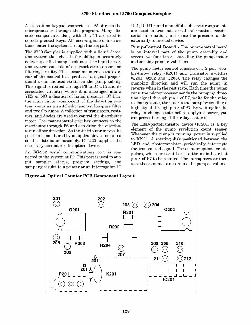
3700 Standard and 3700 Compact Sampler
128
A 24-position keypad, connected at P5, directs themicroprocessor through the program. Many dis-crete components along with IC U11 are used todecode pressed keys. All user-originated instruc-tions enter the system through the keypad.
The 3700 Sampler is supplied with a liquid detec-tion system that gives it the ability to accuratelydeliver specified sample volumes. The liquid detec-tion system consists of a piezoelectric sensor andfiltering circuitry. The sensor, mounted on the exte-rior of the control box, produces a signal propor-tional to an induced strain on the pump tubing.This signal is routed through P8 to IC U15 and itsassociated circuitry where it is massaged into aYES or NO indication of liquid presence. IC U15,the main circuit component of the detection sys-tem, contains a switched-capacitor, low-pass filterand two Op Amps. A collection of transistors, resis-tors, and diodes are used to control the distributormotor. The motor-control circuitry connects to thedistributor through P6 and can drive the distribu-tor in either direction. As the distributor moves, itsposition is monitored by an optical device mountedon the distributor assembly. IC U20 supplies thenecessary current for the optical device.
An RS-232 serial communications port is con-nected to the system at P9. This port is used to out-put sampler status, program settings, andsampling results to a printer or an interrogator. IC
U21, IC U19, and a handful of discrete componentsare used to transmit serial information, receiveserial information, and sense the presence of theexternally connected device.
Pump-Control Board - The pump-control boardis an integral part of the pump assembly andserves two functions: controlling the pump motorand sensing pump revolutions.
The pump motor control consists of a 2-pole, dou-ble-throw relay (K201) and transistor switches(Q201, Q202 and Q203). The relay changes thepumping direction and will run the pump inreverse when in the rest state. Each time the pumpruns, the microprocessor sends the pumping direc-tion signal through pin 1 of P7, waits for the relayto change state, then starts the pump by sending ahigh signal through pin 3 of P7. By waiting for therelay to change state before applying power, youcan prevent arcing at the relay contacts.
The LED-phototransistor device (IC201) is a keyelement of the pump revolution count sensor.Whenever the pump is running, power is suppliedto IC201. A rotating disk positioned between theLED and phototransistor periodically interruptsthe transmitted signal. These interruptions createpulses, which are sent back to the main board atpin 8 of P7 to be counted. The microprocessor thenuses these counts to determine the pumped volume.
Figure 40 Optical Counter PCB Component Layout
201 202203 204
205
206 207
208 209 210
211 212
IC201K201
201
201
C
D
Q201 Q202R201
R202
R203 R204
P201
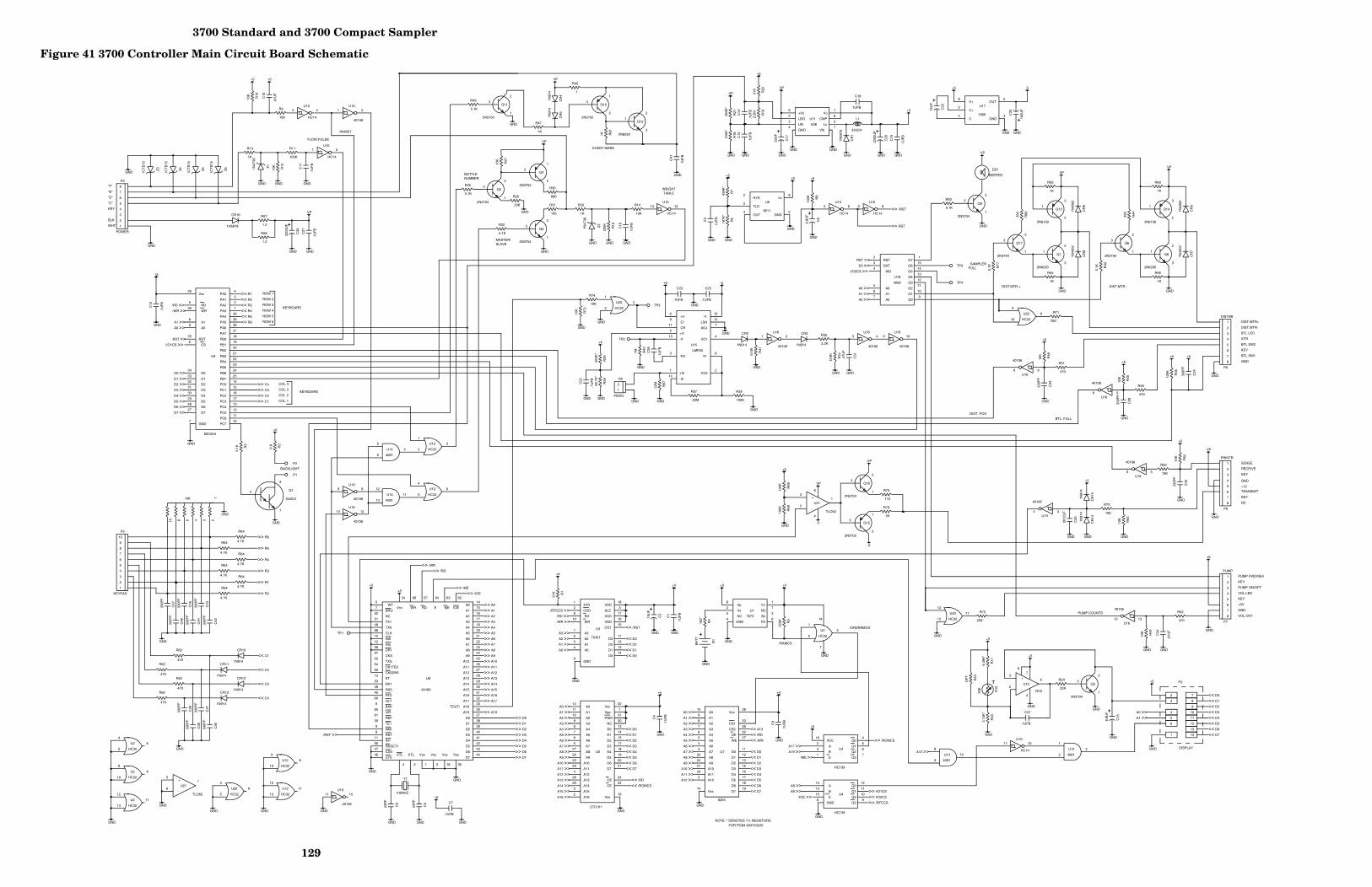
3700 Standard and 3700 Compact Sampler
129
Figure 41 3700 Controller Main Circuit Board Schematic
TOUT/
+Vs
LBO
LBI
GND Vfb
Lx
CMP
Vo
V+
C+
C- GND
OUT
Vp
Vs
NC
GND Pb
Sb
NC
Vo
HYS
TLD
OUT GND
V+
Vcc
RD
WR
A1
A0
RST
CS
D0
D1
D2
D3
D4
D5
D6
D7
GND PC7
PC6
PC5
PC4
PC3
PC2
PC1
PC0
PB7
PB6
PB5
PB4
PB3
PB2
PB1
PB0
PA7
PA6
PA5
PA4
PA3
PA2
PA1
PA0
Q0
Q1
Q2
Q3
Q4
Q5
Q6
Q7
A2
A1
A0
WD
DAT
RST
WT
BRQ
NC
TX1
TX0
CLK
IN0
IN2
DR1
CKS
TXS
CK1TE0
CK0DR0
ST
RX1
RX0
RT0
HLT
BAK
LIR
REF
TE1
NMI
RST
IN1
RXSCT1
CD0
CT0 XTL XTL Vss Vss Vss Vss
D7
D6
D5
D4
D3
D2
D1
D0
A19
A18
A17
A16
A15
A14
A13
A12
A11
A10
A9
A8
A7
A6
A5
A4
A3
A2
A1
A0 IOE ME E RD WR Vcc
+
-
+V
CI
CR
+I1
-I1
FO
+I2
-I2
VO2
FI
VO1
ADJ
LSH
-V
A0
A1
A2
A3
A4
A5
A6
A7
A8
A9
A10
A11
A12
D7
D6
D5
D4
D3
D2
D1
D0
WE
OE
Vcc
CS2
CS1
Vss
STD
CSO
RD
WR
A3
A2
A1
A0
GND
D0
D1
D2
D3
CS1
VDD
VDD
ALE
VDD
A0
A1
A2
A3
A4
A5
A6
A7
A8
A9
A10
A11
A12
A13
A14
A15
A16 Vss
CE
OE
D7
D6
D5
D4
D3
D2
D1
D0
NC
PGM
Vpp
Vcc
+
-
+
-
VCC
A
B
E Q3
Q2
Q1
Q0
A
B
E
Q3
Q2
Q1
Q0
GND
6
2
3
4 7
5
8
1
8
2
4 3
5
3
1
2
6
4
5
8
9
10
11
12
13
3
1
2
6
4
5
8
9
10
11
12
13
8
2
5
4 6
3
7
1
1 2 3 4
5 6
9 8
11 10
13 12
1 2
3 4
5 6
9 8
11 10
13 12
2
3
4 5
8
26
5
36
8
9
35
6
34
33
32
31
30
29
28
27
7 10
11
12
13
17
16
15
14
25
24
23
22
21
20
19
18
37
38
39
40
1
2
3
4
9
10
11
12
13
14
15
1
7
6
5
4
3
2
5
7
52
51
48
68
10
12
58
57
55
54
50
13
53
49
45
60
6
65
61
59
9
8
11
56
47
46
4 3 1 2 18 36
44
43
42
41
40
39
38
37
35
33
32
31
30
29
28
27
26
25
24
23
22
21
20
19
17
16
15
14 62 63 64 67 66 34
3
2
4
6
7 8
6
9
11
5
13
3
1
14
2
8
4
7
12
10
10
9
8
7
6
5
4
3
25
24
21
23
2
19
18
17
16
15
13
12
11
27
22
28
26
20
14
1
2
8
10
7
6
5
4
9
14
13
12
11
15
16
17
3
18
11
12
13
8
9
10
6
4
5
1
2
3
7
14
1
2
3
1
2
3
1
2
3
1
2
3
1
2
3
1
2
3
1
2
3
1
2
3
1
2
3
1
2
3
1
2
3
3
2
1
1 2 3 4 6 8 10
1
2
3
4
5
6
7
8
1
2
3
4
5
6
7
8
1
2
3
4
5
6
7
8
1
2
3
4
5
6
7
8
1
2
3
4
5
6
7
8
9
10
1
2
3
4
5
6
7
8
9
10
11
12
13
14
1
2
1
3
2
5
4
6
8
10
9
12
11
13
12
11
10
9
8
7
6
5
27
26
23
25
4
28
29
3
2 16
22
24
21
20
19
18
17
15
14
13
30
31
1
32
3
2
4
1
8
5
6
7
1
2
3
1 2
3 4
5 6 9 8
11 10
13 12
16
2
3
1 7
6
5
4
14
13
15
9
10
11
12
8
3
2
1
3
2
1
3
2
1
3
2
1
U11
U17
U12
U12
U12
U12
U20
U20
U20
U20 U1
U16 U16
U16
U16
U16
U16
U19
U19
U19
U19
U19
U19
U6
U9
U18
U8
U13
U15
U7
U3
U2
U2
U2
U2
Z3
Z4
Z5
Z6
CR16
CR
1
Z1
Z2
CR2 CR3
CR
4 C
R5
CR10
CR11
CR12
CR13
CR
14
CR
15
CR
8
CR
9
CR
6
CR
7
Q4
Q10
Q15
Q5
Q3
Q2
Q9
Q11
Q17 Q6
Q16
Q12
C20
C30
C17
C29
C8
C15
C31
C2
L1
B1
Y1
DS1
R5
R2
R19
R1
R22
R10
R12
R8
R11
R32
R26
R27
R30
R23
R25
R33
R24
R16
R14
R41
R36
R35
R34
R40
R39
R43
R37
R38
R46
R47
R48
R50
R49
R53
R54
R51
R52 R
61
R77
R42
R63
R59 R60
R68
R
69 R70
R55 R56
R73
R74
R75
R67
R76
R9
R4
R21
R
6 R
7
R20
R
17
R28
R
29
R71
R72
R18
R3
R13
R66
R44
R45
R31
R57
R58
R15
P4
P6
P7
P9
P5
P1
P2
TP1
TP3
TP4
TP5
P8
TP2
U14
U14
U14
U14
C32
R62
R62
R62
R62
U5
C40
U21
U21
R64
R64
R64
R64
R64
R64
Q1
U10
U10
U10 U10
U10
U10
U4
U4
C13
C
14
C1
C18
C19
C4
C11
C9
C7
C3
C12
C21
C16
C23
C22
C27
C25
C26
C41
C34
C10
C39
C38
C37
C36
C
42
C43
C44
C45
C46
C47
C24
C28
C33
C35
C5
C6
Q13 Q14
Q7 Q8
638
7660
HC32
HC32
HC32
HC32
HC32
HC32
HC32
HC32 7673
40106 40106
40106
40106
40106
40106
40106
40106
40106
40106
40106
40106
8211
82C55A
4099
64180 7612
6264
72421
HC32
HC32
HC32
HC32
ICT
E15
ICT
E15
ICT
E15
ICT
E15
1N5818
1N58
18
1N47
36
1N47
36
1N914 1N914
1N91
4 1N
914
1N914
1N914
1N914
1N914
1N91
4 1N
914
1N40
02
1N40
02
1N40
02
1N40
02
2N3702
2N3702
2N3702
2N3704
2N3704
2N3704
2N3704
2N3704
2N3704 2N3704
2N3704
2N6290
2200
UF
2200
UF
33U
F
15U
F
6.8U
F
6.8U
F
.47U
F
15U
F
330UH
BA
TT
4.6MHZ
BEEPER
220K
5.1K
2.2M
51K
51K
10K
10K
100K
100K
5.1K
33K
10K
680
OP
T
5.1K
1K
22K
220K
10K
510K
100K
2.2K
510K
10K
100K
1M
22M
470
5.1K
1K
10K
5.1K
10K
10K
10K
470
470
1K
5.1K
5.1K
10K
1K 1K
100K
10
0K
10K
1K 1K
10K
10K
110
22M
39
10K
100*
499K
* 18
7K*
499K
*
3.74
K*
6.49
K*
68.1
K*
604K
*
255*
200*
100K
*
6.8
1K
390
390
1
100
1.2
1.2
30K
POWER
DISTRB
PUMP
PRINTR
KEYPAD
PIEZO
4081
4081
4081
4081
100U
F
470
470
470
470
27C101
0012
UF
TLO62
TLO62
4.7K
4.7K
4.7K
4.7K
4.7K
4.7K
D40C2
HC14
HC14
HC14 HC14
HC14
HC14
HC139
HC139
.1U
FB
.1
UF
B
.1U
FB
.1UFB
.1U
FB
.1U
FB
.1U
FB
.1U
FB
.1UFB
.1U
FB
.1U
FB
.1UFB
.1U
FB
.1UFB
.1U
FB
.1U
FB
.1UFB
.1U
FB
.1U
FB
.01U
F
.01U
F
330P
F
330P
F
330P
F
330P
F
330P
F
330P
F
330P
F
330P
F
330P
F
330P
F
330P
F
330P
F
330P
F
330P
F
22P
F
22P
F
2N6109 2N6109
2N6290 2N6290
GND
VP
GND GND
VP
GND GND
GND
VP
+5
GND
GND GND GND
+5
GND GND
-5
GND
+5
GND
GND
GND
+5 +5
GND GND GND
GND
GND
VP
GND
GND
GND
GND
+5 +5 +5
>> RST
>> /RST
GND
>> R6
>> R5
>> R4
>> R3
>> R1
>> R2
GND
<< C4
<< C3
<< C2
<< C1
GND GND
VP
VP
<< D0
<< D1
<< D2
<< D3
<< D4
<< D5
<< D6
<< D7
A0 >>
A1 >>
A2 >>
A3 >>
A4 >>
A5 >>
A6 >>
A7 >>
A8 >>
A9 >>
A10 >>
A11 >>
A12 >>
A13 >>
A14 >>
A15 >>
<< /RD
<< /ROMCS
GND
A17 >>
A19 >>
/ME >>
/IOE >>
>> /ROMCS
>> I/O1CS
>> I/O2CS
>> /RTCCS
+5
<< R1
<< R2
<< R3
<< R4
<< R5
<< R6
>> C1
>> C2
>> C3
>> C4
/RD >>
/WR >>
A1 >>
A0 >>
RST >>
I/O1CS >>
D0 >>
D1 >>
D2 >>
D3 >>
D4 >>
D5 >>
D6 >>
D7 >>
GND
GND
VP
RST >>
D0 >>
I/O2CS >>
A0 >>
A1 >>
A2 >>
GND GND
GND
>> D7
>> D6
>> D5
>> D4
>> D3
>> D2
>> D1
>> D0
>> A19
>> A17
/RST >>
+5
>> /WR
>> /RD
>> /ME
>> /IOE
>> A0
>> A1
>> A2
>> A3
>> A4
>> A5
>> A6
>> A7
>> A8
>> A9
>> A10
>> A11
>> A12
>> A13
>> A14
>> A15
+5
GND GND
GND
A0 >>
A1 >>
GND
+5
<< D0
<< D1
<< D2
<< D3
<< D4
<< D5
<< D6
<< D7
GND GND
+5
GND
GND
+5 -5
GND
GND
GND
GND GND
GND
GND
+5
GND GND
+V
GND
<< /RD
<< /WR
<< D0
<< D1
<< D2
<< D3
<< D4
<< D5
<< D6
<< D7
A0 >>
A1 >>
A2 >>
A3 >>
A4 >>
A5 >>
A6 >>
A7 >>
A8 >>
A9 >>
A10 >>
A11 >>
A12 >>
+5
+V
<< /RST
<< D3
<< D2
<< D1
<< D0
GND
A0 >>
A1 >>
A2 >>
A3 >>
/RTCCS >>
/RD >>
/WR >>
GND GND
GND
+5
GND
GND
+5
<< A13
GND
GND
+5
+V
+5
GND
GND
GND
+5
GND
GND
VP
+5 +5
A8 >>
A9 >>
GND
GND
+5
GND
GND GND GND
GND
GND
GND
A16 >>
GND GND GND
+5 VP
-5
-5
VP
+5
GND
GND
+5
+5
GND
GND
VP
GND
+5
GND
>> A16
GND GND GND
GND
A12 >>
+5
GND
/RAMCS
/ORDRAMCS'
INHIBIT
FLOW PULSE
EVENT MARK
ROW 1
ROW 2
ROW 3
ROW 4
ROW 5
ROW 6
KEYBOARD
COL 1
COL 2
COL 3
COL 4
KEYBOARD
SAMPLER FULL
DIST.MTR.- DIST.MTR.+
DISPLAY
VOL LED
VOL CNT
PUMP FWD/REV
KEY
PUMP ON/OFF
KEY
+5V
GND
MASTER/ SLAVE
DIST.MTR+
DIST.MTR-
GND
KEY
WHT
BLK
KEY
"C"
"D"
"E"
"F"
BOTTLE NUMBER
BTL LED
XTR
BTL SW2
BTL SW1
DIST. POS
BTL. FULL
PUMP COUNTS
NOTE: * DENOTES 1% RESISTORS
WEIGHT TABLE
10K
KEY
TRANSMIT
SENSE
KEY
NC
BACKLIGHT
GND
+12
P3
RECEIVE
FOR PCB# 603703245
LMF60

3700 Standard and 3700 Compact Sampler
130
Figure 42 Main Circuit Board Component Layout
OU
T
OU
T
OU
T
OU
T
OU
T
OU
T
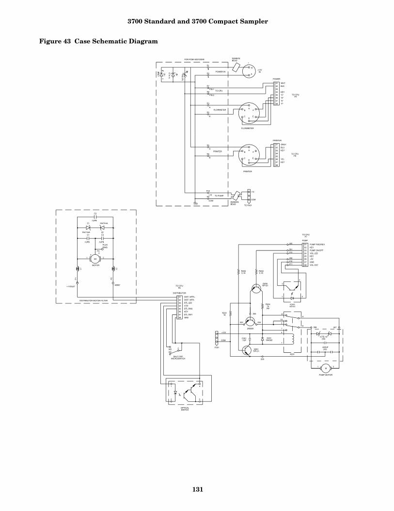
3700 Standard and 3700 Compact Sampler
131
Figure 43 Case Schematic Diagram
01
02
03
04
05
06
07
08
PUMP FWD/REV
KEY
PUMP ON/OFF
VOL LED
KEY
+5V
GND
VOL CNT
205
201
212
209
210
211
PUMP
M
R2025.1K
R2035.1K
4
3
1 2
IC201H21A1
R204752W
Q202TIP121
2N5881
8
10
5
7
4
1
9
6208 207
.022UF(X3)
PUMP MOTOR
K201
206
D2011N4002
C201.1UF
Q201TIP121
203
204202
R2011K
+12V
COM
P201
01
02
03
04
05
06
07
08
1
2 3
4
NONC
C
SHUT-OFFMICROSWITCH
OPTICALSWITCH
DISTRIBUTOR
DIST. MTR+
DIST. MTR-
BTL LED
XTR
BTL SW2
KEY
BTL SW1
GND
TO CPUP6
TO CPUP7
1 2
F
ED
C
BA
B
A
AB
CD
E
F
TO CPUP4
POWER
"F"
"E"
"D"
"C"
KEY
BLK
WHT
08
07
06
05
04
03
02
01
TO CPUP9
KEY
YEL
KEY
BLU
GRAY
PRINTER
01
02
03
04
05
06
07
08
DISTRIBUTOR MOTOR FILTER
RING FLUX
- GREY + VIOLET
MOTOR
.1UFB
.1UFB .1UFB
1N4744A
1N4744A
P3
P2
P1
L2
L1
M1
C2
C3 C1 Z2
Z1
3
2 1
+12VIN
+
FLOWMETER
PRINTER
+12
COM
TO P201
P2
A
A
B
B
COM
+12
PIN 1
PIN 2
B
A
P3
P5
P4
P6
P9
P10
P7
P8
P1
GND
POWER IN
FLOWMETER
PRINTER
TO CPU
TO PUMP
FOR PCB# 603703249 FERRITEBEAD
FERRITEBEAD
ICTE-15(X2)

3700 Standard and 3700 Compact Sampler
132
Sample Event Cycle and Delivery of Sample Volumes
The steps listed below describe a typical sequentialsample event in order to help you determine thecorrect sequence of events in the cycle. Should yoususpect a malfunction in the delivery of the samplevolumes, you can use this information to helpdetermine the point at which the problem occurs.
1. A sample event is initiated.2. The distributor rotates to the position of the
next sample bottle to be filled.3. The pump rotates in the reverse direction to air
purge the suction line inlet of any accumulateddebris.
4. The pump direction changes, pumping in theforward direction to fill the suction line.
5. After the suction line has been filled to thepump inlet, the sample volume measuring por-tion of the sampling cycle begins. The pumprotates in the forward direction until the samplevolume has been delivered.
6. The pump direction again changes, pumping inreverse to air purge the suction line to avoidcross-contamination of samples. The pump thenshuts off.
7. The sampler waits until another sample event isinitiated and the cycle begins again at Step 1.
This process continues until the last bottle hasbeen filled, at which time the sampler automati-cally shuts off.
The following section briefly describes the methodby which the sample volume is determined. The3700 uses a peristaltic pump to transport the sam-ple from the source to the sample bottle. Whencompared with other suction-lift sample gatheringmethods, the peristaltic pump has numerousadvantages: simplicity, reliability, no requisitemetering chamber, an easy-to-clean design, etc.
Volumetric Determination - The 3700 Samplerdetermines the volumetric delivery of its peristal-tic pump by electronically counting revolutions ofthe pump rotor. Each revolution of the pump rotorcorresponds to a fixed number of “pump counts”and a certain volume of sample liquid. However,the volume of liquid delivered by one revolution ofthe pump rotor changes with the suction head andthe type of suction line. At each sample event, the3700 liquid-detection system automatically com-pensates for changes in suction head and adjuststhe volume delivered for each revolution of thepump. Thus, for a given type of suction line, eachrevolution of the pump rotor results in the deliveryof a known amount of sample volume.
Sample Delivery - There are three parts to thesample pumping portion of a sample event: suc-tion-line fill, liquid detection, and sample-volumedelivery. The sampler counts the number of pumprevolutions as the suction line fills. At liquid detec-tion, the controller uses that count to determinethe number of pump revolutions required todeliver the programmed sample volume.
Sample Volume Variation - Be sure to note thatthe volume delivered by a peristaltic pump can beinfluenced by a number of factors other than thosediscussed above. Thus, even with the sophistica-tion of the sample-volume measuring functions ofthe 3700, the volume of sample deposited in thesample bottle may vary from the programmedvalue. The repeatability of a sample volume fromsample-to-sample (which normally is the mostimportant consideration) is typically within the ±10 ml specification.
Replacement Parts ListIn Appendix A, you will find a list of commonreplacement parts for use with the 3700 Compactor Standard Sampler. When you order a replace-ment part, be sure to include the Isco assembly orpart number, a complete description of the part,and the serial number of the sampler on which thepart will be used.
Accessory Parts ListAppendix B contains a list of options and acces-sory parts described throughout this manual. Whenyou order an option or accessory, be sure to includethe part description and the Isco part number.

3700 Standard and 3700 Compact Sampler
133

3700 Standard and 3700 Compact Sampler
134
Appendix A Replacement Parts Listing

3700 Standard and 3700 Compact Sampler
135
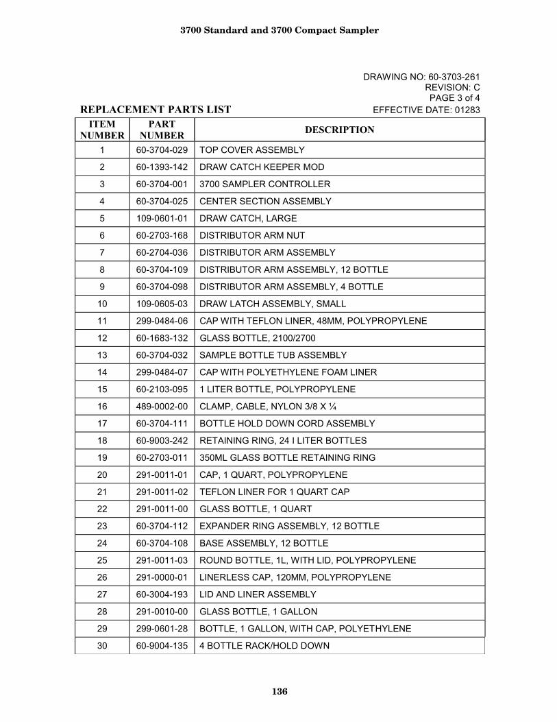
3700 Standard and 3700 Compact Sampler
136
DRAWING NO: 60-3703-261 REVISION: C PAGE 3 of 4
REPLACEMENT PARTS LIST EFFECTIVE DATE: 01283ITEM
NUMBER PART
NUMBER DESCRIPTION
1 60-3704-029 TOP COVER ASSEMBLY
2 60-1393-142 DRAW CATCH KEEPER MOD
3 60-3704-001 3700 SAMPLER CONTROLLER
4 60-3704-025 CENTER SECTION ASSEMBLY
5 109-0601-01 DRAW CATCH, LARGE
6 60-2703-168 DISTRIBUTOR ARM NUT
7 60-2704-036 DISTRIBUTOR ARM ASSEMBLY
8 60-3704-109 DISTRIBUTOR ARM ASSEMBLY, 12 BOTTLE
9 60-3704-098 DISTRIBUTOR ARM ASSEMBLY, 4 BOTTLE
10 109-0605-03 DRAW LATCH ASSEMBLY, SMALL
11 299-0484-06 CAP WITH TEFLON LINER, 48MM, POLYPROPYLENE
12 60-1683-132 GLASS BOTTLE, 2100/2700
13 60-3704-032 SAMPLE BOTTLE TUB ASSEMBLY
14 299-0484-07 CAP WITH POLYETHYLENE FOAM LINER
15 60-2103-095 1 LITER BOTTLE, POLYPROPYLENE
16 489-0002-00 CLAMP, CABLE, NYLON 3/8 X ¼
17 60-3704-111 BOTTLE HOLD DOWN CORD ASSEMBLY
18 60-9003-242 RETAINING RING, 24 I LITER BOTTLES
19 60-2703-011 350ML GLASS BOTTLE RETAINING RING
20 291-0011-01 CAP, 1 QUART, POLYPROPYLENE
21 291-0011-02 TEFLON LINER FOR 1 QUART CAP
22 291-0011-00 GLASS BOTTLE, 1 QUART
23 60-3704-112 EXPANDER RING ASSEMBLY, 12 BOTTLE
24 60-3704-108 BASE ASSEMBLY, 12 BOTTLE
25 291-0011-03 ROUND BOTTLE, 1L, WITH LID, POLYPROPYLENE
26 291-0000-01 LINERLESS CAP, 120MM, POLYPROPYLENE
27 60-3004-193 LID AND LINER ASSEMBLY
28 291-0010-00 GLASS BOTTLE, 1 GALLON
29 299-0601-28 BOTTLE, 1 GALLON, WITH CAP, POLYETHYLENE
30 60-9004-135 4 BOTTLE RACK/HOLD DOWN
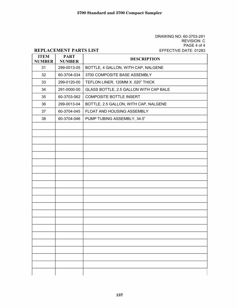
3700 Standard and 3700 Compact Sampler
137
DRAWING NO: 60-3703-261 REVISION: C PAGE 4 of 4
REPLACEMENT PARTS LIST EFFECTIVE DATE: 01283ITEM
NUMBER PART
NUMBER DESCRIPTION
31 299-0013-05 BOTTLE, 4 GALLON, WITH CAP, NALGENE
32 60-3704-034 3700 COMPOSITE BASE ASSEMBLY
33 299-0120-00 TEFLON LINER, 120MM X .020” THICK
34 291-0000-00 GLASS BOTTLE, 2.5 GALLON WITH CAP BALE
35 60-3703-062 COMPOSITE BOTTLE INSERT
36 299-0013-04 BOTTLE, 2.5 GALLON, WITH CAP, NALGENE
37 60-3704-045 FLOAT AND HOUSING ASSEMBLY
38 60-3704-046 PUMP TUBING ASSEMBLY, 34.5”
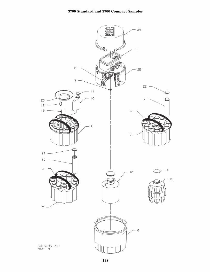
3700 Standard and 3700 Compact Sampler
138
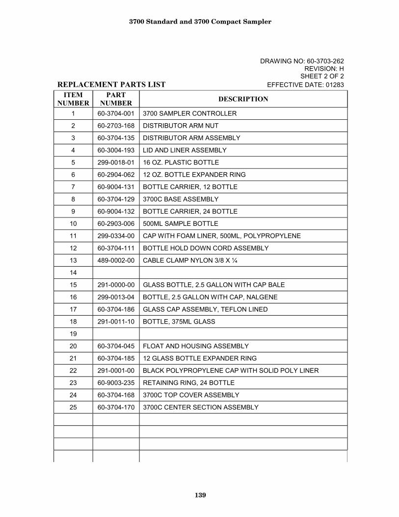
3700 Standard and 3700 Compact Sampler
139
DRAWING NO: 60-3703-262 REVISION: H
SHEET 2 OF 2 REPLACEMENT PARTS LIST EFFECTIVE DATE: 01283
ITEM NUMBER
PART NUMBER DESCRIPTION
1 60-3704-001 3700 SAMPLER CONTROLLER
2 60-2703-168 DISTRIBUTOR ARM NUT
3 60-3704-135 DISTRIBUTOR ARM ASSEMBLY
4 60-3004-193 LID AND LINER ASSEMBLY
5 299-0018-01 16 OZ. PLASTIC BOTTLE
6 60-2904-062 12 OZ. BOTTLE EXPANDER RING
7 60-9004-131 BOTTLE CARRIER, 12 BOTTLE
8 60-3704-129 3700C BASE ASSEMBLY
9 60-9004-132 BOTTLE CARRIER, 24 BOTTLE
10 60-2903-006 500ML SAMPLE BOTTLE
11 299-0334-00 CAP WITH FOAM LINER, 500ML, POLYPROPYLENE
12 60-3704-111 BOTTLE HOLD DOWN CORD ASSEMBLY
13 489-0002-00 CABLE CLAMP NYLON 3/8 X ¼
14
15 291-0000-00 GLASS BOTTLE, 2.5 GALLON WITH CAP BALE
16 299-0013-04 BOTTLE, 2.5 GALLON WITH CAP, NALGENE
17 60-3704-186 GLASS CAP ASSEMBLY, TEFLON LINED
18 291-0011-10 BOTTLE, 375ML GLASS
19
20 60-3704-045 FLOAT AND HOUSING ASSEMBLY
21 60-3704-185 12 GLASS BOTTLE EXPANDER RING
22 291-0001-00 BLACK POLYPROPYLENE CAP WITH SOLID POLY LINER
23 60-9003-235 RETAINING RING, 24 BOTTLE
24 60-3704-168 3700C TOP COVER ASSEMBLY
25 60-3704-170 3700C CENTER SECTION ASSEMBLY
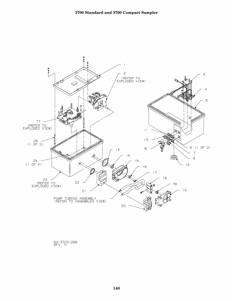
3700 Standard and 3700 Compact Sampler
140

3700 Standard and 3700 Compact Sampler
141
DRAWING NO: 60-3703-268 REVISION: D
SHEET 2 OF 8 REPLACEMENT PARTS LIST EFFECTIVE DATE: 01283
ITEM NUMBER
PART NUMBER DESCRIPTION
1 60-3703-252 DESICCANT TRAY, CE 2 60-3704-154 PUMP GEAR CASE ASSEMBLY, CE 3 60-3704-151 CIRCUIT BOARD ASSEMBLY, POWER SUPPLY CONNECTIONS 4 60-3704-156 BACK PLATE ASSEMBLY WITH GASKET, CE 5 60-3704-089 CONTROL BOX MODIFICATION ASSEMBLY 6 60-1473-057 SEAL GASKET, 6 PIN AMP 7 140-1006-00 PLUG, PANEL MOUNT, 6 PIN 8 149-1001-00 DUST COVER #14 9 60-3704-091 PRINTER CONNECTOR ASSEMBLY 10 140-1002-01 PLUG, PANEL MOUNT, 2 PIN 11 60-1393-082 SEAL GASKET, 2 PIN AMP 12 202-9999-04 LIP SEAL, 1.000 ID X 1.500 OD 13 202-1001-35 O RING, 1.925 ID, .103 CROSS SECTION, BUNA-N 14 202-9999-03 LIP SEAL, .375 ID X .750 OD 15 60-3704-019 PUMP HOUSING ASSEMBLY, INSIDE 16 60-3703-012 PUMP HOUSING BUSHING 17 231-9145-12 SCREW, MACHINE, 8-32 X ¾, SELF SEAL, STAINLESS STEEL 18 60-2704-019 PUMP ROTOR ASSEMBLY 19 60-3704-017 PUMP HOUSING ASSEMBLY, OUTSIDE (INCLUDES ITEM 78) 20 60-3704-021 DETECTOR LID ASSEMBLY 21 60-3704-022 DETECTOR BASE ASSEMBLY 22 202-4012-37 O RING, 1.237 ID, .103 CROSS SECTION 23 60-3704-152 CONTROL BOX SUB-ASSEMBLY, CE 24 231-0195-08 SCREW, MACHINE, 8-32 X ½, SELF-SEAL, STAINLESS STEEL 25 60-2703-170 STANDOFF, 6-32 X .25 HEX X 3.00 LONG, MALE, SST 77 60-3704-173 DISTRIBUTOR DRIVE ASSEMBLY, CE 78 60-3703-278 PUMP HOUSING BUSHING
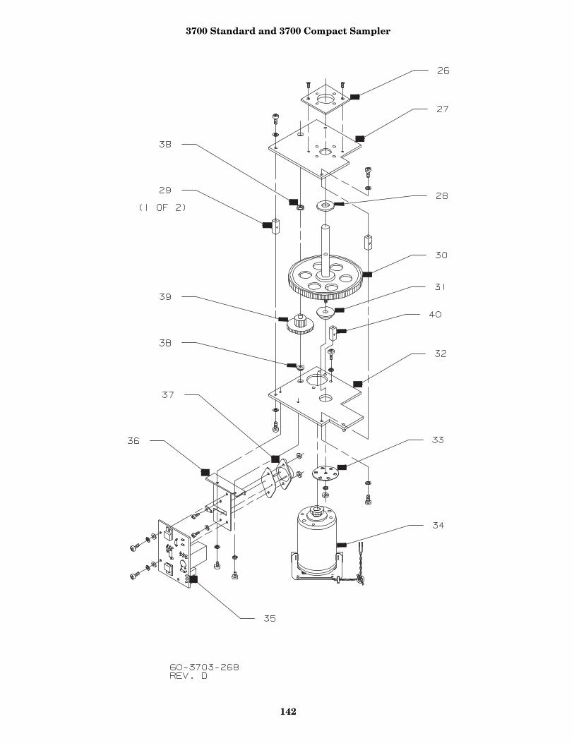
3700 Standard and 3700 Compact Sampler
142
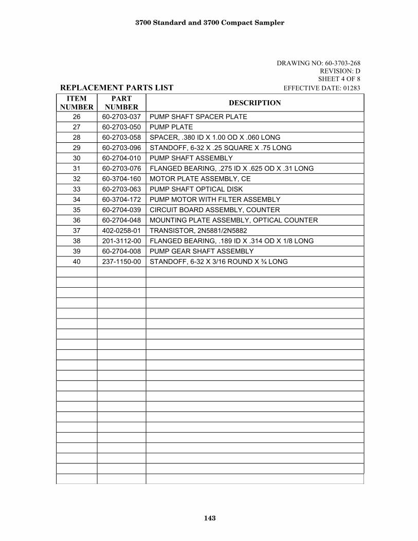
3700 Standard and 3700 Compact Sampler
143
DRAWING NO: 60-3703-268 REVISION: D
SHEET 4 OF 8 REPLACEMENT PARTS LIST EFFECTIVE DATE: 01283
ITEM NUMBER
PART NUMBER DESCRIPTION
26 60-2703-037 PUMP SHAFT SPACER PLATE 27 60-2703-050 PUMP PLATE 28 60-2703-058 SPACER, .380 ID X 1.00 OD X .060 LONG 29 60-2703-096 STANDOFF, 6-32 X .25 SQUARE X .75 LONG 30 60-2704-010 PUMP SHAFT ASSEMBLY 31 60-2703-076 FLANGED BEARING, .275 ID X .625 OD X .31 LONG 32 60-3704-160 MOTOR PLATE ASSEMBLY, CE 33 60-2703-063 PUMP SHAFT OPTICAL DISK 34 60-3704-172 PUMP MOTOR WITH FILTER ASSEMBLY 35 60-2704-039 CIRCUIT BOARD ASSEMBLY, COUNTER 36 60-2704-048 MOUNTING PLATE ASSEMBLY, OPTICAL COUNTER 37 402-0258-01 TRANSISTOR, 2N5881/2N5882 38 201-3112-00 FLANGED BEARING, .189 ID X .314 OD X 1/8 LONG 39 60-2704-008 PUMP GEAR SHAFT ASSEMBLY 40 237-1150-00 STANDOFF, 6-32 X 3/16 ROUND X ¾ LONG
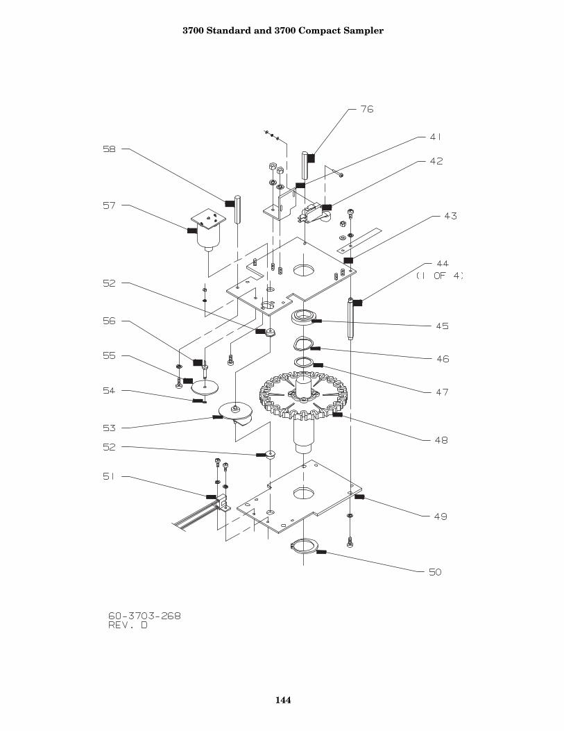
3700 Standard and 3700 Compact Sampler
144
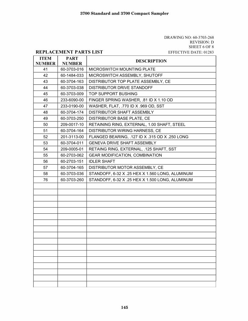
3700 Standard and 3700 Compact Sampler
145
DRAWING NO: 60-3703-268 REVISION: D
SHEET 6 OF 8 REPLACEMENT PARTS LIST EFFECTIVE DATE: 01283
ITEM NUMBER
PART NUMBER DESCRIPTION
41 60-3703-016 MICROSWITCH MOUNTING PLATE 42 60-1484-033 MICROSWITCH ASSEMBLY, SHUTOFF 43 60-3704-163 DISTRIBUTOR TOP PLATE ASSEMBLY, CE 44 60-3703-038 DISTRIBUTOR DRIVE STANDOFF 45 60-3703-009 TOP SUPPORT BUSHING 46 233-6090-00 FINGER SPRING WASHER, .81 ID X 1.10 OD 47 233-0190-00 WASHER, FLAT, .770 ID X .969 OD, SST 48 60-3704-174 DISTRIBUTOR SHAFT ASSEMBLY 49 60-3703-250 DISTRIBUTOR BASE PLATE, CE 50 209-0017-10 RETAINING RING, EXTERNAL, 1.00 SHAFT, STEEL 51 60-3704-164 DISTRIBUTOR WIRING HARNESS, CE 52 201-3113-00 FLANGED BEARING, .127 ID X .315 OD X .250 LONG 53 60-3704-011 GENEVA DRIVE SHAFT ASSEMBLY 54 209-0005-01 RETAING RING, EXTERNAL, .125 SHAFT, SST 55 60-2703-062 GEAR MODIFICATION, COMBINATION 56 60-2703-151 IDLER SHAFT 57 60-3704-165 DISTRIBUTOR MOTOR ASSEMBLY, CE 58 60-3703-036 STANDOFF, 6-32 X .25 HEX X 1.560 LONG, ALUMINUM 76 60-3703-260 STANDOFF, 6-32 X .25 HEX X 1.500 LONG, ALUMINUM
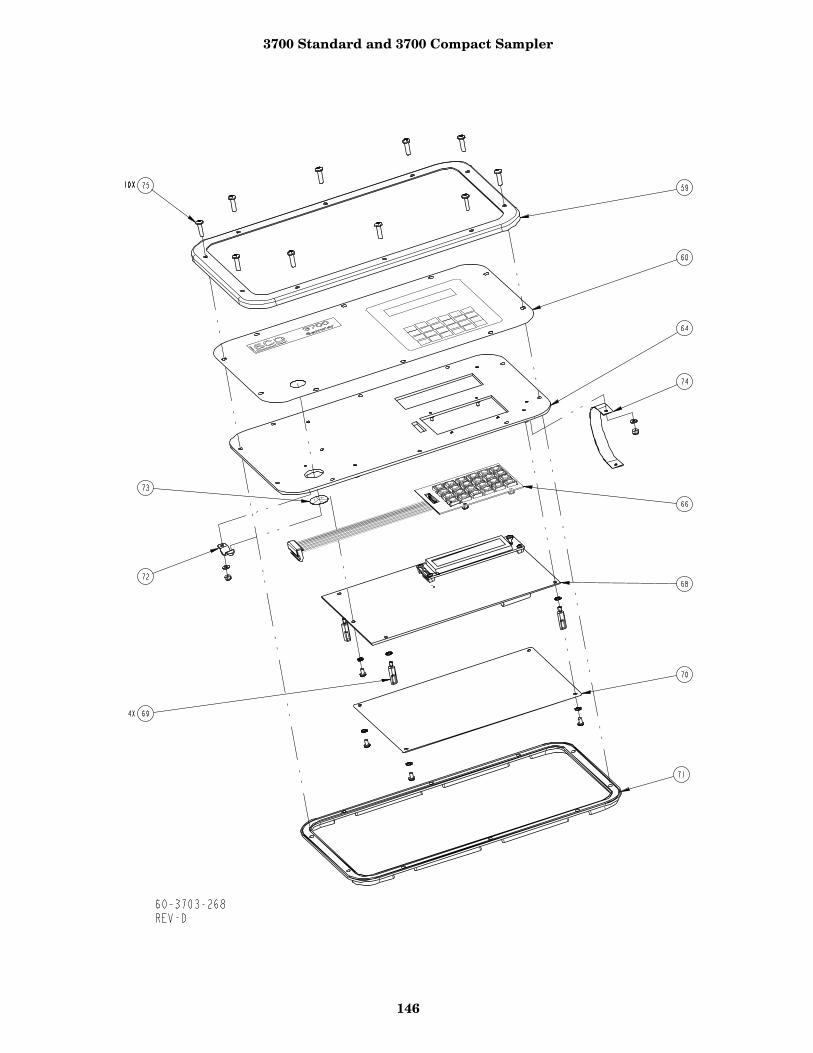
3700 Standard and 3700 Compact Sampler
146
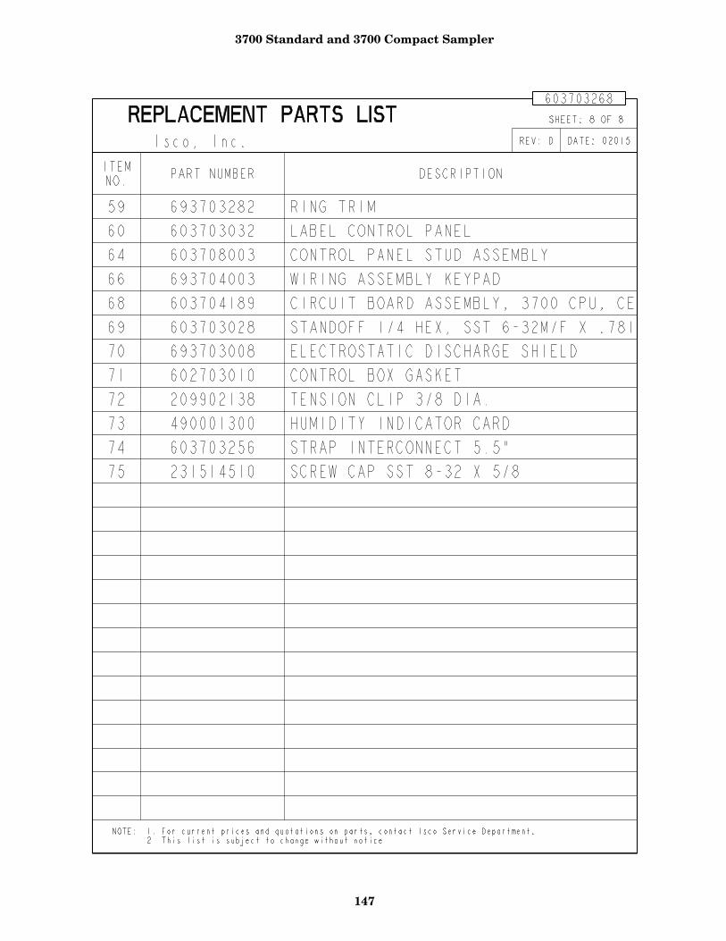
3700 Standard and 3700 Compact Sampler
147
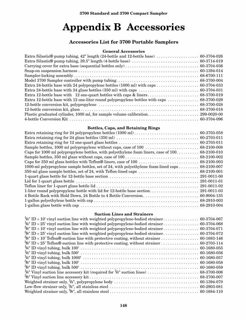
3700 Standard and 3700 Compact Sampler
148
Appendix B AccessoriesAccessories List for 3700 Portable Samplers
General AccessoriesExtra Silastic® pump tubing, 42" length (24-bottle and 12-bottle base) . . . . . . . . . . . . . . . . . . . 60-3704-026Extra Silastic® pump tubing, 39.5" length (4-bottle base) . . . . . . . . . . . . . . . . . . . . . . . . . . . . . . 60-3714-019Carrying cover for extra base (sequential bottles only) . . . . . . . . . . . . . . . . . . . . . . . . . . . . . . . . . 60-3704-036Snap-on suspension harness . . . . . . . . . . . . . . . . . . . . . . . . . . . . . . . . . . . . . . . . . . . . . . . . . . . . . . 60-1394-014Sampler-locking assembly . . . . . . . . . . . . . . . . . . . . . . . . . . . . . . . . . . . . . . . . . . . . . . . . . . . . . . . . 68-6700-111Model 3700 Sampler controller with pump tubing. . . . . . . . . . . . . . . . . . . . . . . . . . . . . . . . . . . . . 68-3700-004Extra 24-bottle base with 24 polypropylene bottles (1000 ml) with caps . . . . . . . . . . . . . . . . . . . 60-3704-033Extra 24-bottle base with 24 glass bottles (350 ml) with caps . . . . . . . . . . . . . . . . . . . . . . . . . . . 60-3704-031Extra 12-bottle base with 12 one-quart bottles with caps & liners . . . . . . . . . . . . . . . . . . . . . . . 68-3700-019Extra 12-bottle base with 12 one-liter round polypropylene bottles with caps . . . . . . . . . . . . . . 68-3700-02912-bottle conversion kit, polypropylene . . . . . . . . . . . . . . . . . . . . . . . . . . . . . . . . . . . . . . . . . . . . . 68-3700-02812-bottle conversion kit, glass . . . . . . . . . . . . . . . . . . . . . . . . . . . . . . . . . . . . . . . . . . . . . . . . . . . . . 68-3700-018Plastic graduated cylinder, 1000 ml, for sample volume calibration. . . . . . . . . . . . . . . . . . . . . . . 299-0020-004-bottle Conversion Kit . . . . . . . . . . . . . . . . . . . . . . . . . . . . . . . . . . . . . . . . . . . . . . . . . . . . . . . . . . 60-3704-096
Bottles, Caps, and Retaining RingsExtra retaining ring for 24 polypropylene bottles (1000 ml) . . . . . . . . . . . . . . . . . . . . . . . . . . . . . 60-3703-058Extra retaining ring for 24 glass bottles (350 ml) . . . . . . . . . . . . . . . . . . . . . . . . . . . . . . . . . . . . . 60-2703-011Extra retaining ring for 12 one-quart glass bottles . . . . . . . . . . . . . . . . . . . . . . . . . . . . . . . . . . . . 60-2703-011Sample bottles, 1000 ml polypropylene without caps, case of 100 . . . . . . . . . . . . . . . . . . . . . . . . 68-2100-008Caps for 1000 ml polypropylene bottles, with polyethylene foam liners, case of 100. . . . . . . . . . 68-2100-010Sample bottles, 350 ml glass without caps, case of 100 . . . . . . . . . . . . . . . . . . . . . . . . . . . . . . . . . 68-2100-002Caps for 350 ml glass bottles with Teflon® liners, case of 100 . . . . . . . . . . . . . . . . . . . . . . . . . . . 68-2100-0031000-ml polypropylene sample bottles, set of 24, with polyethylene foam-lined caps . . . . . . . . . 68-2100-007350-ml glass sample bottles, set of 24, with Teflon-lined caps . . . . . . . . . . . . . . . . . . . . . . . . . . . 68-2100-0011-quart glass bottle for 12-bottle base section . . . . . . . . . . . . . . . . . . . . . . . . . . . . . . . . . . . . . . . . 291-0011-00Lid for 1-quart glass bottle . . . . . . . . . . . . . . . . . . . . . . . . . . . . . . . . . . . . . . . . . . . . . . . . . . . . . . . 291-0011-01Teflon liner for 1-quart glass bottle lid . . . . . . . . . . . . . . . . . . . . . . . . . . . . . . . . . . . . . . . . . . . . . . 291-0011-021-liter round polypropylene bottle with lid for 12-bottle base section. . . . . . . . . . . . . . . . . . . . . . 291-0011-034 Bottle Rack with Hold Down, 24 Bottle to 4 Bottle Conversion. . . . . . . . . . . . . . . . . . . . . . . . . 60-9004-1351-gallon polyethylene bottle with cap . . . . . . . . . . . . . . . . . . . . . . . . . . . . . . . . . . . . . . . . . . . . . . . 68-2910-0031-gallon glass bottle with cap . . . . . . . . . . . . . . . . . . . . . . . . . . . . . . . . . . . . . . . . . . . . . . . . . . . . . 68-2910-004
Suction Lines and Strainers1/4" ID × 10' vinyl suction line with weighted polypropylene-bodied strainer . . . . . . . . . . . . . . . . 60-3704-0671/4" ID × 25' vinyl suction line with weighted polypropylene-bodied strainer . . . . . . . . . . . . . . . . 60-3704-0683/8" ID × 10' vinyl suction line with weighted polypropylene-bodied strainer . . . . . . . . . . . . . . . . 60-3704-0713/8" ID × 25' vinyl suction line with weighted polypropylene-bodied strainer . . . . . . . . . . . . . . . . 60-3704-0723/8" ID × 10' Teflon® suction line with protective coating, without strainer . . . . . . . . . . . . . . . . . 60-1683-1463/8" ID × 25' Teflon® suction line with protective coating, without strainer . . . . . . . . . . . . . . . . . 60-2703-1141/4" ID vinyl tubing, bulk 100' . . . . . . . . . . . . . . . . . . . . . . . . . . . . . . . . . . . . . . . . . . . . . . . . . . . . . 60-1680-0551/4" ID vinyl tubing, bulk 500' . . . . . . . . . . . . . . . . . . . . . . . . . . . . . . . . . . . . . . . . . . . . . . . . . . . . . 60-1680-0561/4" ID vinyl tubing, bulk 1000' . . . . . . . . . . . . . . . . . . . . . . . . . . . . . . . . . . . . . . . . . . . . . . . . . . . . 60-1680-0573/8" ID vinyl tubing, bulk 100' . . . . . . . . . . . . . . . . . . . . . . . . . . . . . . . . . . . . . . . . . . . . . . . . . . . . . 60-1680-0583/8" ID vinyl tubing, bulk 500' . . . . . . . . . . . . . . . . . . . . . . . . . . . . . . . . . . . . . . . . . . . . . . . . . . . . . 60-1680-0591/4" Vinyl suction line accessory kit (required for 1/4" suction lines) . . . . . . . . . . . . . . . . . . . . . . . 68-3700-0063/8" Vinyl suction line accessory kit . . . . . . . . . . . . . . . . . . . . . . . . . . . . . . . . . . . . . . . . . . . . . . . . . 68-3700-007Weighted strainer only, 1/4", polypropylene body . . . . . . . . . . . . . . . . . . . . . . . . . . . . . . . . . . . . . . 60-1394-070Low-flow strainer only, 1/4", all stainless steel . . . . . . . . . . . . . . . . . . . . . . . . . . . . . . . . . . . . . . . . 60-2903-081Weighted strainer only, 3/8", all stainless steel . . . . . . . . . . . . . . . . . . . . . . . . . . . . . . . . . . . . . . . . 60-1684-110

3700 Standard and 3700 Compact Sampler
149
Weighted strainer only, 3/8", polypropylene body . . . . . . . . . . . . . . . . . . . . . . . . . . . . . . . . . . . . . . 60-1394-071Low-flow strainer only, 3/8", all stainless steel
(not recommended for use with Teflon® suction line) . . . . . . . . . . . . . . . . . . . . . . . . . . . . 60-2903-079Weighted strainer only, 3/8", all plastic . . . . . . . . . . . . . . . . . . . . . . . . . . . . . . . . . . . . . . . . . . . . . . 60-3704-066Extra Silastic pump tubing, bulk 15' length. . . . . . . . . . . . . . . . . . . . . . . . . . . . . . . . . . . . . . . . . . 68-1680-061Extra Silastic pump tubing, bulk 50' length. . . . . . . . . . . . . . . . . . . . . . . . . . . . . . . . . . . . . . . . . . 68-1680-065
Power SourcesModel 913 High Capacity Power Pack (120-volt) . . . . . . . . . . . . . . . . . . . . . . . . . . . . . . . . . . . . . . 60-1684-088Model 914 Battery-Backed Power Pack (120-volt) . . . . . . . . . . . . . . . . . . . . . . . . . . . . . . . . . . . . . 60-3004-130Model 923 High Capacity Power Pack (240-volt) . . . . . . . . . . . . . . . . . . . . . . . . . . . . . . . . . . . . . . 60-1684-093Model 924 Battery-Backed Power Pack (240-volt) . . . . . . . . . . . . . . . . . . . . . . . . . . . . . . . . . . . . . 60-3004-160Model 934 Nickel-Cadmium Battery. . . . . . . . . . . . . . . . . . . . . . . . . . . . . . . . . . . . . . . . . . . . . . . . 60-1684-040Model 946 Lead-Acid Battery . . . . . . . . . . . . . . . . . . . . . . . . . . . . . . . . . . . . . . . . . . . . . . . . . . . . . 60-3004-106Model 948 45-Amp-Hour Battery . . . . . . . . . . . . . . . . . . . . . . . . . . . . . . . . . . . . . . . . . . . . . . . . . . 68-3000-948Portable 12-volt DC, 6-Amp Battery Charger for 948 Battery . . . . . . . . . . . . . . . . . . . . . . . . . . . 341-0118-12Model 961 Battery Charger (120-volt) . . . . . . . . . . . . . . . . . . . . . . . . . . . . . . . . . . . . . . . . . . . . . . 60-3004-059Model 965 Five Station Battery Charger . . . . . . . . . . . . . . . . . . . . . . . . . . . . . . . . . . . . . . . . . . . . 68-3000-965Model 954 Solar Panel Battery Charger . . . . . . . . . . . . . . . . . . . . . . . . . . . . . . . . . . . . . . . . . . . . . 68-3000-027Additional Solar Panel . . . . . . . . . . . . . . . . . . . . . . . . . . . . . . . . . . . . . . . . . . . . . . . . . . . . . . . . . . . 68-3000-028Solar Panel Cable (25-foot Length) . . . . . . . . . . . . . . . . . . . . . . . . . . . . . . . . . . . . . . . . . . . . . . . . . 60-3004-097Solar Panel “Y” Cable. . . . . . . . . . . . . . . . . . . . . . . . . . . . . . . . . . . . . . . . . . . . . . . . . . . . . . . . . . . . 60-3004-098Solar Panel/Interr. Extension Cable . . . . . . . . . . . . . . . . . . . . . . . . . . . . . . . . . . . . . . . . . . . . . . . . 60-2544-028Connect cable, for external 12 VDC power source; terminates in
heavy duty battery clips . . . . . . . . . . . . . . . . . . . . . . . . . . . . . . . . . . . . . . . . . . . . . . . . . . . 60-1394-023
Interfacing EquipmentModel 1640 Liquid Level Actuator . . . . . . . . . . . . . . . . . . . . . . . . . . . . . . . . . . . . . . . . . . . . . . . . . 60-1644-000Extra Instruction Manual, Model 1640. . . . . . . . . . . . . . . . . . . . . . . . . . . . . . . . . . . . . . . . . . . . . . 60-1644-009Connect cable, 25', Isco sampler to Isco flow meter . . . . . . . . . . . . . . . . . . . . . . . . . . . . . . . . . . . . 60-3004-107Connector only, without cable, for use with non-Isco flow meters
with an isolated contact closure proportional to flow . . . . . . . . . . . . . . . . . . . . . . . . . . . . 68-1680-060Same as above, with 22' cable terminating in two wires . . . . . . . . . . . . . . . . . . . . . . . . . . . . . . . . 60-1394-077Type A Interface (converts pulse duration flow meter output proportional
to flow into pulses acceptable to Isco samplers) . . . . . . . . . . . . . . . . . . . . . . . . . . . . . . . . 60-1784-0074-20 mA Sampler Input Interface (converts analog signal flow meter output
as specified by user into pulses acceptable to Isco samplers) . . . . . . . . . . . . . . . . . . . . . . 60-3704-037Isco Field Printer . . . . . . . . . . . . . . . . . . . . . . . . . . . . . . . . . . . . . . . . . . . . . . . . . . . . . . . . . . . . . . . 60-3774-001FLOWLINK 3® Software with manual . . . . . . . . . . . . . . . . . . . . . . . . . . . . . . . . . . . . . . . . . . . . . . 68-2544-043SAMPLINK Sampler Interrogation Software with manual . . . . . . . . . . . . . . . . . . . . . . . . . . . . . 60-3774-013Interrogator communications line kit - 9-pin (connects laptop computer
with a 9-pin serial port to sampler) . . . . . . . . . . . . . . . . . . . . . . . . . . . . . . . . . . . . . . . . . . 60-2544-044Interrogator communications line kit - 25-pin (connects laptop computer
with 25-pin serial port to sampler) . . . . . . . . . . . . . . . . . . . . . . . . . . . . . . . . . . . . . . . . . . . 60-2544-040Master/Slave Interconnect Cable, 10' . . . . . . . . . . . . . . . . . . . . . . . . . . . . . . . . . . . . . . . . . . . . . . . 60-3704-0653700 Master/Slave to Flow Meter Cable (Connects two 3700 Samplers as a
master and slave to a flow meter . . . . . . . . . . . . . . . . . . . . . . . . . . . . . . . . . . . . . . . . . . . . 60-3704-080

3700 Standard and 3700 Compact Sampler
150
Appendix C Display IndexNoteTo access the display number, press the stop key while the sampler displays the screen in question. The display numbers are available in the Standby and Program states.
Figure 44 Time Line
Table 13 Display Index
This display appears after you press the ENTER/PROGRAM key while in standby. Select “PROGRAM” to accessthe program sequence. Select “CONFIGURE” to access the configure sequence.
Display 1[PROGRAM, CONFIGURE]
SAMPLER
This informational display appears when you stop the pump with the STOP key after pressing the PUMP FOR-WARD key. It reports the number of pump counts detected while the pump was in operation. Exit this displayby pressing any key except STOP and ON/OFF.
Display 3 ----- COUNTS FORWARD
This informational display appears when you stop the pump with the STOP key after having pressed the PUMP
REVERSE key. It reports the number of pump counts detected while the pump was in operation. Exit this dis-play by pressing any key except STOP and ON/OFF.
Display 3 ----- COUNTS REVERSE
This display appears after you select “PROGRAM” in Display #1. Select “TIME” for time-paced sampling,“FLOW” for flow-paced sampling.
Display 10[TIME, FLOW]
PACED SAMPLING
This display appears only in the extended programming mode and follows Display #10 when you have selected“TIME.” Select “UNIFORM” for uniform time intervals, “NONUNIFORM” for nonuniform time intervals.
Display 11[UNIFORM, NONUNIFORM]
TIME INTERVALS
This display appears after you select “PROGRAM” in Display #1. It appears only when the sampler is config-ured for the extended programming mode and for 4, 12, or 24 bottles with the 3700 Portable and 12 or 24 bot-tles with the 3700 Compact. Select “TIME” for time-paced sampling. Select “FLOW” for flow-paced sampling,and “STORM” for storm sampling.
Display 12[TIME, FLOW, STORM]
PACED SAMPLING
Start Time
6 intervals of 20 minutes 9 intervals of 30 minutes 3 intervals of45 minutes
Interval
EventNo.
2020 20 20 20 20 30 30 30 30 30 30 30 30 30 45 45 45
1 2 3 4 5 6 7 8 9 10 11 12 13 14 15 16 17 18 19
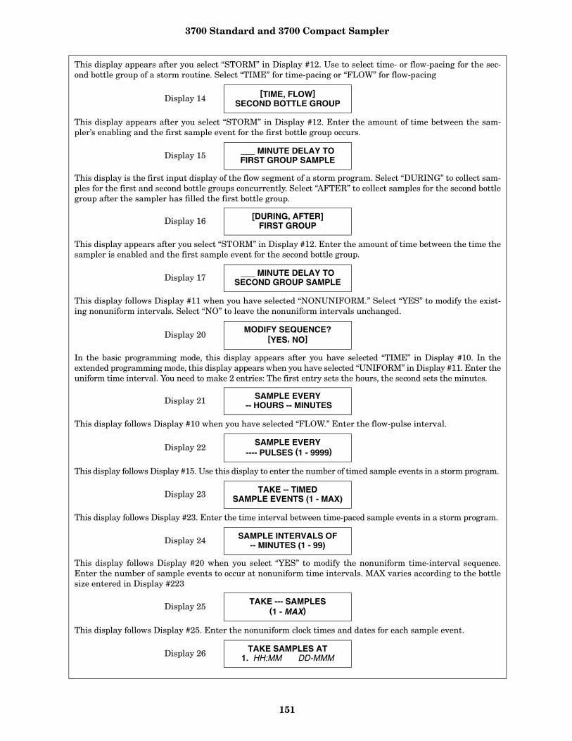
3700 Standard and 3700 Compact Sampler
151
This display appears after you select “STORM” in Display #12. Use to select time- or flow-pacing for the sec-ond bottle group of a storm routine. Select “TIME” for time-pacing or “FLOW” for flow-pacing
Display 14[TIME, FLOW]
SECOND BOTTLE GROUP
This display appears after you select “STORM” in Display #12. Enter the amount of time between the sam-pler’s enabling and the first sample event for the first bottle group occurs.
Display 15 ___ MINUTE DELAY TOFIRST GROUP SAMPLE
This display is the first input display of the flow segment of a storm program. Select “DURING” to collect sam-ples for the first and second bottle groups concurrently. Select “AFTER” to collect samples for the second bottlegroup after the sampler has filled the first bottle group.
Display 16 [DURING, AFTER]FIRST GROUP
This display appears after you select “STORM” in Display #12. Enter the amount of time between the time thesampler is enabled and the first sample event for the second bottle group.
Display 17 ___ MINUTE DELAY TOSECOND GROUP SAMPLE
This display follows Display #11 when you have selected “NONUNIFORM.” Select “YES” to modify the exist-ing nonuniform intervals. Select “NO” to leave the nonuniform intervals unchanged.
Display 20MODIFY SEQUENCE?
[YES, NO]
In the basic programming mode, this display appears after you have selected “TIME” in Display #10. In theextended programming mode, this display appears when you have selected “UNIFORM” in Display #11. Enter theuniform time interval. You need to make 2 entries: The first entry sets the hours, the second sets the minutes.
Display 21 SAMPLE EVERY -- HOURS -- MINUTES
This display follows Display #10 when you have selected “FLOW.” Enter the flow-pulse interval.
Display 22SAMPLE EVERY
---- PULSES (1 - 9999)
This display follows Display #15. Use this display to enter the number of timed sample events in a storm program.
Display 23 TAKE -- TIMEDSAMPLE EVENTS (1 - MAX)
This display follows Display #23. Enter the time interval between time-paced sample events in a storm program.
Display 24 SAMPLE INTERVALS OF-- MINUTES (1 - 99)
This display follows Display #20 when you select “YES” to modify the nonuniform time-interval sequence.Enter the number of sample events to occur at nonuniform time intervals. MAX varies according to the bottlesize entered in Display #223
Display 25 TAKE --- SAMPLES (1 - MAX)
This display follows Display #25. Enter the nonuniform clock times and dates for each sample event.
Display 26 TAKE SAMPLES AT 1. HH:MM DD-MMM

3700 Standard and 3700 Compact Sampler
152
Enter the number of samples to be taken at each interval. The total quantity you enter will be 1 fewer thanthe total number of samples, because the first sample, taken at the start time, counts as 1. For example, if youwant to take 19 samples (the first 6 at 20-minute intervals, the next 9 at 30-minute intervals, and the remain-ing 3 at 45-minute intervals), first enter a quantity of 6 at 20 minutes, 9 at 30 minutes, and 3 at 45 minutes.Figure 44 shows a time line for the sampling routine.
Display 27 QUANTITY AT INTERVAL1. -- AT --- MINUTES
This display appears for samplers configured for 2, 8, and 24 bottles (Display #s 221 or 222) with the 3700 Por-table or 24 for the 3700 Compact (Display #22X). It does not appear for samplers configured for a single bottle.In the basic programming mode, it follows Display #36. In the extended programming mode, it follows one ofthe four sample-interval entry displays (Display #s 21, 22, 26, 27). Enter the number of bottles to receive asample volume at each sample event.
Display 30 -- BOTTLES PERSAMPLE EVENT (1 - MAX)
In the basic programming mode, this display appears when you have selected “SAMPLES PER BOTTLE” inDisplay #36. In the extended programming mode, it appears when the sampler is configured for 2, 8, or 24 bot-tles and there is only one bottle set. Enter the number of samples you want deposited in each bottle.
Display 31-- SAMPLES PERBOTTLE (1 - MAX)
Select “YES” if you want the routine to perform bottles-per-sample or samples-per-bottle multiplexing. Select“NO” if you want the routine to perform sequential sampling.
Display 35MULTIPLEX SAMPLES?
[YES, NO]
This display appears when you have selected “YES” in Display #35. Select “BOTTLES PER SAMPLE” if youwant the sampler to perform bottles-per-sample multiplexing. Select “SAMPLES PER BOTTLE” if you wantthe sampler to perform samples-per-bottle multiplexing.
Display 36[BOTTLES PER SAMPLE,SAMPLES PER BOTTLE]
This display appears only in the extended programming mode when you have set the number of bottles persample event to “1” in Display #30. Select “TIME” if you want the bottles to be switched after a specified periodof time. Select “SAMPLES” if you want the bottles to be switched after a specified number of samples havebeen placed in a bottle. We recommend using “SAMPLES” for time-paced sampling routines.
Display 40 CHANGE BOTTLES BASEDON [TIME, SAMPLES]
This display appears when the number of bottles per sample event is set to a number greater than one andless than half the number of bottles in the tub. Select “TIME” to switch bottle sets after a specified period oftime. Select “SAMPLES/BTL” to switch bottle sets after a specified number of samples have been placed in aset of bottles. Isco recommends using “SAMPLES/BTL” for time-paced sampling routines.
Display 41CHANGE SETS BASED
ON [TIME, SAMPLES/BTL]
This display appears if you select “TIME” in Display #40. Enter the amount of time each bottle is to receivesamples.
Display 42 CHANGE BOTTLES EVERY-- HOURS -- MINUTES

3700 Standard and 3700 Compact Sampler
153
This display appears if you select “TIME” in Display #41. Enter the amount of time each bottle set receivessamples.
Display 43 CHANGE SETS EVERY-- HOURS -- MINUTES
This display appears after you select “SAMPLES” in Display #40. Enter the number of samples each bottlereceives.
Display 44 CHANGE BOTTLES EVERY-- SAMPLES
This display appears after you select “SAMPLES/BTL” in Display #41. Enter the number of samples each bot-tle set is to receive.
Display 45 CHANGE SETS EVERY-- SAMPLES
This display appears when you select “yes”” in Display #95. Enter the time of the first bottle switch. Theremaining bottle changes will occur according to settings entered in Display #42. The display will also appearif you have started the routine after the programmed switch time.
Display 46 FIRST BOTTLE CHANGE AT HH:MM MM/DD
This display appears when you select “YES” in Display #95. Enter the time of the first-bottle set switch. Theremaining bottle-set changes will occur according to settings entered in Display #43. The display will alsoappear if you start the routine after the programmed switch time.
Display 47 FIRST SET CHANGE ATHH:MM MM/DD
This display appears when the sampler is configured for 2-, 4-, 8-, 12-, or 24- bottle configurations under uni-form time, flow, or nonuniform time modes of sample pacing. Select “YES” to sample continuously. Select “NO”to stop the sampling routine after the last set of bottles has been filled.
Display 48SAMPLE CONTINUOUSLY?
[YES, NO]
Enter the size of the sample volume. MAX will vary according to the number of samples per bottle and bottle size.
Display 50SAMPLE VOLUMES OF--- ml EACH (10 - MAX )
This display appears when you have configured the controller for composite sampling by selecting “1” in Dis-play #221 or #222. Enter the number of composite samples. An entry of “0” instructs the sampler to take sam-ples until a float shut-off terminates the sampling routine.
Display 60 --- COMPOSITESAMPLES (0 - MAX)
This display appears when you select “YES” in Display #242 or select “DISABLE” in Display #240. Enter themeasured suction head. MAX will be the smaller of the suction line length or “20.”
Display 70 SUCTION HEAD OF-- FEET (1 - MAX)
This display appears in the program sequence when you have selected “ENABLE” in Display #290. Select“YES” to use the calibration sequence, “NO” to omit the calibration sequence.
Display 80CALIBRATE SAMPLEVOLUME? [YES, NO]
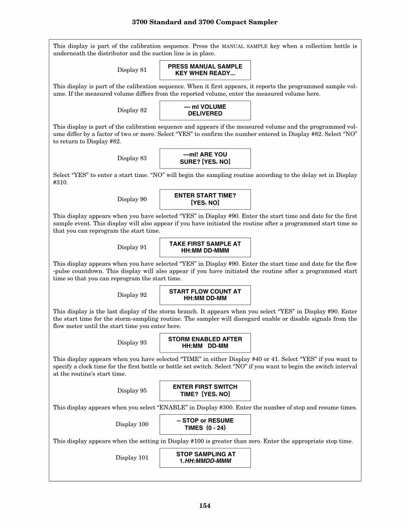
3700 Standard and 3700 Compact Sampler
154
This display is part of the calibration sequence. Press the MANUAL SAMPLE key when a collection bottle isunderneath the distributor and the suction line is in place.
Display 81 PRESS MANUAL SAMPLEKEY WHEN READY...
This display is part of the calibration sequence. When it first appears, it reports the programmed sample vol-ume. If the measured volume differs from the reported volume, enter the measured volume here.
Display 82 --- ml VOLUMEDELIVERED
This display is part of the calibration sequence and appears if the measured volume and the programmed vol-ume differ by a factor of two or more. Select “YES” to confirm the number entered in Display #82. Select “NO”to return to Display #82.
Display 83 ---ml! ARE YOUSURE? [YES, NO]
Select “YES” to enter a start time. “NO” will begin the sampling routine according to the delay set in Display#310.
Display 90 ENTER START TIME?[YES, NO]
This display appears when you have selected “YES” in Display #90. Enter the start time and date for the firstsample event. This display will also appear if you have initiated the routine after a programmed start time sothat you can reprogram the start time.
Display 91 TAKE FIRST SAMPLE ATHH:MM DD-MMM
This display appears when you have selected “YES” in Display #90. Enter the start time and date for the flow-pulse countdown. This display will also appear if you have initiated the routine after a programmed starttime so that you can reprogram the start time.
Display 92 START FLOW COUNT ATHH:MM DD-MM
This display is the last display of the storm branch. It appears when you select “YES” in Display #90. Enterthe start time for the storm-sampling routine. The sampler will disregard enable or disable signals from theflow meter until the start time you enter here.
Display 93 STORM ENABLED AFTERHH:MM DD-MM
This display appears when you have selected “TIME” in either Display #40 or 41. Select “YES” if you want tospecify a clock time for the first bottle or bottle set switch. Select “NO” if you want to begin the switch intervalat the routine's start time.
Display 95ENTER FIRST SWITCH
TIME? [YES, NO]
This display appears when you select “ENABLE” in Display #300. Enter the number of stop and resume times.
Display 100 -- STOP or RESUMETIMES (0 - 24)
This display appears when the setting in Display #100 is greater than zero. Enter the appropriate stop time.
Display 101 STOP SAMPLING AT1.HH:MMDD-MMM
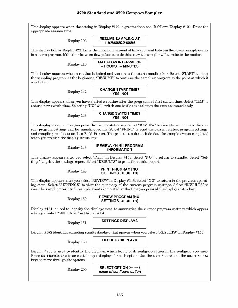
3700 Standard and 3700 Compact Sampler
155
This display appears when the setting in Display #100 is greater than one. It follows Display #101. Enter theappropriate resume time.
Display 102 RESUME SAMPLING AT1.HH:MMDD-MMM
This display follows Display #22. Enter the maximum amount of time you want between flow-paced sample eventsin a storm program. If the time between flow pulses exceeds this entry, the sampler will terminate the routine.
Display 110 MAX FLOW INTERVAL OF-- HOURS, -- MINUTES
This display appears when a routine is halted and you press the start sampling key. Select “START” to startthe sampling program at the beginning, “RESUME” to continue the sampling program at the point at which itwas halted.
Display 142 CHANGE START TIME?[YES, NO]
This display appears when you have started a routine after the programmed first switch time. Select “YES” toenter a new switch time. Selecting “NO” will switch one bottle set and start the routine immediately.
Display 143 CHANGE SWITCH TIME?[YES, NO]
This display appears after you press the display status key. Select “REVIEW” to view the summary of the cur-rent program settings and for sampling results. Select “PRINT” to send the current status, program settings,and sampling results to an Isco Field Printer. The printed results include data for sample events completedwhen you pressed the display status key.
Display 148 [REVIEW, PRINT] PROGRAM
INFORMATION
This display appears after you select “Print” in Display #148. Select “NO” to return to standby. Select “Set-tings” to print the settings report. Select “RESULTS” to print the results report.
Display 149 PRINT PROGRAM [NO,SETTINGS, RESULTS]
This display appears after you select “REVIEW” in Display #148. Select “NO” to return to the previous operat-ing state. Select “SETTINGS” to view the summary of the current program settings. Select “RESULTS” toview the sampling results for sample events completed at the time you pressed the display status key.
Display 150 REVIEW PROGRAM [NO,SETTINGS, RESULTS]
Display #151 is used to identify the displays used to summarize the current program settings which appearwhen you select “SETTINGS” in Display #150.
Display 151 SETTINGS DISPLAYS
Display #152 identifies sampling results displays that appear when you select “RESULTS” in Display #150.
Display 152 RESULTS DISPLAYS
Display #200 is used to identify the displays, which locate each configure option in the configure sequence.Press ENTER/PROGRAM to access the input displays for each option. Use the LEFT ARROW and the RIGHT ARROW
keys to move through the options.
Display 200 SELECT OPTION (← → )name of configure option
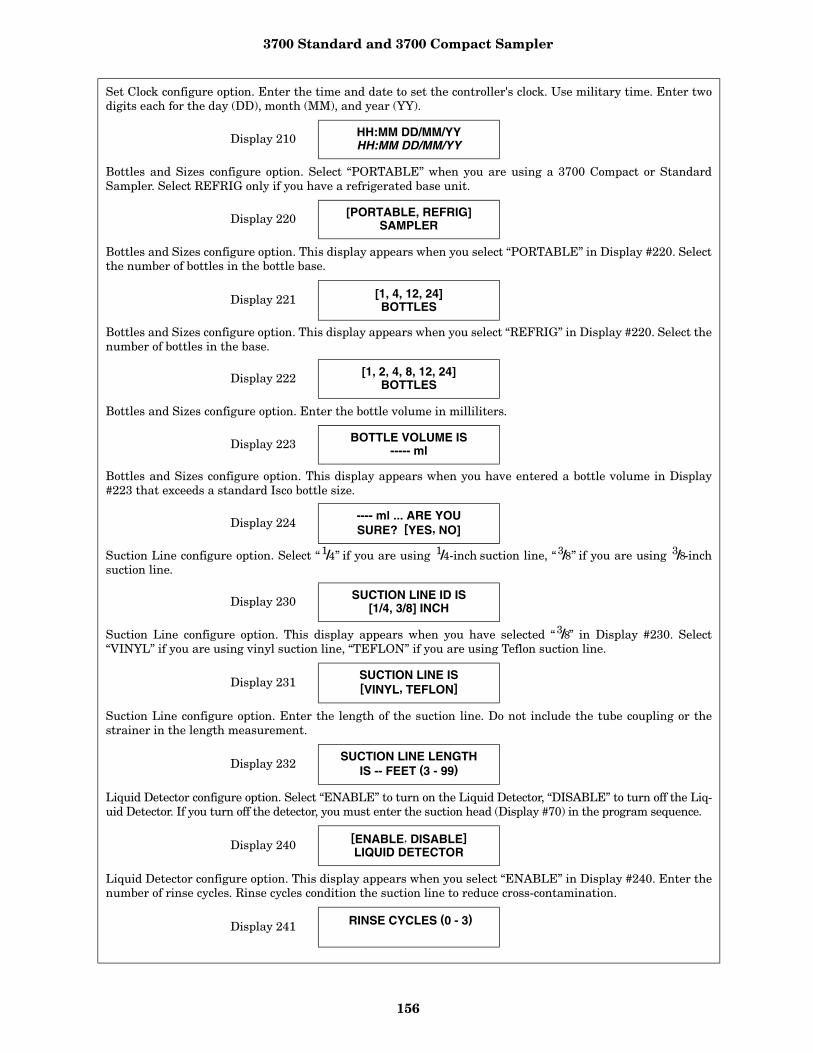
3700 Standard and 3700 Compact Sampler
156
Set Clock configure option. Enter the time and date to set the controller's clock. Use military time. Enter twodigits each for the day (DD), month (MM), and year (YY).
Display 210 HH:MM DD/MM/YYHH:MM DD/MM/YY
Bottles and Sizes configure option. Select “PORTABLE” when you are using a 3700 Compact or StandardSampler. Select REFRIG only if you have a refrigerated base unit.
Display 220 [PORTABLE, REFRIG]SAMPLER
Bottles and Sizes configure option. This display appears when you select “PORTABLE” in Display #220. Selectthe number of bottles in the bottle base.
Display 221 [1, 4, 12, 24] BOTTLES
Bottles and Sizes configure option. This display appears when you select “REFRIG” in Display #220. Select thenumber of bottles in the base.
Display 222 [1, 2, 4, 8, 12, 24] BOTTLES
Bottles and Sizes configure option. Enter the bottle volume in milliliters.
Display 223 BOTTLE VOLUME IS----- ml
Bottles and Sizes configure option. This display appears when you have entered a bottle volume in Display#223 that exceeds a standard Isco bottle size.
Display 224 ---- ml ... ARE YOUSURE? [YES, NO]
Suction Line configure option. Select “ 1/4” if you are using 1/4-inch suction line, “3/8” if you are using 3/8-inchsuction line.
Display 230 SUCTION LINE ID IS[1/4, 3/8] INCH
Suction Line configure option. This display appears when you have selected “3/8” in Display #230. Select“VINYL” if you are using vinyl suction line, “TEFLON” if you are using Teflon suction line.
Display 231SUCTION LINE IS[VINYL, TEFLON]
Suction Line configure option. Enter the length of the suction line. Do not include the tube coupling or thestrainer in the length measurement.
Display 232SUCTION LINE LENGTH
IS -- FEET (3 - 99)
Liquid Detector configure option. Select “ENABLE” to turn on the Liquid Detector, “DISABLE” to turn off the Liq-uid Detector. If you turn off the detector, you must enter the suction head (Display #70) in the program sequence.
Display 240[ENABLE, DISABLE]LIQUID DETECTOR
Liquid Detector configure option. This display appears when you select “ENABLE” in Display #240. Enter thenumber of rinse cycles. Rinse cycles condition the suction line to reduce cross-contamination.
Display 241 RINSE CYCLES (0 - 3)
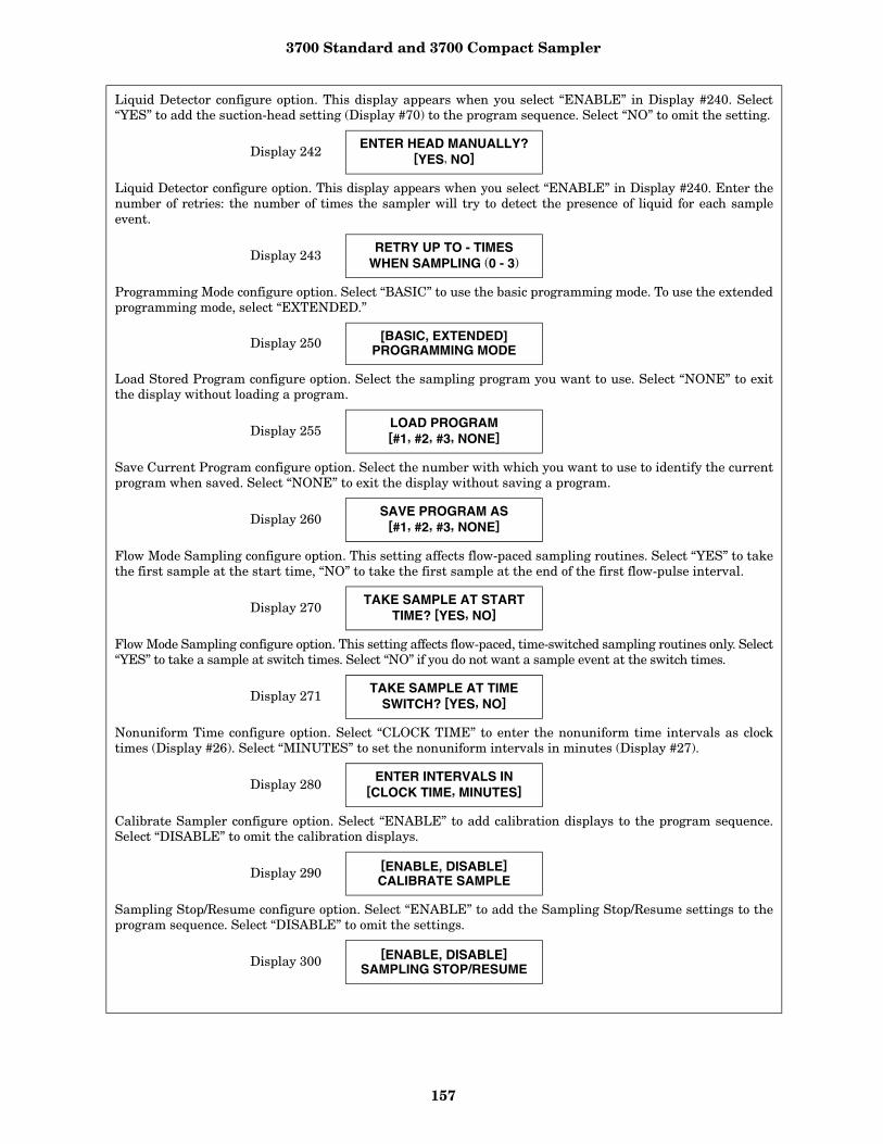
3700 Standard and 3700 Compact Sampler
157
Liquid Detector configure option. This display appears when you select “ENABLE” in Display #240. Select“YES” to add the suction-head setting (Display #70) to the program sequence. Select “NO” to omit the setting.
Display 242ENTER HEAD MANUALLY?
[YES, NO]
Liquid Detector configure option. This display appears when you select “ENABLE” in Display #240. Enter thenumber of retries: the number of times the sampler will try to detect the presence of liquid for each sampleevent.
Display 243RETRY UP TO - TIMES
WHEN SAMPLING (0 - 3)
Programming Mode configure option. Select “BASIC” to use the basic programming mode. To use the extendedprogramming mode, select “EXTENDED.”
Display 250 [BASIC, EXTENDED]PROGRAMMING MODE
Load Stored Program configure option. Select the sampling program you want to use. Select “NONE” to exitthe display without loading a program.
Display 255LOAD PROGRAM[#1, #2, #3, NONE]
Save Current Program configure option. Select the number with which you want to use to identify the currentprogram when saved. Select “NONE” to exit the display without saving a program.
Display 260SAVE PROGRAM AS
[#1, #2, #3, NONE]
Flow Mode Sampling configure option. This setting affects flow-paced sampling routines. Select “YES” to takethe first sample at the start time, “NO” to take the first sample at the end of the first flow-pulse interval.
Display 270TAKE SAMPLE AT START
TIME? [YES, NO]
Flow Mode Sampling configure option. This setting affects flow-paced, time-switched sampling routines only. Select“YES” to take a sample at switch times. Select “NO” if you do not want a sample event at the switch times.
Display 271TAKE SAMPLE AT TIME
SWITCH? [YES, NO]
Nonuniform Time configure option. Select “CLOCK TIME” to enter the nonuniform time intervals as clocktimes (Display #26). Select “MINUTES” to set the nonuniform intervals in minutes (Display #27).
Display 280ENTER INTERVALS IN
[CLOCK TIME, MINUTES]
Calibrate Sampler configure option. Select “ENABLE” to add calibration displays to the program sequence.Select “DISABLE” to omit the calibration displays.
Display 290[ENABLE, DISABLE]CALIBRATE SAMPLE
Sampling Stop/Resume configure option. Select “ENABLE” to add the Sampling Stop/Resume settings to theprogram sequence. Select “DISABLE” to omit the settings.
Display 300[ENABLE, DISABLE]
SAMPLING STOP/RESUME

3700 Standard and 3700 Compact Sampler
158
Sampling Stop/Resume configure option. This display appears when you select “ENABLE” in Display #300.Select “YES” to take a sample at stop times. Select “NO” if you do not want a sample event at the stop times.
Display 301SAMPLE AT STOP?
[YES, NO]
Sampling Stop/Resume configure option. This display appears when you select “ENABLE” in Display #300.Select “YES” to take a sample at the resume times. Select “NO” if you do not want a sample event at theresume times.
Display 302SAMPLE AT RESUME?
[YES, NO]
Start Time Delay configure option. Enter the amount of time, in minutes, you want to delay the start time.This entry affects programs that do not have a programmed start time.
Display 310---- MINUTE DELAY
TO START (0 - 9999)
Enable Pin configure option. Select “YES” to take a sample at the time the sampler becomes disabled. Select“NO” if you do not want a sample event when the sampler becomes disabled.
Display 321SAMPLE UPON DISABLE?
[YES, NO]
Enable Pin configure option. Select “YES” to take a sample when the sampler becomes enabled; i.e., ceases toreceive an inhibit signal from a flow meter or a Liquid Level Actuator. Note: No sample will be taken if theenable signal is used to initiate the start-time delay countdown. Select “NO” if you do not want a sample eventwhen the sampler becomes enabled.
Display 322 SAMPLE UPON ENABLE?[YES, NO]
Enable Pin configure option. Select “YES” to restart the sample interval countdown at the time the sampler isenabled. The interval countdown is determined by the setting if “NO” is selected in Display #324.
Display 323 SAMPLE UPON ENABLE?[YES, NO]
Enable Pin configure option. This display appears if you select “NO” in Display #323. Select “YES” to freezethe sample interval when the sampler becomes disabled. When the sampler is enabled, the interval count-down continues from the point where it had stopped. Select “NO” to let the sample interval countdown con-tinue while the sampler is disabled.
Display 324INHIBIT COUNTDOWN?
[YES, NO]
Event Mark configure option. Select “CONTINUOUS SIGNAL” to send a variable-duration event mark signalfrom pin E of the flow meter connector. Select “PULSE” to send a 3-second event mark signal.
Display 330[CONTINUOUS SIGNAL,
PULSE]
Event Mark configure option. This setting appears when you select “CONTINUOUS SIGNAL” in Display#330. Select “PUMP CYCLE” to transmit the event mark signal during the entire pump cycle, including anyprogrammed rinses and retries. Select “FWD PUMPING ONLY” to send the signal when the pump is deliver-ing a sample volume only.
Display 331 DURING [PUMP CYCLE,FWD PUMPING ONLY]

3700 Standard and 3700 Compact Sampler
159
Event Mark configure option. This setting appears when you select “PULSE” in Display #330. Select “PURGE”to transmit an event mark signal to a flow meter at the beginning of the pre-sample purge. Select “FWDPUMPING” to transmit a signal when the pump switches forward to deliver the sample volume.
Display 332 AT THE BEGINNING OF[PURGE, FWD PUMPING]
Purge Counts configure option. Enter the number of pre-sample pump counts needed to purge the suction line.This value is set to 150 when the controller is reinitialized.
Display 340--- PRE-SAMPLE
COUNTS (0 - 9999)
Purge Counts configure option. Enter the number of post-sample pump counts needed to purge the suctionline. The Controller derives the number that initially appears in this display from the suction line ID andlength entered in Display #230 and #232.
Display 341--- POST-SAMPLECOUNTS (0 - 9999)
Tubing Life configure option. This informational display communicates the pump counts elapsed since the lastreset and the counts required to trigger the Pump Tubing Warning. Exit this display by pressing any key.
Display 350 ------ PUMP COUNTS,WARNING AT ------
Tubing Life configure option. After changing the pump tube, select “YES” to reset the pump counter to zero.Select “NO” to leave the counter unchanged.
Display 351 --- POST-SAMPLECOUNTS (0 - 9999)
Tubing Life configure option. Enter the number of pump counts required to trigger the pump-count warning ifthe factory setting is not suitable. This value is set to 500,000 when the controller is reinitialized.
Display 352 ------ PUMP COUNTSTO WARNING
Program Lock configure option. Select “ENABLE” to turn on the program lock. If you enable the program lock,input displays are protected by a pass-number: 3700. The controller will not allow you to make any changes toa program or configure sequence setting until you enter the pass-number when requested. Select “DISABLE”to turn the program lock off.
Display 360 [ENABLE, DISABLE]PROGRAM LOCK
Sampler ID configure option. Enter the sampler identification here. The sampler will accept as many as 10 charac-ters, including periods (press resume sampling), dashes (press manual sample), and spaces (press start sampling).
Display 365 SAMPLER ID NUMBER IS----------
Run Diagnostics configure option. Select “YES” to run the distributor test. Select “NO” to skip the test. Testthe distributor by moving it to Position 24 then back to Position 1.
Display 370TEST DISTRIBUTOR?
[YES, NO]
Run Diagnostics configure option. Select “YES” to “reinitialize” (reset) the controller: the entire RAM – with theexception of the configure option settings for current pump-count total, number of bottles, bottle size, suction-linelength, and sampler ID – will be reset to factory settings. Select “NO” the leave the settings unchanged.
Display 371 RE-INITIALIZE?[YES, NO]

3700 Standard and 3700 Compact Sampler
160
Appendix D Calculating Flow Increment Between Samples
The 3700 Sampler will accept flow-proportionalinputs from an external flow meter or flow logger.These electronic flow-input signals are transmittedto the sampler at fixed increments of total flow, forexample, every 10,000 gallons. Each time 10,000gallons of liquid flows past the flow meter, it sendsa signal to the sampler, which registers it as a sin-gle flow pulse. You can program the sampler tototalize any number of flow pulses from 1 to 9,999before initiating a sampling event. For example, ifthe sampler were programmed to totalize 5 flowpulses and each flow pulse represented 10,000 gal-lons of total flow, a sample would be collected eachtime 50,000 gallons (5 flow pulses of 10,000 gallonseach) had passed the flow meter.
Time Interval Known - If the desired averagetime interval between individual samples isknown, the flow increment between samples can bedetermined by calculating how much flow (basedon the average flow rate) occurs during that timeinterval. For example, assume that the averageflow is 2.5 MGD and it is desired to collect a sam-ple every 30 minutes. The flow increment betweensamples is calculated:
2.5 MGD = 2,500,000 ga/day
2,500,000 gal/day x 1 day/24 hr x 1 hr/60 min = 1736 gal/min
736 gal/min x 30 min/sample = 52,080 gal/sample
Thus, the desired flow increment between samplesis approximately 52,000 gallons.
Number of Samples Known - Alternatively, ifthe total number of samples to be collected over thetotal sampling period is known, the flow incrementbetween samples can be determined by calculatinghow much total flow will occur during the sam-pling period, and dividing this by the total numberof samples to be collected. For example, assumethat the average flow is 1.75 MGD, that the com-posite sampling period is 2 days, and that it isdesired to collect 100 individual samples. The flowincrement between samples is calculated:
1.75 MGD = 1,750,000 gal/day
1,750,000 gal/day x 2 days = 3,500,000 gal
3,500,000 gal ÷ 100 samples = 35,000 gal/sample
Thus, the desired flow increment between samplesis approximately 35,000 gallons.
Calculation of Number of Flow Pulses - Oncethe desired flow increment between samples isknown, the number of flow pulses to be pro-grammed into the sampler may be calculated,assuming that the volume of the flow pulses fromthe flow meter is known. The number of flowpulses is calculated by dividing the flow incrementbetween samples by the volume of each flow pulse.Using the first example above, the flow incrementbetween samples was calculated as 52,000 gallons;assume that each flow pulse represents 10,000 gal-lons of flow. The number of flow pulses to be pro-grammed into the sampler is calculated:
52,000 gal ÷ 10,000 gal/flow pulse = 5.2 flow pulses
Rounding this to an even number results in 5 flowpulses to be programmed into the sampler. This inturn results in a flow increment between samplesof 50,000 gallons (5 flow pulses × 10,000 gallons/flow pulse).
Total Number Of Samples - To calculate the totalnumber of samples to be collected, three quantitiesmust be known: the average flow rate, the flowincrement between samples (calculated above), andthe total time over which the composite sample is tobe collected. The total number of samples to be col-lected is determined by first calculating the totalflow volume over the sampling period, and thendividing this by the flow increment between sam-ples. For example, assume that the average flow is2.5 MGD, the flow increment between samples is50,000 gallons, and the composite sample is to becollected over a 24 hour period. The total flow vol-ume over a 24 hour period is:
2.5 MGD = 2,500,000 gal/day
2,500,000 gal/day x 1 day = 2,500,000 gal
The total number of samples to be collected in this24 hour period is then calculated:
2,500,000 gal ÷ 50,000 gal/samples = 50 samples
Thus, based on an average flow of 2.5 MGD, 50samples will be collected.
3700 Standard and 3700 Compact Sampler
161
Calculation of Sample Volume - To calculatethe volume of each individual sample, the volumeof the composite sample container being used andthe total number of samples to be collected (calcu-lated above) must be known. The individual sam-ple volume is calculated by simply dividing thevolume of the composite sample container beingused by the total number of samples to be col-lected. For example, assume that a 2.5 gallon(9,400 ml) plastic container is being used, and thata total of 50 samples are to be collected in it. Theindividual sample volume is then calculated:
9400 ml ÷ 50 samples = 188 ml
Sample Volume Considerations - Thus, a sam-ple volume of 188 ml will result in the desiredcomposite sample. Because of the basic uncer-tainty of the delivered sample volume exactlymatching the programmed nominal sample volumeand the 10 ml sample repeatability, it is good prac-tice to select a nominal sample volume which isslightly smaller than the calculated sample vol-ume. This is to prevent overfilling of the samplecontainer. In the example, an individual nominalsample volume of 125 ml might be a prudentchoice. For critical applications, calibration of thesample volume can be used. It is important toselect an individual sample volume which will notresult in an overfilled sample container underworst-case conditions.
The nominal volume of the composite sample maybe calculated by multiplying the programmed nom-inal sample volume by the total number of samplesto be collected. In the example:
125 ml/sample x 50 samples = 6,250 ml
This calculated total volume may vary from theactual total volume because of variations in theactual volume of each individual sample. The totaltime needed to collect the 50 individual samplesmay vary from the desired 24 hour period becauseof variations in the average flow rate from the 2.5MGD figure used in these calculations.

3700 Standard and 3700 Compact Sampler
162
Appendix E GlossaryBottles per sample - Bottles per sample is thenumber of bottles receiving sample volumes ateach sample event.
Composite sampling - In composite sampling,multiple sample volumes are placed in bottle sets.Typically, composite sampling uses a single con-tainer. A composite sample represents an averageof the characteristics of the flow stream for theelapsed time of sampling.
Controller - The controller is a collection of elec-tronic components, which govern the actions of thesampler. It includes the microprocessor, RAM(Random Access Memory), ROM (Read Only Mem-ory) and its imbedded software, the LCD (LiquidCrystal Display), and the keypad.
Cross contamination - Cross contaminationoccurs when portions of previous samples aremixed with the current sample. For example, crosscontamination results when residual amounts ofsample remain in the suction line or pump tubefrom a previous sample event.
Event mark - An event mark is a signal that thesampler sends to a flow meter or other device aeach sample event. Each time the flow meterreceives an event mark pulse, the flow meterplaces a mark on the its recording chart. Markingthe recording chart cross-references the chartedflow with the sample events.
Multiplexing - There are two types of multiplex-ing: samples per bottle and bottles per sample. Insamples per bottle multiplexing, a bottle receivessamples from more than one sample event. In bot-tles per sample multiplexing, equal sample vol-umes are placed in more than one bottle at eachsample event.
Post-purge - See post-sample purge.
Pre-purge - See pre-sample purge.
Post-sample purge - Post-sample purge refers tothe suction line purge that follows the delivery ofthe sample volume(s). It is also called post-purge.î
Pre-sample purge - Pre-sample purge refers tothe suction line purge that precedes the delivery ofthe sample volume(s). It is also called pre- purge.
Real-time clock - A real-time clock can be set tothe actual time and date.
Sample event - A sample event consists of thecomplete sampling cycle resulting in the collectionand distribution of one or more equal sample vol-umes. A sample event includes pre-sample andpost-sample purges, line rinses, liquid detectionretries, and deliveries of sample volumes. No morethan one sample volume is placed in any one bottleduring a sample event.
Sample volume - The sample volume is the dis-crete, programmed amount of sample delivered toeach bottle. A single sample event may deliver sev-eral sample volumes.
Samples per bottle - Samples per bottle is thenumber of discrete sample volumes placed in eachbottle.
Sampling program - See sampling routine.
Sampling routine - A sampling routine, alsocalled a sampling program, is the process of takingsamples according to the program settings youenter when programming and configuring the con-troller. The program settings define the samplepacing, distribution, volume, and key clock times.
Selection - A selection is represented by a blink-ing word or number in an input display. The blink-ing selection indicates the current choice or value.Selections are accepted and stored by pressing theenter/program key.
Suction head - Suction head is the vertical dis-tance from the surface of the flow stream to thepump inlet.
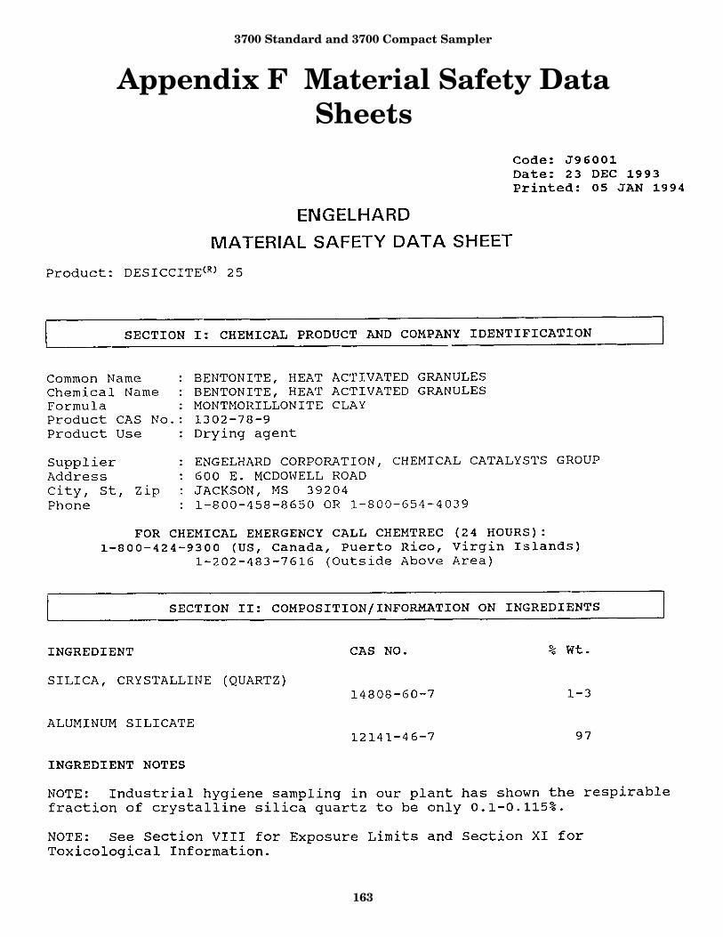
3700 Standard and 3700 Compact Sampler
163
Appendix F Material Safety Data Sheets
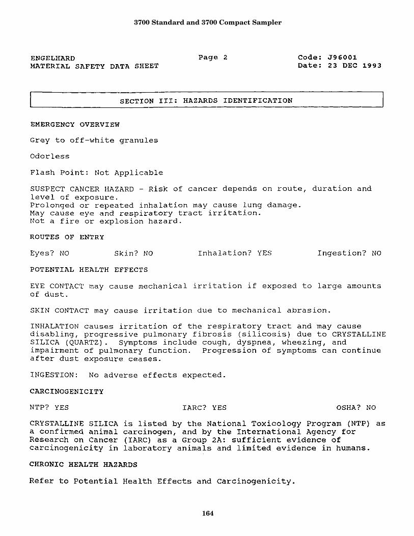
3700 Standard and 3700 Compact Sampler
164

3700 Standard and 3700 Compact Sampler
165
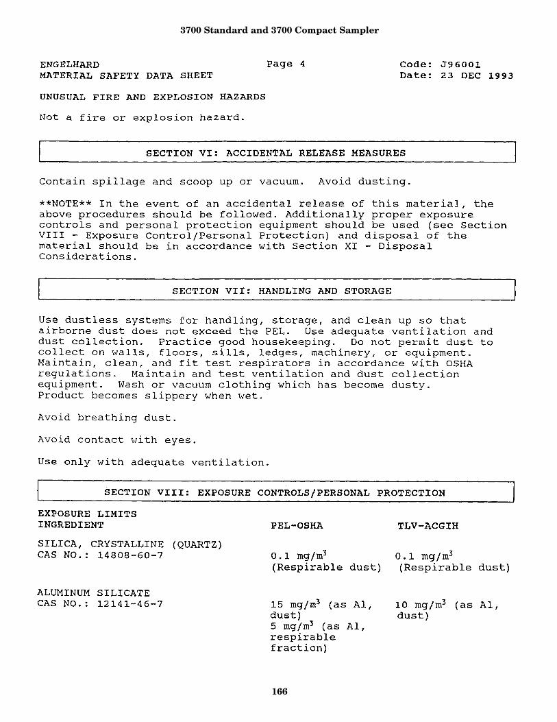
3700 Standard and 3700 Compact Sampler
166
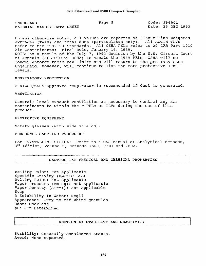
3700 Standard and 3700 Compact Sampler
167
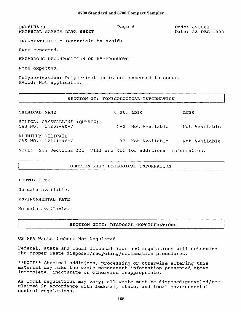
3700 Standard and 3700 Compact Sampler
168
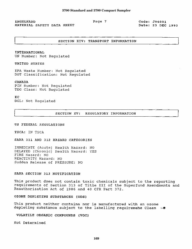
3700 Standard and 3700 Compact Sampler
169
3700 Standard and 3700 Compact Sampler
170
3700 Standard and 3700 Compact Sampler
171

3700 Standard and 3700 Compact Sampler
172
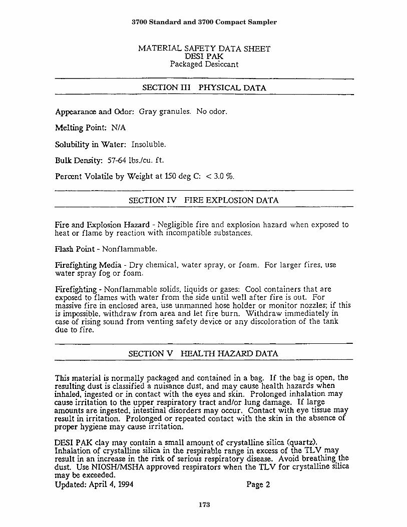
3700 Standard and 3700 Compact Sampler
173
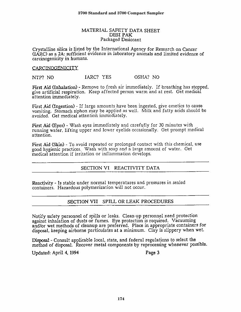
3700 Standard and 3700 Compact Sampler
174
3700 Standard and 3700 Compact Sampler
175

3700 Standard and 3700 Compact Sampler
176

3700 Standard and 3700 Compact Sampler
177

3700 Standard and 3700 Compact Sampler
178
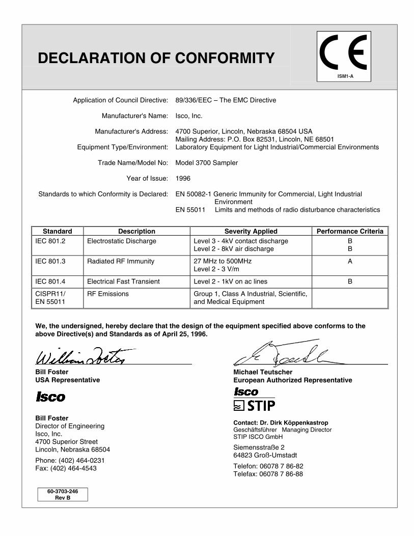
Compliance Statements
DECLARATION OF CONFORMITY
Application of Council Directive: 89/336/EEC – The EMC Directive
Manufacturer's Name: Isco, Inc.
Manufacturer's Address: 4700 Superior, Lincoln, Nebraska 68504 USAMailing Address: P.O. Box 82531, Lincoln, NE 68501
Equipment Type/Environment: Laboratory Equipment for Light Industrial/Commercial Environments
Trade Name/Model No: Model 3700 Sampler
Year of Issue: 1996
Standards to which Conformity is Declared: EN 50082-1 Generic Immunity for Commercial, Light IndustrialEnvironment
EN 55011 Limits and methods of radio disturbance characteristics
Standard Description Severity Applied Performance CriteriaIEC 801.2 Electrostatic Discharge Level 3 - 4kV contact discharge
Level 2 - 8kV air dischargeBB
IEC 801.3 Radiated RF Immunity 27 MHz to 500MHzLevel 2 - 3 V/m
A
IEC 801.4 Electrical Fast Transient Level 2 - 1kV on ac lines B
CISPR11/EN 55011
RF Emissions Group 1, Class A Industrial, Scientific,and Medical Equipment
We, the undersigned, hereby declare that the design of the equipment specified above conforms to theabove Directive(s) and Standards as of April 25, 1996.
Bill FosterUSA Representative
Bill FosterDirector of EngineeringIsco, Inc.4700 Superior StreetLincoln, Nebraska 68504
Phone: (402) 464-0231Fax: (402) 464-4543
60-3703-246Rev B
Michael TeutscherEuropean Authorized Representative
Contact: Dr. Dirk KöppenkastropGeschäftsführer Managing DirectorSTIP ISCO GmbH
Siemensstraße 264823 Groß-Umstadt
Telefon: 06078 7 86-82Telefax: 06078 7 86-88

Warranty
Before returning any instrument for repair, please call, fax, or e-mail the Isco servicedepartment for instructions. Many problems can often be diagnosed and corrected overthe phone, or by e-mail, without returning the instrument to the factory.
Instruments needing factory repair should be packed carefully, preferably in theoriginal carton, and shipped to the attention of the service department. Small, non-fragile items can be sent by insured parcel post. PLEASE BE SURE TO ENCLOSE ANOTE EXPLAINING THE DEFECT.
Return instruments to: Isco, Inc. - Attention Repair Service4700 Superior StreetLincoln NE 68504 USA
Mailing address: Isco, Inc.PO Box 82531Lincoln NE 68501 USA
Phone: Repair service: (800)775-2965 (lab instruments)
(800)228-4373 (samplers & flowmeters)
Sales & General Information (800)228-4373 (USA & Canada)
Fax: (402) 465-3001
Email: [email protected]
One Year Limited Warranty *Factory Service
Isco instruments covered by this warranty
have a one-year limited warranty covering
parts and labor.
Any instrument that fails during the warranty
period, due to faulty parts or workmanship,
will be repaired at the factory at no charge to
the customer. Isco's exclusive liability is
limited to repair or replacement of defective
instruments. Isco is not liable for
consequential damages.
Isco will pay surface transportation charges
both ways within the 48 contiguous United
States if the instrument proves to be defective
within 30 days of shipment. Throughout the
remainder of the warranty period, the
customer will pay to return the instrument to
Isco, and Isco will pay surface transportation
to return the repaired instrument to the
customer. Isco will not pay air freight or
customer's packing and crating charges.
The warranty for any instrument is the one in
effect on date of shipment. Warranty period
begins on the shipping date, unless Isco
agrees in writing to a different date.
Excluded from this warranty are normal
wear; expendable items such as charts,
ribbon, tubing, and glassware; and damage
due to corrosion, misuse, accident, or lack of
proper maintenance. This warranty does not
cover Isco on-line Process Analyzers and
certain Isco SFE instruments, which are
covered under different warranty terms, nor
does it cover products not sold under the Isco
trademark or for which any other warranty is
specifically stated in sales literature.
This warranty is expressly in lieu of all other
warranties and obligations and Isco
specifically disclaims any warranty of
merchantability or fitness for a particular
purpose. Any changes in this warranty must
be in writing and signed by a corporate
officer.
The warrantor is Isco, Inc. 4700 Superior,
Lincoln, NE 68504, U.S.A.
November 2000 • #2217
* This warranty applies to USA customers. Customers in other countries should contact their Isco dealer for warranty service.


