WINLAB Guest LectureS. Paul 03/03/2006
IP Multicast: Protocols, Deployment, and
ManagementSanjoy Paul
Outline
• Part-I: Multicasting Fundamentals
• Part-II: IP Multicast
• Part-III: Reliable Multicast Transport Protocols
• Part-IV: Multicast Congestion Control

» Part-I: Multicasting Fundamentals
• PartPart--II: IP MulticastII: IP Multicast
•• PartPart--III: Reliable Multicast Transport ProtocolsIII: Reliable Multicast Transport Protocols
•• PartPart--IV: Multicast Congestion ControlIV: Multicast Congestion Control
What is Multicast ?
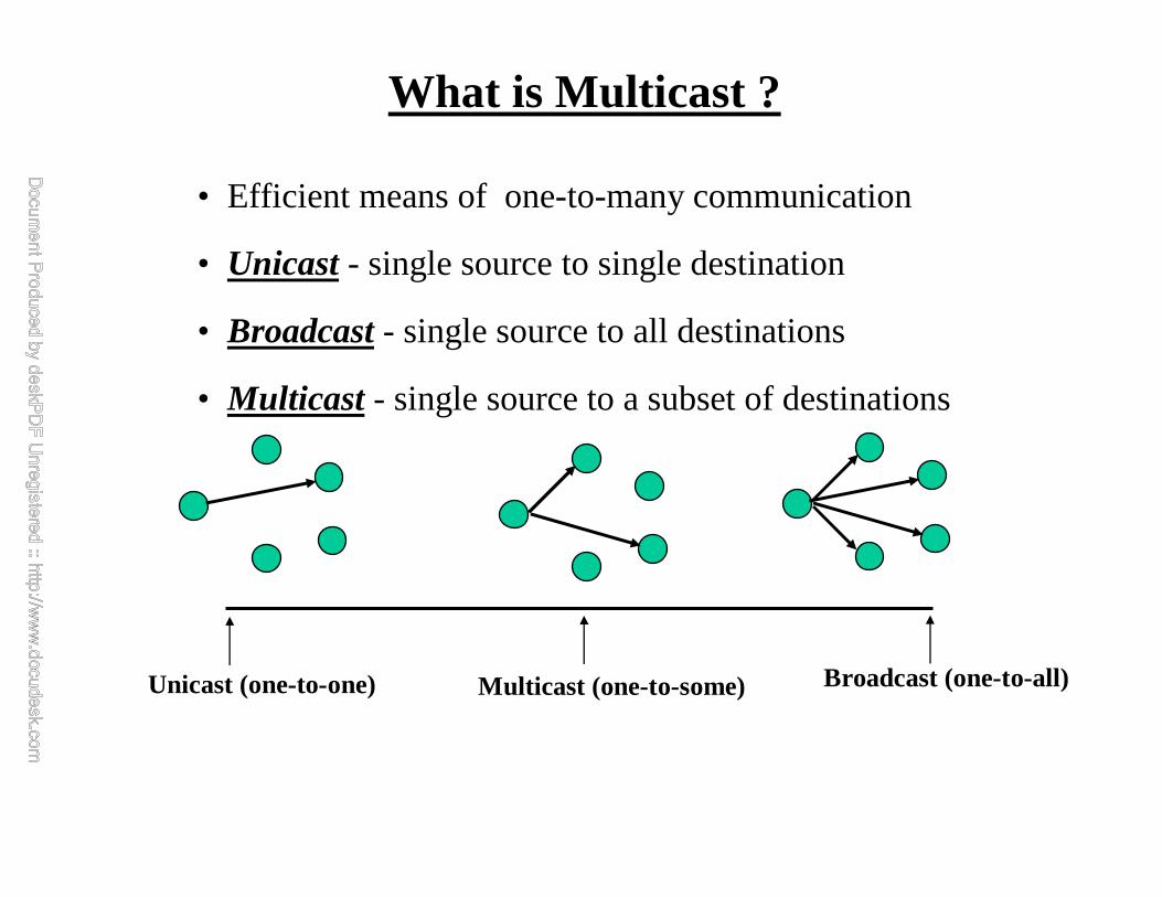
• Efficient means of one-to-many communication
• Unicast- single source to single destination
• Broadcast- single source to all destinations
• Multicast - single source to a subset of destinations
Unicast (one-to-one) Multicast (one-to-some) Broadcast (one-to-all)

Reliability100%
200 ms 2 s 20 s
InteractiveConferencing
Multimediadistribution Document distribution
Multicasting Applications
•Audio/video messages •Distance learning•Multimedia entertainment
•Website concurrency•Document distribution•Software distribution•Financial news •Database concurrency•Employee communications•Communications with branches, •dealerships, retail outlets, suppliers
•Video and audio conferencing
•Interactive simulation
End-to-end Latency--->

WINLAB Guest LectureS. Paul 03/03/2006
Current Internet Protocol (TCP/IP) Is Inefficient For One-to-many Applications
Sender
Router
File A
File A (Duplicate)
One-to-many distribution Using TCP/IP
Receiver 2Receiver 1

One-to-many distribution Using TCP/IP Sender
Router
RouterReceiver 1
Router
Internet/IntranetRouter
Receiver 2 Receiver 3Receiver 4
Receiver5
• The Result– multiple copies of every packet– multiple buffers– multiple connections

Efficient Multicasting
Sender
Router
RouterReceiver 1
Router
Internet/IntranetRouter
Receiver 2Receiver 3
Receiver 4
Receiver5
• The Result– single copy of every packet– single buffer– single multicast connection
WINLAB Guest LectureS. Paul 03/03/2006
• Efficient bandwidth utilization -- good for Internet Service Providers (ISPs)
• Avoids server overload -- good for content providers
• Prevents network congestion -- good for ISPs
• Get information to more users simultaneously -- good for Dow Jones etc.
• Reach thousands or millions of people at once – IPTV, good for advertising (think super bowl)
• Use Internet for “push” as opposed to “pull” -- good for sending “alerts”
• Use for replicated websites/databases -- good for content providers
Why Multicast ?

Best-Effort vs. Reliable Multicast
• Not all applications require reliability– live audio/video distribution
– real-time conferencing
• Best-effort multicast applications use UDP/IP-Multicast
• Reliable multicast applications can use RMTP/UDP/IP-Multicast
IP IP Multicast
TCP UDP
Unicast Appl Multicast Appl
UDP
RMTP
WINLAB Guest LectureS. Paul 03/03/2006
• PartPart--I: Multicasting FundamentalsI: Multicasting Fundamentals
» Part-II: IP Multicast
• PartPart--III: Reliable Multicast Transport ProtocolsIII: Reliable Multicast Transport Protocols
•• PartPart--IV: Multicast Congestion ControlIV: Multicast Congestion Control
WINLAB Guest LectureS. Paul 03/03/2006
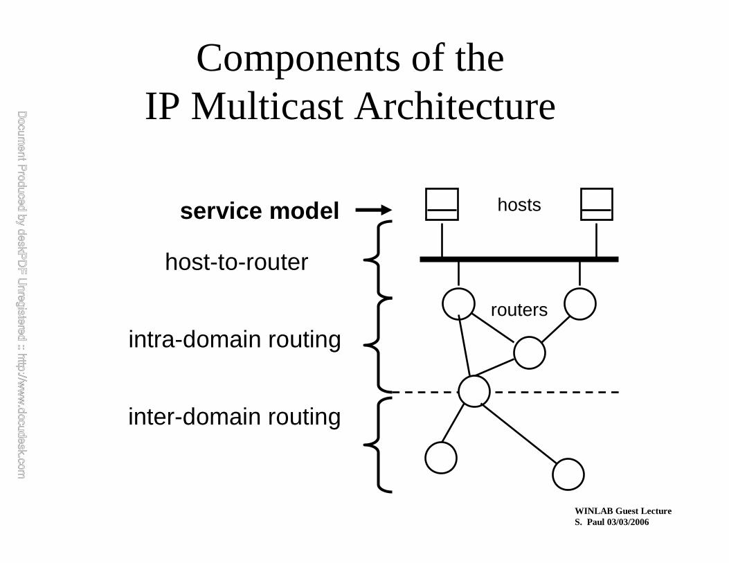
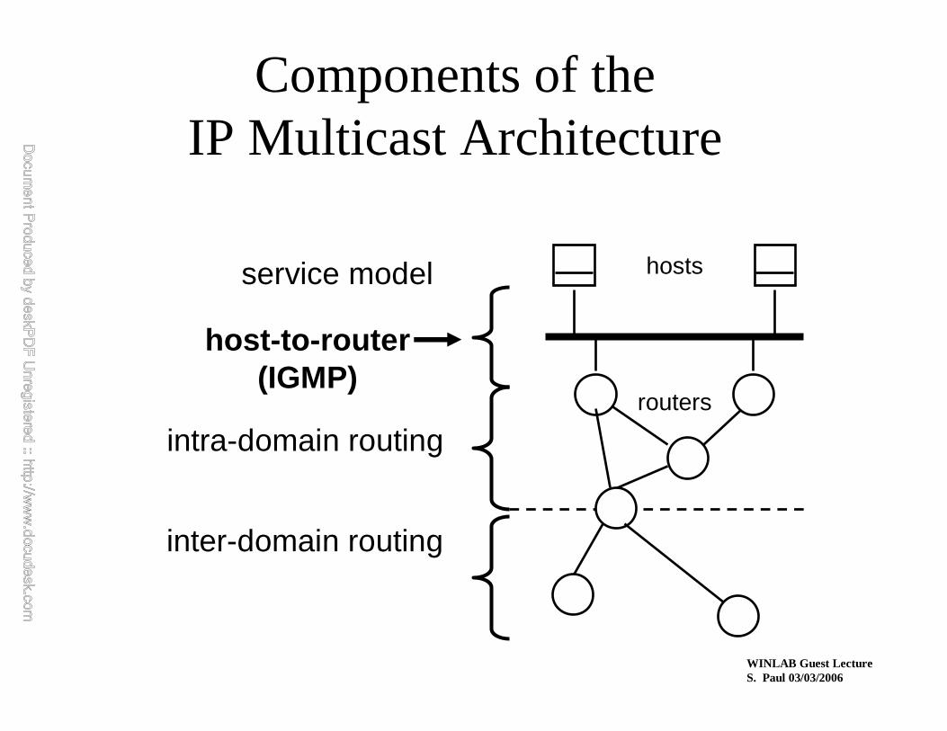
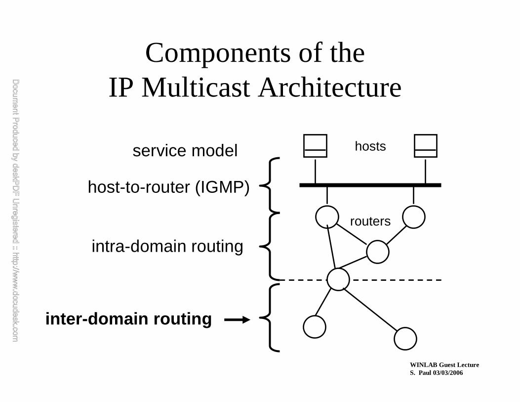
Components of theIP Multicast Architecture
hosts
routers
service model
host-to-router
intra-domain routing
inter-domain routing
WINLAB Guest LectureS. Paul 03/03/2006
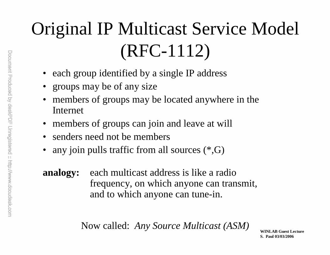
Original IP Multicast Service Model(RFC-1112)
• each group identified by a single IP address• groups may be of any size• members of groups may be located anywhere in the
Internet• members of groups can join and leave at will• senders need not be members• any join pulls traffic from all sources (*,G)
analogy: each multicast address is like a radiofrequency, on which anyone can transmit,and to which anyone can tune-in.
Now called: Any Source Multicast (ASM)

•Class D Group addressing
— IP address range: 224.0.0.0 --- 239.255.255.255
IP Multicast -- Group Addressing
INTERNET/INTRANET
SENDERS
RECEIVERS subscribed to Group Address 224.9.9.9
Sender’s IP 224.9.9.9 Multicast Data
Destination Address
IP Header
Sender
Receiver
S
S
S
1110….

• IP multicast (H1 multicasting to H2 and H4) can be achieved at the link layer using:
— link-layer broadcast
IP Multicast using Ethernet Broadcast/Multicast
IP Module
EthernetDriver
IP Module
EthernetDriver
IP Module
EthernetDriver
IP Module
EthernetDriver
IP Module
EthernetDriver
H1 H2 H3 H4 H5
Src addr Dst addr
IP Module
EthernetDriver
IP Module
EthernetDriver
IP Module
EthernetDriver
IP Module
EthernetDriver
IP Module
EthernetDriver
H1 H2 H3 H4 H5
— link-layer multicastH1’s addr Ethernet m/cast addr IP Multicast Datagram
Src addr Dst addr
H1’s addr ff:ff:ff:ff:ff:ff IP Multicast Datagram

Mapping IP Multicast Address to Ethernet Address
00 0 0 0 0 0 0 1 0 0 0 0 0 0 0 0 0 1 0 1 1 1 1 0
1 1 1 0 x x x x x
Most significant 9 bits ofIP Multicast Address haveno effect on the Ethernet Multicast Address
Least Significant 23 bits of IP Multicast Address
Least Significant 23 bits of Ethernet Address
Directly Mapped Into

WINLAB Guest LectureS. Paul 03/03/2006
IP Multicast Service — Sending
• uses normal IP-Send operation, with an IP multicast address specified as the destination
– multicast is UDP based (TCP semantics are too complex)
• must provide sending application a way to:– specify outgoing network interface, if >1 available
– specify IP time-to-live (TTL) on outgoing packet
– enable/disable loopback if the sending host is a member of the destination group on the outgoing interface

WINLAB Guest LectureS. Paul 03/03/2006
IP Multicast Service — Receiving
• two new operations:Join-IP-Multicast-Group ( group-address, interface )
Leave-IP-Multicast-Group ( group-address, interface )
• receive multicast packets for joined groups via normal IP-Receive operation

WINLAB Guest LectureS. Paul 03/03/2006
Source Specific Multicast Model(SSM)
• a “channel” is identified by a (S,G) pair
• groups may be of any size (one sender only)
• members of groups may be located anywhere in the Internet
• members of groups can join and leave at will
• the sender need not be a member
WINLAB Guest LectureS. Paul 03/03/2006
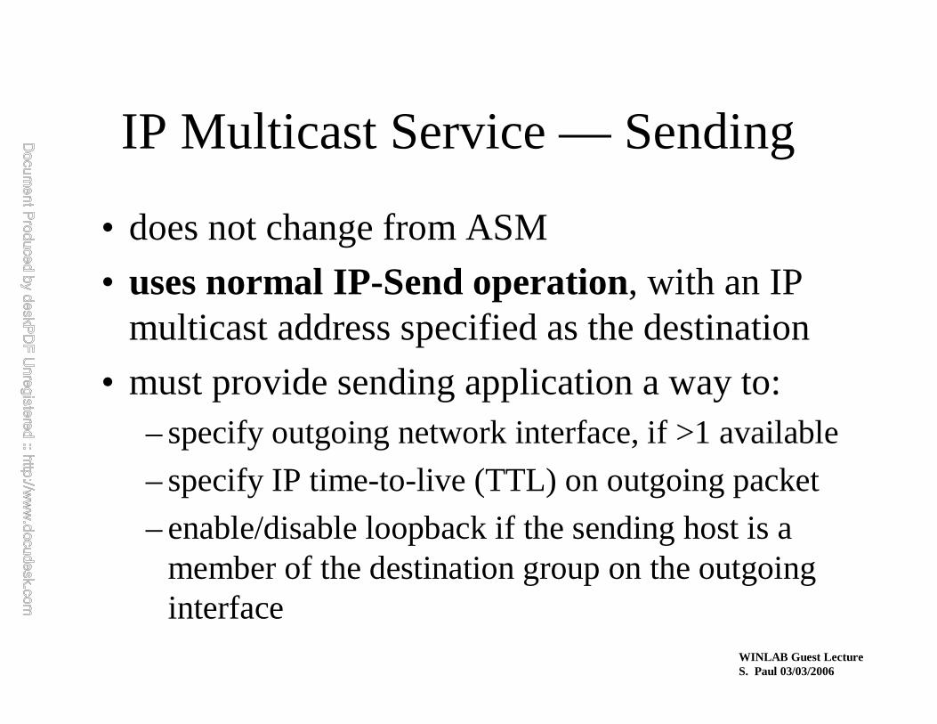
IP Multicast Service — Sending
• does not change from ASM
• uses normal IP-Send operation, with an IP multicast address specified as the destination
• must provide sending application a way to:– specify outgoing network interface, if >1 available
– specify IP time-to-live (TTL) on outgoing packet
– enable/disable loopback if the sending host is a member of the destination group on the outgoing interface

WINLAB Guest LectureS. Paul 03/03/2006
IP Multicast Service — Receiving
• instead of only specifying a group, now must specify a group and a source:
Join-IP-Multicast-Group ( source, group, interface )
Leave-IP-Multicast-Group ( source, group, interface )
• receive multicast packets for joined groups via modified IP-Receive operation

WINLAB Guest LectureS. Paul 03/03/2006
Multicast Service Model
• Set the record straight:
multicast is one-to-many, end-to-end delivery…nothing more
• All of the other services are pseudo-transport (application) layer– reliability, congestion control, security, billing,
audience management, address allocation, etc.
WINLAB Guest LectureS. Paul 03/03/2006
Components of theIP Multicast Architecture
hosts
routers
service model
host-to-router(IGMP)
intra-domain routing
inter-domain routing
WINLAB Guest LectureS. Paul 03/03/2006
Internet Group Management Protocol(IGMP)
• the protocol by which hosts report their multicast group memberships to neighboring routers – RFC-1112 specifies version 1, the original Standard
– RFC-2236 specifies version 2, the most widely used
– IETF draft specifies version 3, imminent deployment
• occupies similar position and role as ICMP in the TCP/IP protocol stack

WINLAB Guest LectureS. Paul 03/03/2006
IGMP Version 1 Message Format
Version 1
Type 1 = Membership Query2 = Membership Report
Checksum standard IP-style checksum ofthe IGMP Message
Group Address group being reported(zero in Queries)
Vers. Type Reserved Checksum
Group Address
WINLAB Guest LectureS. Paul 03/03/2006
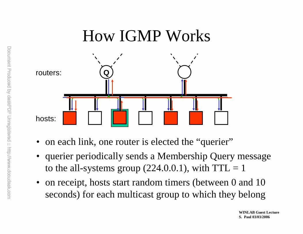
How IGMP Works
• on each link, one router is elected the “querier”
• querier periodically sends a Membership Query messageto the all-systems group (224.0.0.1), with TTL = 1
• on receipt, hosts start random timers (between 0 and 10 seconds) for each multicast group to which they belong
Qrouters:
hosts:

WINLAB Guest LectureS. Paul 03/03/2006
How IGMP Works (cont.)
• when a host’s timer for group G expires, it sends a Membership Report to group G, with TTL = 1
• other members of G hear the report and stop their timers
• routers hear allreports, and time out non-responding groups
Q
G G G G

WINLAB Guest LectureS. Paul 03/03/2006
How IGMP Works (cont.)
• note that, in normal case, only one report message per group present is sent in response to a query
(routers need not know who all the members are,only that members exist)
• query interval is typically 60—90 seconds
• when a host first joins a group, it sends one or two immediate reports, instead of waiting for a query
WINLAB Guest LectureS. Paul 03/03/2006
IGMP Version 2
• changes from version 1:– new message and procedures to reduce “leave
latency”
– standard querier election method specified
– version and type fields merged into a single field
• backward-compatible with version 1
• is currently a Proposed Standard
• the de facto deployed standard
WINLAB Guest LectureS. Paul 03/03/2006
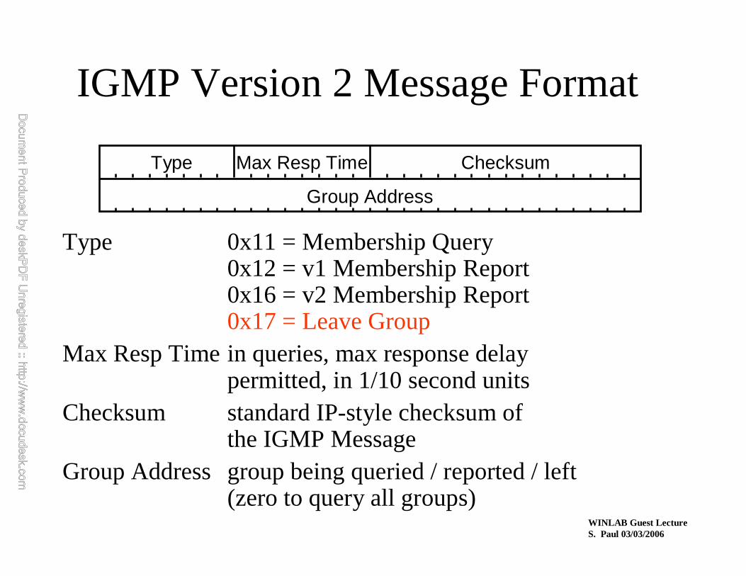
IGMP Version 2 Message Format
Type 0x11 = Membership Query0x12 = v1 Membership Report0x16 = v2 Membership Report0x17 = Leave Group
Max Resp Time in queries, max response delaypermitted, in 1/10 second units
Checksum standard IP-style checksum ofthe IGMP Message
Group Address group being queried / reported / left(zero to query all groups)
Type Max Resp Time Checksum
Group Address
WINLAB Guest LectureS. Paul 03/03/2006
IGMP Version 2:Reducing Leave Latency
• when a host leaves a group, it sends a Leave Group message ifit was the most recent host to report membership in that group
• when querier router hears Leave Group message, it sends a couple of group-specificqueries, specifying a small max-response-time
• if no report heard, routing protocol assumes group is no longer present on the link
WINLAB Guest LectureS. Paul 03/03/2006
IGMP Version 2:Querier Election
• performed by each multicast router on each of its attached interfaces:• initially assume the querier role, and emit
periodic Query messages
• if Query messages heard from a router with a lower address, yield the querier role
• if current querier stops emitting Query messages, reassume the querier role

WINLAB Guest LectureS. Paul 03/03/2006
IGMP Version 3
• currently deployed• changes from version 2:
– extension of service interface and protocol to enablehosts to:
• listen to only a specified setof hosts sending to a group• listen to all but a specified setof hosts sending to a group
– additional protocol to inform a source host when no one is listening, to suppress unnecessary first hop transmission
• backward-compatible with versions 1 & 2

WINLAB Guest LectureS. Paul 03/03/2006
IP Multicast Meets Bridged LANs
• LANs are no longer just rings and “yellow hoses”!
• classic Ethernet bridges forward all multicasts to all segments, in case any receivers are there.
• current/Proposed ways to do better:– IGMP Snooping
– CGMP (Cisco Group Management Protocol)

WINLAB Guest LectureS. Paul 03/03/2006
IGMP Snooping
• bridges look inside received multicast frames for:– IGMP Reports, to learn in which direction(s) group
members reside
– IGMP Queries, DVMRP Probes, MOSPF Hellos, PIM Hellos to learn in which direction(s) multicast routers reside
• multicast data packets forwarded only towards group members and multicast routers.
• IGMP Report suppression done “per branch”rather than “per LAN”

WINLAB Guest LectureS. Paul 03/03/2006
Problems with IGMP snooping
• doesn’t work for non-IP multicasts
• stops working if new multicast routing protocol deployed
• performance cost of snooping inside of every multicast frame

WINLAB Guest LectureS. Paul 03/03/2006
CGMP
• Cisco proprietary approach• designed to eliminate need for bridge to snoop multicast frames• multicast routers send CGMP control messages to bridges,
informing them of group membership
WINLAB Guest LectureS. Paul 03/03/2006
CGMP
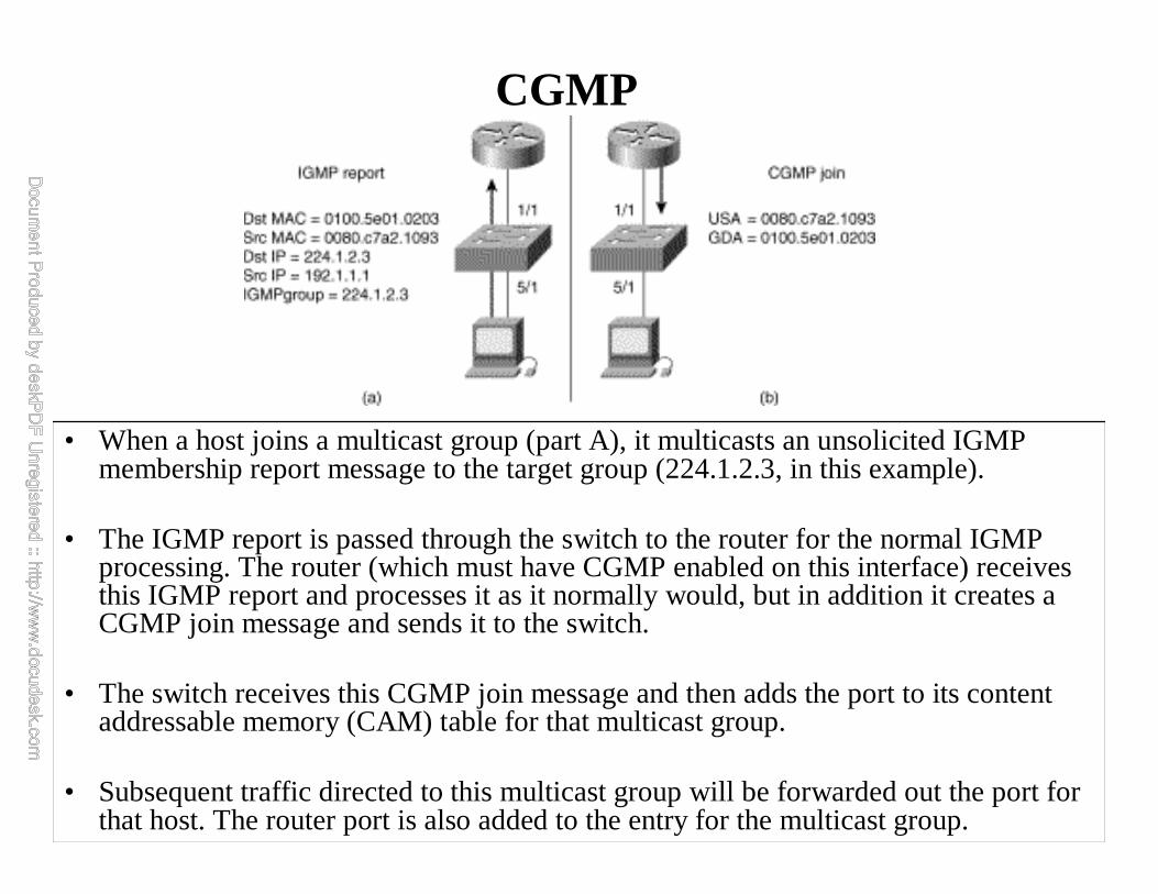
• When a host joins a multicast group (part A), it multicasts an unsolicited IGMP membership report message to the target group (224.1.2.3, in this example).
• The IGMP report is passed through the switch to the router for the normal IGMP processing. The router (which must have CGMP enabled on this interface) receives this IGMP report and processes it as it normally would, but in addition it creates a CGMP join message and sends it to the switch.
• The switch receives this CGMP join message and then adds the port to its content addressable memory (CAM) table for that multicast group.
• Subsequent traffic directed to this multicast group will be forwarded out the port for that host. The router port is also added to the entry for the multicast group.

WINLAB Guest LectureS. Paul 03/03/2006
For More Information on IGMP
• Specifications– IGMPv1: RFC 1112
– IGMPv2: RFC 2236
– IGMPv3: RFC 3376
• WWW page– http://www.ietf.org/html.charters/idmr-
charter.html
• Mailing list– Subscribe to: [email protected]

WINLAB Guest LectureS. Paul 03/03/2006
Components of theIP Multicast Architecture
hosts
routers
service model
host-to-router(IGMP)
intra-domain routing
inter-domain routing

WINLAB Guest LectureS. Paul 03/03/2006
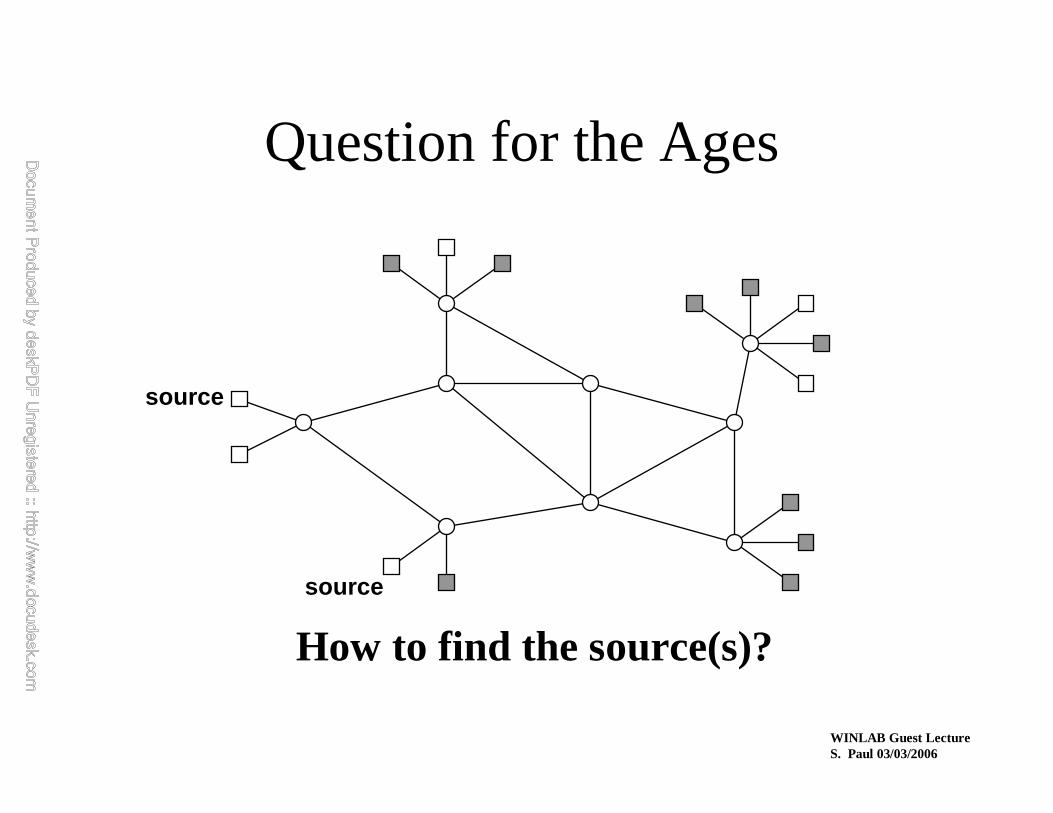
source
Building the Reverse Path
destination

WINLAB Guest LectureS. Paul 03/03/2006
source
Building a Reverse Path Tree
destination
destination
destination

WINLAB Guest LectureS. Paul 03/03/2006
source
Forwarding Data
destination
destination
destination
WINLAB Guest LectureS. Paul 03/03/2006
source
Question for the Ages
How to find the source(s)?
source
WINLAB Guest LectureS. Paul 03/03/2006
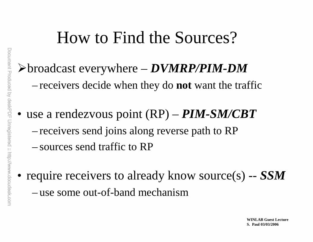
How to Find the Sources?
�broadcast everywhere –DVMRP/PIM-DM– receivers decide when they do not want the traffic
• use a rendezvous point (RP) –PIM-SM/CBT– receivers send joins along reverse path to RP
– sources send traffic to RP
• require receivers to already know source(s) --SSM– use some out-of-band mechanism

WINLAB Guest LectureS. Paul 03/03/2006
The First Intra-Domain Routing Protocol:
DVMRP

WINLAB Guest LectureS. Paul 03/03/2006
Distance-Vector Multicast Routing Protocol
DVMRP consists of two major components:(1) a conventional distance-vector routing protocol (like RIP) which
builds, in each router, a routing table like this:
(2) a protocol for determining how to forward multicast packets,based on the routing table and routing messages of (1)
subnet shortest dist via interface
a 1 i1
b 5 i1
c 3 i2… … …

WIN
LAB
Gue
st L
ectu
reS
. P
aul 0
3/03
/200
6
Exa
mp
le T
op
olo
gyg
g
s
g

WINLAB Guest LectureS. Paul 03/03/2006
Phase 1: Truncated Broadcast
g g
s
g
WINLAB Guest LectureS. Paul 03/03/2006
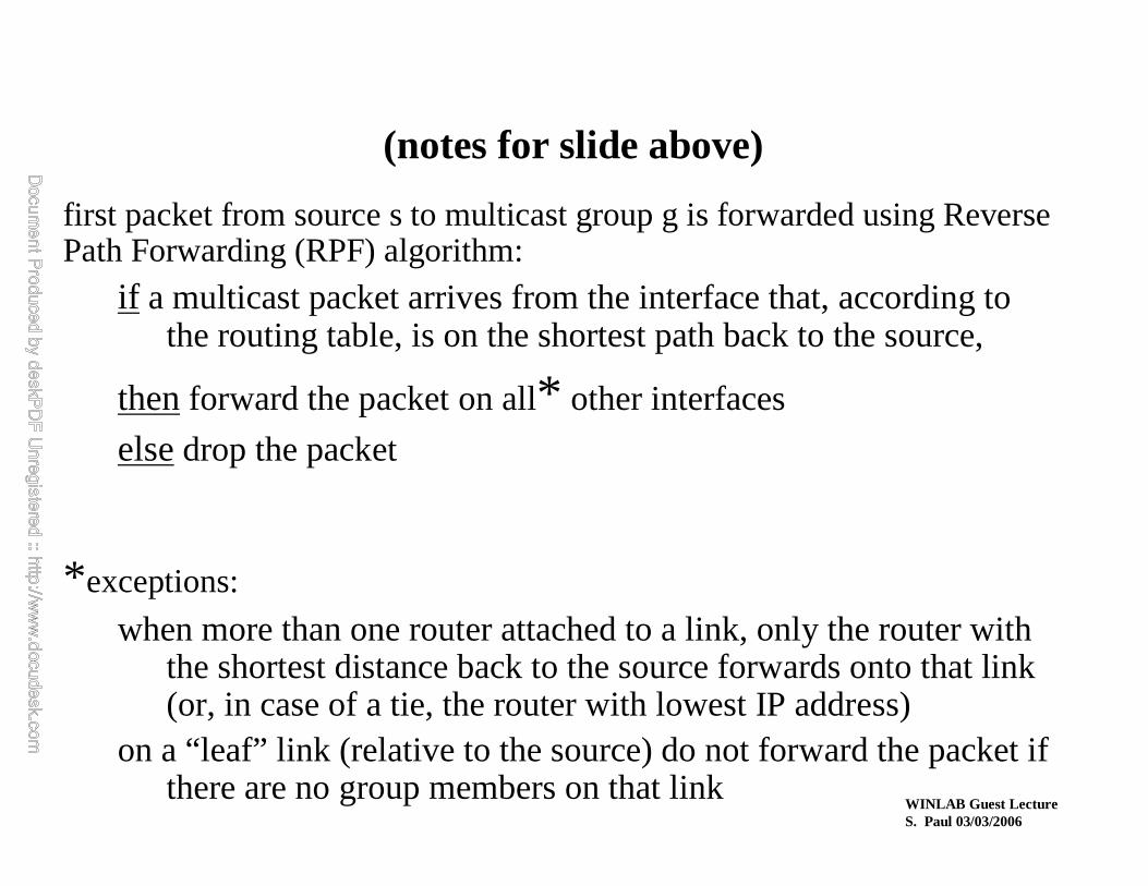
first packet from source s to multicast group g is forwarded using Reverse Path Forwarding (RPF) algorithm:
if a multicast packet arrives from the interface that, according to the routing table, is on the shortest path back to the source,
thenforward the packet on all* other interfaces
elsedrop the packet
*exceptions:
when more than one router attached to a link, only the router with the shortest distance back to the source forwards onto that link(or, in case of a tie, the router with lowest IP address)
on a “leaf” link (relative to the source) do not forward the packet if there are no group members on that link
(notes for slide above)

WINLAB Guest LectureS. Paul 03/03/2006
Phase 2: Pruning
g g
s
prune (s,g)
prune (s,g)
g

WINLAB Guest LectureS. Paul 03/03/2006
when a packet reaches a router for whom there are no permitted outgoing interfaces, that router sends a prunemessage to its predecessor on the path back to the source
if the reception of a prune message causes predecessor now to have no remaining outgoing interfaces, it then sends a prune message to itspredecessor
routers keep state remembering what prunes they have sent and received; the state is discarded after a (relatively long) timeout
(notes for slide above)
WIN
LAB
Gue
st L
ectu
reS
. P
aul 0
3/03
/200
6
Ste
ady
Sta
te
gg
s
g
g
WINLAB Guest LectureS. Paul 03/03/2006
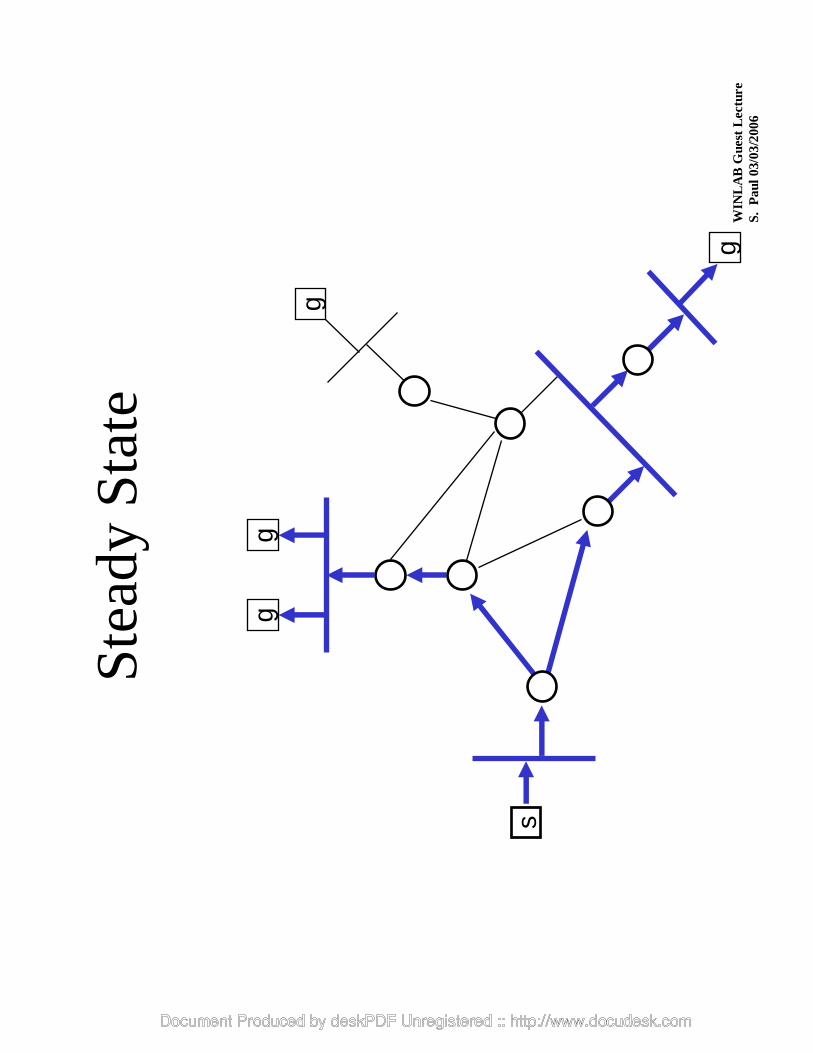
now, packets flow down only those branches that lead to members of the multicast group
when the prune-state times out, if there is still multicast traffic from s to g, truncated broadcast happens again, triggering prunes again;if the traffic has stopped, nothing more happens and no state remains for traffic from s to g
(notes for slide above)
WINLAB Guest LectureS. Paul 03/03/2006
graft (s,g)
graft (s,g)
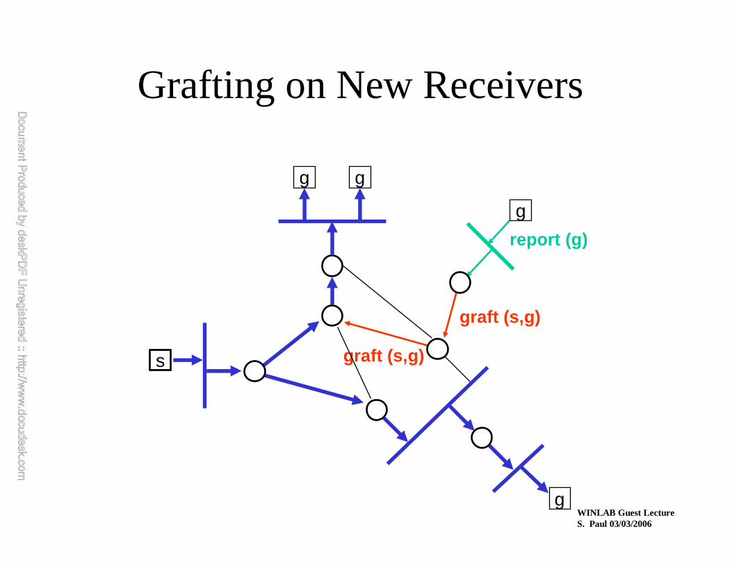
Grafting on New Receivers
g g
s
g
g
report (g)

WINLAB Guest LectureS. Paul 03/03/2006
if a new group member appears on a pruned-off link (as detected by IGMP), the upstream router for that link sends graft messages to undo the effect of any prune messages sent, regarding that group
(notes for slide above)

WINLAB Guest LectureS. Paul 03/03/2006
Steady State after Grafting
g g
s
g
g

WINLAB Guest LectureS. Paul 03/03/2006
• DVMRP works
–DVMRP is good for dense groups (most end-users in a network are members)
• DVMRP is inefficient for sparse groups
• DVMRP does not scale for groups with geographically distributed members
• DVMRP requires RIP as the unicast routing protocol
» This led to the development of new multicast routing protocols:
— Core-Based Tree (CBT) -- RFC-2189
— Protocol Independent Multicast-Sparse Mode (PIM-SM) -- RFC-2362
Discussion on DVMRP

WINLAB Guest LectureS. Paul 03/03/2006
Topology to Illustrate Types ofDelivery Trees
R1
S1
R2
S2
R4
R3

WINLAB Guest LectureS. Paul 03/03/2006
Unidirectional Tree,One Tree Per Source
R1
S1
R2
S2/R5
R4
R3

WINLAB Guest LectureS. Paul 03/03/2006
Unidirectional Tree,Shared by All Sources
R1
S1
R2
S2/R5
R4
R3

WINLAB Guest LectureS. Paul 03/03/2006
Bi-directional Tree,Shared by All Sources
R1
S1
R2
S2/R5
R4
R3

WINLAB Guest LectureS. Paul 03/03/2006
How to Find the Sources?
• broadcast everywhere –DVMRP/PIM-DM– receivers decide when they do not want the traffic
�use a rendezvous point (RP) –PIM-SM/CBT– receivers send joins along reverse path to RP
– sources send traffic to RP
• require receivers to already know source(s) --SSM– use some out-of-band mechanism

WINLAB Guest LectureS. Paul 03/03/2006
Protocol Independent Multicast (PIM)• “Protocol Independent”
– does not perform its own routing information exchange
– uses unicast routing table made by any of the existing unicast routing protocols
• PIM-DM (Dense Mode) - similar to DVMRP, but:– without the routing information exchange part
– differs in some minor details
• PIM-SM (Sparse Mode), or just PIM - instead of directly building per-source, shortest-path trees:
– initially builds a single (unidirectional) tree per group , shared by all senders to that group
– once data is flowing, the shared tree can be converted to a per-source, shortest-path tree if needed

WINLAB Guest LectureS. Paul 03/03/2006
PIM Protocol Overview
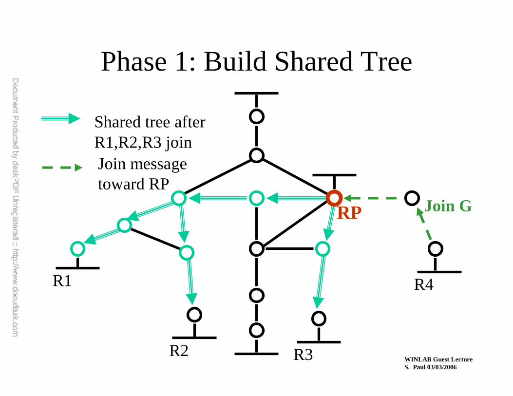
• Basic protocol steps– routers with local members send Join messages towards a
Rendezvous Point (RP) to join shared tree
– routers with local sources encapsulate data to RP
– routers with local members may initiate data-driven switch to source-specific, shortest-path tree
• IETF PIM WG started in Aug’98 to standardize PIM– http://www.ietf.org/html.charters/pim-charter.html
WINLAB Guest LectureS. Paul 03/03/2006
RP
R1
R2 R3
R4
Join messagetoward RP
Shared tree after R1,R2,R3 join
Phase 1: Build Shared Tree
Join G

WINLAB Guest LectureS. Paul 03/03/2006
Phase 2: Sources Send to RP
RP
R1
R2 R3
R4
S1
unicast encapsulateddata packet to RP
RP decapsulates,forwards downShared treeS2

WINLAB Guest LectureS. Paul 03/03/2006
Phase 3: Stop Encapsulation
RP
R1
R2 R3
R4
S1
Join G for S1Join G for S2S2
(S1,G)
(S1,G)(S2,G)
(*.G)

WINLAB Guest LectureS. Paul 03/03/2006
Phase 4: Switch to Shortest Path Tree
R1
R2 R3
R4
Join messagestoward S2
shared tree
S1
S2
RP

WINLAB Guest LectureS. Paul 03/03/2006
Phase 5: Prune (S2 off) Shared Tree
R1
R2 R3
R4
S1
S2 distribution treeShared tree
Prune S2 off Shared tree where iif of S2 andRP entries differS2
RP

WINLAB Guest LectureS. Paul 03/03/2006
RP Mechanism
• end-systems only need multicast address to send or receive
• routers use algorithmic mapping of group address to RP from manageably-small set of RPs known throughout region
• consistent RP mapping and adaptation to failures is CRITICAL
– all routers (within PIM region) must associate a single active RP with a multicast group
• optimal RP location not necessary

WINLAB Guest LectureS. Paul 03/03/2006
RP Mechanisms — Overview
• each candidate RP periodically indicates liveness to Bootstrap Router in the PIM region
• Bootstrap Router periodically distributes set of reachable candidate RPs to all PIM routers in region
– like unicast routing—track liveness continuously, not on demand
• each PIM router uses the same hash function and set of RPs to map a particular multicast group address to that group’s RP.

WINLAB Guest LectureS. Paul 03/03/2006
Bootstrap Router
• Bootstrap Router function– construct set of RPs (RP set) based on
Candidate RP advertisements
– periodically distribute RP set in Bootstrap messages to all routers in region by hop-by-hop flooding
• Bootstrap Router should be well-connected for stability, and dynamically elected for robustness

WINLAB Guest LectureS. Paul 03/03/2006
Bootstrap Router Election
• simple bridge-like spanning-tree election algorithm
• candidate Bootstrap Routers originate PIM hop-by-hop Bootstrap messages with IP address and configurable preference value.
• Bootstrap messages exchanged by all PIM routers within region
• most preferred (or highest numbered) reachable candidate Bootstrap Router elected
• sent periodically and triggered

WINLAB Guest LectureS. Paul 03/03/2006
All routers use hash function tomap Group Address to RP
• hash function – input: group address G and address of each
candidate RP in RP set (optional Mask)
– output: Value computed per candidate RP in RP set
– RP with highest value is the RP for G
• desirable characteristics– minimize remapping when RP reachability changes
— remap only those that lost RP
– load spreading of groups across RPs

WINLAB Guest LectureS. Paul 03/03/2006
• Core-Based Tree (CBT)
— CORE
IP Multicast Routing- CBT
Sender
Receiver
Receiver
Receiver
Join Message:
Receiver
CORE
J
J
J J
J
J
J
Router
Sender
Receiver
SS

• Core-Based Tree (CBT)
— bi-directional shared tree
IP Multicast Routing- CBT
Sender
Receiver
Receiver
Receiver
Multicast Tree:
Receiver
CORE
Router
Sender
Receiver
SS
• Multicast Extensions to OSPF (MOSPF) -- RFC-1584
— Adds Group-Membership-Link-State-Advertisement to OSPF
— Computes shortest path tree rooted at the sender based on groupmembership info
— Requires OSPF as the underlying unicast routing protocol
— Does not scale with the size of network
IP Multicast Routing- MOSPF

WINLAB Guest LectureS. Paul 03/03/2006
Inter-Domain MulticastRouting Protocols
WINLAB Guest LectureS. Paul 03/03/2006
Components of theIP Multicast Architecture
hosts
routers
service model
host-to-router (IGMP)
intra-domain routing
inter-domain routing

WINLAB Guest LectureS. Paul 03/03/2006
What Exactly is Needed?
• inter-domain route exchange protocol
• mechanism for connecting domains– two models:
• discover sources using “source announcing” protocol
• know the source(s) a priori

WINLAB Guest LectureS. Paul 03/03/2006
Inter-Domain Route Exchange
• Exchange multicast reachability between Autonomous Systems (AS)
– Just like unicast routes are exchanged with BGP
– Protocol is “Multiprotocol extensions to BGP” (RFC 2283)• Also known as “Multicast” BGP (MBGP)
• Also known as BGP4+
• MBGP is available and deployed today.– Multiple vendors: Juniper, Cisco, Nortel, etc.
• Note: Not to be confused with BGMP
WINLAB Guest LectureS. Paul 03/03/2006
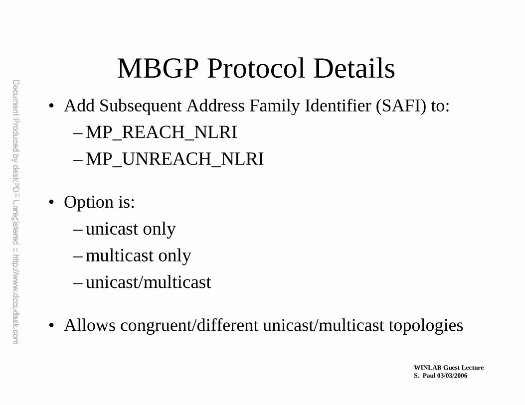
MBGP Protocol Details• Add Subsequent Address Family Identifier (SAFI) to:
– MP_REACH_NLRI
– MP_UNREACH_NLRI
• Option is:
– unicast only
– multicast only
– unicast/multicast
• Allows congruent/different unicast/multicast topologies

WIN
LAB
Gue
st L
ectu
reS
. P
aul 0
3/03
/200
6

WINLAB Guest LectureS. Paul 03/03/2006
What Exactly is Needed?
• inter-domain route exchange protocol
• mechanism for connecting domains– two models:
• discover sources using “source announcing” protocol• know the source(s) a priori

WINLAB Guest LectureS. Paul 03/03/2006
The Internet Solution
• Re-use existing protocols/solutions– Use PIM-SM in the inter-domain
• The challenge is to avoid “root dependencies”– A root/RP/core is in one domain but no active group
participants (sources or receivers) in the domain
– Root dependencies can lead to political problems and inefficiencies

WINLAB Guest LectureS. Paul 03/03/2006
The Internet Solution (cont)
• The key: Establish a root/RP/core per domain– No “root dependencies”
• Remember the problem:– Connecting sources and receivers
– Solution is to use Multicast Source Discovery Protocol (MSDP)
• MSDP is the last piece of the puzzle; is simple to implement; and yields an interim solution to inter-domain multicast

WIN
LAB
Gue
st L
ectu
reS
. P
aul 0
3/03
/200
6

WINLAB Guest LectureS. Paul 03/03/2006
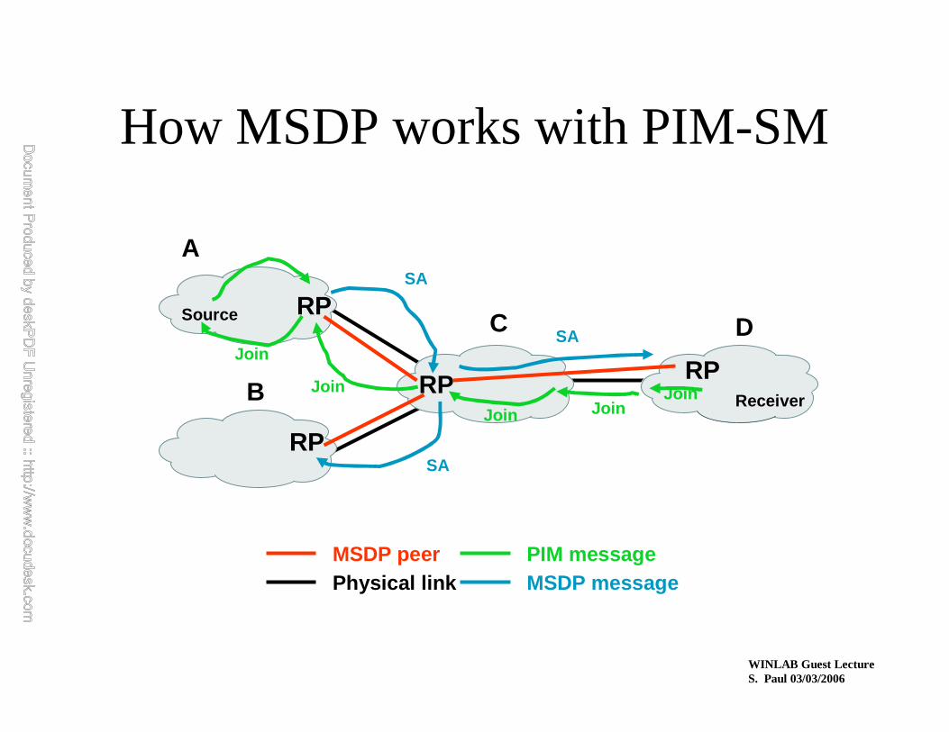
MSDP -- Basic Idea
• MSDP advertises multicast sources to other domains
• Other domains decide if group members are active and find a way to get the data
• “MSDP connects shared-trees together”
• MSDP typically runs in the RP

WINLAB Guest LectureS. Paul 03/03/2006
MSDP - Elements of Operation
• Receivers in a domain join the shared-tree
• The RP is known only to routers in the domain
• When a source goes active in a domain, it’s packets get to the RP in that domain
• The RP sends a Source-Active (SA) message identifying the source and group it sends to

WINLAB Guest LectureS. Paul 03/03/2006
MSDP - Elements of Operation (cont)
• How to get SA messages to all MSDP peers?
– Need MSDP topology flooding protocol
– The RP’s address is also in the SA message to accommodate “peer-RPF” like flooding
– Each MSDP peer receives SA message and forwards away from the originating RP

WINLAB Guest LectureS. Paul 03/03/2006
MSDP - Elements of Operation (cont)
• Each MSDP speaking RP will examine SA message to see if any local members are joined to the group
• If so, the RP joins to source described in SA message
• Otherwise, the SA message is ignored (Flood-and-Join model)
WINLAB Guest LectureS. Paul 03/03/2006
How MSDP works with PIM-SM
RP
RP
RP
RP
MSDP peerPhysical link
A
B
C D
Receiver
Source
PIM messageMSDP message
SA
SA
SA
JoinJoinJoin
Join
Join

WINLAB Guest LectureS. Paul 03/03/2006
What Exactly is Needed?
• inter-domain route exchange protocol
• mechanism for connecting domains– two models:
• discover sources using “source announcing” protocol
• know the source(s) a priori—SSM model

WINLAB Guest LectureS. Paul 03/03/2006
Source Specific Multicast (SSM)
• Basic idea:– Assumes receiver knows the source(s)
– Reverse SPT join to source• No RPs or MSDP
– About as straightforward as you can get!

WINLAB Guest LectureS. Paul 03/03/2006
How SSM Works
Physical link
A
B
C D
Receiver
Source
PIM message
JoinJoinJoin
Join
Join
Join

WINLAB Guest LectureS. Paul 03/03/2006
Source Specific Multicast• Advantages
– Minor changes to existing infrastructure—still use PIM-SM
– No PIM-SM RP, or MSDP
• Limitations– Requires modifications (last hop routers) and IGMPv3
– May be difficult to support some applications
• Thoughts– Works for 9x% of killer-apps -- need mechanism (WWW) to
let receivers know who sources are
– Success will depend on seamless migration strategy

WINLAB Guest LectureS. Paul 03/03/2006
•Mbone consists of IP Tunnels
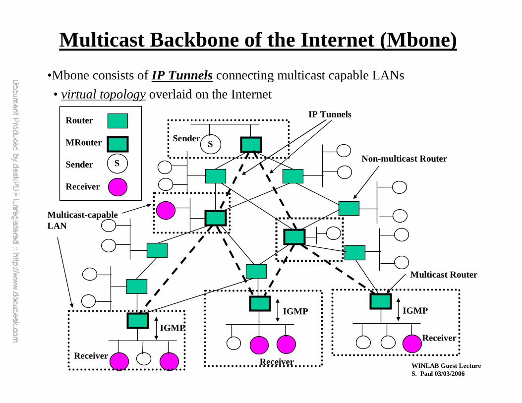
Multicast Backbone of the Internet (Mbone)
M1 M2
R1 R2
M1 M2 M1 224.4.4.4
Original IP Multicast PacketOuter IP Hdr
IP TUNNEL
M1
R1
MULTICAST-CAPABLE ROUTER:
REGULAR ROUTER:
Actual path takenby the IP Packet
Encapsulation Decapsulation
WINLAB Guest LectureS. Paul 03/03/2006
•Mbone consists of IP Tunnelsconnecting multicast capable LANs
• virtual topologyoverlaid on the Internet
Multicast Backbone of the Internet (Mbone)
Sender
ReceiverReceiver
Receiver
Router
MRouter
Sender
Receiver
S
S
IP Tunnels
IGMP
IGMP IGMP
Non-multicast Router
Multicast Router
Multicast-capableLAN

WIN
LAB
Gue
st L
ectu
reS
. P
aul 0
3/03
/200
6
MB
on
eT
op
olo
gy in
200
1
WINLAB Guest LectureS. Paul 03/03/2006
• PartPart--I: Multicasting FundamentalsI: Multicasting Fundamentals
• PartPart--II: IP MulticastII: IP Multicast
» Part-III: Reliable Multicast Transport Protocols
•• PartPart--IV: Multicast Congestion ControlIV: Multicast Congestion Control
WINLAB Guest LectureS. Paul 03/03/2006
� Fundamental Problems
• Scalable Reliable Multicast (SRM)
• Reliable Multicast Transport Protocol (RMTP)
• Forward Error Correction (FEC) and Reliable Multicast
• Pretty Good Multicast (PGM)
Reliable Multicast
Reliable Multicast
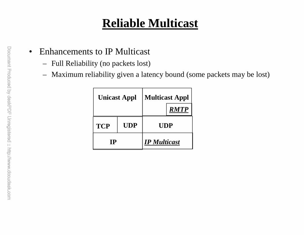
• Enhancements to IP Multicast– Full Reliability (no packets lost)
– Maximum reliability given a latency bound (some packets may be lost)
IP IP Multicast
TCP UDP
Unicast Appl Multicast Appl
UDP
RMTP
FundamentalProblems
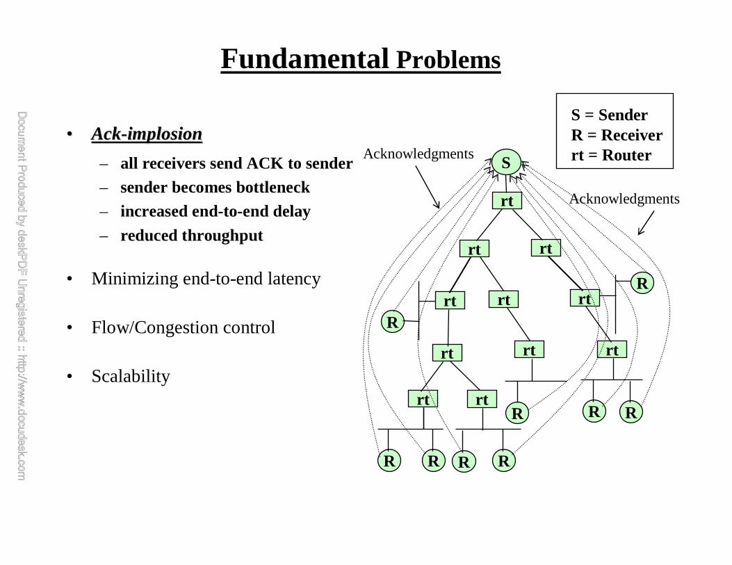
Acknowledgments
Acknowledgments
S = SenderR = Receiverrt = RouterS
rt
rt
rt
rt rt
rt
rt
rt rt
rt
R
rt
R
R R R R
R RR
•• AckAck--implosionimplosion
– all receivers send ACK to sender– sender becomes bottleneck– increased end-to-end delay
– reduced throughput
• Minimizing end-to-end latency
• Flow/Congestion control
• Scalability
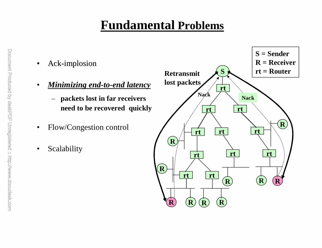
FundamentalProblems
S
rt
rt
rt
rt rt
rt
rt
rt rt
rt
R
rt
R
R R R R
R RR
R
Retransmitlost packets
NackNack
S = SenderR = Receiverrt = Router
•• AckAck--implosionimplosion
• Minimizing end-to-end latency
– packets lost in far receivers need to be recovered quickly
• Flow/Congestion control
• Scalability

FundamentalProblems
S
rt
rt
rt
rt rt
rt
rt
rt rt
rt
R
rt
R
R R R R
R RR
S = SenderR = Receiverrt = Router
•• AckAck--implosionimplosion
• Minimizing end-to-end latency
• Flow/Congestion control
– feedback implosion– what window size at sender?
• Scalability
Congestedlinks

WINLAB Guest LectureS. Paul 03/03/2006
• Fundamental Problems
� Scalable Reliable Multicast (SRM)
• Reliable Multicast Transport Protocol (RMTP)
• Forward Error Correction (FEC) and Reliable Multicast
• Pretty Good Multicast (PGM)
Reliable Multicast

Scalable Reliable Multicast (SRM)
• Based on Floyd, Jacobsen, McCanne’s work
(SIGCOMM ‘95)
• Many-to-many reliable multicast
• Key ideas:
– Application-level Framing (ALF)
– Out-of-order reliable delivery
– NAK-based
– Receiver-based reliability
– NAKs and Repairs are both multicast
• Protocol:
– Sender transmits packets
– Receiver detects loss and multicastsNAK
– Any receiver with the message multicaststhe
retransmission
Missing Parts
Illustration of shared whiteboard

How does SRM solve Ack-implosion?
• Does not use “Acks”
• Uses NAKs
– generated on packet loss only
• What about NAK-implosion?
– NAK implosion happens at all
receivers in addition to the sender
• Need for NAK suppressionWorst Scenario:everyone NAKs
NAK implosion

Ideal NAK Suppression
Ideal Scenario:single NAK
NAKs
• Single NAK should suppress all others
• Randomly delay NAKs and shut up on receiving the same NAK
• How long should one wait before sending NAK?
– Uniform distribution in the interval [c1*ds,a, (c1+c2)*ds,a] where “s” is the source of data and “a” is the receiver which missed a packet and ds,a is the one-way delay between “s” and “a”.
• Each receiver needs one-way delay from every sender

Real-world NAK Suppression
• Delay estimates are not accurate
• Constants “c1” and “c2” depend on the
actual topology of the network over
which the receivers are distributed
• Imperfect NAK suppression
Better Scenario:some members NAK
NAK implosion
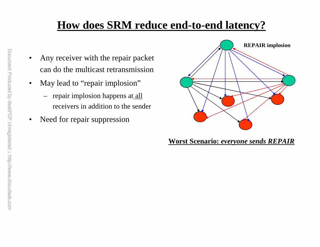
How does SRM reduce end-to-end latency?
• Any receiver with the repair packet
can do the multicast retransmission
• May lead to “repair implosion”
– repair implosion happens at all
receivers in addition to the sender
• Need for repair suppression
Worst Scenario:everyone sends REPAIR
REPAIR implosion

Ideal Repair Suppression
• Single “repair” should suppress all others
• Schedule repair timers and retransmit when timer expires unless someone has already done the retransmission.
• How long should one wait before sending repair?
– Uniform distribution in the interval [d1*da,b, (d1+d2)*da,b] where “a” is the NAK generator and “b” is a receiver with the repair packet and da,b is the one-way delay from “b” to “a”.
• Each receiver needs one-way delay from every otherreceiver
Ideal Scenario:single REPAIR
REPAIRs
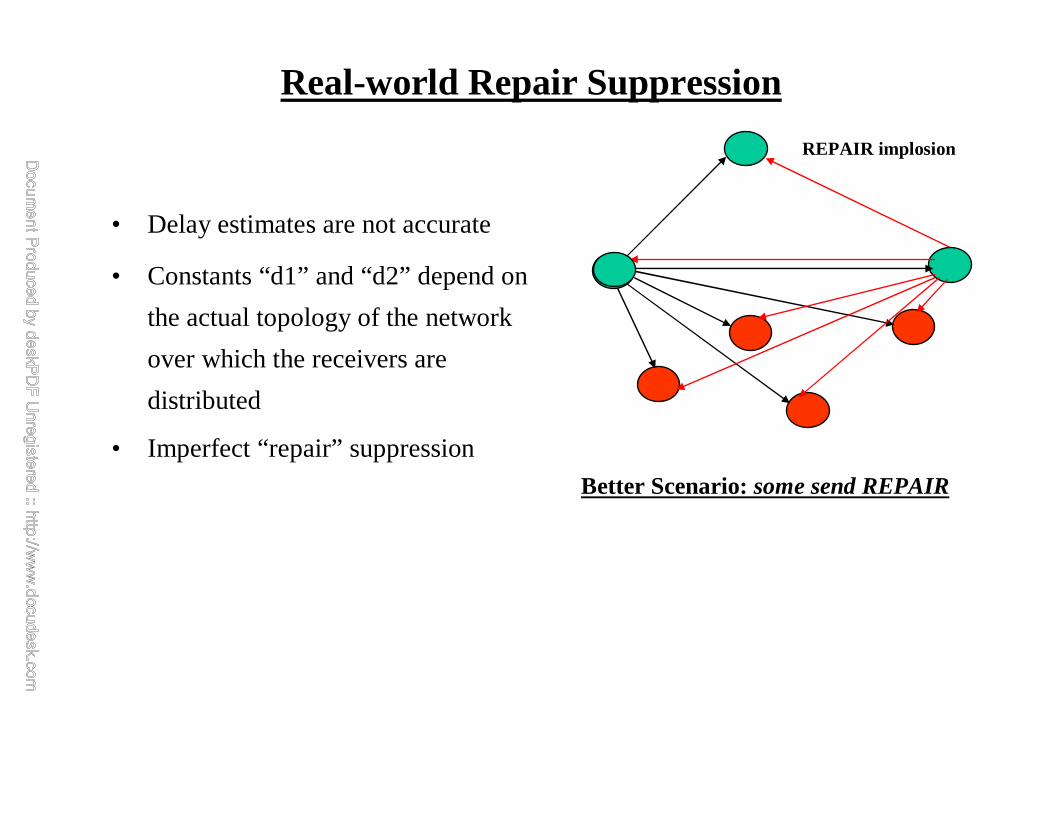
Real-world Repair Suppression
• Delay estimates are not accurate
• Constants “d1” and “d2” depend on
the actual topology of the network
over which the receivers are
distributed
• Imperfect “repair” suppression
Better Scenario:some send REPAIR
REPAIR implosion

Scalability of SRM
Self-organization of receivers
• All pairs round-trip time estimation
needed for effective NAK suppression
and “repair” suppression
– Not a scalable solution
• New work in SRM focuses on “self
organization” of receivers so that each
receiver needs to maintain round-trip
time estimates for a small subset

WINLAB Guest LectureS. Paul 03/03/2006
• Fundamental Problems
• Scalable Reliable Multicast (SRM)
� Reliable Multicast Transport Protocol (RMTP)
• Forward Error Correction (FEC) and Reliable Multicast
• Pretty Good Multicast (PGM)
Reliable Multicast

Reliable Multicast Transport Protocol (RMTP)
• Groups receivers into “local regions” with a
DR in each region
• Organizes the DRs in a logical hierarchy
• Transmission by Sender
• Acks from R to DR
• Acks from DR to S or DR
• Retransmission by DR
S
rt
rt
rt
rt rt
rt
rt
rt rt
rt
DR
rt
DR
R R R
R R RR
Acknowledgments
Acknowledgments
DR
R
DR
D D
D DD
D D D
DD
D D
D D
S = SenderR = Receiverrt = Router
DR = Designated Receiver

How does RMTP solve Ack-implosion?
• Divide and Conquer
— Acks from R to DR
— Acks from DR to S or DR
• Sender receives as many Acks
as there are top-level DRs
S
rt
rt
rt
rt rt
rt
rt
rt rt
rt
DR
rt
DR
R R R
R R RR
Acknowledgments
DR
R
DR
D D
D DD
D D D
DD
D D
D D
S = SenderR = Receiverrt = RouterDR = DesignatedReceiver

How does RMTP minimize end-to-end latency?
• Local Recovery
• Retransmission by a DR
• Retransmission request
(Nack) from R to DR
S
rt
rt
rt
rt rt
rt
rt
rt rt
rt
DR
rt
DR
R R R
R R RR
DR
R
DR
D D
D DD
D D D
DD
D D
D DNack
Retransmission
S = SenderR = Receiverrt = RouterDR = DesignatedReceiver

Flow control and Congestion control in RMTP
• DR sends congestion feedback
– solves feedback implosion
• Separate window for each
receiver
• Subject both transmitted and
retransmitted packets to flow
control
S
rt
rt
rt
rt rt
rt
rt
rt rt
rt
DR
rt
DR
R R R
R R RR
DR
R
DR
D D
D DD
D D D
DD
D D
D D
Congestion feedback
Congestedarea
S = SenderR = Receiverrt = RouterDR = DesignatedReceiver

Recovery Strategy and Robustness of RMTP
• Receivers switch to next-level
DR if current DR fails
• Primary and Backup Sender
S
rt
rt
rt
rt rt
rt
rt
rt rt
rt
DR
rt
DR
R R R
R R RR
Acknowledgments
DR
R
DR
D D
D DD
D D D
DD
D D
D D
S = SenderR = Receiverrt = RouterDR = DesignatedReceiver
DR Failure
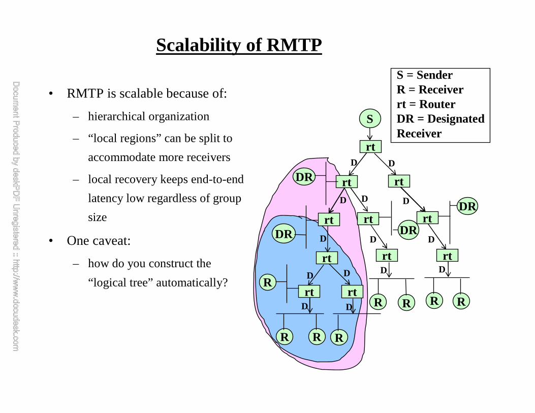
Scalability of RMTP
• RMTP is scalable because of:
– hierarchical organization
– “local regions” can be split to
accommodate more receivers
– local recovery keeps end-to-end
latency low regardless of group
size
• One caveat:
– how do you construct the
“logical tree” automatically?
S
rt
rt
rt
rt rt
rt
rt
rt rt
rt
DR
rt
DR
R R R
R R RR
DR
R
DR
D D
D DD
D D D
DD
D D
D D
S = SenderR = Receiverrt = RouterDR = DesignatedReceiver
WINLAB Guest LectureS. Paul 03/03/2006
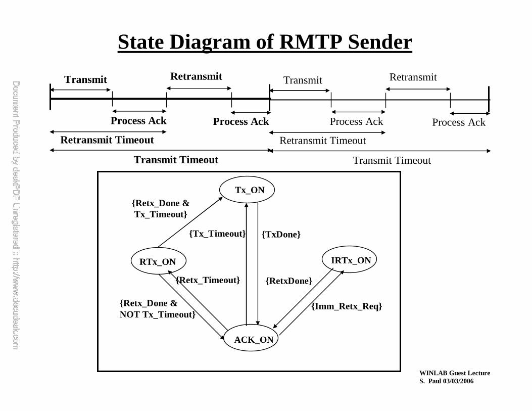
State Diagram of RMTP Sender
Transmit
Process Ack
Retransmit
Process Ack
Retransmit Timeout
Transmit Timeout
Transmit
Process Ack
Retransmit
Process Ack
Retransmit Timeout
Transmit Timeout
Tx_ON
RTx_ON IRTx_ON
ACK_ON
{Tx_Timeout} {TxDone}
{RetxDone}
{Imm_Retx_Req}{Retx_Done &NOT Tx_Timeout}
{Retx_Timeout}
{Retx_Done &Tx_Timeout}
WINLAB Guest LectureS. Paul 03/03/2006
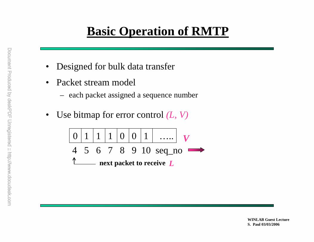
Basic Operation of RMTP
• Designed for bulk data transfer
• Packet stream model– each packet assigned a sequence number
• Use bitmap for error control (L, V)
0 1 111 0 0 …..
4 85 6 7 9 10 seq_nonext packet to receive
V
L
WINLAB Guest LectureS. Paul 03/03/2006
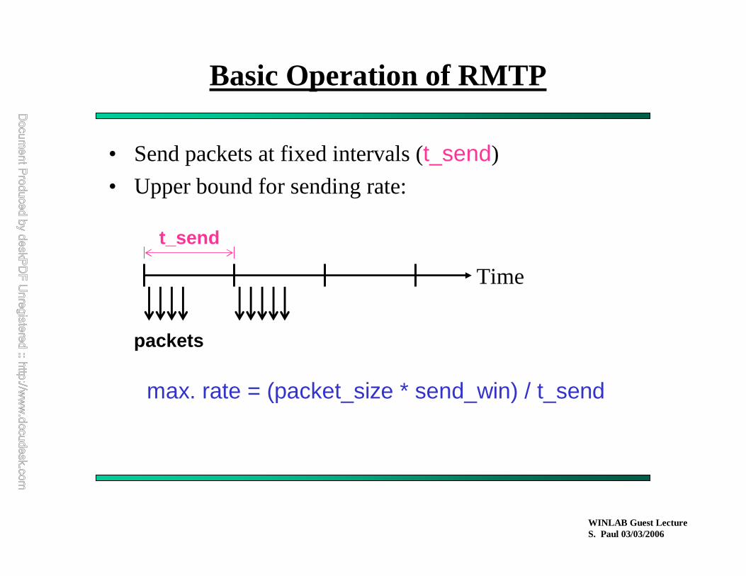
Basic Operation of RMTP
• Send packets at fixed intervals (t_send)
• Upper bound for sending rate:
Time
t_send
packets
max. rate = (packet_size * send_win) / t_send

WINLAB Guest LectureS. Paul 03/03/2006
Example to Illustrate RMTP Execution
Send Window = 16,Mcast_Thresh = 1S
R1
R2
R3
1, . . ., 16Retransmit (8,10)
Retransmit (5,10)
Retransmit (8,14)
R3 R1, R2 R2, R3 R1
1 2 2 1
14 10 8 5 Packet#
# of Retransmission Request
Address of Requesting Receivers
1 2 3 4 5 6 7 8 9 10 11 12 13 14 15 16
Avail_window
ReXmitQueue
SendWindow

WINLAB Guest LectureS. Paul 03/03/2006
RMTP Implementation Architecture
• User-level protocol process (rmtpd)
ReceiverReceiver
Sender
UDP UDP
rmtpdrmtpd
rmtpd
TCP
TCP TCP

WINLAB Guest LectureS. Paul 03/03/2006
Reliable Multicasting of a File
Application Data Unit (ADU) < ADU size
Application feeding RMTP daemon
t = 0
T_dally< T_dally
Retransmission RequestResets T_dally Timer
Application Data Unit Application Data Unit
Time
Application feeds equal-sized data units to RMTP daemon except for the last chunk

WINLAB Guest LectureS. Paul 03/03/2006
Reliable Multicasting of a Continuous Stream
BLOCK # 1
Application feeding RMTP daemon
t = 0
< T_dally T_dally T_dally
BLOCK # 2 BLOCK # 3 BLOCK # 4
Time Retransmission Requestresets T_dally Timer
. . .
EOB EOB EOB EOB
DRAWBACK: Sender waits for T_dally at the end of “every” block leading to low throughput
WHY? Neither the sender nor the DRs keep track of “membership” info
Application chops a stream into “blocks” and RMTP uses T_dally at the end of each block
WINLAB Guest LectureS. Paul 03/03/2006
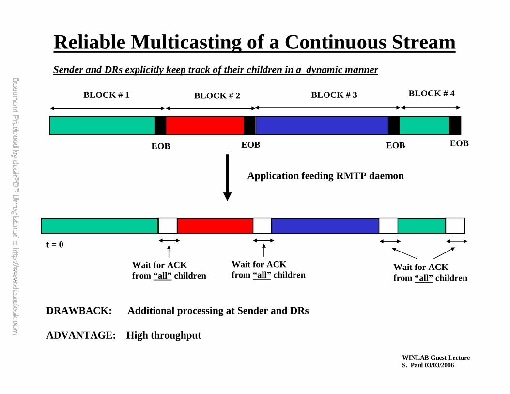
Reliable Multicasting of a Continuous Stream
BLOCK # 1
Application feeding RMTP daemon
t = 0
BLOCK # 2 BLOCK # 3 BLOCK # 4
EOB EOB EOB EOB
DRAWBACK: Additional processing at Sender and DRs
ADVANTAGE: High throughput
Wait for ACKfrom “all” children
Wait for ACKfrom “all” children
Wait for ACKfrom “all” children
Sender and DRs explicitly keep track of their children in a dynamic manner
WINLAB Guest LectureS. Paul 03/03/2006
RMTP Status
- Used in AT&T’s billing networksince 7/96
- Licensed the technology to GlobalCastInc. (start-up in California) 7/97
- Used in distance learning system called IRI (Interactive Remote Instruction)
- Being used by Dow Jones Teleratefor market data distribution
- Was proposed as an Internet standard (first Internet draft-- March 1998) and
key ideas adopted in Reliable Multicast RFCs
- RMTP used in Web Caching solution from Lucent Technologies (IPWorX)

WINLAB Guest LectureS. Paul 03/03/2006
• Fundamental Problems
• Scalable Reliable Multicast (SRM)
• Reliable Multicast Transport Protocol (RMTP)
� Forward Error Correction (FEC) and Reliable Multicast
• Pretty Good Multicast (PGM)
Reliable Multicast

WINLAB Guest LectureS. Paul 03/03/2006
Forward Error Correction and Reliable Multicast Transmission
• Nonnenmacher, Biersack and Towsley in SIGCOMM’97
showed how reliable multicast can be made scalable by
incorporating forward error correction (FEC)
• Key idea:
– proactively send parity packets with regular data packets
– loss of limited number of packets can be recovered using
the redundant packets
– reduces retransmissions
– improves latency (useful for delay-sensitive traffic)

WINLAB Guest LectureS. Paul 03/03/2006
How Forward Error Correction works
• Parameters:
– k original data packetsform a transmission group (TG)
k = 3 in the above example
– h parity packets derived from the k data packets
h = 2 in the above example
– any k received out of k+h are sufficient
FECEncoder
D2 D1D3
P1P2
D2 D1D3P1P2
FECDecoder
P2 D3
D2 D1Loss in FEC Block
D2 D1D3

WINLAB Guest LectureS. Paul 03/03/2006
Why FEC for Reliable Multicast
• A single parity packetcan repair the loss of differentdata
packets at differentreceivers
S
R1
R2
R3D2 D1D3
D2 D1D3
D2 D1D3
First Transmission S
R1
R2
R3D2 D1D3
D2 D1D3
D2 D1D3
Data Retransmission
S
R1
R2
R3P
Parity Retransmission
P
PP = D1 xor D2 xor D3
WINLAB Guest LectureS. Paul 03/03/2006
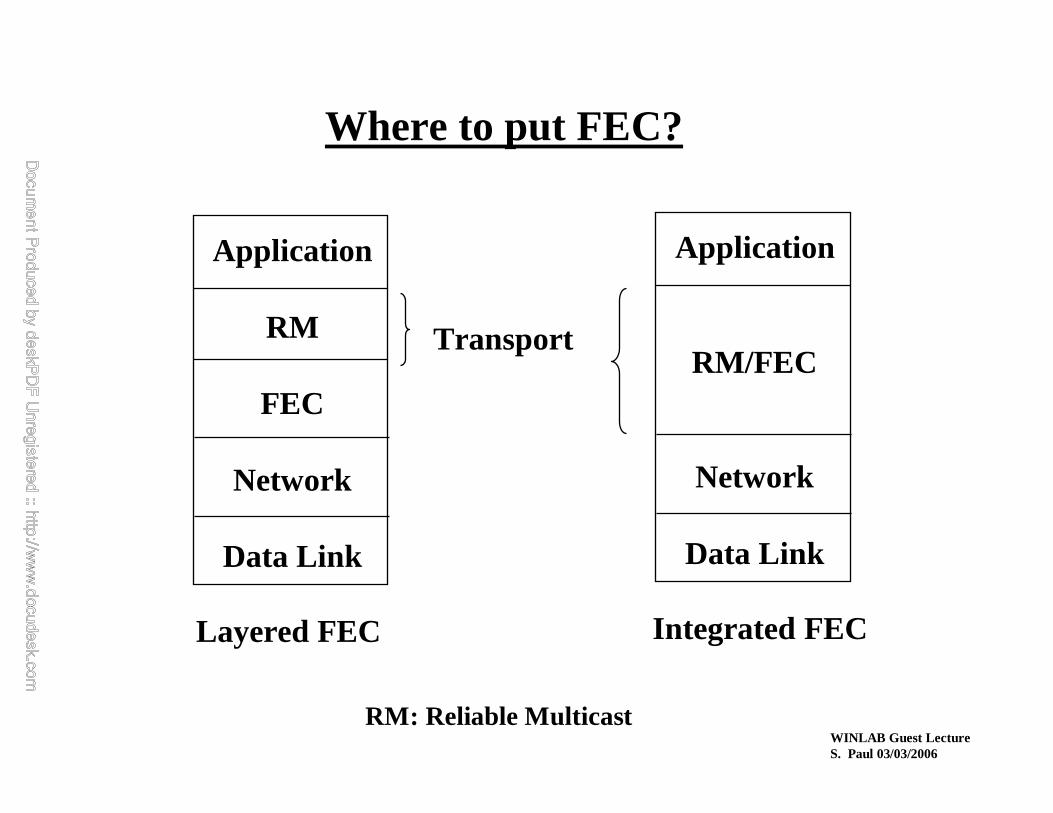
Where to put FEC?
Application
RM
FEC
Network
Data Link
Application
RM/FEC
Network
Data Link
Layered FEC Integrated FEC
RM: Reliable Multicast
Transport
WINLAB Guest LectureS. Paul 03/03/2006
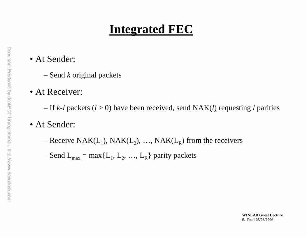
Integrated FEC
• At Sender:
– Send k original packets
• At Receiver:
– If k-l packets (l > 0) have been received, send NAK(l) requesting l parities
• At Sender:
– Receive NAK(L1), NAK(L2), …, NAK(LR) from the receivers
– Send Lmax = max{L1, L2, …, LR} parity packets

WINLAB Guest LectureS. Paul 03/03/2006
Cost of FEC Computation
• Network benefits from reduced number of transmissions due to
integrated FEC
� But FEC isnot for free
• Processing cost
– How fast can the coding/decoding be done?
– What is the throughput of a protocol based on integrated FEC?

WINLAB Guest LectureS. Paul 03/03/2006
Summary of FEC & RM
• Integrated FEC
– dramatically reduces the number of transmissions
– achieves scalability for large number of receivers (up to 10^6)
– reduces the feedback
• Software FEC for Reliable Multicast is feasible today
• From Nonnenmacher:
¬ FEC is like a wonder under the Christmas tree:
� All children missing different packets are satisfied with a single
common packet
WINLAB Guest LectureS. Paul 03/03/2006
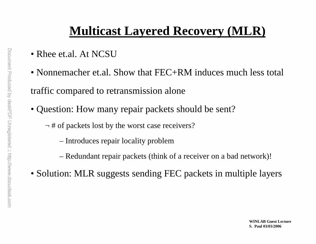
Multicast Layered Recovery (MLR)
• Rhee et.al. At NCSU
• Nonnemacher et.al. Show that FEC+RM induces much less total
traffic compared to retransmission alone
• Question: How many repair packets should be sent?
¬ # of packets lost by the worst case receivers?
– Introduces repair locality problem
– Redundant repair packets (think of a receiver on a bad network)!
• Solution: MLR suggests sending FEC packets in multiple layers

WINLAB Guest LectureS. Paul 03/03/2006
Multicast Layered Recovery (MLR)
• Partitions f FEC repair packets
into K groups: F = {φ1, φ2,…,φK}
• Transmits each group φi using a
different multicast address
• Receivers join or leave multicast groups to match their loss rates
Data FEC repairs
G0
G1
G2
G3

WINLAB Guest LectureS. Paul 03/03/2006
• Fundamental Problems
• Scalable Reliable Multicast (SRM)
• Reliable Multicast Transport Protocol (RMTP)
• Forward Error Correction (FEC) and Reliable Multicast
� Pretty Good Multicast (PGM)
Reliable Multicast

Pretty Good Multicast (PGM)
• Router-assisted reliable multicast
• RFC 3208 (Tony Speakman, Cisco)
• Avoids drawbacks of SRM while
maintains the advantages
– one NAK generated per subnet
– network-level multicast tree
leveraged to do NAK suppression
– subtree multicast is supported for
retransmissions
S
rt
rt
rt
rt rt
rt
rt
rt rt
rt
R
rt
R
R R R
R R R
R
R
R
D D
D
D
D
S = SenderR = Receiverrt = RouterDR = DesignatedReceiver
NAK
NCF
NAK
NCF
NAK NCF
NAKNCFD
D
D
NCF
NCF
NCF

Pretty Good Multicast (PGM)
• Subtree multicast from Designated
Local Retransmitter (DLR)
– minimal redundant retransmissions
– router maintains per lost packet
state
S
rt
rt
rt
rt rt
rt
rt
rt rt
rt
R
rt
R
R R R
R R R
R
R
R
D D
D
D
D
S = SenderR = Receiverrt = RouterDR = DesignatedReceiver
D
D
D
DLR
Retransmissions
WINLAB Guest LectureS. Paul 03/03/2006
• One size does not fit all
• SRM with self-organization + local recovery is best suited for
many-to-many applications
• RMTP is good for one-to-many reliable multicast applications
• FEC is a powerful mechanism which can be combined with either
SRM or RMTP to further improve scalability and efficiency
• Pretty Good Multicast (PGM) leverages state maintained in the
routers to improve the efficiency of reliable multicast protocols
Summary of Reliable Multicast

WINLAB Guest LectureS. Paul 03/03/2006
• Books:
– Multicasting on the Internet and its Applications by Sanjoy Paul (Kluwer Academic Publisher)
• Urls:
– http://catarina.usc.edu/multicast/srm.html
– http://www.east.isi.edu/RMRG/
– http://www.tascnets.com/mist/doc/mcpCompare.html
– http://research.ivv.nasa.gov/RMP/links.html
– http://info.internet.isi.edu:80/in-notes/rfc/files/rfc1889.txt
– http://info.internet.isi.edu:80/in-notes/rfc/files/rfc2326.txt
– http://www.eurecom.fr/~erbi/Bib/bib.html
Useful References

WINLAB Guest LectureS. Paul 03/03/2006
• PartPart--I: Multicasting FundamentalsI: Multicasting Fundamentals
• PartPart--II: IP MulticastII: IP Multicast
• PartPart--III: Reliable Multicast Transport ProtocolsIII: Reliable Multicast Transport Protocols
»» PartPart--IV: Multicast Congestion ControlIV: Multicast Congestion Control

WINLAB Guest LectureS. Paul 03/03/2006
1
Congestion Control in the Internet
Current Limitations:•FIFO queueing prevalent in the Internet routers•No congestion control at the IP layer•No exchange of congestion information among routers or between IP and transport layers
•Packet loss is the main information available to end users about network congestion
�Congestion Control Must be Practiced:•On an end-to-end basis•At the transport layer• Using local loss and and delay observations of each session
� Loss is a good (but not early) indication of congestion, as long as the error rate is not high
� Delay, only when considered on a differential basis, could be
indicative of congestion

WINLAB Guest LectureS. Paul 03/03/2006
2
Components of End-to-End Congestion Control
Regulation Parameter: Rate vs. Window size
– Rate-based regulation:
transmission rate < r
– Window-based regulation:
No. of outstanding packets < w
Regulation Algorithm:
� To adjust rate or window size in response to changing network
conditions
� Ideally, should be based on explicit information about network
congestion status
� In current Internet, could be based on a session’s local
observations about loss and delay
WINLAB Guest LectureS. Paul 03/03/2006
3
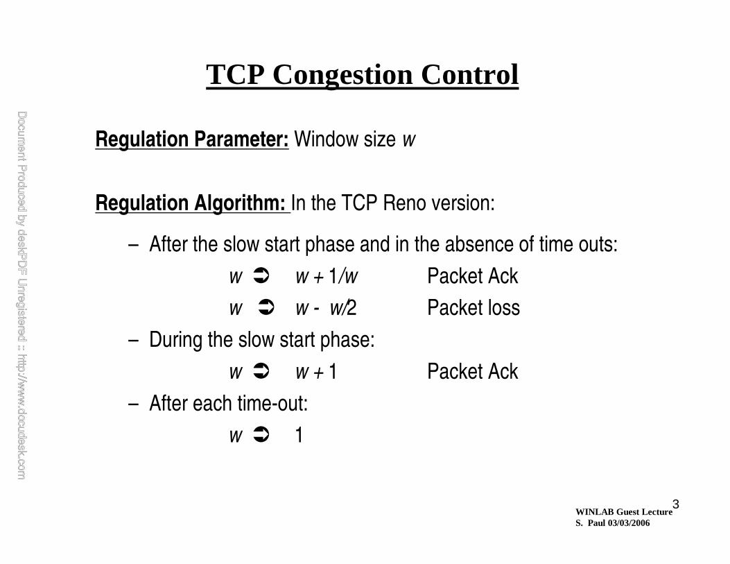
TCP Congestion Control
Regulation Parameter: Window size w
Regulation Algorithm: In the TCP Reno version:
– After the slow start phase and in the absence of time outs:
w � w + 1/w Packet Ack
w � w - w/2 Packet loss
– During the slow start phase:
w � w + 1 Packet Ack
– After each time-out:
w � 1

WINLAB Guest LectureS. Paul 03/03/2006
4
Issues in Multicast Congestion Control
� Rate-based vs. window-based regulation
� Multicast extention of window-based regulation
� Regulation algorithm: how to adjust rate or window size in terms
of loss and delay of various receivers?
Criteria:
– Congestion prevention
– Fairness: How much average throughput should be allowed to
be fair to other sessions?
� What is a good measure of fairness?
– Scalability of throughput: how does the throughput change as
the number of receivers increases.
– Scalability with respect to algorithm complexity and
communication overhead
WINLAB Guest LectureS. Paul 03/03/2006
Issues in Multicast Congestion Control, (cont’d)
� Membership decisions
� Splitting the multicast group into subgroups receiving each data at
a different rate
� Scalable estimation of receiver round trip times
� Intra-session organization of tasks
– Knowledge about receivers
– Nature of application
– Scalability
– Communication overhead associated with the execution of control algorithms

WINLAB Guest LectureS. Paul 03/03/2006
6
Intra-session
Organization
of Tasks
• Scalability
• Reliability
• Communication
Overhead
Error
Control
Data Organization,
Coding & Layering
Traffic Regulation:
– Regulation Parameter
– Regulation Algorithm
•Congestion Prevention•Fairness & Scalability
Group Organization:
– Subgroup Splitting
– Membership Decisions
An Overview of Congestion Control Tasks

WINLAB Guest LectureS. Paul 03/03/2006
7
Window-based Congestion Control
Advantage over Rate-based Congestion Control:
• Even in the absence of a regulation algorithm (fixed w), some degree of protection is provided against congestion:
Increase in RTTτ ⇒ Reduction in throughput R
• Reaction to congestion within one round trip time
• With regulation algorithm based on quasi-static network conditions:– Dynamic control provided by the window mechanism
– Quasi-static control provided by the regulation algorithm
R = wτ

WINLAB Guest LectureS. Paul 03/03/2006
8
Illustration of Window Congestion Control
Token Pool Illustration:�Associate a pool of w tokens with the source.
�One token is consumed for each packet transmission.
� Token is returned once the packet is acknowledged.
�Convenient illustration with out-of-order transmission and acknowledgment.
Sliding Window Illustration:�Based on packet sequence numbers.
�Convenient only when packets are accepted or acknowledged in order.
� Inadequate illustration when packets are selectively retransmitted.
WINLAB Guest LectureS. Paul 03/03/2006
9
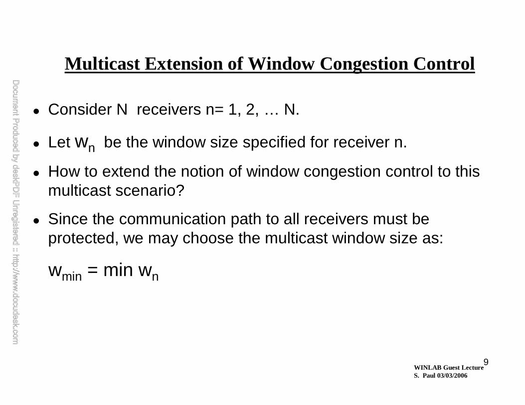
Multicast Extension of Window Congestion Control
� Consider N receivers n= 1, 2, … N.
� Let wn be the window size specified for receiver n.
� How to extend the notion of window congestion control to this multicast scenario?
� Since the communication path to all receivers must be protected, we may choose the multicast window size as:
wmin = min wn

WINLAB Guest LectureS. Paul 03/03/2006
Flow/Congestion Control
• Naïve scheme– sender maintains one token pool with Wmin = min Wn tokens– remove a token each time a packet is multicast– add a token once an Ack is received from everyreceiver
Receiver-1
Receiver-2SenderN = 2W1 = 2W2 = 10Wmin = 2T1 = 1T2 = 10Tmax = 10
Average throughput = Wmin / Tmax = 2/10 = 0.2

WINLAB Guest LectureS. Paul 03/03/2006
Flow/Congestion Control
• One scheme (proposed by Jamal Golestani)– sender maintains N token pools, one per receiver – Wn tokens in the pool corresponding to receiver-n– remove 1 token from each pool when a packet is multicast– add 1 token to pool “n” for each Ack from receiver-n
Receiver-1
Receiver-2SenderN = 2W1 = 2W2 = 10T1 = 1T2 = 10W1/T1 = 2W2/T2 = 1Wmin/Tmax = 0.2
Average throughput = min (Wn / Tn) >> Wmin / Tmax
= min (2/1, 10/10) = min (2, 1) = 1 >> 0.2

WINLAB Guest LectureS. Paul 03/03/2006
Window Congestion Control for Multicast, (cont’d)
Conclusion :
�Must be based on a distinct window size per receiver
– If the the desired throughput R is known, the window size for receiverj , could be set as:
wj = R . τj
�Number of outstanding packets to each receiver must be independently monitored and kept below the corresponding window size.
�Potential scalability problem with regard to processing requirements.

WINLAB Guest LectureS. Paul 03/03/2006
Regulation Algorithm:Fairness and TCP compatibility
� In TCP reno, after the slow start phase and in the absence of time outs:
w � w + 1/w Packet Ack
w � w - w/2 Packet loss
� Average throughput, under favorable assumptions, shown to be:
where 0.9 < c < 1.5, and λ = loss probability
– An approximate relationship
– A statement of fairness
– A measure for checking TCP compatibility
R ≈ c
τ λ

WINLAB Guest LectureS. Paul 03/03/2006
14
A Three-way Design Trade-off
Observed by Jamal Golestani
Consider the following two options in choosing a fairness criterion:
Rate-oriented (RO) Fairness: Throughput independent of RTT
Window-oriented (WO) Fairness: Throughput α 1/RTT
(Average No. of outstanding packets independent of RTT)
Scenarios where RTT is needed:
RO Fairness
WO Fairness
WB Regulation
RB Regulation �
�
� Three way trade-off Btwn:
– Regulation parameter
– Type of fairness
– Need to estimate RTT
WINLAB Guest LectureS. Paul 03/03/2006
15
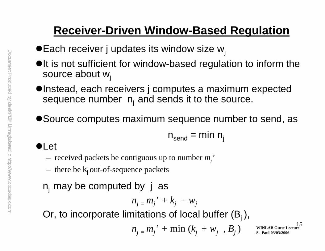
Receiver-Driven Window-Based Regulation
�Each receiver j updates its window size wj
�It is not sufficient for window-based regulation to inform the source about wj
�Instead, each receivers j computes a maximum expected sequence number nj and sends it to the source.
�Source computes maximum sequence number to send, as
nsend = min nj�Let
– received packets be contiguous up to number mj’
– there be kj out-of-sequence packets
nj may be computed by j as nj = mj’ + k j + wj
Or, to incorporate limitations of local buffer (Bj ), nj = mj’ + min (kj + wj , Bj )
WINLAB Guest LectureS. Paul 03/03/2006
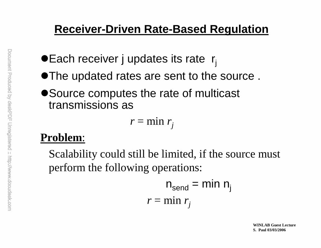
Receiver-Driven Rate-Based Regulation
�Each receiver j updates its rate rj
�The updated rates are sent to the source .
�Source computes the rate of multicast transmissions as
r = min r j
Problem:
Scalability could still be limited, if the source must perform the following operations:
nsend = min nj
r = min r j

WINLAB Guest LectureS. Paul 03/03/2006
17
Upward Consolidation of Receiver Feedback
� Receivers are hierarchically organized, with the source at top.
� Define the local receiver feedback parameter fj as
rj rate-based regulation
fj = nj window-based regulation
� The aggregate feedback parameter
at j computed as Fj = min (fj , Fk )
� Fj is sent up periodically, every
δj seconds
WINLAB Guest LectureS. Paul 03/03/2006
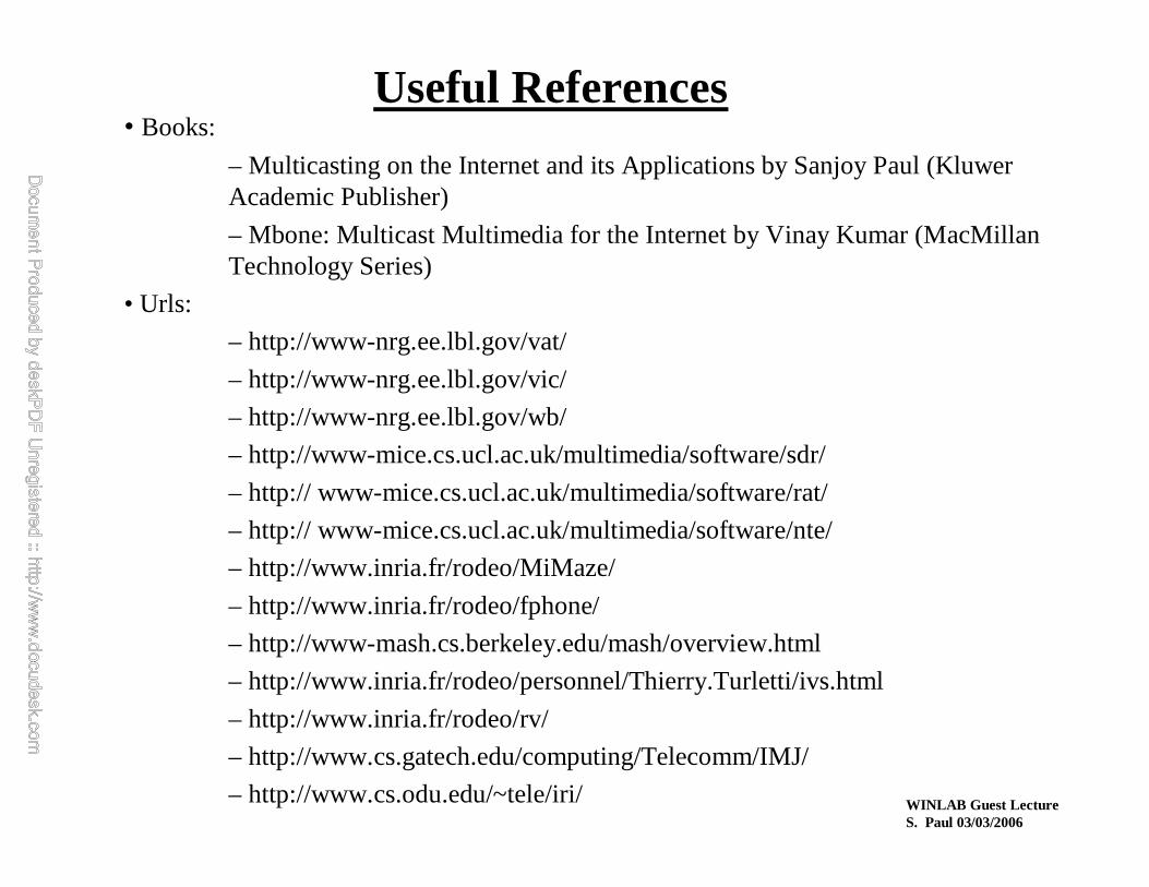
• Books:
– Multicasting on the Internet and its Applications by Sanjoy Paul (KluwerAcademic Publisher)
– Mbone: Multicast Multimedia for the Internet by Vinay Kumar (MacMillanTechnology Series)
• Urls:
– http://www-nrg.ee.lbl.gov/vat/
– http://www-nrg.ee.lbl.gov/vic/
– http://www-nrg.ee.lbl.gov/wb/
– http://www-mice.cs.ucl.ac.uk/multimedia/software/sdr/
– http:// www-mice.cs.ucl.ac.uk/multimedia/software/rat/
– http:// www-mice.cs.ucl.ac.uk/multimedia/software/nte/
– http://www.inria.fr/rodeo/MiMaze/
– http://www.inria.fr/rodeo/fphone/
– http://www-mash.cs.berkeley.edu/mash/overview.html
– http://www.inria.fr/rodeo/personnel/Thierry.Turletti/ivs.html
– http://www.inria.fr/rodeo/rv/
– http://www.cs.gatech.edu/computing/Telecomm/IMJ/
– http://www.cs.odu.edu/~tele/iri/
Useful References

WINLAB Guest LectureS. Paul 03/03/2006
Summary• IP Multicast -- best-effort multicast delivery• Multicast Backbone of the Internet (Mbone) - interim solution• Mbone tools have become default multimedia toolset for Internet• Multicast is still not widely deployed on the Internet
– Inter-domain multicast routing– Multicast address allocation– Management tool
• Reliable multicast is a key technology for a wide variety of applications on the Internet/intranets• Novel Applications
– Multi-party Games– Multi-media conferencing– Distance Learning– Wide-area “Push”
• New research– Flow/Congestion control
– Router-assisted reliable multicast– Naming

WINLAB Guest LectureS. Paul 03/03/2006
•Internet Group Management Protocol (IGMP)
— protocol between end-host and router
Extending IP Multicast beyond a Subnet -- IGMP
SENDERS
RECEIVERS
Sender’s IP 224.9.9.9 Multicast Data
Destination Address
IP Header
Router (1) IGMP query (Any Host interested in Any Group?)
(2) IGMP response (224.9.9.9)
Sender
Receiver
INTERNET
S2S1
S
(3) IGMP response (225.5.5.5)

WINLAB Guest LectureS. Paul 03/03/2006
• Host explicitly informs router when it leaves a multicast group
– reduces leave latency
IP Multicast -- IGMPv.2
SENDERS
RECEIVERS
Sender’s IP 224.9.9.9 Multicast Data
Destination Address
IP Header
Router (1) IGMP query (Any Host interested in Any Group?)(1) IGMP query (Any Host interested in Any Group?)
(2) IGMP response (224.9.9.9(2) IGMP response (224.9.9.9))
Sender
Receiver
INTERNET
S2S1
S
(3) IGMP leave (225.5.5.5)

WINLAB Guest LectureS. Paul 03/03/2006
• Receiver can specify which source(s) of a group it is (not) interested in
IP Multicast -- IGMPv.3
SENDERS
RECEIVERS
Sender’s IP 224.9.9.9 Multicast Data
Destination Address
IP Header
Router (1) IGMP query (Any Host interested in Any Group?)(1) IGMP query (Any Host interested in Any Group?)
(2) IGMP response (224.9.9.9, source=S2)
Sender
Receiver
INTERNET
S3S2
S
(3) IGMP response (225.5.5.5, source =/= S3)
S1

WINLAB Guest LectureS. Paul 03/03/2006
• Distance Vector Multicast Routing Protocol (DVMRP)
— Final multicast tree with grafted links
IP Multicast Routing- DVMRP
Sender
Receiver
Receiver
Receiver
Router
Sender
Receiver
SS
NEWRECEIVER
D
D
D
D
D
D
D
D
DD
D
D
Multicast Tree:
Data: D

WINLAB Guest LectureS. Paul 03/03/2006
• Distance Vector Multicast Routing Protocol (DVMRP)
— Flooding
IP Multicast Routing- DVMRP
Receiver Receiver
FF
F
F
F
FF
F F
F
F
F
F
F F
F F
FFF
FFF
F F F
F
F
Flooding:F
Router
Sender
Receiver
Sender
Receiver
SS

WINLAB Guest LectureS. Paul 03/03/2006
• Distance Vector Multicast Routing Protocol (DVMRP)
— Pruning
IP Multicast Routing- DVMRP
Sender
Receiver
Receiver
Receiver
P
PP
P P
P P
PP
PPRUNE Message: Multicast Tree:
PP
P
P
Router
Sender
Receiver
SS

WINLAB Guest LectureS. Paul 03/03/2006
• Distance Vector Multicast Routing Protocol (DVMRP)
— Final multicast tree
IP Multicast Routing- DVMRP
Sender
Receiver
Receiver
Receiver
Router
Sender
Receiver
SS
D
D
D
D
D
D
D D
D
D
Multicast Tree:
Data: D
WINLAB Guest LectureS. Paul 03/03/2006
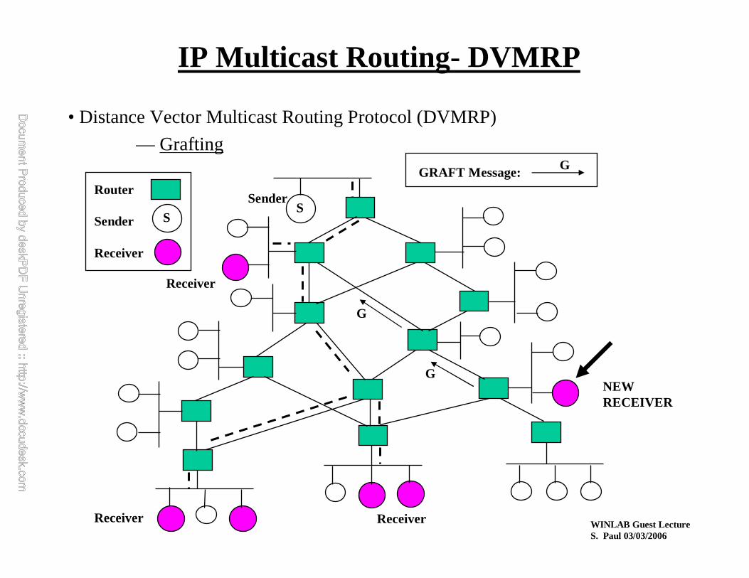
• Distance Vector Multicast Routing Protocol (DVMRP)
— Grafting
IP Multicast Routing- DVMRP
Sender
Receiver
Receiver
Receiver
GRAFT Message:
G
G
G
Router
Sender
Receiver
SS
NEWRECEIVER

WINLAB Guest LectureS. Paul 03/03/2006
• Protocol Independent Multicast (PIM)
— Rendezvous Point (RP)
IP Multicast Routing- PIM
Sender
Receiver
Receiver
Receiver
Join Message:
Receiver
RP
J
JJ
J
J
J
Reg(D)
IPTunnel
Register Message(containing Data):
Reg(D)
Router
Sender
Receiver
SS
WINLAB Guest LectureS. Paul 03/03/2006
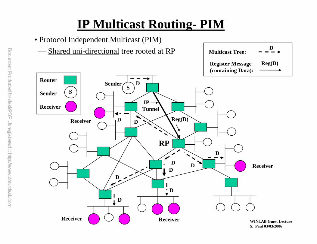
• Protocol Independent Multicast (PIM)
— Shared uni-directionaltree rooted at RP
IP Multicast Routing- PIM
Sender
Receiver
Receiver
Receiver
Multicast Tree:
Receiver
RP
D
DDD
D
D
Reg(D)
IPTunnel
Register Message(containing Data):
Reg(D)
Router
Sender
Receiver
SS
D
D
D
D
D

WINLAB Guest LectureS. Paul 03/03/2006
• Protocol Independent Multicast (PIM)
— Switches from shared tree to shortest path tree
IP Multicast Routing- PIM
Sender
Receiver
Receiver
Receiver
Multicast Tree:
Receiver
RP
D
D
D
D
Router
Sender
Receiver
SS
D
DD
D
D
D
D
D
D
WINLAB Guest LectureS. Paul 03/03/2006
MiscellaneousInter-Domain Solutions

WINLAB Guest LectureS. Paul 03/03/2006
Other Inter-Domain Choices
• Root Addressed Multicast Architecture (RAMA)– this was once known as “Simple Multicast”
– a special case of RAMA is “Express Multicast”
• Border Gateway Multicast Protocol (BGMP)– Not to be confused with MBGP

WINLAB Guest LectureS. Paul 03/03/2006
Root Addressed Multicast Architecture
• Uses “extended addressing”– Combines 4 byte source addr and 4 byte
destination addr
– Multicast address becomes (Core,Group) = (C,G)
• Solves limited-address problem
• Also solves address allocation problem
– (C,G) uniquely identifies group
• Use bi-directional shared trees

WINLAB Guest LectureS. Paul 03/03/2006
BGMP• Relies on multicast addresses being rooted in
some domain– Can use MASC or GLOP or ???
• Creates a single bi-directional tree across domains– Attempts to aggregate routing (if domains are allocated
address ranges)
– Different from PIM-SM is bi-directional trees
• BGMP is considered protocol of the future– Offers routing scalability not found in existing
protocols

WINLAB Guest LectureS. Paul 03/03/2006
• Border Gateway Multicast Protocol (BGMP)
— Inter-domain(as opposed to intra-domain) multicast routing protocol
IP Multicast Routing- BGMP
M-IGP BGMP BGMP M-IGP
M-IGP BGMP
BGMP M-IGP
BGMP M-IGP
BGMP M-IGP M-IGP BGMP
BGMP M-IGP M-IGP BGMPBGMP M-IGP M-IGP BGMP
Border Router
Border Router Border Router
Border Router
Border RouterBorder Router
Border Router
Border RouterBorder Router
Border Router Border Router
Domain-1
Domain-2
Domain-3
Domain-4
Domain-5
Domain-6Domain-8Domain-7
M-IGP: MulticastInterior Gateway Protocol
R2
R1
R3
R4
S2
S1
S
R
Sender:
Receiver:
WINLAB Guest LectureS. Paul 03/03/2006
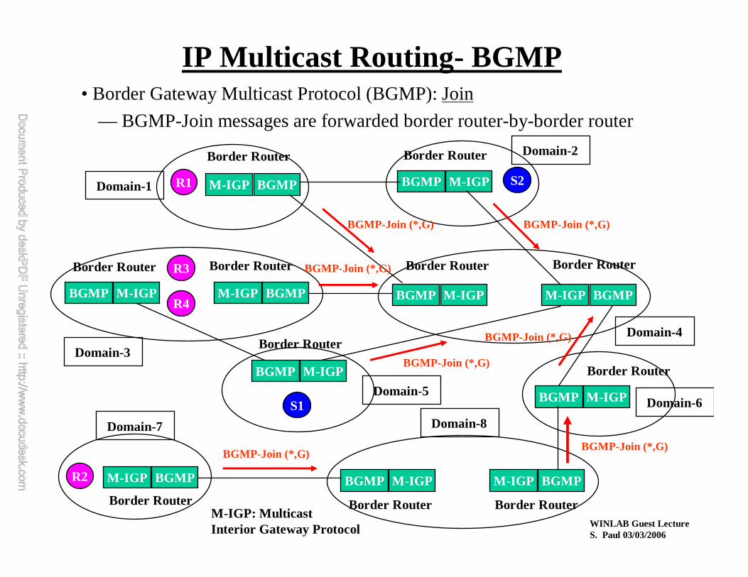
• Border Gateway Multicast Protocol (BGMP): Join
— BGMP-Join messages are forwarded border router-by-border router
IP Multicast Routing- BGMP
M-IGP BGMP BGMP M-IGP
M-IGP BGMP
BGMP M-IGP
BGMP M-IGP
BGMP M-IGP M-IGP BGMP
BGMP M-IGP M-IGP BGMPBGMP M-IGP M-IGP BGMP
Border Router
Border Router Border Router
Border Router
Border RouterBorder Router
Border Router
Border RouterBorder Router
Border Router Border Router
Domain-1
Domain-2
Domain-3
Domain-4
Domain-5Domain-6
Domain-8Domain-7
M-IGP: MulticastInterior Gateway Protocol
R2
R1
R3
R4
S2
S1
BGMP-Join (*,G)
BGMP-Join (*,G)
BGMP-Join (*,G)
BGMP-Join (*,G) BGMP-Join (*,G)
BGMP-Join (*,G)
BGMP-Join (*,G)
WINLAB Guest LectureS. Paul 03/03/2006
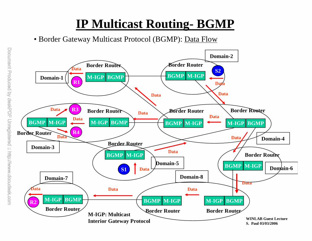
• Border Gateway Multicast Protocol (BGMP): Data Flow
IP Multicast Routing- BGMP
M-IGP BGMP BGMP M-IGP
M-IGP BGMP
BGMP M-IGP
BGMP M-IGP
BGMP M-IGP M-IGP BGMP
BGMP M-IGP M-IGP BGMPBGMP M-IGP M-IGP BGMP
Border Router
Border Router Border Router
Border Router
Border RouterBorder Router
Border Router
Border Router
Border Router
Border Router Border Router
Domain-1
Domain-2
Domain-3
Domain-4
Domain-5Domain-6
Domain-8Domain-7
M-IGP: MulticastInterior Gateway Protocol
R2
R1
R3
R4
S2
S1
Data
Data
Data
Data
DataData Data
Data
Data
Data
Data
Data
Data
Data
Data
Data

WINLAB Guest LectureS. Paul 03/03/2006
• Client uses MDHCP to request a multicast address from a local MAAS
• MAAS servers use AAP to claim multicast addresses and inform peer MAAS
• MASC allocates multicast address sets to domains
Multicast Address Allocation
MAAS MAAS
MAASMDHCP MDHCP
MULTICASTAAP
MASC Router
MASC Router
TCP MASC Exchanges
AllocationDomain
AllocationDomain
MDHCP: Multicast Dynamic Host Configuration ProtocolMAAS: Multicast Address Allocation ServerMASC: Multicast Address Set Claim; AAP: Address Allocation Protocol

WINLAB Guest LectureS. Paul 03/03/2006
Multicast Address Allocation (cont’d)
ClientLocalMAASServer
RemoteMAASServer
MASCnode fordomain
MDHCP scope req
MDHCP scope rep
MDHCP addr req AAP address claim
AAP address collide (a rare event)
AAP address claimAfter AAP timeout(e.g., 2 sec)
MDHCP addr allocAAP address set near exhaustion warning
AAP address set advertisement
Periodic AAPaddress claim
AAP address set advertisement
After MASC claiminterval (e.g., 1 day)

WINLAB Guest LectureS. Paul 03/03/2006
Multicast Security
• Based on internet draft by Canetti, Cheng et.al.• Security Requirements for Multicast Communication
– Group membership control and confidentiality¬ group communication accessible onlyto group members
– Group data authentication¬ ability to verify that the group communication was generated from a sourcewithin the group
– Individual source authentication¬ ability to verify the identity of the sourceof data
• Design characteristics:– must be independent of underlying routing mechanisms– mimic IPSec architecture as much as possible– use existing components wherever possible– minimize operating system kernel modification
WINLAB Guest LectureS. Paul 03/03/2006
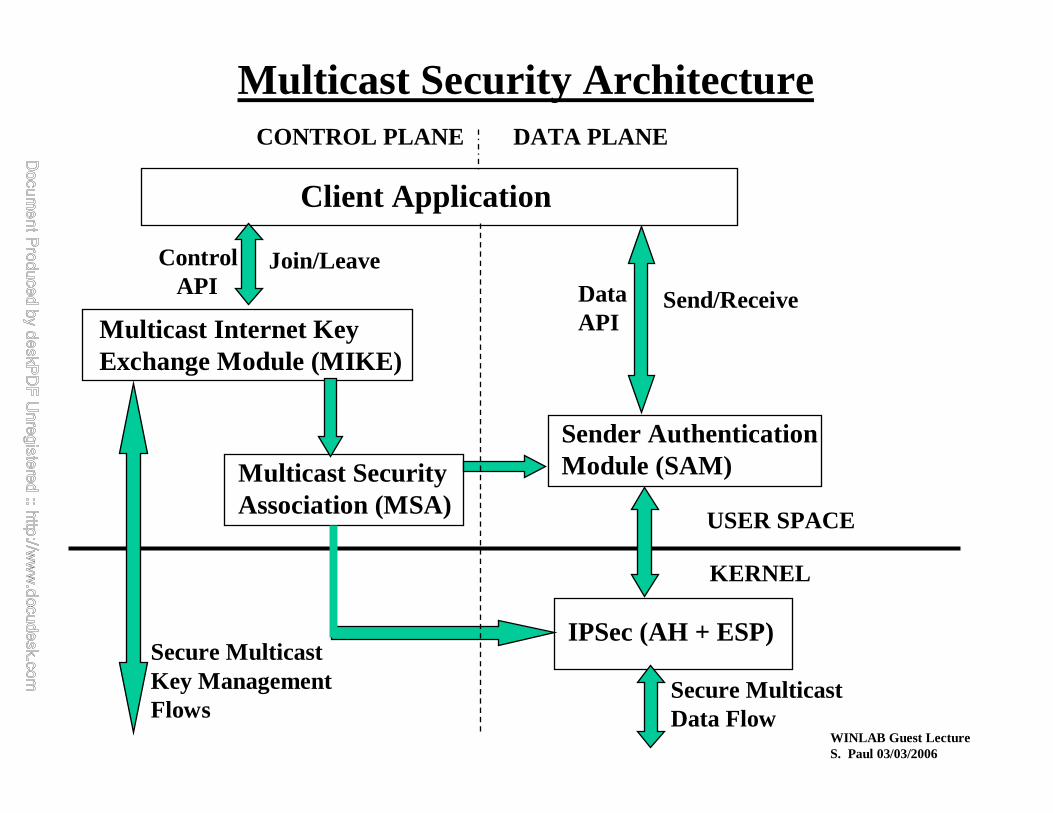
Multicast Security Architecture
Client Application
Multicast Internet Key Exchange Module (MIKE)
Multicast Security Association (MSA)
Sender Authentication Module (SAM)
IPSec (AH + ESP)Secure MulticastKey Management Flows
Secure MulticastData Flow
USER SPACE
KERNEL
Send/ReceiveData API
Control API
Join/Leave
CONTROL PLANE DATA PLANE

WINLAB Guest LectureS. Paul 03/03/2006
Multicast Security Message Exchange
Client Application
Multicast Internet Key Exchange Module (MIKE)
Multicast Security Association (MSA) Sender Authentication
Module (SAM)
IPSec (AH + ESP)Secure MulticastKey Management Flows
Secure MulticastData Flow
USER SPACE
KERNEL
Send/Receive
Data API
Control API Join/Leave
CONTROL PLANE DATA PLANE• Control Flow:— Client join (group, auth):
– MIKE registers client with group controller(s), sets up MSA, enables AH/ESP, SAM
— Key update:– internal MIKE messages– separately auth and encr
— Client Leave:– MIKE de-registers client with group controllers, deletes MSA
• Data Flow:— Sending of data:
– if no src auth, data sent directly using UDP– if src auth, data first sent to SAM and then to AH/ESP
— Receipt of data:– first processed by AH/ESP– decryption and group auth– src auth by SAM

WINLAB Guest LectureS. Paul 03/03/2006
• Books:
– Multicasting on the Internet and its Applications by Sanjoy Paul (Kluwer Academic Publisher)
– Deploying Ip Multicast in the Enterprise by Thomas Maufer(Prentice Hall)
– Mbone: Multicast Multimedia for the Internet by Vinay Kumar (MacMillan Technology Series)
• Urls:
– http://netweb.usc.edu/multicast/multicast_routing.html
– http://netweb.usc.edu/multicast/pim/
– http://netweb.usc.edu/multicast/bgmp/
– ftp://src.doc.ic.ac.uk/rfc/rfc1075.txt
– http://antc.uoregon.edu/MBONED/
– http://www.mbone.com/
– http://www.aciri.org/malloc/
Useful References


