Compatibility Report
Comtrol IO-Link Master
ASCO Numatics 580 IO-Link Valve Manifold Device
4/20/2017 ASCO Numatics 580 IO-Link Valve Manifold Device 2
Table of Contents
Table of Contents .................................................................................................................................................................... 2
Test Report Overview ............................................................................................................................................................. 3
IO-Link Master – IO-Link Diagnostics Page ............................................................................................................................ 3
Configuring IO-Link Settings Settings ..................................................................................................................................... 4
After Configuring Friendly Port Names ................................................................................................................................ 5
Setting Up Passwords ............................................................................................................................................................. 6
IO-Link Device Configuration .................................................................................................................................................. 7
Loading the IODD Files ....................................................................................................................................................... 7
Verifying that the Correct IODD Files Loaded ................................................................................................................... 10
Changing Valve Manifold Parameters Using the GUI ....................................................................................................... 11
Changing Parameters Using the ISDU Interface............................................................................................................... 14
Using the Automatic Data Storage Feature .......................................................................................................................... 17
Clearing Data Storage ........................................................................................................................................................... 21
Using the Manual Data Storage UPLOAD Feature............................................................................................................... 23
Resetting the Valve Manifold to Factory Defaults ................................................................................................................. 25
Using the Manual Data Storage DOWNLOAD Feature ........................................................................................................ 27
Using the Device Validation Feature ..................................................................................................................................... 29
Incompatible Device Attached to Port ............................................................................................................................... 29
Using the Data Validation Feature ........................................................................................................................................ 31
4/20/2017 ASCO Numatics 580 IO-Link Valve Manifold Device 3
Test Report Overview
The ASCO Numatics 580 IO-Link Valve Manifold Device operates properly with the Comtrol IO-Link Master. This report contains the following topics:
• IO-Link Master – IO-Link Diagnostics page
• Configuring IO-Link settings
• Setting up passwords
• IO-Link device configuration
• Using the data storage feature
• Using the device validation feature
The Valve Manifold was tested using Application Base v1.4.20 on the IO-Link Master 4-EIP (4-port machine mountable IP67). This report does not illustrate all Comtrol IO-Link Master features, such as: EtherNet/IP and Modbus/TCP configuration, uploading the latest software, or network configuration.
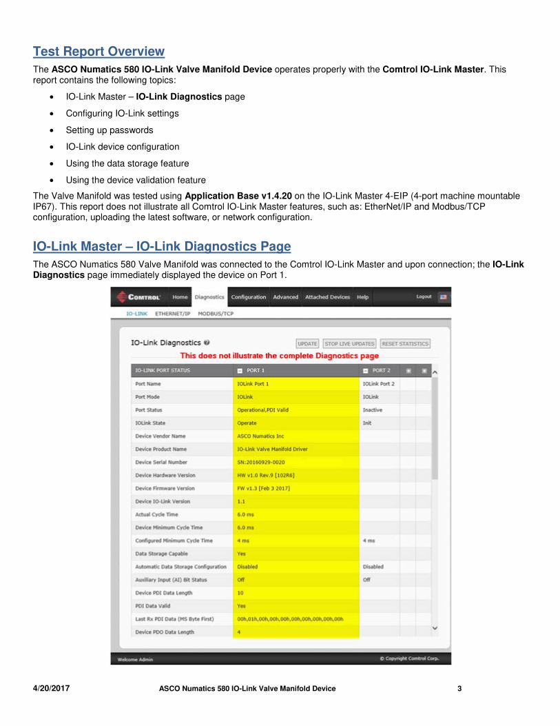
IO-Link Master – IO-Link Diagnostics Page
The ASCO Numatics 580 Valve Manifold was connected to the Comtrol IO-Link Master and upon connection; the IO-Link Diagnostics page immediately displayed the device on Port 1.
4/20/2017 ASCO Numatics 580 IO-Link Valve Manifold Device 4
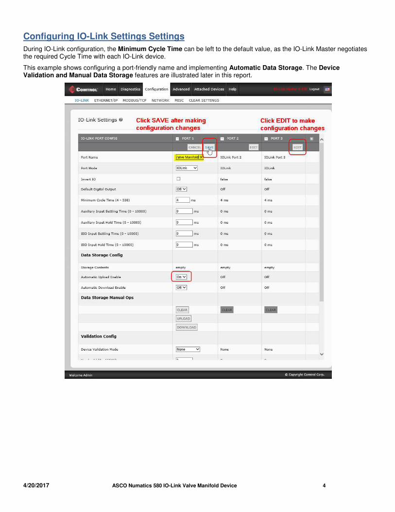
Configuring IO-Link Settings Settings
During IO-Link configuration, the Minimum Cycle Time can be left to the default value, as the IO-Link Master negotiates the required Cycle Time with each IO-Link device.
This example shows configuring a port-friendly name and implementing Automatic Data Storage. The Device Validation and Manual Data Storage features are illustrated later in this report.
4/20/2017 ASCO Numatics 580 IO-Link Valve Manifold Device 5
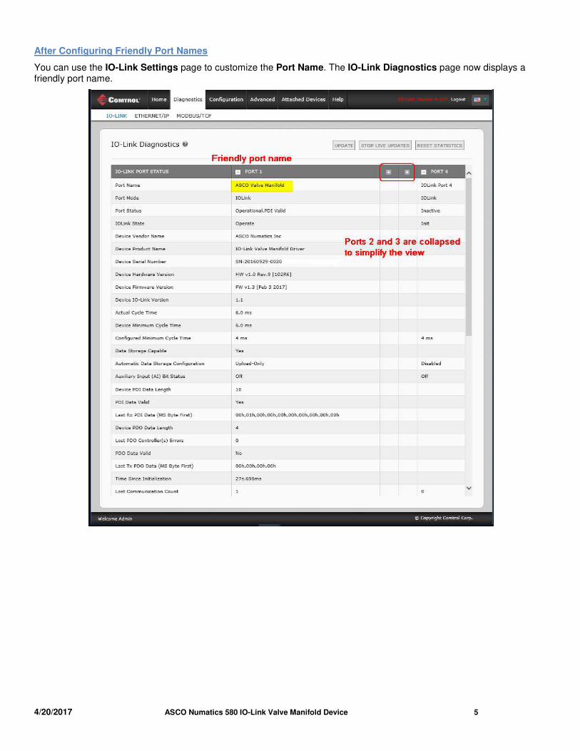
After Configuring Friendly Port Names
You can use the IO-Link Settings page to customize the Port Name. The IO-Link Diagnostics page now displays a friendly port name.
4/20/2017 ASCO Numatics 580 IO-Link Valve Manifold Device 6
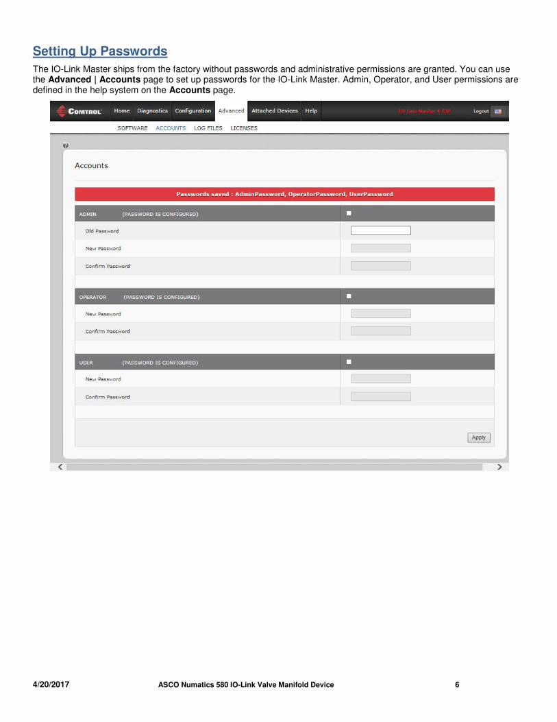
Setting Up Passwords
The IO-Link Master ships from the factory without passwords and administrative permissions are granted. You can use the Advanced | Accounts page to set up passwords for the IO-Link Master. Admin, Operator, and User permissions are defined in the help system on the Accounts page.
4/20/2017 ASCO Numatics 580 IO-Link Valve Manifold Device 7
IO-Link Device Configuration
You can use the Comtrol IO-Link Master to configure the IO-Link device.
• If an IODD file is loaded, you may want to use the table (GUI) on the top of the IO-Link Device – Port page to change parameter settings.
• If an IODD file is not loaded, you can use the ISDU Interface on the bottom of the IO-Link Device – Port page
This section discusses the following topics:
• Loading IODD files and verifying that the correct IODD file is loaded
• Changing IO-Link device parameters using the GUI
• Resetting to the IO-Link device to factory defaults
• Changing IO-Link device parameters using the ISDU Interface
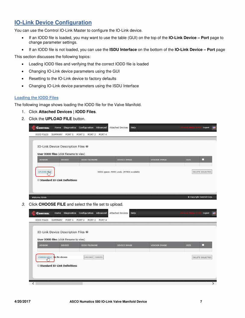
Loading the IODD Files
The following image shows loading the IODD file for the Valve Manifold.
1. Click Attached Devices | IODD Files.
2. Click the UPLOAD FILE button.
3. Click CHOOSE FILE and select the file set to upload.

4/20/2017 ASCO Numatics 580 IO-Link Valve Manifold Device 8
4. Click the UPLOAD button.
5. If there are files in the IODD file set that are not required by the associated xml file, the IO-Link Master does not load the files, and displays an Ignored Files message. Click Ok to close the message.
6. Click the file name in the table if you want to review the xml file.
4/20/2017 ASCO Numatics 580 IO-Link Valve Manifold Device 9
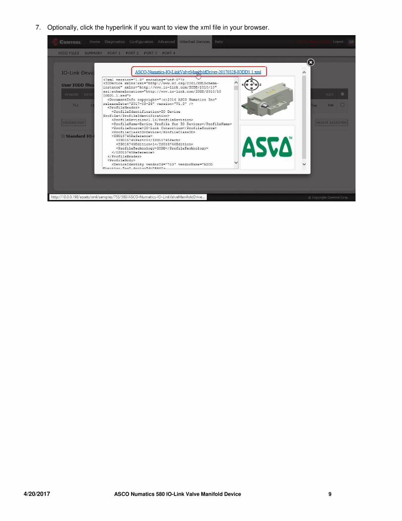
7. Optionally, click the hyperlink if you want to view the xml file in your browser.
4/20/2017 ASCO Numatics 580 IO-Link Valve Manifold Device 10
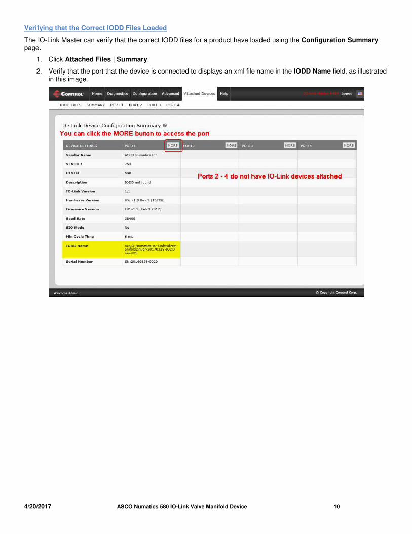
Verifying that the Correct IODD Files Loaded
The IO-Link Master can verify that the correct IODD files for a product have loaded using the Configuration Summary page.
1. Click Attached Files | Summary.
2. Verify that the port that the device is connected to displays an xml file name in the IODD Name field, as illustrated in this image.
4/20/2017 ASCO Numatics 580 IO-Link Valve Manifold Device 11
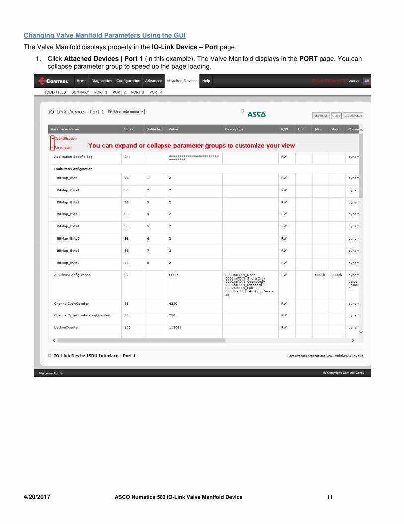
Changing Valve Manifold Parameters Using the GUI
The Valve Manifold displays properly in the IO-Link Device – Port page:
1. Click Attached Devices | Port 1 (in this example). The Valve Manifold displays in the PORT page. You can collapse parameter group to speed up the page loading.
4/20/2017 ASCO Numatics 580 IO-Link Valve Manifold Device 12
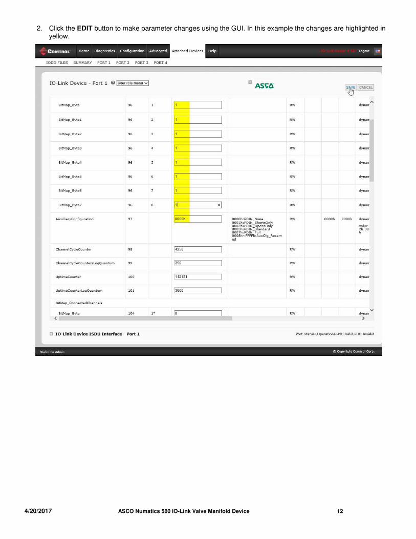
2. Click the EDIT button to make parameter changes using the GUI. In this example the changes are highlighted in yellow.
4/20/2017 ASCO Numatics 580 IO-Link Valve Manifold Device 13
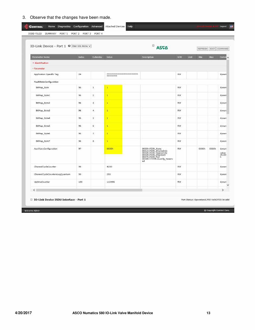
3. Observe that the changes have been made.
4/20/2017 ASCO Numatics 580 IO-Link Valve Manifold Device 14
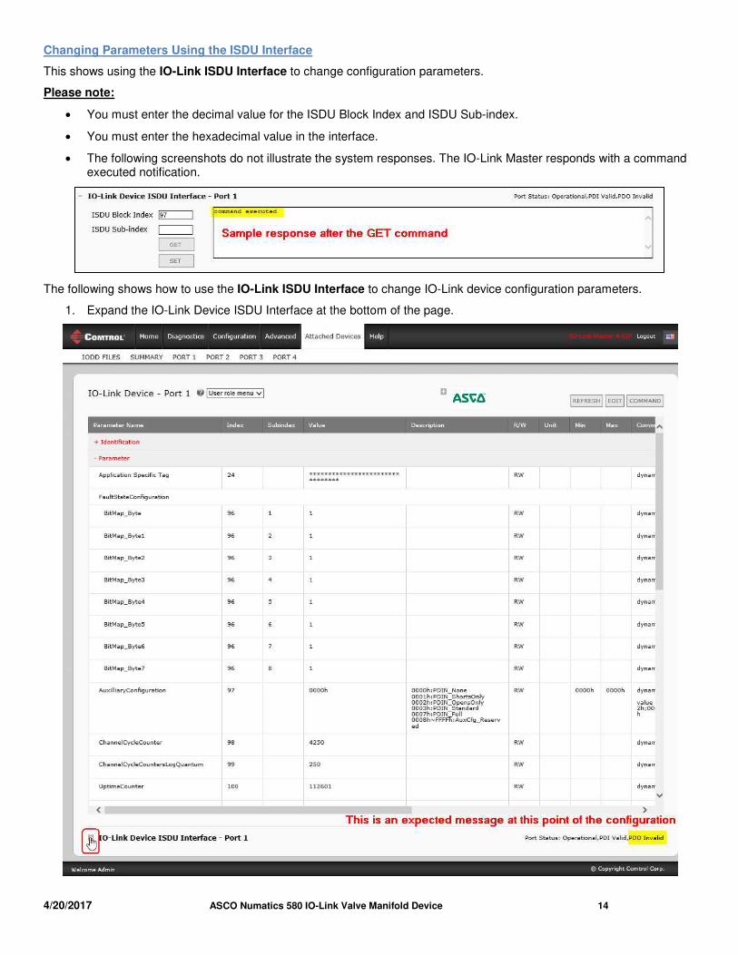
Changing Parameters Using the ISDU Interface
This shows using the IO-Link ISDU Interface to change configuration parameters.
Please note:
• You must enter the decimal value for the ISDU Block Index and ISDU Sub-index.
• You must enter the hexadecimal value in the interface.
• The following screenshots do not illustrate the system responses. The IO-Link Master responds with a command executed notification.
The following shows how to use the IO-Link ISDU Interface to change IO-Link device configuration parameters.
1. Expand the IO-Link Device ISDU Interface at the bottom of the page.
4/20/2017 ASCO Numatics 580 IO-Link Valve Manifold Device 15
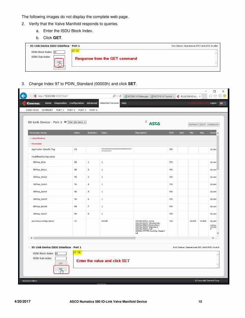
The following images do not display the complete web page.
2. Verify that the Valve Manifold responds to queries.
a. Enter the ISDU Block Index.
b. Click GET.
3. Change Index 97 to PDIN_Standard (00003h) and click SET.
4/20/2017 ASCO Numatics 580 IO-Link Valve Manifold Device 16
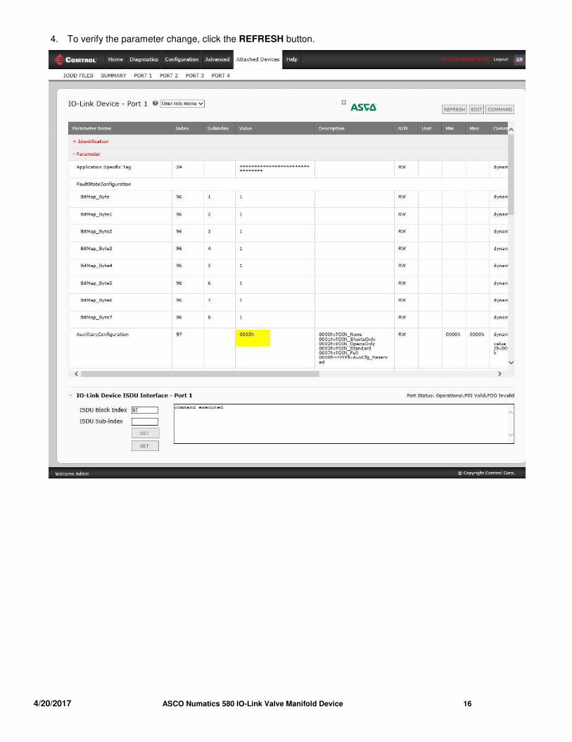
4. To verify the parameter change, click the REFRESH button.
4/20/2017 ASCO Numatics 580 IO-Link Valve Manifold Device 17
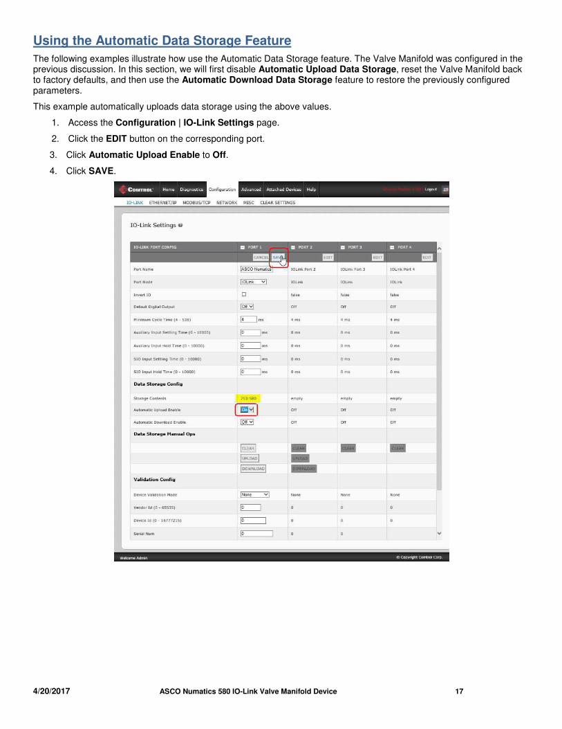
Using the Automatic Data Storage Feature
The following examples illustrate how use the Automatic Data Storage feature. The Valve Manifold was configured in the previous discussion. In this section, we will first disable Automatic Upload Data Storage, reset the Valve Manifold back to factory defaults, and then use the Automatic Download Data Storage feature to restore the previously configured parameters.
This example automatically uploads data storage using the above values.
1. Access the Configuration | IO-Link Settings page.
2. Click the EDIT button on the corresponding port.
3. Click Automatic Upload Enable to Off.
4. Click SAVE.
4/20/2017 ASCO Numatics 580 IO-Link Valve Manifold Device 18
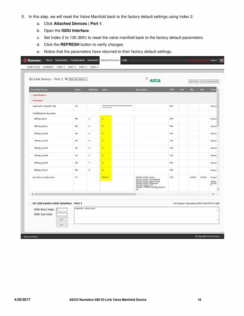
5. In this step, we will reset the Valve Manifold back to the factory default settings using Index 2.
a. Click Attached Devices | Port 1.
b. Open the ISDU Interface.
c. Set Index 2 to 130 (82h) to reset the valve manifold back to the factory default parameters.
d. Click the REFRESH button to verify changes.
e. Notice that the parameters have returned to their factory default settings.
4/20/2017 ASCO Numatics 580 IO-Link Valve Manifold Device 19
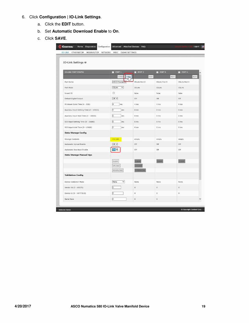
6. Click Configuration | IO-Link Settings.
a. Click the EDIT button.
b. Set Automatic Download Enable to On.
c. Click SAVE.
4/20/2017 ASCO Numatics 580 IO-Link Valve Manifold Device 20
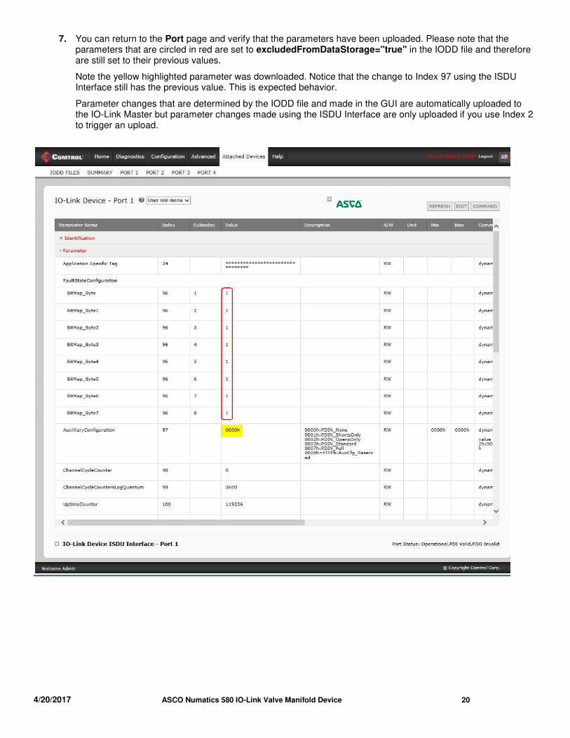
7. You can return to the Port page and verify that the parameters have been uploaded. Please note that the parameters that are circled in red are set to excludedFromDataStorage="true" in the IODD file and therefore are still set to their previous values.
Note the yellow highlighted parameter was downloaded. Notice that the change to Index 97 using the ISDU Interface still has the previous value. This is expected behavior.
Parameter changes that are determined by the IODD file and made in the GUI are automatically uploaded to the IO-Link Master but parameter changes made using the ISDU Interface are only uploaded if you use Index 2 to trigger an upload.
4/20/2017 ASCO Numatics 580 IO-Link Valve Manifold Device 21
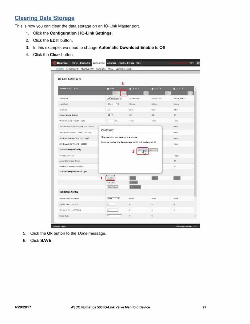
Clearing Data Storage
This is how you can clear the data storage on an IO-Link Master port.
1. Click the Configuration | IO-Link Settings.
2. Click the EDIT button.
3. In this example, we need to change Automatic Download Enable to Off.
4. Click the Clear button.
5. Click the Ok button to the Done message.
6. Click SAVE.
4/20/2017 ASCO Numatics 580 IO-Link Valve Manifold Device 22
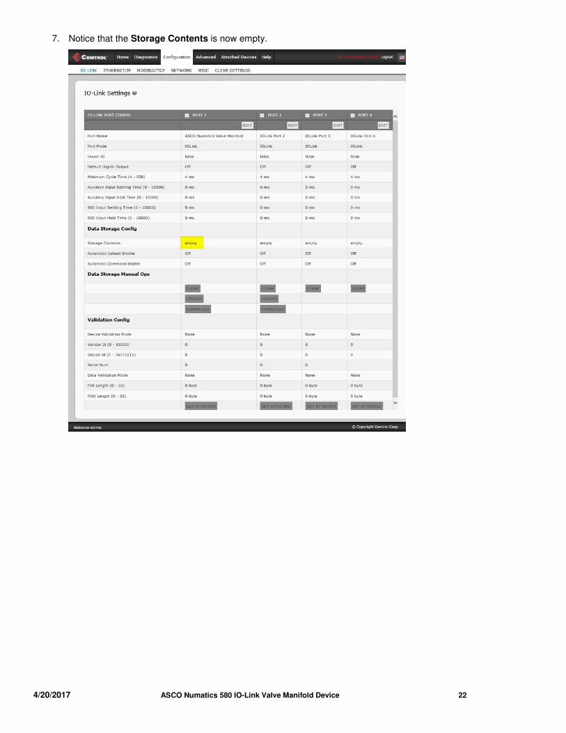
7. Notice that the Storage Contents is now empty.
4/20/2017 ASCO Numatics 580 IO-Link Valve Manifold Device 23
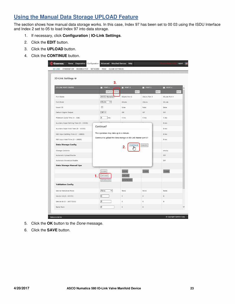
Using the Manual Data Storage UPLOAD Feature
The section shows how manual data storage works. In this case, Index 97 has been set to 00 03 using the ISDU Interface and Index 2 set to 05 to load Index 97 into data storage.
1. If necessary, click Configuration | IO-Link Settings.
2. Click the EDIT button.
3. Click the UPLOAD button.
4. Click the CONTINUE button.
5. Click the OK button to the Done message.
6. Click the SAVE button.
4/20/2017 ASCO Numatics 580 IO-Link Valve Manifold Device 24
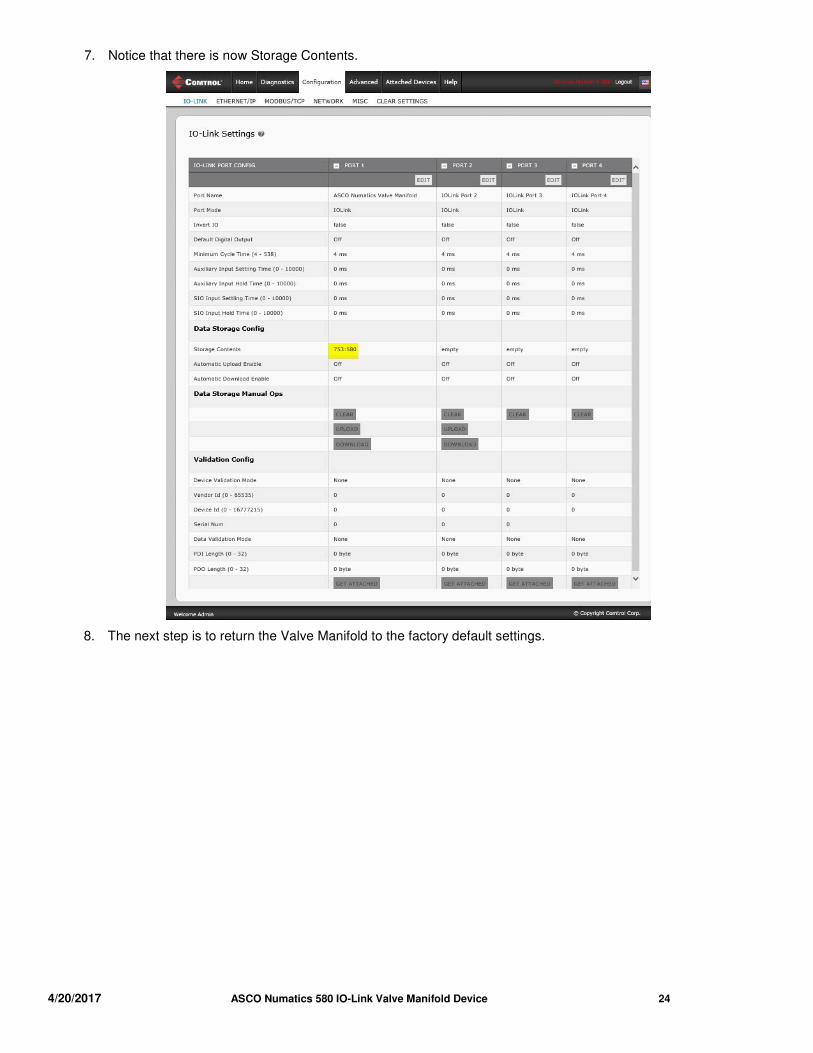
7. Notice that there is now Storage Contents.
8. The next step is to return the Valve Manifold to the factory default settings.
4/20/2017 ASCO Numatics 580 IO-Link Valve Manifold Device 25
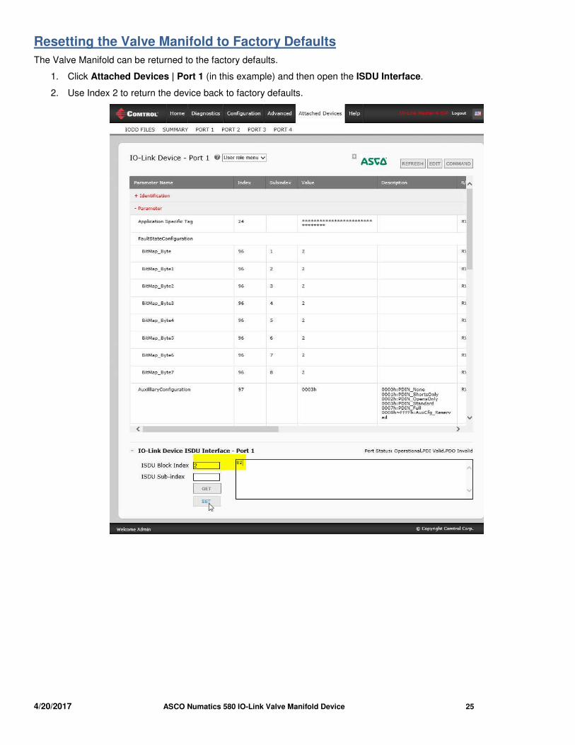
Resetting the Valve Manifold to Factory Defaults
The Valve Manifold can be returned to the factory defaults.
1. Click Attached Devices | Port 1 (in this example) and then open the ISDU Interface.
2. Use Index 2 to return the device back to factory defaults.
4/20/2017 ASCO Numatics 580 IO-Link Valve Manifold Device 26
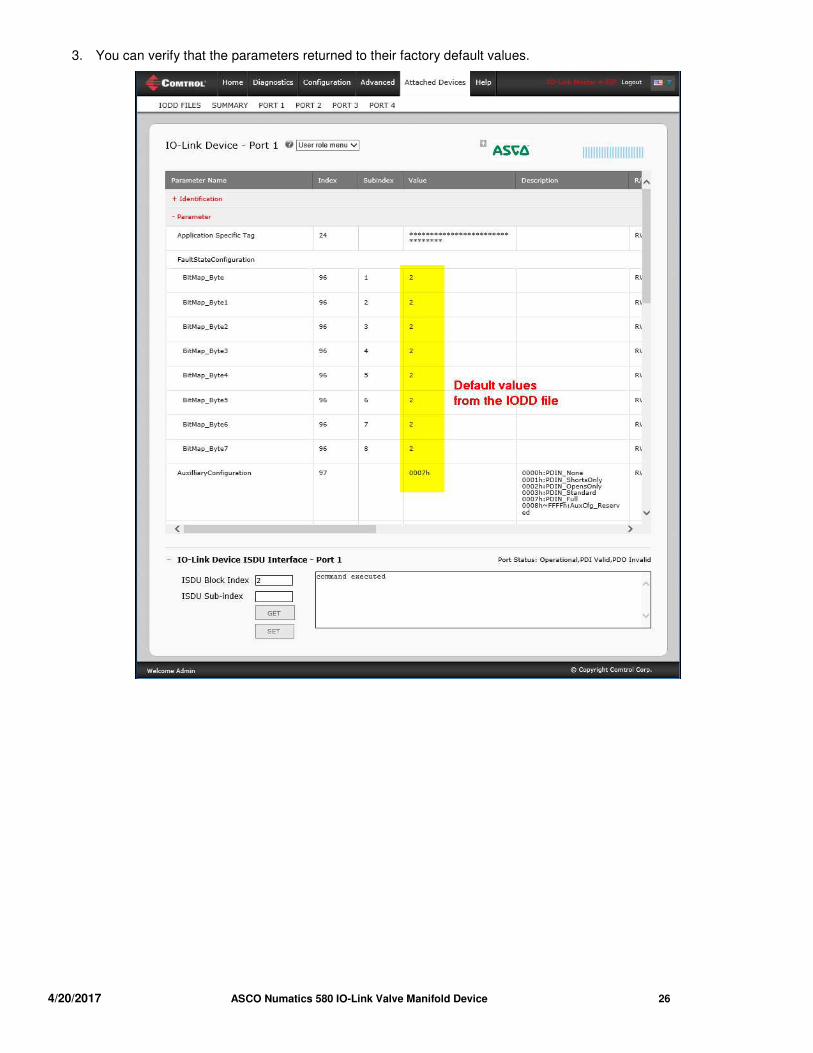
3. You can verify that the parameters returned to their factory default values.
4/20/2017 ASCO Numatics 580 IO-Link Valve Manifold Device 27
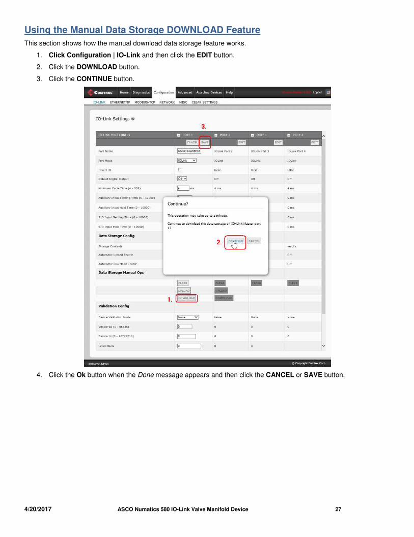
Using the Manual Data Storage DOWNLOAD Feature
This section shows how the manual download data storage feature works.
1. Click Configuration | IO-Link and then click the EDIT button.
2. Click the DOWNLOAD button.
3. Click the CONTINUE button.
4. Click the Ok button when the Done message appears and then click the CANCEL or SAVE button.
4/20/2017 ASCO Numatics 580 IO-Link Valve Manifold Device 28
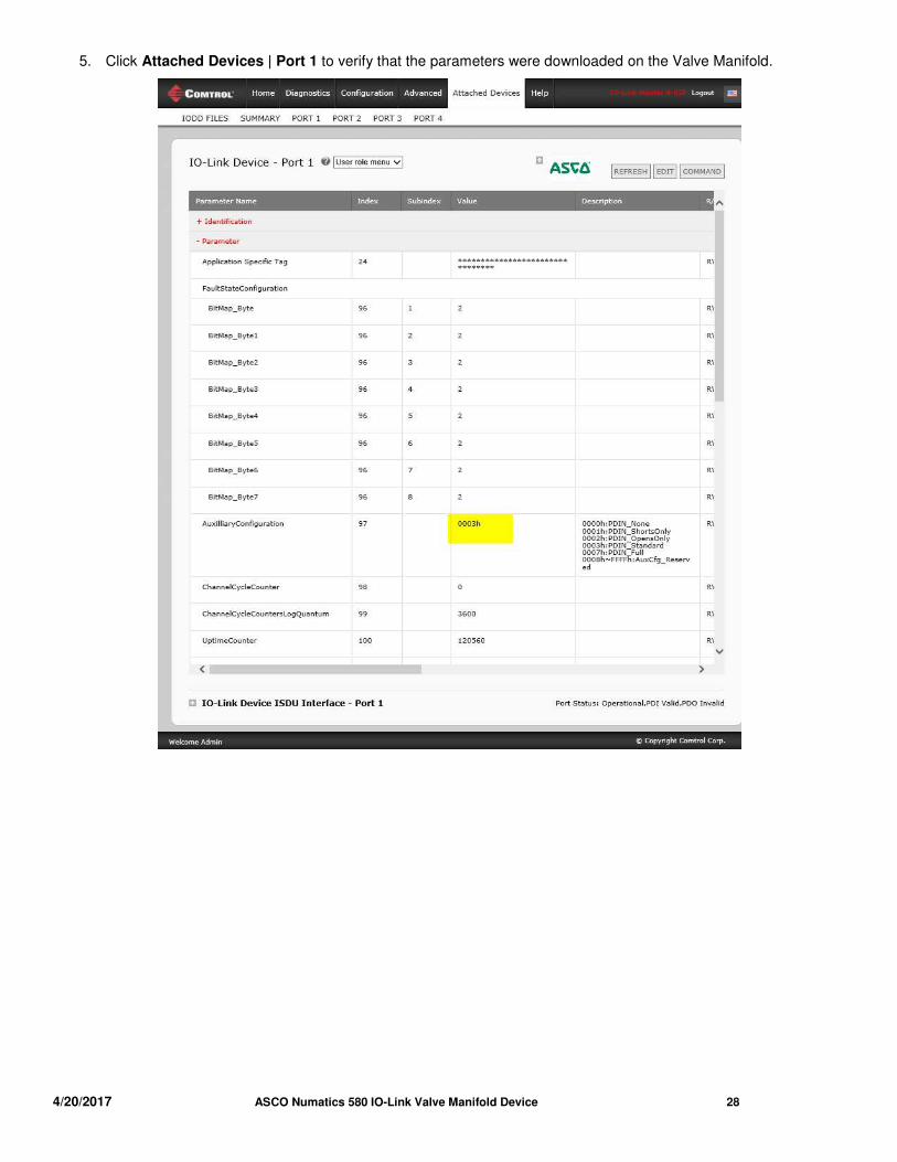
5. Click Attached Devices | Port 1 to verify that the parameters were downloaded on the Valve Manifold.
4/20/2017 ASCO Numatics 580 IO-Link Valve Manifold Device 29
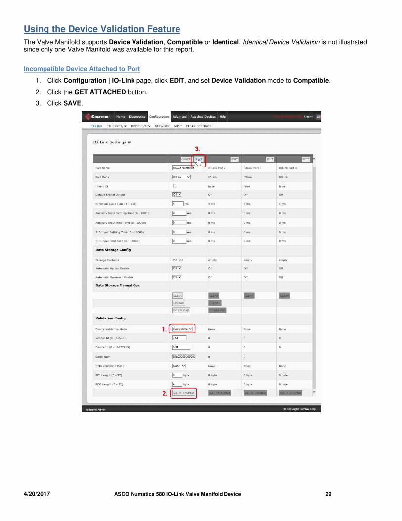
Using the Device Validation Feature
The Valve Manifold supports Device Validation, Compatible or Identical. Identical Device Validation is not illustrated since only one Valve Manifold was available for this report.
Incompatible Device Attached to Port
1. Click Configuration | IO-Link page, click EDIT, and set Device Validation mode to Compatible.
2. Click the GET ATTACHED button.
3. Click SAVE.
4/20/2017 ASCO Numatics 580 IO-Link Valve Manifold Device 30
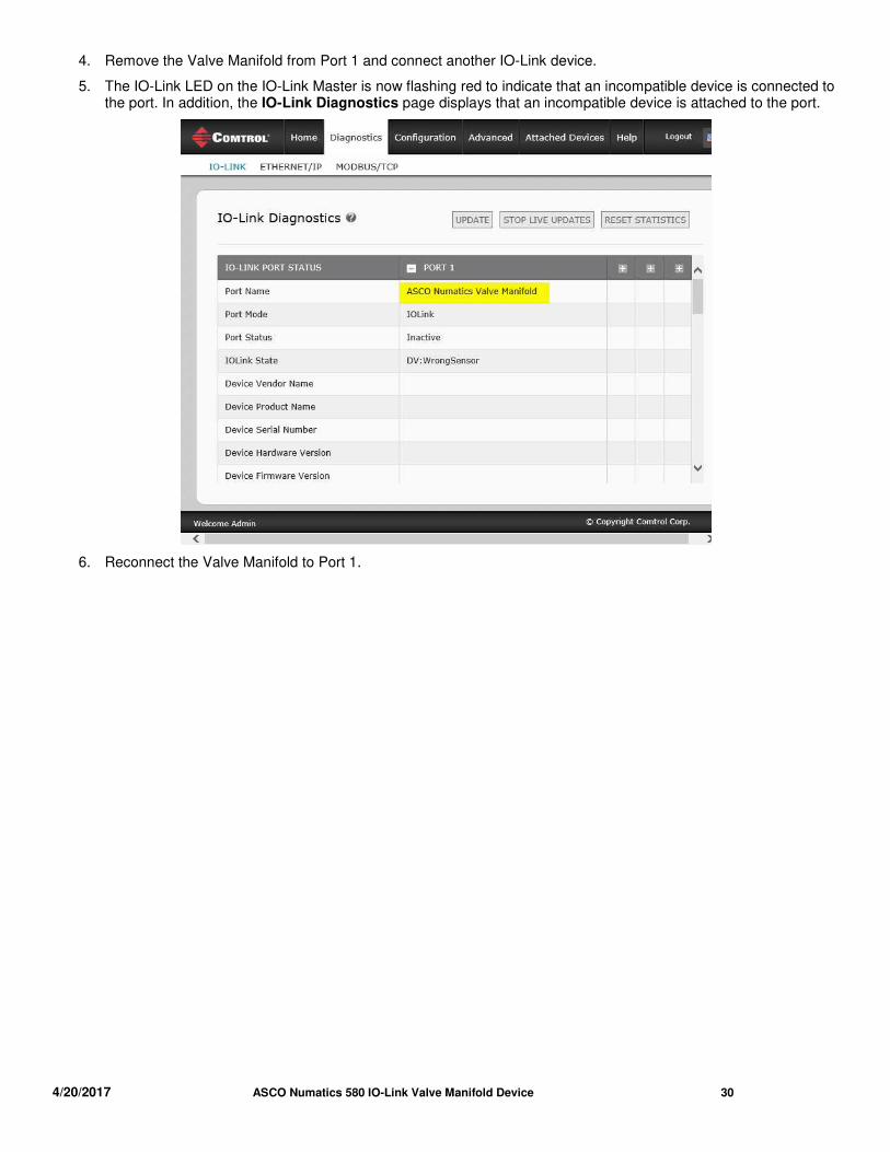
4. Remove the Valve Manifold from Port 1 and connect another IO-Link device.
5. The IO-Link LED on the IO-Link Master is now flashing red to indicate that an incompatible device is connected to the port. In addition, the IO-Link Diagnostics page displays that an incompatible device is attached to the port.
6. Reconnect the Valve Manifold to Port 1.
4/20/2017 ASCO Numatics 580 IO-Link Valve Manifold Device 31
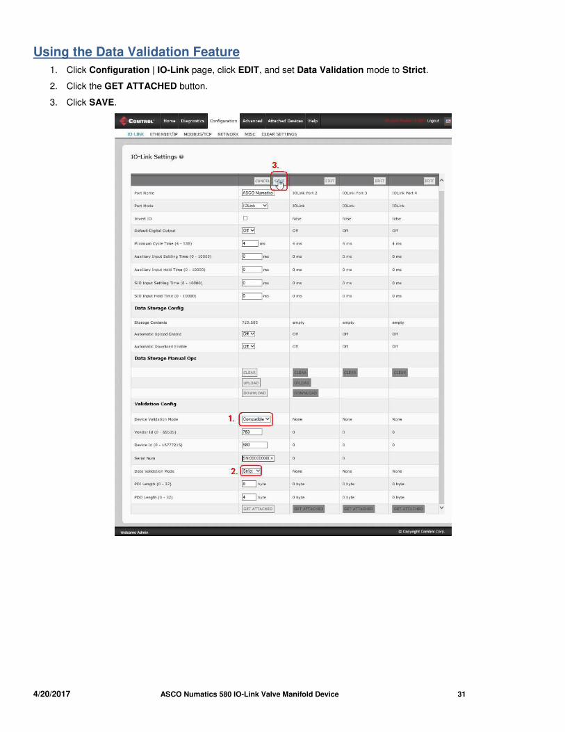
Using the Data Validation Feature
1. Click Configuration | IO-Link page, click EDIT, and set Data Validation mode to Strict.
2. Click the GET ATTACHED button.
3. Click SAVE.


