
79
Courtesy : Tata Johnson Controls Automotive Limited, India
4.1 Why do We Carry Out Meshing?
No. of Points = ∞DOF per Point = 6
Total equations = ∞
No. of Nodes = 8
DOF per Node = 6
Total equations = 48
The basic idea of FEA is to make calculations at only limited (Finite) number of points and then
interpolate the results for the entire domain (surface or volume). Any continuous object has in"nite
degrees of freedom and it’s just not possible to solve the problem in this format. Finite Element
Method reduces the degrees of freedom from in"nite to "nite with the help of discretization or
meshing (nodes and elements).
IV Introduction to Meshing
This chapter includes material from the book “Practical Finite Element Analysis”. It also has been
reviewed and has additional material added by Gareth Lee.

80
4.2 Types of Elements
Elements
1-D 2-D 3-D Other
yx
z
x >>> y, z
Midsurface
t - thickness of plate
t
t/2
x , z >>> y x ~ y ~ z
One of the dimensions is
very large in comparison to
the other two
Element shape – line
Additional data from user -
remaining two dimensions
i.e. area of cross section
Element type – rod, bar,
beam, pipe, axisymmetric
shell, etc
Practical applications -
Long shafts, beams, pin
joint, connection elements,
etc.
Two of the dimensions are
very large in comparison
to the third one
Element shape – quad, tria
Additional data from user
- remaining dimension i.e.
thickness
Element type – thin shell,
plate, membrane, plane
stress, plane strain, ,
axisymmetric solid, etc.
Practical applications
- Sheet metal parts,
plastic components like an
instrument panel ,etc.
All dimensions are
comparable
Element shape – tetra,
penta, hex, pyramid
Additional data from
user – none
Element type – solid
Practical applications
- Transmission casing,
engine block, crankshaft,
etc.
Mass – Point element,
concentrated mass at the
center of gravity of the
component
Spring – translational and
rotational sti#ness
Damper - damping
coe$cient
Gap – Gap distance,
sti#ness, friction
Rigid – RBE2, RBE3
Weld
4.3 How to Decide the Element Type
Element type selection
Geometry size and shape Type of analysis Time allotted for
project
a. Geometry size and shape
For an analysis, the software needs all three dimensions de"ned. It can not make calculations unless
the geometry is de"ned completely (by meshing using nodes and elements).
The geometry can be categorized as 1-D, 2-D, or 3-D based on the dominant dimensions and then
they type of element is selected accordingly.
1-D element: Used for geometries having one of the dimensions that is very large in comparison to
the other two.

81
Y
X
Z
10
5
1000
x>>> y, z
1000>>> 5, 10
The shape of the 1-D element is a line. When the element is created by connecting two nodes, the
software knows about only one out of the 3 dimensions. The remaining two dimensions, the area of
the cross section, must be de"ned by the user as additional input data and assigned to the respective
elements
Practical Example: Long shaft, rod, beam, column, spot welding, bolted joints, pin joints, bearing
modeling, etc.
2-D Element: Used when two of the dimensions are very large in comparison to the third one.
500
300
2
500, 300 >> 10 mm
x, z >>> y
Y
X
Z
2-D meshing is carried out on a mid surface of the part. 2-D elements are planar, just like paper. By
creating 2-D elements, the software knows 2 out of the 3 required dimensions. The third dimension,
thickness, has to provided by the user as an additional input data.
Why is 2-D meshing carried out on a mid surface?
Mathematically, the element thickness speci"ed by the user is assigned half on the element top and
half on the bottom side. Hence, in order to represent the geometry appropriately, it is necessary to
extract the mid surface and then mesh on the mid surface. Midsurface
t - thickness of plate
t
t/2
Practical Examples: All sheet metal parts, plastic components like instrument panels, etc. In general,
2-D meshing is used for parts having a width / thickness ratio > 20.

82
Limitations of mid surface and 2-D meshing –
2-D meshing would lead to a higher approximation if used for
- variable part thickness
- surfaces are not planner and have di#erent features on two sides.
3-D Element : used when all the three dimension are comparable
20050
100
x ~ y ~ z
100 ~ 200 ~ 50
Y
X
Z
Practical Examples : Transmission casing, clutch housing, engine block, connecting rod, crank shaft etc.
Tractor Components Mesh ( Image Source : Altair Calendar 2005
Courtesy : Mahindra and Mahindra Ltd., Tractor Division)
b. Based on the type of analysis :
Structural and fatigue analysis - Quad, hex elements are preferred over trias, tetras and pentas.
Crash and Non-linear analysis – Priority to mesh %ow lines and brick elements over tetrahedron.
Mold %ow analysis – Triangular element are preferred over quadrilateral.
Dynamic analysis – When the geometry is borderline between the classi"cation of 2-D and 3-D
geometry, 2-D shell elements are preferred over 3-D. This is because shell elements being less sti#er
captures the mode shapes accurately and with a fewer number of nodes and elements.
c. Time allotted for project :
When time is not a constraint, the appropriate selection of elements, mesh %ow lines, and a good
mesh quality is recommended. Sometimes due to a very tight deadline, the analyst is forced to submit
the report quickly. For such situations

83
1) Automatic or batch meshing tools could be used instead of time consuming but
structured and good quality providing methods.
2) For 3-D meshing tetras are preferred over hexas.
3) If the assembly of several components is involved then only the critical parts are meshed
appropriately. Other parts are either coarse meshed or represented approximately by
1-D beams, springs, concentrated mass, etc.
4. 4 Can We Solve Same Problem Using 1-D, 2-D and 3-D Elements
Is it not possible to use 3-D elements for long slender beams (1-D geometry), for sheet metal parts
(2-D geometry), and 2-D shell elements for representing big casting parts ?
The same geometry could be modelled using 1-D, 2-D, or 3-D elements. What matters is the number of
elements and nodes (DOF), the accuracy of the results, and the time consumed in the analysis.
For example, consider a cantilever beam with a dimension of 250 x 20 x 5 mm that is subjected to a
35 N force:
1-D beam model
N=2 E=1
Total DOF = 6 x 2 = 12
N = 909 E = 800
Total dof = 909 x 6 = 5454
2-D Shell Mesh

84
N = 17,448 E = 9,569
Total dof = 17,448 x 3 = 52,344
3-D Tetra Mesh
Nodes Elements Stress
N/mm2
Displacement
mm
Analytical -- -- 105 4.23
1-D 2 1 105 4.23
2-D 909 800 103 4.21
3-D 17,448 9,569 104 4.21
4.5 How to Decide Element Length
1) Based on previous experience with a similar type of problem (successful correlation
with experimental results).
2) Type of analysis: Linear static analysis could be easily carried out quickly with a large
number of nodes and elements, but crash, non-linear, CFD, or dynamic analysis takes a
lot of time. Keeping control on the number of nodes and elements is necessary.
3) Hardware con"guration and graphics card capacity of the available computer. An
experienced CAE Engineer knows the limit of the nodes that can be satisfactorily
handled with the given hardware con"guration.
Suppose you are a part of a newly formed CAE group (no clear guidelines are available, and there is no
experienced person in the group) : In the "rst run, accept the default element length. Mesh with the
basic rules of thumb discussed in this book. Then run the analysis and observe the high stress regions.
Remesh the localized areas of high stress (with smaller element length) and solve again. Compare the
di#erence in the original and the new results. Continue the process until convergence is achieved (5
to 10% di#erence in strain energy / maximum stress value).
4.6 How to Start Meshing
1) Spend a su!cient amount of time studying the geometry
A common observation is that CAE engineers start meshing immediately, without properly
understanding the geometry and paying attention to all of the requirements and instructions
provided. Observing the geometry several times and thinking about it from all angles is
strongly suggested. Mental visualization of the steps is the "rst step in the right direction of
creating a good meshing.
2) Time estimation:

85
Now a days the trend is towards the client or boss specifying the estimated time for a given
job to the service provider or subordinate. Sometimes it is decided based on a mutual
understanding. A time estimation is very relative and one can "nd a lot of di#erences in
estimation by di#erent engineers (as much as 2 to 3 times). Usually a less experienced person
will estimate more time. Also if someone is handling the job for the "rst time, then he/she will
require more time. If similar kinds of jobs are given to the same engineer again and again, the
meshing time would reduce drastically.
3) Geometry check:
Generally CAD data is provided in *.igs format. Geometry cleanup is an integral part of the
meshing activity. CAE engineers should at least have the basic knowledge of CAD. Before
starting the job, the geometry should be carefully checked for:
Free edges
Scar lines
Duplicate surfaces
Small "llets
Small holes
Beads
Intersection of parts (assembly of components)
If suppressing !llets, small holes, beads, or the generation of a mid surface is required for
meshing, then why isn’t the CAD data provided in the way needed for CAE by the CAD engineers?
Yes, theoretically that would be an ideal situation, but practically everyone works with a very tight
schedule and target dates. CAD data is generated keeping in mind the "nal drawing to be released
for manufacturing. The same CAD model is provided simultaneously to the tools and jig /"xture
manufactures, vendors, purchase engineers, and CAE engineers, etc.
The simpli"cation required for a FEA is understood better by a CAE engineer than a CAD engineer. All
meshing software provides special tools for geometry cleanup and simpli"cation, which are usually
much faster than CAD software. Many times, for complicated geometry, surfacing operations fail in
CAD software and it could be easily handled by the CAE engineer by avoiding the geometry and
generating the mesh using manual or special meshing operations.
4) Symmetry check :
Complete part symmetry
Meshing only a quarter of the plate and re%ecting it twice is advisable.

86
Sub part symmetry , repetition of features, and the copy/paste command
Meshing the highlighted 22.5º portion and then using re%ection and rotation would lead to a faster
mesh as well as the same structure of elements and nodes around the critical areas (holes).
5 ) Selection of type of elements:
In real life, we rarely use only one type of element. It is usually a combination of di#erent
types of elements (1-D, 2-D, 3-D, and others).
In the above "gure, the handle of the bucket is modelled by beam (1-D) elements, the bucket body
uses shell (2-D) elements, and the connection between the handle and the bucket body through RBE2
(rigid) elements.
6) Type of meshing :
i. Geometry based – The mesh is associated to the geometry. If the geometry
is modi"ed, the mesh will also get updated accordingly (automatically). The
boundary conditions could be applied on the geometry like a surface or edge,
etc.

87
ii. FE based – Mesh is non associative. The boundary conditions are applied on
the elements and nodes only.
7) Joint modeling :
a. Special instructions for bolted joints (speci"c construction around holes)
b. Spot and arc weld
c. Contact or gap elements and the requirement of the same pattern on 2 surfaces
in the contact
d. Adhesive joint
8) Splitting the job :
When there is little time or when engineers in other group are sitting idle, then the job could
be split among several engineers by providing a common mesh on the interfaces.
4.7 Meshing Techniques
Automatic / BatchMapped
(or Interactive)
Manual (Special
commands: Spline,
Ruled, Drag / extrude,
Spin / rotate etc.)
Time required for
meshing
≈ (intermediate i.e.
more than auto but
less than manual)
Geometry required X
No. of nodes and
elements generated≈
User friendliness ≈
User’s control over the
mesh≈
Structural mesh
(%ow lines)≈
Experience or skill
required≈
Patience ≈(specially for brick
/ hex)
Batch meshing / Mesh adviser – Now a days, all software provide special programs for automatic
geometry clean up and meshing with little or no interaction from the user. The user has to specify all
the parameters like minimum hole diameter, minimum "llet radius, average and minimum element
length, quality parameters, etc. and the software will run a program to produce the best possible
mesh by ful"lling all or most of the speci"ed instructions. Though these programs are still in the
initial stage and for many applications the output is not acceptable, the research is in progress and its
performance will surely improve in the coming years.

88
Nodes = 1400, Elements = 1309
Automatic meshing
Not acceptable
Nodes = 1073, Elements = 982
Mesh generated by mapped meshing (or
otherwise via commands like ruled, drag etc.)
What they expected at professional level
Automatic mesh vs. Mapped / interactive / manual mesh
(For same element length and type)
4.8 Meshing in Critical Areas
Critical areas are locations where high stress locations will occur. Dense meshing and structured mesh
(no trias / pentas) is recommended in these regions. Areas away from the critical area are general
areas. Geometry simpli"cation and coarse mesh in general areas are recommended (to reduce the
total DOFs and solution time).
How would I know about the critical areas before carrying out an analysis ?
After going through a previous analysis of a similar part (carried out by your colleague or a senior in
the group) one can get a fairly good idea about the probable locations of the high stress. But suppose
there is no past record and you are doing it for the "rst time, then run the analysis with a reasonable
element length and observe the results. High stress regions are critical and could be remeshed with a
smaller element length in the second run.

89
Rules for modeling holes and "llets:
Critical area General area
Minimum 12 elements around the hole 4 to 6 elements
Minimum 3 elements on "llet. Suppress small "llets, 1 element for large "llets.
Mesh transition techniques and "ow lines:
1 to 3 1 to 3
2 to 4 2 to 4
1 to 2 1 to 2 x 2

90
4.9 Mesh Display Options
1. Shell Mesh
a. Mixed mode: Geometry – line, Mesh - solid
This is the most common and preferred way of working.
b. Line mode: Geometry and Mesh – both line
This mode is preferred for brick meshing, for internal mesh adjustment / modi"cations.
c. Solid: Geometry and Mesh – both solid

91
This mode is not preferred for regular meshing but is very useful after the completion of the job. It
helps to check the mesh deviation from the geometry and to "nd the kinks or abrupt changes in the
mesh.
2. Brick Mesh
a. Line mode options
All faces display Free face display
The "gure on the left is used for viewing the internal details while the "gure on the right is used for
checking free faces inside the mesh. - Nipple Cream

92
b. Solid mode
1. Solid 2. Shaded
3. Shrink
The solid view is commonly used during regular meshing. The shaded view is used for checking the
kinks or deviation of the mesh from geometry and the shrink view is used for checking for free faces
and for missing or extra 1-D elements on the edge of the element.
4.10 Understanding Element Behavior
To successfully complete a "nite element analysis, you must understand the behavior of various
types of elements. A deep theoretical knowledge of element formulations is not necessarily
required although a fundamental knowledge of how each element type behaves is essential in the
selection of the appropriate element type(s) which will lead to proper interaction with applied loads
and boundary conditions.
Finite element models consisting of a single element are one method of studying the mechanics
of elements. The inputs and outputs can be studied in detail and compared to solid mechanics
solutions. This method is useful for understanding the sign and naming conventions used by a
particular solver.
The following diagrams depict single element models, each with several load cases applied in
conjunction with a minimum set of boundary conditions. Adding more than the required boundary
conditions can be used to learn even more about element behavior.
DOFs are important because they dictate the ability of the elements to model a given problem and
also dictate whether or not elements are compatible with each other. Further discussion on element
compatibility will follow.

93
Rod Element
Example of rod element
Nodes 2 nodes
DOFs 3 or 6 degrees of freedom per node
Beam Element
Example of Beam element
Nodes 2 nodes
DOFs 6 degrees of freedom per node

94
Shell Element
First Order 4 or 3 nodes
Second Order 6 or 8 nodes
DOFs 6 degrees of freedom per node
Example of Shell elements (CTRIA3, CQUAD4, CTRIA6 AND CQUAD8
Solid Element
First Order 4, 5, 6, 8 nodes
Second Order 8, 12, 15, 20 nodes
DOFs 3 degrees of freedom per node
Tetrahedron, Pyramid, Penta and Hexa elements

95
Higher Order Elements
Higher order elements are those with one or more mid-side nodes, or geometry based elements,
such as p-version elements. These types of elements o#er the bene"ts of ease of modeling and a
higher degree of accuracy per element. P-version type elements also have a built-in ability to check
convergence by increasing the integration level although it is more di$cult to understand their
fundamental behavior.
Higher order elements give rise to issues such as the sophisticated methods required to apply
pressure to the face of a shell element. The required distribution of nodal loads to accomplish the
same resultant force (F=P*A) on a 4 -node and an 8-node shell element is shown below.
Consistent Pressure Loads for Shells (F = P x A)
Most codes handle these details, but you should understand these and the other fundamentals of
higher order elements to avoid confusion. Higher order elements are most often used in 3-D solid
modeling because the potential to reduce modeling e#ort and the number of elements required to
capture the geometry is greater. Solution time is not often reduced however because the global
sti#ness matrix is based on nodal DOF in the model.
Plane Stress and Strain Element
Plane stress: 0 0zzxyzz
A thin planar structure with constant thickness and loading within the plane of the structure for
example:

96
Plane strain: 0 0zzxyzz
A long structure with a uniform cross section and transverse loading along its length , for example:
4.11 Element Selection
Element selection is based on the type of problem you want to run, boundary conditions, geometry
considerations, and results required. Most problems can be solved many di#erent ways and there is
no “right” answer to the question of element selection, but making a good choice can reduce e#ort,
computer time, and errors in the results. Often the solver you choose to solve the problem will have
limitations for some element types and not for others restricting element selection.
Masses (0-D elements)
Masses are point load masses that are generally used to represent attached structures at their
centroids. This is an extremely good way to represent otherwise complex structures when the
detailed is not required.
Beams (1-D elements)
Beams are characterized by long and slender members, such as a space frame or a formula racing
suspension. Bridge members are also good examples of beams or spars. Some examples of 1-D
elements are listed below:
Rods
Spars
Beams
Welds
Rigids
Beams are very useful because of the %exibility in modeling complex cross-sections without
modeling the geometry, but the burden of maintaining the detailed information is upon the user.
In addition very accurate stress and de%ection results are achievable with beam elements, but the
visualization of the results is sometimes di$cult. Rods and Spars are essentially 2-D beams and are
great for in plane problems. Welds and rigids are used for de"ning constraint equations between
nodes. Generally this results in an independent node and a dependent node(s) that form a set of
equations that are placed in the sti#ness matrix.

97
Plates (2-D element)
Plates are 2-D elements that represent 3-D space by assuming an in"nite depth, "xed depth, or
axisymmetric geometry. They have a reduced sti#ness matrix and therefore reduced solution time
with no loss in accuracy if the assumptions for the element hold.
Shells (2.5-D element)
Shells are essentially 2-D elements that represent 3-D space, thus the term 2.5-D. Shells are excellent
for thin 3-D structures, such as body panels, sheet metal, injection molded plastic or any part that
can be described as having a thickness that is small relative to its global dimensions. De%ections
are given at the nodes, but stresses can be found at the upper and lower surfaces as well as at the
midplane. This gives the analyst the ability to extract membrane e#ects versus bending e#ects in
the results.
Solids (3-D elements)
Solid elements are generally used for 3-D structures not "tting into the shell description. Castings,
forgings, blocky structures, and volumes are all good examples of 3-D solid element structures. Solid
elements have the bene"t of eliminating many assumptions found in the other element types but
are generally more di$cult to model.
4.12 Mesh Density and Solution Convergence
Mesh density and solution convergence are closely related and the factors which determine that
relationship can be controversial. In an e#ort to meet speci"c time and accuracy requirements,
trade-o#s involving modeling time, accuracy, computation time, and cost must be made.
The correct mesh, from a numerical accuracy standpoint, is one that yields no signi"cant di#erences
in the results when a mesh re"nement is introduced. Although this concept may sound simplistic,
many factors must be considered. Mesh re"nements must accurately represent the problem in
question if they are to be used in the analysis. Mesh re"nements by simple splitting of elements
can be misleading unless the newly created nodes conform closely to the original geometry. As
re"nement progresses, the original element selection must retain its signi"cance. For example, a
shell model can be re"ned to the point that it loses its validity in the area of interest, creating a need
for a solid element model.
Determining a mesh density is facilitated by following a few basic guidelines.
Geometric Detail Required
Determine the smallest geometric detail(s) that must be captured in the model to obtain the results.
A very sharp radius may cause a stress concentration, but at the same time, it may not be in a load
bearing component of the assembly. The modeling required to capture this detail may require a
separate local analysis after an analysis of the overall structure or component has been conducted.

98
Design Detail Available
Observe the degree of detail in the available design data. If the design data is preliminary or
incomplete, or if you are using "nite element analysis to help de"ne the design, it is best to keep
models simple. Take care not to oversimplify models to the point that factors under investigation are
missed.
If the design is considered complete and a "nal veri"cation is being conducted, include as much
detail and mesh re"nement (including re-mesh iterations for accuracy checks) as time permits.
Comparisons to Previous Work
If you will be comparing your work to other analysis results for the same or similar components,
consider using a previously used mesh density which is similar. Consider correlations established
with the testing of past models but be prepared to identify improper boundary conditions or load
applications, poor modeling techniques, or inadequate mesh density. If such testing %aws are
discovered, establish a new standard. Do not accept the work of others until it is fully understood.
Expected Deformed Shape
Determine possible de%ection shapes and the mesh densities required to capture them. Estimate
the maximum de%ection areas and areas of curvature in%ection. Observe whether nodal density
follows the de%ection pattern closely. Note the pattern shown below.
Deformed Shape with Element Density
Checks of Convergence
If you plan to do a convergence check, consider performing at least one re"nement of the model
after the "rst run. If neighboring elements display large di#erences in stress, the gradient was
probably not captured in these areas, therefore some re"nement is recommended.
New techniques for automatically computing convergence by several criteria are available on certain
codes or can be customized by the user. Some computer codes will also automatically re-mesh

99
nonconverged portions of a model. These techniques are dependent on the load cases and will
provide di#erent meshes for di#erent load cases.
The p-version accomplishes re"nement by numerically increasing the complexity of each element or
nonconverged elements on subsequent re-runs. All automated techniques require that the model
be set up to “near perfect” or the convergence may focus on small details that are irrelevant to the
speci"c problem or have not been modeled with elements, boundary conditions or loads that have
a natural converged solution. It is best to set up a problem so that there is a chance for convergence
even if you do not intend to perform a convergence test. Below is an example of a %at structure that
will converge if modeled in shells but will not converge if modeled “more accurately” with solids.
Since the shells do not sense stress in the direction of the load, they will converge to the shell theory
solution. The solids will attempt to resolve the “point load” and the stresses will go higher and higher
as the elements under the load decrease in size.
Convergence Example
De"ection or Stress
In most cases, far fewer elements are necessary if only de%ection or sti#ness information is required.
Even fewer elements can be used if only the de%ection under the load is to be studied. For instance,
one beam or one shell can estimate the de%ection of a cantilever beam of rectangular section. It
may, however, take dozens of shell or solid element to capture the stress at the boundary in a simple
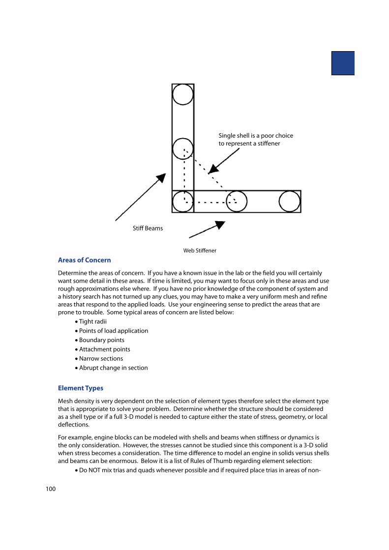
cantilever beam. If there is a high gradient of stress over a large area, for example, a web in the
corner of a frame, many elements may be required to get the proper de%ection.
100
Web Sti#ener
Areas of Concern
Determine the areas of concern. If you have a known issue in the lab or the "eld you will certainly
want some detail in these areas. If time is limited, you may want to focus only in these areas and use
rough approximations else where. If you have no prior knowledge of the component of system and
a history search has not turned up any clues, you may have to make a very uniform mesh and re"ne
areas that respond to the applied loads. Use your engineering sense to predict the areas that are
prone to trouble. Some typical areas of concern are listed below:
Tight radii
Points of load application
Boundary points
Attachment points
Narrow sections
Abrupt change in section
Element Types
Mesh density is very dependent on the selection of element types therefore select the element type
that is appropriate to solve your problem. Determine whether the structure should be considered
as a shell type or if a full 3-D model is needed to capture either the state of stress, geometry, or local
de%ections.
For example, engine blocks can be modeled with shells and beams when sti#ness or dynamics is
the only consideration. However, the stresses cannot be studied since this component is a 3-D solid
when stress becomes a consideration. The time di#erence to model an engine in solids versus shells
and beams can be enormous. Below it is a list of Rules of Thumb regarding element selection:
Do NOT mix trias and quads whenever possible and if required place trias in areas of non-
Single shell is a poor choice
to represent a sti#ener
Sti# Beams

101
concern
Use all trias for back-to-back comparisons when you have determined trias are adequate to
your solution - don’t compare a quad model with a re"ned tria model.
Use elements of consistent size whenever possible
Do NOT combine shells and solids or beams and shells/solids without "rst understanding all
the assumptions and implications to your solution
Model solid parts with solid elements
Model thin plate structures with shell elements ( thickness < 10-20 x Edge length)
Understand all assumptions for the element type you have selected
Do NOT use degenerated elements unless required
Do NOT mix tetrahedral elements with other element types and, if required, place outside
areas of concern
Use tetrahedral elements when the e#ort required to model hexahedral elements is
excessive (This can run into weeks of e#ort versus days for tetras)
Use beam elements when shells or solids require excessive modeling time and e#ort
Beam elements can be used e#ectively in beam-like structures or for fasteners and connections.
However, due to the complexity of employing beam elements, they are probably the most misused
elements in the family of elements. The following considerations make using beam elements a
di$cult process to perform successfully.
Shear center
Warping constraint
Length to depth ratio
Shear de%ection
Complex state of stress near end conditions
Visualizing both the input and the output of beam analysis
Stress results for complex beam sections are only good for global type values computed by classical
beam methods. Beams of circular cross section are an exception because they are easily modeled
and the classical beam results usually match actual performance except at localized end conditions.
Decades of study and research have enabled experts to construct intricate geometry with beam
elements (usually to save computer time) but few individuals understand the complexity of these
techniques. Therefore be prepared to encounter a very involved situation if you choose to employ
this element type.
Timing
Available time is a major determinant in a decision concerning mesh density. A compromise
is usually reached between the amounts of time dedicated to human time and that devoted to
computer time. It is often less time consuming to build a large model by using an automatic mesher,
and increased computer capacity has lessened the need to use special techniques to minimize
the number of elements. Therefore human time has become more focused on productivity and
competitiveness in the market. Pick modeling techniques and elements that provide the most
e$cient blend of factors while simultaneously considering "xed external factors. Once you are
convinced that your decisions are solidly supported, discuss your approach with others before
implementing your plan.
Another important factor in the decision on model complexity is the tendency for models to “live”

102
for an extended period of time. If you feel that the model may have a long life then work at ways
to simply the modi"cation and/or rede"nition to reduce future e#ort. This is an often overlooked
problem and can cause signi"cant time loss.
Mesh Density and Solution Convergence Summary
1. Identify the smallest details that must be captured.
1. Evaluate the level of design detail available.
2. Check for current standards and previous work that will be used for comparison.
3. Estimate the deformed shape and its requirements on your model.
4. Plan for a convergence iteration(s).
5. Select a more detailed modeling approach when stress is important. Consider a two-phase
approach to stress solutions in which you make a second model for detailed work to
reduce the scope and complexity of you solution.
6. Identify known and predicted areas of concern.
7. Select appropriate element type(s). Mix element types only with caution.
8. Consider timing in your approach.


