
International Atomic Energy Agency
Angiography EquipmentAngiography Equipment
L 4

Lecture 4: Angiography equipment 2Radiation Protection in Cardiology
Educational objectivesEducational objectives
• What are equipment standards for cath equipment (FDA, IEC), particular needs for pediatric patients.
• What to look for while establishing a cath lab.
• Importance of testing equipment performance.
Lecture 4: Angiography equipment 3Radiation Protection in Cardiology
Equipment standardsfor Cath Lab

Lecture 4: Angiography equipment 4Radiation Protection in Cardiology
X-Ray Equipment Standards X-Ray Equipment Standards And RegulationsAnd Regulations
• Standards are consensus guides from the manufacturing community, not regulatory
• Several groups set standards regarding equipment, e.g., International Electrotechnical Equipment (IEC)
• Apply to electrical, mechanical, and radiation safety
• Apply to equipment at time of manufacture and installation

Lecture 4: Angiography equipment 5Radiation Protection in Cardiology
What to look for while establishing a What to look for while establishing a cath. lab.cath. lab.
• If the relevant Standards are fulfilled.
• If a medical physicist is available.
• If radiation protection tools are available.
• If patient dose measuring and recording system is available.
• If acceptance tests, commissioning and quality assurance programme have been foreseen.
Lecture 4: Angiography equipment 6Radiation Protection in Cardiology
What to look for while establishing a What to look for while establishing a cath. lab.cath. lab.
• If the X rays system selected is appropriate for the procedures to be carried out in the catheterization laboratory.
• If some other relevant information described in ACC/AHA Guidelines and AAPM-70 (described in this lecture) have been taken into account.

Lecture 4: Angiography equipment 7Radiation Protection in Cardiology
OutlineOutline
• FDA, IEC and ACR recommendations concerning X-ray equipment for cardiology.
• AAPM report and specific pediatric equipment recommendations.
• Key topics for cardiac X-ray equipment.
• IAEA survey and importance of testing equipment.
• Patient dose reports and DICOM header information.
Lecture 4: Angiography equipment 8Radiation Protection in Cardiology
Limitation in entrance exposure rateLimitation in entrance exposure rate
Federal Register: May 19, 1994. 21 CFR Part 1020.Federal Performance Standard for Diagnostic X-Ray Systems and Their Major Components; Final Rule.DEPARTMENT OF HEALTH AND HUMAN SERVICESFood and Drug Administration
Lecture 4: Angiography equipment 9Radiation Protection in Cardiology
Limitation in entrance exposure rateLimitation in entrance exposure rate
• The Standard for Diagnostic X Ray Systems (May 19, 1994), limits the entrance exposure rate of fluoroscopic x ray systems during normal fluoroscopy to 10 R/min unless an optional high-level control (HLC) is activated.
• If HLC is activated, the entrance exposure rate must be limited to 20 R/min.
• The entrance exposure rate limits do not apply during the recording of images.

Lecture 4: Angiography equipment 10Radiation Protection in Cardiology
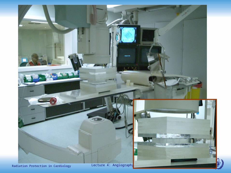
Measuring entrance dose and
image quality
Test object to measure image quality, at the
isocenter
Flat ionisation chamber to
measure phantom entrance dose
Lecture 4: Angiography equipment 11Radiation Protection in Cardiology
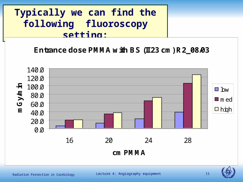
Typically we can find the following fluoroscopy setting:
Entrance dose PMMA with BS (II 23 cm) R2_08/03
0.020.040.060.080.0
100.0120.0140.0
16 20 24 28
cm PMMA
mG
y/m
in low
med
high
Lecture 4: Angiography equipment 12Radiation Protection in Cardiology
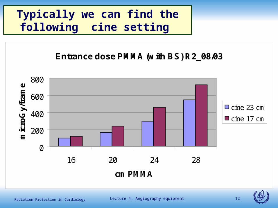
Entrance dose PMMA (with BS) R2_08/03
0
200
400
600
800
16 20 24 28
cm PMMA
mic
roG
y/fr
ame
cine 23 cm
cine 17 cm
Typically we can find the following cine setting
Lecture 4: Angiography equipment 13Radiation Protection in Cardiology
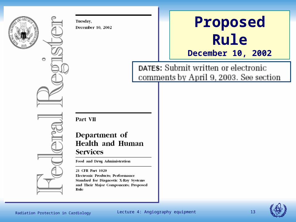
Proposed RuleDecember 10, 2002
Lecture 4: Angiography equipment 14Radiation Protection in Cardiology
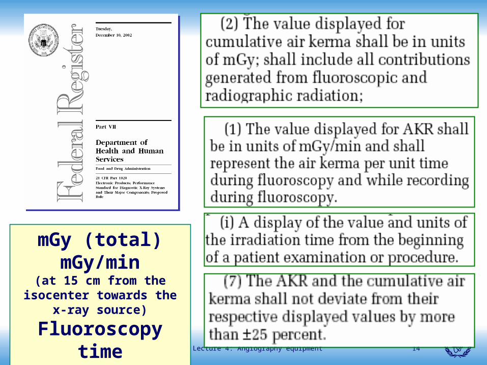
mGy (total)mGy/min
(at 15 cm from the isocenter towards the x-ray source)
Fluoroscopy time
Lecture 4: Angiography equipment 15Radiation Protection in Cardiology
Lecture 4: Angiography equipment 16Radiation Protection in Cardiology
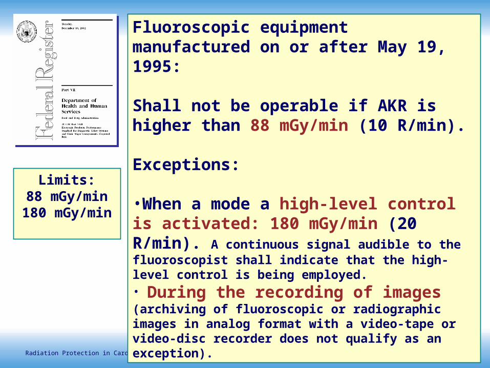
Fluoroscopic equipment manufactured on or after May 19, 1995:
Shall not be operable if AKR is higher than 88 mGy/min (10 R/min).
Exceptions: •When a mode a high-level control is activated: 180 mGy/min (20 R/min). A continuous signal audible to the fluoroscopist shall indicate that the high-level control is being employed.• During the recording of images (archiving of fluoroscopic or radiographic images in analog format with a video-tape or video-disc recorder does not qualify as an exception).
Limits:88 mGy/min
180 mGy/min
Lecture 4: Angiography equipment 17Radiation Protection in Cardiology
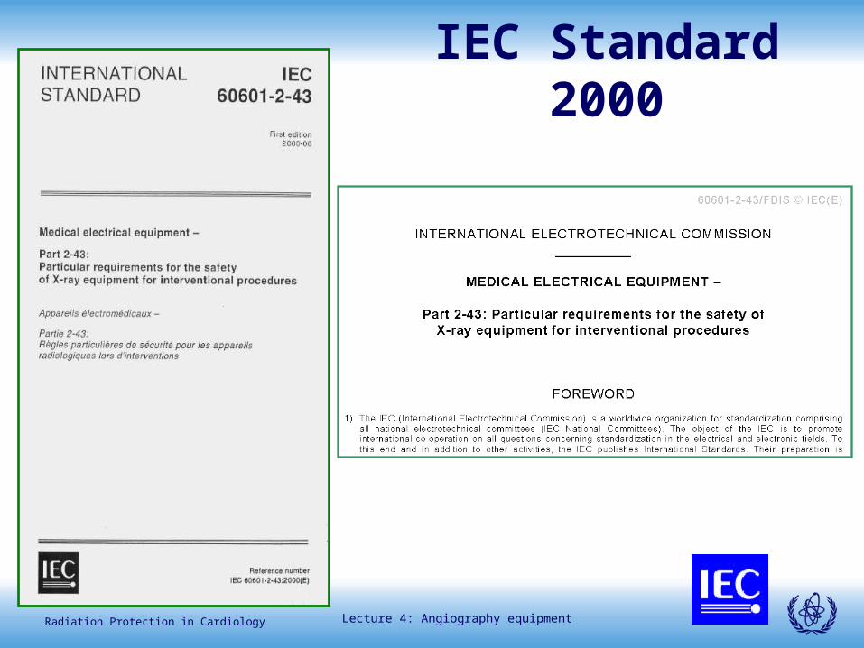
IEC Standard 2000

Lecture 4: Angiography equipment 18Radiation Protection in Cardiology
IEC standard on Interventional IEC standard on Interventional RadiologyRadiology
• Radioscopically guided invasive (and interventional) procedures.
• Interventional reference point.
• Isokerma maps shall be provided.
• The anti-scatter grid should be removable without the use of tools.
• Dosimetric indications: reference air kerma rate, cumulative reference air kerma. cumulative area kerma product, (shall be accurate to within 50 %).
• Supplementary indications: cumulative time of radioscopy, cumulative number of radiographic irradiations, integrated reference air kerma.
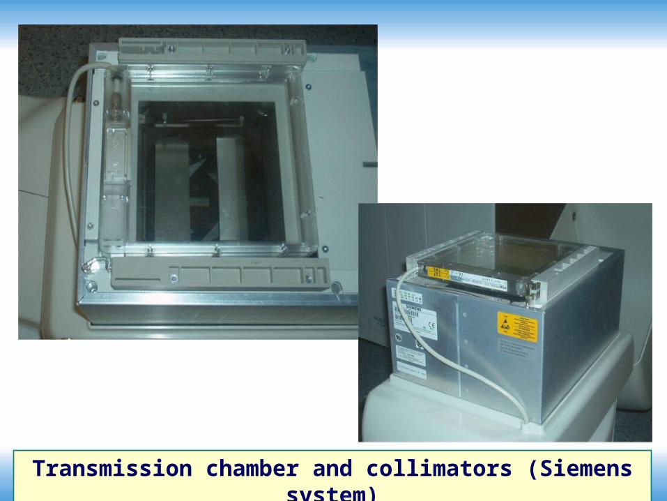
Lecture 4: Angiography equipment 19Radiation Protection in CardiologyTransmission chamber and collimators (Siemens system)

Lecture 4: Angiography equipment 20Radiation Protection in Cardiology

Lecture 4: Angiography equipment 21Radiation Protection in Cardiology
• Collimation: Dual-shape collimators incorporating both circular and elliptical shutters may be used to modify the field for cardiac contour collimation. Partially absorbent contoured filters are also available to control the bright spots produced by the lung tissue bordering the heart.

Lecture 4: Angiography equipment 22Radiation Protection in Cardiology
Philips systems
Lecture 4: Angiography equipment 23Radiation Protection in Cardiology
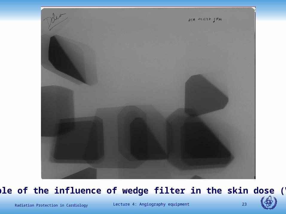
Example of the influence of wedge filter in the skin dose (Vano)

Lecture 4: Angiography equipment 24Radiation Protection in Cardiology
• Image intensifiers. Because of the necessity of imaging large fields (e.g., for ventriculography, aortography) as well as small fields (coronary arteries), multimode (double or triple) cesium iodide image intensifiers are recommended. Formats available vary with the manufacturer but are typically 9 in/ 6 in/4.5 in (9/6/4.5), 9/6, 10/4, and 9/5.
Lecture 4: Angiography equipment 25Radiation Protection in Cardiology
• Patient and Equipment Support: The ability to obtain very steep sagittal plane angulation (in excess of 45 ) is desirable.
• An image intensifier with a diameter of more than 9 in is not recommended for cardiac catheterization laboratories because its size interferes with the ability to obtain steep sagittal angulation.

Lecture 4: Angiography equipment 26Radiation Protection in Cardiology
• The operator should be made aware of the cumulative amount of exposure time during the procedure.
• In training programs there should be a limit to the amount of fluoroscopic time granted to a trainee to complete a specific task, based on a number of considerations such as the progress being made and the complexity of the procedure.

Lecture 4: Angiography equipment 27Radiation Protection in Cardiology
• A freely movable lead glass or acrylic shield suspended from the ceiling should be used. Its sterility may be maintained by using disposable plastic covers.
• Each procedure room should have a detailed determination of exposure levels performed by a qualified radiation physicist.
• There is a tendency in the busy laboratory to assign a low priority to preventive maintenance and quality assurance inspections.

Lecture 4: Angiography equipment 28Radiation Protection in Cardiology
AAPM-70 (2001)AAPM-70 (2001)
• The generator should be capable of generating 80 to 100 kilowatts (kW) of power.
• The generator design should result in “square wave” kVp pulses to achieve optimum patient dose savings.
Lecture 4: Angiography equipment 29Radiation Protection in Cardiology
AAPM-70 (2001)AAPM-70 (2001)
• Several manufacturers are using relatively thick copper filtration and reduced kVp during fluoroscopy to generate an energy spectrum better matched to the K-edge of iodine contrast media.
• This technique requires high fluoroscopic tube currents with the benefit of reducing patient exposure to radiation while improving image contrast.
Lecture 4: Angiography equipment 30Radiation Protection in Cardiology
AAPM-70 (2001)AAPM-70 (2001)
• For adult studies, a 9 to 11 inch (23 to 27 cm) size is used.
• Pediatric cardiac studies use smaller FoVs due to the small size of the pediatric heart.
• The 4.5 inch (11 cm) FoV would be commonly employed for most pediatric imaging studies.
Lecture 4: Angiography equipment 31Radiation Protection in Cardiology
AAPM-70 (2001). Pediatrics.AAPM-70 (2001). Pediatrics.
• If the cath lab will serve the pediatric population, the generator design should allow high quality imaging on patients which range in size from 3 to 140 kilograms (kg).
• This wide range of patient size places additional demands on the design of the generator.
Lecture 4: Angiography equipment 32Radiation Protection in Cardiology
AAPM-70 (2001). Pediatrics.AAPM-70 (2001). Pediatrics.
• The generator design should allow the mAs loading of the tube per cine pulse to be varied from as little as 0.1 mAs (100 mA and 1 msec) up to 6 mAs (e.g., 800 mA and 7 msec) as a function of patient size in order to maintain a kVp operating range of 65 to 75 kVp.
Lecture 4: Angiography equipment 33Radiation Protection in Cardiology
AAPM-70 (2001). Pediatrics.AAPM-70 (2001). Pediatrics.
• Cine frame rate capability should extend up to at least 60 fps for small children.
• The generator should support an x-ray tube with a minimum of three focal spots. Patients up to 3 to 4 years old can be imaged with an 0.3 mm focal spot size, and patients up to
• 8 to 9 years old can be imaged with cine using an 0.6 mm focal spot.

Lecture 4: Angiography equipment 34Radiation Protection in Cardiology
AAPM-70 (2001). Pediatrics.AAPM-70 (2001). Pediatrics.
• The 0.3 mm focal spot can also be used on small children by removing the anti-scatter grid and employing a geometric magnification factor up to 2.
• The geometrical magnification method for small children can also reduce patient dose because the electronic magnification modes of the image intensifier are avoided and the Bucky factor due to the grid is eliminated.

International Atomic Energy Agency
Cardiology equipmentCardiology equipmentkey topicskey topics
Lecture 4: Angiography equipment 36Radiation Protection in Cardiology
Key topicsKey topics• Spatial beam modulation: collimation (and
virtual collimation), wedge filters, etc.
• Temporal beam modulation: pulsed fluoroscopy (grid controlled, temporal integration, etc).
• Beam quality modulation: extra filtering (Cu, Ta, etc).
• Last image hold.
• Patient dose measurement, display and archive.
• New detectors (dynamic flat panel), connectivity and DICOM compliance.

Lecture 4: Angiography equipment 37Radiation Protection in CardiologyControl panel indications (Siemens system)
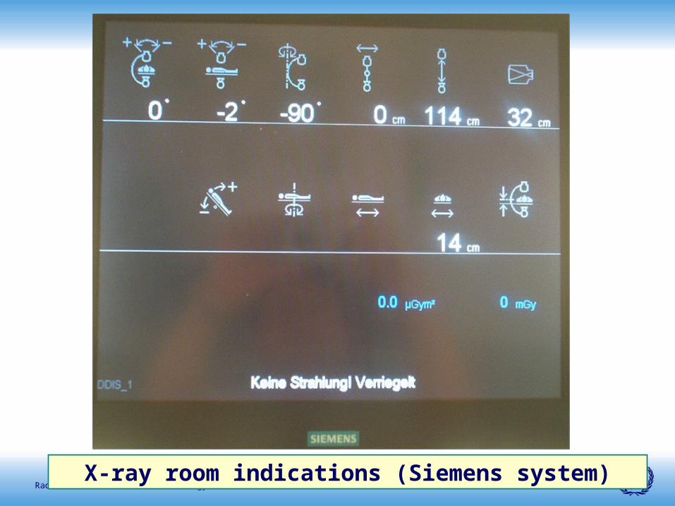
Lecture 4: Angiography equipment 38Radiation Protection in CardiologyX-ray room indications (Siemens system)
Lecture 4: Angiography equipment 39Radiation Protection in Cardiology
Key topicsKey topics
• Ergonomy in the room and system geometry.
• Accidental stop of the system.
• Dosimetric indications in the system and inside the cath lab.
• Protective tools in the system.
• Operational modes and how they are settled.
• DICOM header information.
• On line audit possibilities.

Lecture 4: Angiography equipment 40Radiation Protection in Cardiology
High filtration High filtration
• The introduction of additional filtration in the X ray beam (commonly copper filters) reduce the number of low energy photons and as consequence, saves skin dose for the patients.

Lecture 4: Angiography equipment 41Radiation Protection in Cardiology
• Additional Cu filters can reduce the skin dose by more than 70%.
• Some systems affer variable extra filtration (0.2 mm - 0.9 mm) that is automatically set according to patient weight and angulation of the C-arm.
• Automatic filter insertion try to keep the dose as low as possible without degrading image quality.
Reduction of Radiation Exposure with Reduction of Radiation Exposure with extra filtrationextra filtration

Lecture 4: Angiography equipment 42Radiation Protection in Cardiology
Pulsed fluoroscopyPulsed fluoroscopy
• Pulsed fluoroscopy can be used as a method of reducing radiation dose, particularly when the pulse rate is reduced.
• But … pulsed fluoroscopy does not mean that dose rate is lower in comparison with continuous fluoroscopy!!.
• Dose rate depends of the dose per pulse and the number of pulses per second.
Lecture 4: Angiography equipment 43Radiation Protection in Cardiology
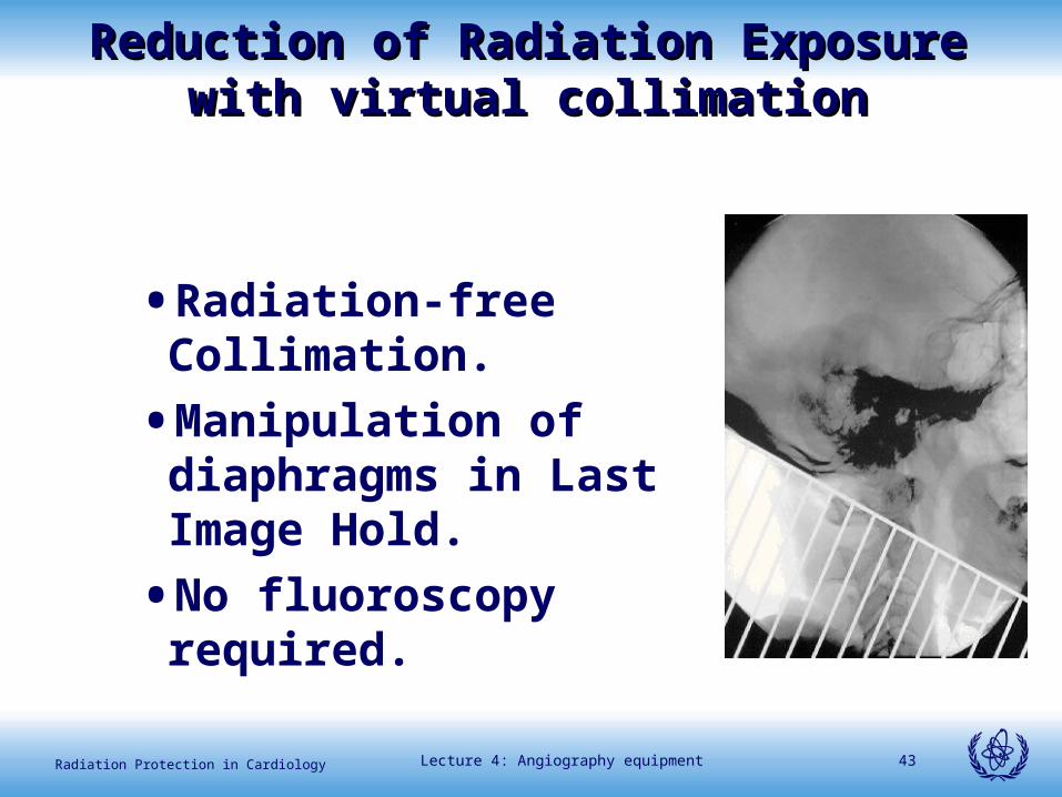
Reduction of Radiation Exposure with Reduction of Radiation Exposure with virtual collimationvirtual collimation
• Radiation-free Collimation.
• Manipulation of diaphragms in Last Image Hold.
• No fluoroscopy required.
International Atomic Energy Agency
Example of X-ray system Example of X-ray system settingsetting
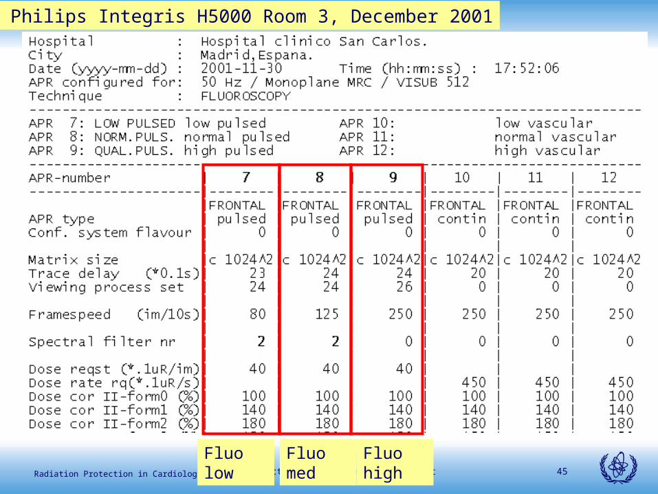
Lecture 4: Angiography equipment 45Radiation Protection in Cardiology
APR Philips Integris H5000 Room 3, December 2001
Fluo low Fluo med Fluo high
International Atomic Energy Agency
IAEA survey 2001-2003IAEA survey 2001-2003
X-ray systems evaluated:
9-15 from 5 countries

Lecture 4: Angiography equipment 47Radiation Protection in Cardiology
95
45
125
118
102
171
39
17
46
0
20
40
60
80
100
120
140
160
180m
icro
Gy
/fra
me
Integris BH3000 Uru
Picker CV-PRO Uru
Integris 5000 R3 Sp
Integris 5000 R4 Sp
Integris 3000 R2 Sp
GE Advantx LCV Sp
Siemens II yell Lu
Siemens flat yell Lu
GE Advantx CFM Chile
Cine mode 16 cm PMMA
Very different dose/frame values have been found
Lecture 4: Angiography equipment 48Radiation Protection in Cardiology
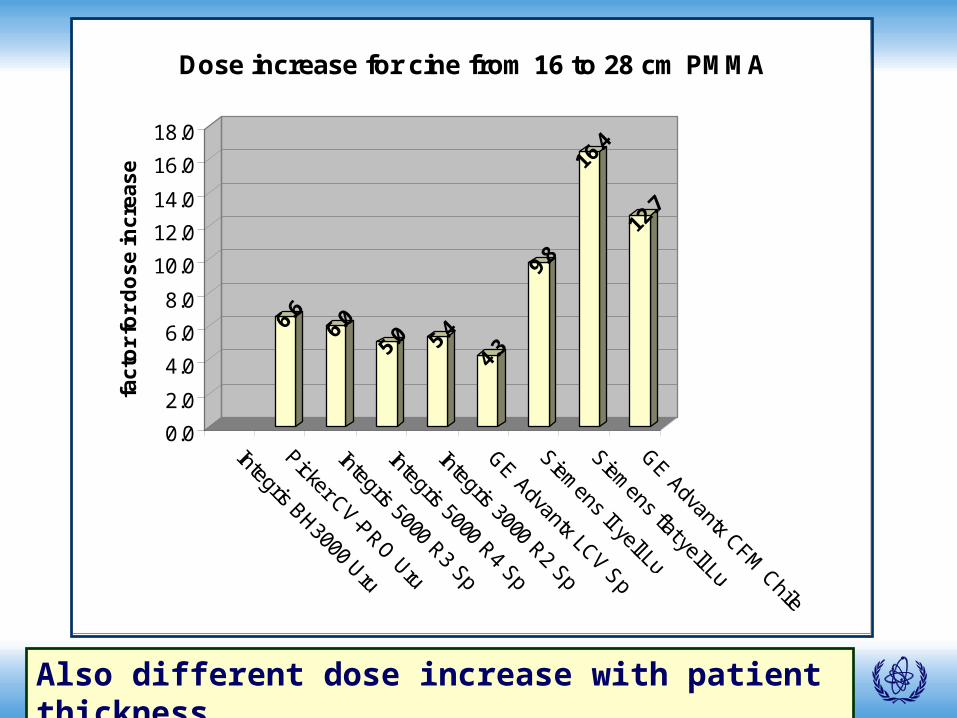
6.6
6.0
5.0 5.
4
4.3
9.8
16.4
12.7
0.0
2.0
4.0
6.0
8.0
10.0
12.0
14.0
16.0
18.0fa
cto
r fo
r d
os
e in
cre
as
e
Integris BH3000 Uru
Picker CV-PRO Uru
Integris 5000 R3 Sp
Integris 5000 R4 Sp
Integris 3000 R2 Sp
GE Advantx LCV Sp
Siemens II yell Lu
Siemens flat yell Lu
GE Advantx CFM Chile
Dose increase for cine from 16 to 28 cm PMMA
Also different dose increase with patient thickness
Lecture 4: Angiography equipment 49Radiation Protection in Cardiology
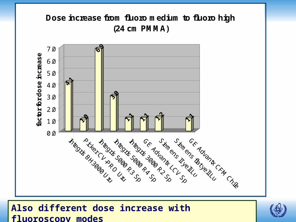
4.1
1.0
6.9
3.0
1.1
1.1 1.
21.
1
0.0
1.0
2.0
3.0
4.0
5.0
6.0
7.0
fac
tor
for
do
se
inc
rea
se
Integris BH3000 Uru
Picker CV-PRO Uru
Integris 5000 R3 Sp
Integris 5000 R4 Sp
Integris 3000 R2 Sp
GE Advantx LCV Sp
Siemens II yell Lu
Siemens flat yell Lu
GE Advantx CFM Chile
Dose increase from fluoro medium to fluoro high (24 cm PMMA)
Also different dose increase with fluoroscopy modes

Lecture 4: Angiography equipment 50Radiation Protection in Cardiology
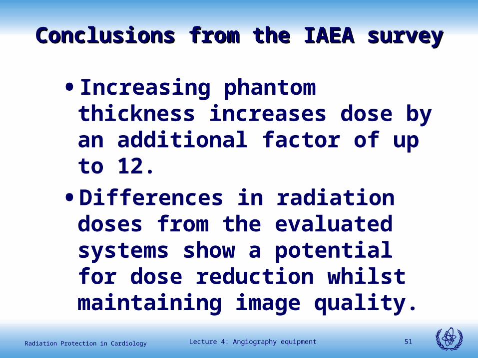
Conclusions from the IAEA surveyConclusions from the IAEA survey
• Patient dose and image quality depend largely on the settings made at the commissioning of the radiological equipment.
• For different systems and different operation modes, entrance air kerma can increase by a factor of 20 (including electronic magnification) for the same patient thickness.
Lecture 4: Angiography equipment 51Radiation Protection in Cardiology
• Increasing phantom thickness increases dose by an additional factor of up to 12.
• Differences in radiation doses from the evaluated systems show a potential for dose reduction whilst maintaining image quality.
Conclusions from the IAEA surveyConclusions from the IAEA survey

Lecture 4: Angiography equipment 52Radiation Protection in Cardiology
Importance of testing X ray equipmentImportance of testing X ray equipment
• Characterization of the X- ray system, that should be part of the acceptance and status tests, should inform cardiologists about the dose rates and dose/frame for the different operation modes and for the different patient thicknesses. Image quality shall also be evaluated.
• Regular constancy checks should verify if important changes could been occurred.
International Atomic Energy Agency
Examples of patient dose Examples of patient dose reportsreports

Lecture 4: Angiography equipment 54Radiation Protection in Cardiology
1 CARD FIXED Coro ND 1k 7s 15F/s 15-Jan-03 09:16:21A 81kV 744mA 6.0ms 200CL small 0.3Cu 17cm 211.4µGym² 36.2mGy 0LAO 0CRA 105F
2 CARD FIXED Coro ND 1k 6s 15F/s 15-Jan-03 09:17:01A 86kV 734mA 6.0ms 600CL small 0.2Cu 17cm 376.9µGym² 63.8mGy 29RAO 0CRA 94F
3 CARD FIXED Coro ND 1k 5s 15F/s 15-Jan-03 09:17:43A 124kV 553mA 8.0ms ****** small 0.2Cu 17cm 490.3µGym² 94.1mGy 48RAO 22CRA 75F
4 CARD FIXED Coro ND 1k 6s 15F/s 15-Jan-03 09:18:16A 115kV 591mA 8.0ms ****** small 0.2Cu 17cm 460.4µGym² 97.8mGy 48RAO 22CRA 84F
5 CARD FIXED Coro ND 1k ***** 15F/s 15-Jan-03 09:19:05A 96kV 714mA 8.0ms ****** small 0.2Cu 17cm 9.3µGym² 1.9mGy 15RAO 30CRA 2F
6 CARD FIXED Coro ND 1k ***** 15F/s 15-Jan-03 09:19:07A 102kV 666mA 8.0ms ****** small 0.2Cu 17cm 17.2µGym² 3.5mGy 15RAO 30CRA 3F
Example of the data included in the study report (Siemens)

Lecture 4: Angiography equipment 55Radiation Protection in Cardiology
Example of the data included in the dosimetric report (Philips):
Philips Integris 5000:
Coronary angiography
65% cine; 35% fluoroscopy
13 series, 728 frames
1,54 Gy.cm2/min
0,368 Gy.cm2/10 fr
1 min fluoroscopy =
39 fr = 3 s cine
International Atomic Energy Agency
Examples of information Examples of information contained at the DICOM contained at the DICOM
headerheader

Lecture 4: Angiography equipment 57Radiation Protection in Cardiology
GE ADVANTX LCV-DLX (Cardio mode)(0008,0032) : Acquisition Time : 19:24:33(0008,103E) : Series Description : CORONARIO(0018,0060) : KVP : 75(0018,1110) : Distance Source to Detector : 1060.000(0018,1111) : Distance Source to Patient : 705(0018,1149) : Field of View Dimension(s) 152(0018,1150) : Exposure Time : 328 (number fr x ms per fr)(0018,1151) : X-ray Tube Current : 81(0018,1510) : Positioner Primary Angle : -30 (left is +)(0018,1511) : Positioner Secondary Angle : 0 (cra is +)(0019,101B) : 1.2 (this is the focus size)(0019,101C) : 1 (Dose mode: 0,1, 2 and 3 for A,B,C and D)(0019,101F) : 4 (This is the real pulse time in ms)(0020,0013) : Image Number : 2 (this is the series number)(0028,0008) : Number of Frames : 82
Lecture 4: Angiography equipment 58Radiation Protection in Cardiology
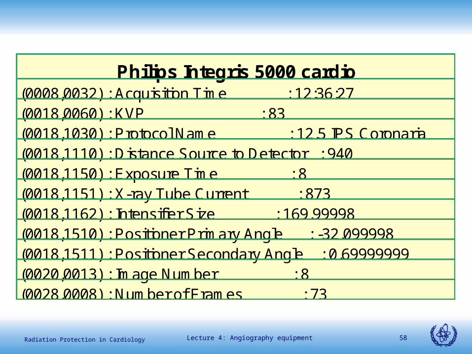
Philips Integris 5000 cardio(0008,0032) : Acquisition Time : 12:36:27(0018,0060) : KVP : 83(0018,1030) : Protocol Name : 12.5 IPS Coronaria(0018,1110) : Distance Source to Detector : 940(0018,1150) : Exposure Time : 8(0018,1151) : X-ray Tube Current : 873(0018,1162) : Intensifier Size : 169.99998(0018,1510) : Positioner Primary Angle : -32.099998(0018,1511) : Positioner Secondary Angle : 0.69999999(0020,0013) : Image Number : 8(0028,0008) : Number of Frames : 73
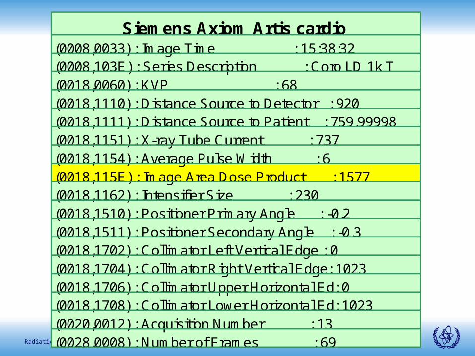
Lecture 4: Angiography equipment 59Radiation Protection in Cardiology
Siemens Axiom Artis cardio (0008,0033) : Image Time : 15:38:32(0008,103E) : Series Description : Coro LD 1k T(0018,0060) : KVP : 68(0018,1110) : Distance Source to Detector : 920(0018,1111) : Distance Source to Patient : 759.99998(0018,1151) : X-ray Tube Current : 737(0018,1154) : Average Pulse Width : 6(0018,115E) : Image Area Dose Product : 1577(0018,1162) : Intensifier Size : 230(0018,1510) : Positioner Primary Angle : -0.2(0018,1511) : Positioner Secondary Angle : -0.3(0018,1702) : Collimator Left Vertical Edge : 0(0018,1704) : Collimator Right Vertical Edge: 1023(0018,1706) : Collimator Upper Horizontal Ed: 0(0018,1708) : Collimator Lower Horizontal Ed: 1023(0020,0012) : Acquisition Number : 13(0028,0008) : Number of Frames : 69

Lecture 4: Angiography equipment 60Radiation Protection in Cardiology
SummarySummary
• What to look for while establishing a cath lab
• FDA, IEC, ACR recommendations
• Specific aspects in paediatrics• Examples of patient dose
reports• Dose variation in cine & fluoro-
IAEA survey• DICOM header information


