
512-Mbit SDRAMmemory extender
Power ICDI-JTAG
256-MBit 16-bit
SDRAMTM4C129XNCZAD
10/100
Ethernet
QVGA Smart LCD Panel
Dual
16x2
Connector
EPI
Interface
TI DesignsInterfacing SDRAM on High-Performance MicrocontrollersDesign Guide
TI Designs Design FeaturesTI Designs provide the foundation that you need • DK-TM4C129X EVM (formerly Tiva™ MCU) Withincluding methodology, testing, and design files to Integrated Smart QVGA LCD Panel For Graphicsquickly evaluate and customize the system. TI Designs Renderinghelp you accelerate your time to market. • 512-Mbit 16-bit SDRAM With 60-MHz EPI Interface
For High-Memory Throughput And FootprintDesign Resources Applications• Driver Library Components To Simplify CodeTool Folder Containing Design FilesTIDM-TM4C129XSDRAM
DevelopmentTIDM-CONNECTED- Tool FolderETHERNET • Source Code With Project For Code ComposerTM4C129XNCZAD Product Folder Studio™TM4C123GH6PM Product Folder
Featured ApplicationsTPS2051B Product FolderLM4819 Product Folder • Interactive Human Machine InterfacesTPS62177 Product Folder • IoT SolutionsREF3230 Product Folder • Industrial AutomationTMP100 Product Folder
ASK Our E2E ExpertsWEBENCH® Calculator Tools
An IMPORTANT NOTICE at the end of this TI reference design addresses authorized use, intellectual property matters and otherimportant disclaimers and information.
All trademarks are the property of their respective owners.
1TIDU853–March 2015 Interfacing SDRAM on High-Performance Microcontrollers Design GuideSubmit Documentation Feedback
Copyright © 2015, Texas Instruments Incorporated

System Description www.ti.com
1 System DescriptionThe interfacing of the TM4C129x family of microcontrollers to an external memory can be used todownload and execute code and data when the internal memory is not sufficient for a large userapplication. This application note describes the requirements for hardware interfacing and softwareexample codes for TM4C129x microcontrollers from Texas Instruments for external 512-Mbit 16-bit accessSDRAM.
The design files include Schematics, BOM, Layer plots, Altium files, Gerber, and reference example codesfor easy-to-use SDRAM with the TM4C129XNCZAD EVM kit.
1.1 TM4C129XNCZADTM4C129XNCZAD is 120-MHz high-performance microcontroller with 1-MB on-chip Flash and 256-KB on-chip SRAM. This microcontroller features an integrated Ethernet MAC+PHY for connected applications.The device has high bandwidth interfaces like an LCD controller, memory controller, and a high-speedUSB 2.0 digital interface. With integration of a number of low- to mid-speed serials, up to 4-MSPS 12-bitADC, and motion control peripherals, the device makes for a unique solution for a variety of applicationsranging from industrial communication equipments to smart energy and smart grid applications.
2 Interfacing SDRAM on High-Performance Microcontrollers Design Guide TIDU853–March 2015Submit Documentation Feedback
Copyright © 2015, Texas Instruments Incorporated

TM4C129XNCZAD
ARM®Cortex™-M4F
(120MHz)
NVIC MPU
FPUETMFlash
(1024KB)
Boot Loader
DriverLib
AES & CRC
Ethernet Boot Loader
ROM
DCode bus
ICode bus
JTAG/SWD
SystemControl and
Clocks(w/ Precis. Osc.)
Bus Matrix
System Bus
SRAM(256KB)
SYSTEM PERIPHERALS
WatchdogTimer
(2 Units)DMA
HibernationModule
Tamper
EEPROM(6K)
General-Purpose
Timer (8 Units)
GPIOs(140)
ExternalPeripheralInterface
CRCModule
AESModule
DESModule
SHA/MD5Module
TFT LCDController
SERIAL PERIPHERALS
UART(8 Units)
USB OTG(FS PHYor ULPI)
I2C(10 Units)
SSI(4 Units)
CANController(2 Units)
EthernetMAC/PHY/MII
ANALOG PERIPHERALS
12- Bit ADC(2 Units /
24 Channels)
AnalogComparator
(3 Units)
MOTION CONTROL PERIPHERALS
QEI(1 Units)
PWM(1 Units /8 Signals)
SMC PERIPHERALS
1-Wire(1 Units)
Advanced
Periphera
lB
us
(AP
B)
Advanced
Hig
h-P
erf
orm
ance
Bus
(AH
B)
www.ti.com System Description
Figure 1. TM4C129XNCZAD Microcontroller High-Level Block Diagram
3TIDU853–March 2015 Interfacing SDRAM on High-Performance Microcontrollers Design GuideSubmit Documentation Feedback
Copyright © 2015, Texas Instruments Incorporated

Power ICDI-JTAG
256-MBit 16-bit
SDRAMTM4C129XNCZAD
10/100
Ethernet
QVGA Smart LCD Panel
Dual
16x2
Connector
EPI
Interface
Block Diagram www.ti.com
2 Block Diagram
Figure 2. SDRAM Extender Block Diagram
4 Interfacing SDRAM on High-Performance Microcontrollers Design Guide TIDU853–March 2015Submit Documentation Feedback
Copyright © 2015, Texas Instruments Incorporated
Unconnected pins 1 and 2 ofJ27 and J28
www.ti.com Getting Started Hardware
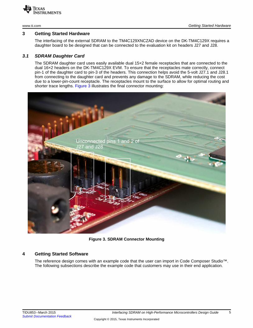
3 Getting Started HardwareThe interfacing of the external SDRAM to the TM4C129XNCZAD device on the DK-TM4C129X requires adaughter board to be designed that can be connected to the evaluation kit on headers J27 and J28.
3.1 SDRAM Daughter CardThe SDRAM daughter card uses easily available dual 15×2 female receptacles that are connected to thedual 16×2 headers on the DK-TM4C129X EVM. To ensure that the receptacles mate correctly, connectpin-1 of the daughter card to pin-3 of the headers. This connection helps avoid the 5-volt J27.1 and J28.1from connecting to the daughter card and prevents any damage to the SDRAM, while reducing the costdue to a lower-pin-count receptacle. The receptacles mount to the surface to allow for optimal routing andshorter trace lengths. Figure 3 illustrates the final connector mounting:
Figure 3. SDRAM Connector Mounting
4 Getting Started SoftwareThe reference design comes with an example code that the user can import in Code Composer Studio™.The following subsections describe the example code that customers may use in their end application.
5TIDU853–March 2015 Interfacing SDRAM on High-Performance Microcontrollers Design GuideSubmit Documentation Feedback
Copyright © 2015, Texas Instruments Incorporated

SDRAM Memory Extender
USB Connector for Power, JTAG,and UART Serial Console
Getting Started Software www.ti.com
4.1 SDRAM Throughput Performance-Example CodeThe SDRAM throughput performance-example code configures the I/O’s of TM4C129XNCZAD to becontrolled by the EPI module. This example then configures the EPI module for the 512-Mbit SDRAM withinterface frequency of 60 MHz. On successful initialization, the SDRAM performs a write of 4-K bytes andmeasures the time taken using the SysTick timer to compute the bandwidth. After completing the write,the SDRAM performs a read of the 4-K bytes and measures the time taken using the SysTick timer tocompute the bandwidth. The operations performed are with 16-bit, 32-bit, and 64-bit words.
5 Test SetupThe test setup involves importing the example code into Code Composer Studio, building the same, andexecuting the code on the DK-TM4C129X EVM. Section 6 shows the results of the example that acustomer may expect and a scope view of the SDRAM clock.
NOTE: The use of the examples assumes that Serial Console Application (PuTTY, TeraTerm, andothers), Code Composer Studio v6.0.1, and TivaWare Full Installation Software release2.1.0-12573 have already been downloaded and installed on the PC.
5.1 Hardware SetupFigure 4 shows the full setup. The USB cable that comes as a part of the DK-TM4C129X EVM (shown onthe top right) provides power, JTAG for debug, and UART for the serial console to the EVM and theSDRAM memory extender. The SDRAM memory extender is connected on the left side of the image tothe headers J27 and J28.
Figure 4. Full Test Assembly
6 Interfacing SDRAM on High-Performance Microcontrollers Design Guide TIDU853–March 2015Submit Documentation Feedback
Copyright © 2015, Texas Instruments Incorporated

www.ti.com Test Setup
5.2 Software SetupFollow these steps to set up the software:
1. Download the software examples zip package from the TI Design web page and unzip the file on thelocal PC.
2. Launch Code Composer Studio v6.0.1 or later. To import the project, click File → Import → CCSProjects, then click “Next”. Browse to the directory where the software examples are kept. Select theproject “dktm4c129_sdram_performance_example”, and click “Finish”.
Figure 5. Importing the Software Example
3. Build the project by right clicking the project and then selecting “Rebuild Project”. The project mustcompile without any errors.
7TIDU853–March 2015 Interfacing SDRAM on High-Performance Microcontrollers Design GuideSubmit Documentation Feedback
Copyright © 2015, Texas Instruments Incorporated

SuccessfulBuild Message
Test Setup www.ti.com
Figure 6. Compiling the Software Example
4. Run the example by pressing the Debug button, which will load the code into the TM4C129XNCZADFlash. Press the Play button after the code has loaded. On a serial console, users must see thefollowing message including the bandwidth computed for the write and read to the SDRAM.
Figure 7. Expected Console Output for the Software Example
8 Interfacing SDRAM on High-Performance Microcontrollers Design Guide TIDU853–March 2015Submit Documentation Feedback
Copyright © 2015, Texas Instruments Incorporated

www.ti.com Test Data
6 Test DataThe following section highlights the performance data and electrical signal integrity of the SDRAM clockpin during the transactions.
6.1 SDRAM Performance DataThe example code for the SDRAM performance test is a bare-metal example and may only be used as areference when ensuring that all hardware connections are correct. Based on the DK-TM4C129X EVMand with a system frequency of 120 MHz, the maximum SDRAM clock achievable is 60 MHz. Table 1computes the bandwidth for the different Write and Read operations via the Cortex-M4 CPU:
Table 1. Performance of SDRAM with EPI in Different Burst Modes
SDRAM WRITE THROUGHPUT SDRAM READ THROUGHPUT16-BIT WORD 39.6711 MBps 16.282 MBps32-BIT WORD (BURST SIZE OF 2) 59.2587 MBps 29.884 MBps64-BIT WORD (BURST SIZE OF 4) 78.4878 MBps 42.889 MBps
6.2 SDRAM Electrical Signal IntegrityThe waveform plot in Figure 8 shows the signal behavior of EPI0S31, which is the SDRAM clock from theTM4C129XNCZAD device to the SDRAM during active Write and Read transactions.
Figure 8. SDRAM Clock Signal Integrity
9TIDU853–March 2015 Interfacing SDRAM on High-Performance Microcontrollers Design GuideSubmit Documentation Feedback
Copyright © 2015, Texas Instruments Incorporated

Single Trace fromConnector to Pad toreduce reflections
Design Files www.ti.com
7 Design Files
7.1 SchematicsTo download the Schematics for each board, see the design files at TIDM-TM4C129XSDRAM.
7.2 Bill of MaterialsTo download the bill of materials (BOM), see the design files at TIDM-TM4C129XSDRAM.
7.3 PCB Layout RecommendationsWhen performing the layout, ensure that the EPI0S31 (the SDRAM clock pin) has the shortest trace. Also,minimize reflections from the shared data and address pins, and use a single route from the connector pinto either the address or data pin without creating a stub. Please see Section 7.6.
7.4 Layer PlotsTo download the layer plots, see the design files at TIDM-TM4C129XSDRAM.
7.5 Altium ProjectTo download the Altium project files, see the design files at TIDM-TM4C129XSDRAM.
7.6 Layout Guidelines
Figure 9. Layout Guidelines for Reducing Reflections
7.7 Gerber FilesTo download the Gerber files, see the design files at TIDM-TM4C129XSDRAM.
10 Interfacing SDRAM on High-Performance Microcontrollers Design Guide TIDU853–March 2015Submit Documentation Feedback
Copyright © 2015, Texas Instruments Incorporated

www.ti.com Design Files
7.8 Software FilesTo download the software files, see the design files at TIDM-TM4C129XSDRAM.
8 References
1. ISSI 512Mbit SDRAM Memory (http://www.issi.com/WW/pdf/42-45R-S_86400D-16320D-32160D.pdf)
11TIDU853–March 2015 Interfacing SDRAM on High-Performance Microcontrollers Design GuideSubmit Documentation Feedback
Copyright © 2015, Texas Instruments Incorporated
About the Author www.ti.com
9 About the AuthorAMIT ASHARA is an Application Engineer at Texas Instruments, where he is responsible for developingapplications for the TM4C12x family of high-performance microcontrollers. Amit brings to this role hisextensive experience in high-speed digital and microcontroller system-level design expertise. Amit earnedhis Bachelor of Engineering (BE) from University of Pune, India.
12 Interfacing SDRAM on High-Performance Microcontrollers Design Guide TIDU853–March 2015Submit Documentation Feedback
Copyright © 2015, Texas Instruments Incorporated

IMPORTANT NOTICE FOR TI REFERENCE DESIGNS
Texas Instruments Incorporated ("TI") reference designs are solely intended to assist designers (“Buyers”) who are developing systems thatincorporate TI semiconductor products (also referred to herein as “components”). Buyer understands and agrees that Buyer remainsresponsible for using its independent analysis, evaluation and judgment in designing Buyer’s systems and products.TI reference designs have been created using standard laboratory conditions and engineering practices. TI has not conducted anytesting other than that specifically described in the published documentation for a particular reference design. TI may makecorrections, enhancements, improvements and other changes to its reference designs.Buyers are authorized to use TI reference designs with the TI component(s) identified in each particular reference design and to modify thereference design in the development of their end products. HOWEVER, NO OTHER LICENSE, EXPRESS OR IMPLIED, BY ESTOPPELOR OTHERWISE TO ANY OTHER TI INTELLECTUAL PROPERTY RIGHT, AND NO LICENSE TO ANY THIRD PARTY TECHNOLOGYOR INTELLECTUAL PROPERTY RIGHT, IS GRANTED HEREIN, including but not limited to any patent right, copyright, mask work right,or other intellectual property right relating to any combination, machine, or process in which TI components or services are used.Information published by TI regarding third-party products or services does not constitute a license to use such products or services, or awarranty or endorsement thereof. Use of such information may require a license from a third party under the patents or other intellectualproperty of the third party, or a license from TI under the patents or other intellectual property of TI.TI REFERENCE DESIGNS ARE PROVIDED "AS IS". TI MAKES NO WARRANTIES OR REPRESENTATIONS WITH REGARD TO THEREFERENCE DESIGNS OR USE OF THE REFERENCE DESIGNS, EXPRESS, IMPLIED OR STATUTORY, INCLUDING ACCURACY ORCOMPLETENESS. TI DISCLAIMS ANY WARRANTY OF TITLE AND ANY IMPLIED WARRANTIES OF MERCHANTABILITY, FITNESSFOR A PARTICULAR PURPOSE, QUIET ENJOYMENT, QUIET POSSESSION, AND NON-INFRINGEMENT OF ANY THIRD PARTYINTELLECTUAL PROPERTY RIGHTS WITH REGARD TO TI REFERENCE DESIGNS OR USE THEREOF. TI SHALL NOT BE LIABLEFOR AND SHALL NOT DEFEND OR INDEMNIFY BUYERS AGAINST ANY THIRD PARTY INFRINGEMENT CLAIM THAT RELATES TOOR IS BASED ON A COMBINATION OF COMPONENTS PROVIDED IN A TI REFERENCE DESIGN. IN NO EVENT SHALL TI BELIABLE FOR ANY ACTUAL, SPECIAL, INCIDENTAL, CONSEQUENTIAL OR INDIRECT DAMAGES, HOWEVER CAUSED, ON ANYTHEORY OF LIABILITY AND WHETHER OR NOT TI HAS BEEN ADVISED OF THE POSSIBILITY OF SUCH DAMAGES, ARISING INANY WAY OUT OF TI REFERENCE DESIGNS OR BUYER’S USE OF TI REFERENCE DESIGNS.TI reserves the right to make corrections, enhancements, improvements and other changes to its semiconductor products and services perJESD46, latest issue, and to discontinue any product or service per JESD48, latest issue. Buyers should obtain the latest relevantinformation before placing orders and should verify that such information is current and complete. All semiconductor products are soldsubject to TI’s terms and conditions of sale supplied at the time of order acknowledgment.TI warrants performance of its components to the specifications applicable at the time of sale, in accordance with the warranty in TI’s termsand conditions of sale of semiconductor products. Testing and other quality control techniques for TI components are used to the extent TIdeems necessary to support this warranty. Except where mandated by applicable law, testing of all parameters of each component is notnecessarily performed.TI assumes no liability for applications assistance or the design of Buyers’ products. Buyers are responsible for their products andapplications using TI components. To minimize the risks associated with Buyers’ products and applications, Buyers should provideadequate design and operating safeguards.Reproduction of significant portions of TI information in TI data books, data sheets or reference designs is permissible only if reproduction iswithout alteration and is accompanied by all associated warranties, conditions, limitations, and notices. TI is not responsible or liable forsuch altered documentation. Information of third parties may be subject to additional restrictions.Buyer acknowledges and agrees that it is solely responsible for compliance with all legal, regulatory and safety-related requirementsconcerning its products, and any use of TI components in its applications, notwithstanding any applications-related information or supportthat may be provided by TI. Buyer represents and agrees that it has all the necessary expertise to create and implement safeguards thatanticipate dangerous failures, monitor failures and their consequences, lessen the likelihood of dangerous failures and take appropriateremedial actions. Buyer will fully indemnify TI and its representatives against any damages arising out of the use of any TI components inBuyer’s safety-critical applications.In some cases, TI components may be promoted specifically to facilitate safety-related applications. With such components, TI’s goal is tohelp enable customers to design and create their own end-product solutions that meet applicable functional safety standards andrequirements. Nonetheless, such components are subject to these terms.No TI components are authorized for use in FDA Class III (or similar life-critical medical equipment) unless authorized officers of the partieshave executed an agreement specifically governing such use.Only those TI components that TI has specifically designated as military grade or “enhanced plastic” are designed and intended for use inmilitary/aerospace applications or environments. Buyer acknowledges and agrees that any military or aerospace use of TI components thathave not been so designated is solely at Buyer's risk, and Buyer is solely responsible for compliance with all legal and regulatoryrequirements in connection with such use.TI has specifically designated certain components as meeting ISO/TS16949 requirements, mainly for automotive use. In any case of use ofnon-designated products, TI will not be responsible for any failure to meet ISO/TS16949.IMPORTANT NOTICE
Mailing Address: Texas Instruments, Post Office Box 655303, Dallas, Texas 75265Copyright © 2015, Texas Instruments Incorporated


