Strategisk høgskoleprosjekt:
Integrated Machinery SystemsIntegrated Machinery Systems(IMAS)
Design, Modelling og Simulationg , g g
In colaboration with:
Offshore Simulation Centre (OSC)Industrial partners in NCE – MaritimeIndustrial partners in NCE MaritimeNTNU, Instit. For Marine Technology,
MARINTEK, Energy, Systems and Environment,
Objectives
Develop knowledge, methods and tools for design and analysis of integrated machinery systems. g y y
Develop a common platform for systems modeling and simulation, which can be used in design optimization verification and operational trainingcan be used in design, optimization, verification and operational training.
Establish multi-diciplinary research group, in close cooperation with selected universities and industrial partnersselected universities and industrial partners.
Develop courses and education of internationally recognized Msc and PhD did t (i ll b ti ith NTNU d th i iti )candidates (in collaboration with NTNU and other universities)
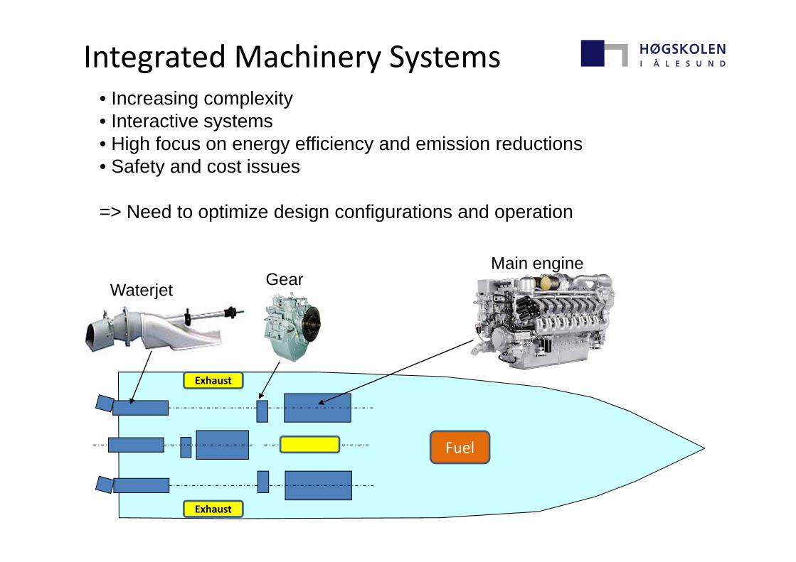
Integrated Machinery Systems• Increasing complexity• Interactive systems• High focus on energy efficiency and emission reductionsg gy y• Safety and cost issues
=> Need to optimize design configurations and operation
GearMain engine
Need to optimize design configurations and operation
Waterjet Gear
Exhaust
Fuel
Exhaust
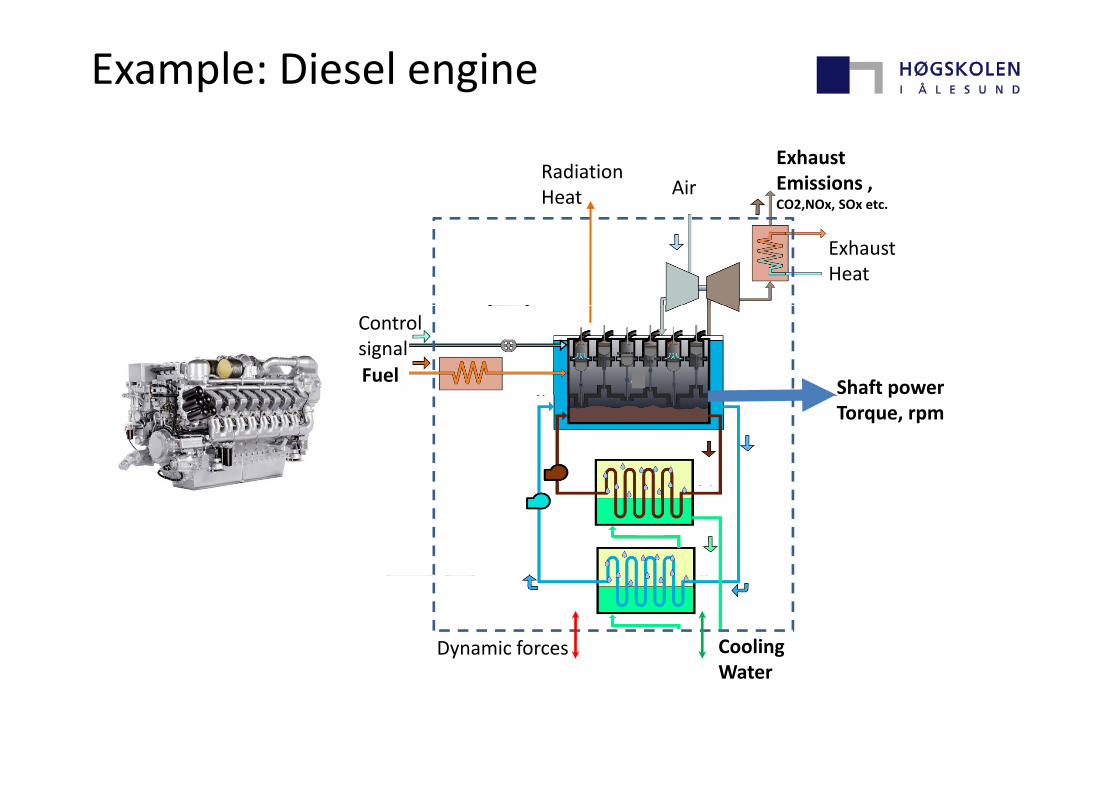
Example: Diesel engine
ExhaustEmissions , CO2,NOx, SOx etc.
AirRadiationHeat
ExhaustHeat
Fuel Shaft power
Control signal
pTorque, rpm
Cooling Dynamic forcesWater
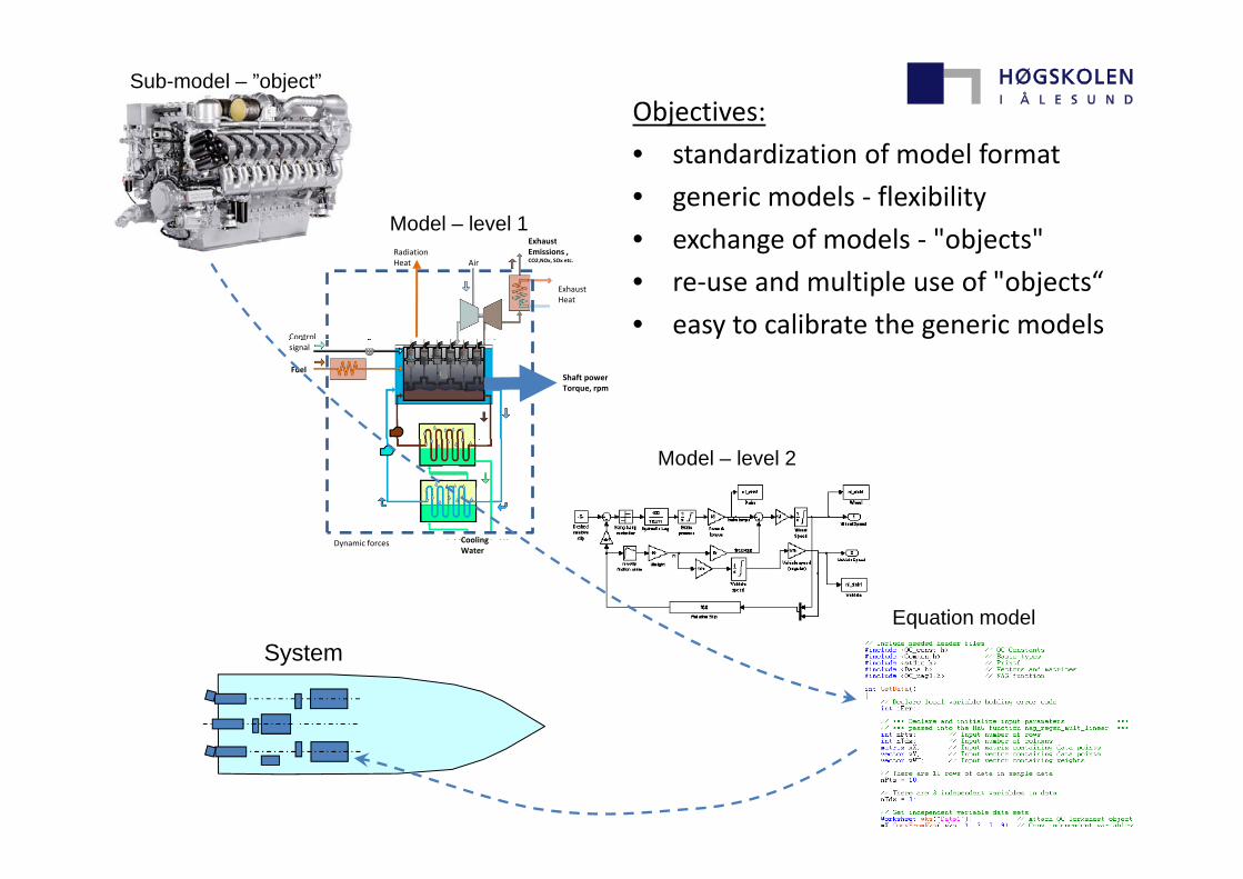
Sub-model – ”object”Objectives:
Exhaust
Model – level 1
• standardization of model format
• generic models ‐ flexibility
• exchange of models ‐ "objects"ExhaustEmissions , CO2,NOx, SOx etc.
ExhaustHeat
AirRadiationHeat
Control
• exchange of models ‐ objects
• re‐use and multiple use of "objects“
• easy to calibrate the generic modelsFuel
Shaft powerTorque, rpm
signal
Cooling
Model – level 2
Cooling Water
Dynamic forces
Equation model
System
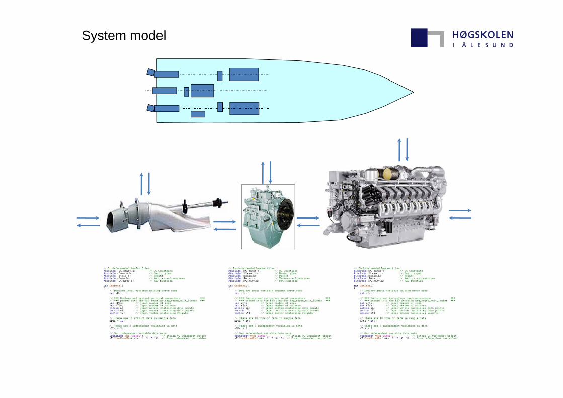
System model
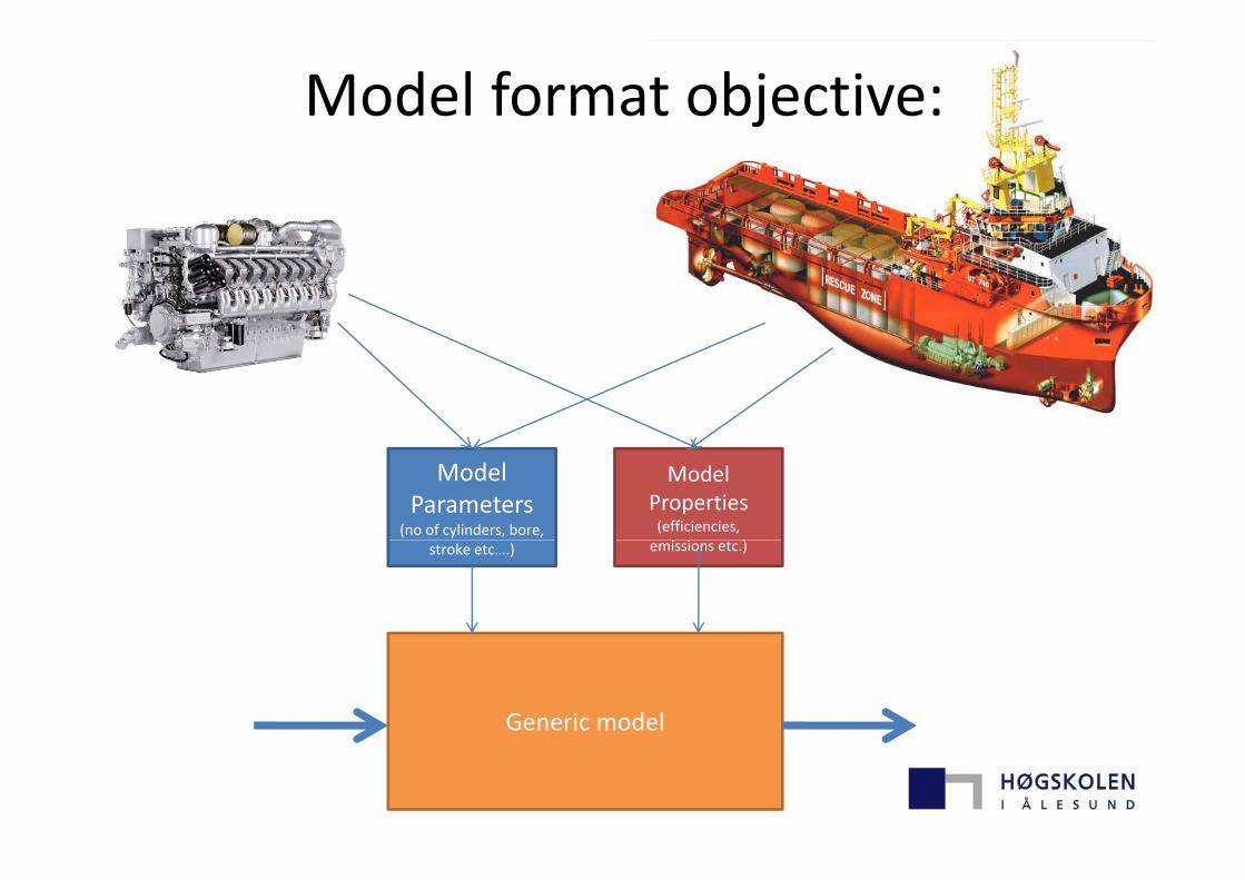
Model format objective:
ModelParameters
(no of cylinders, bore,
ModelProperties(efficiencies,
)stroke etc….) emissions etc.)
Generic model
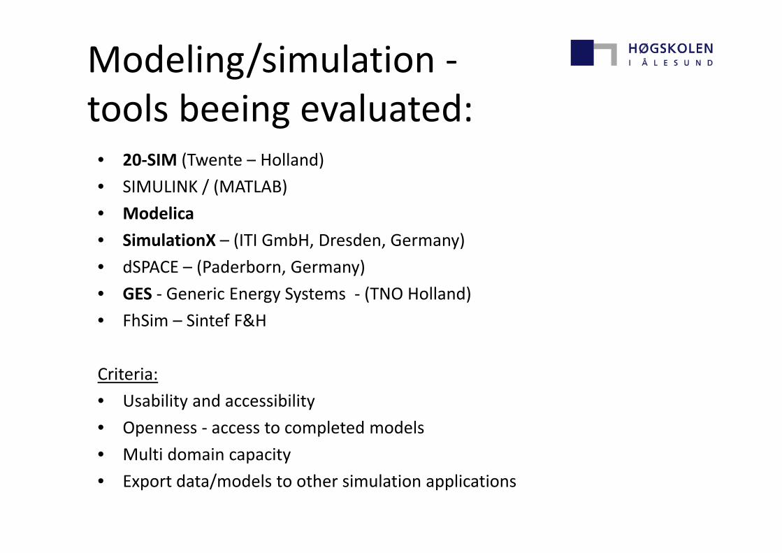
Modeling/simulation ‐tools beeing evaluated:
• 20‐SIM (Twente – Holland)
• SIMULINK / (MATLAB)
• Modelica• Modelica
• SimulationX – (ITI GmbH, Dresden, Germany)
• dSPACE – (Paderborn, Germany)
• GES ‐ Generic Energy Systems ‐ (TNO Holland)
• FhSim – Sintef F&H
Criteria:
• Usability and accessibility• Usability and accessibility
• Openness ‐ access to completed models
• Multi domain capacity
• Export data/models to other simulation applications
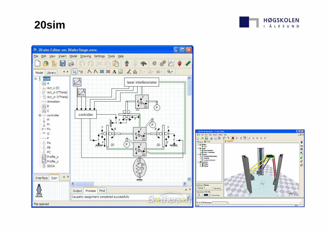
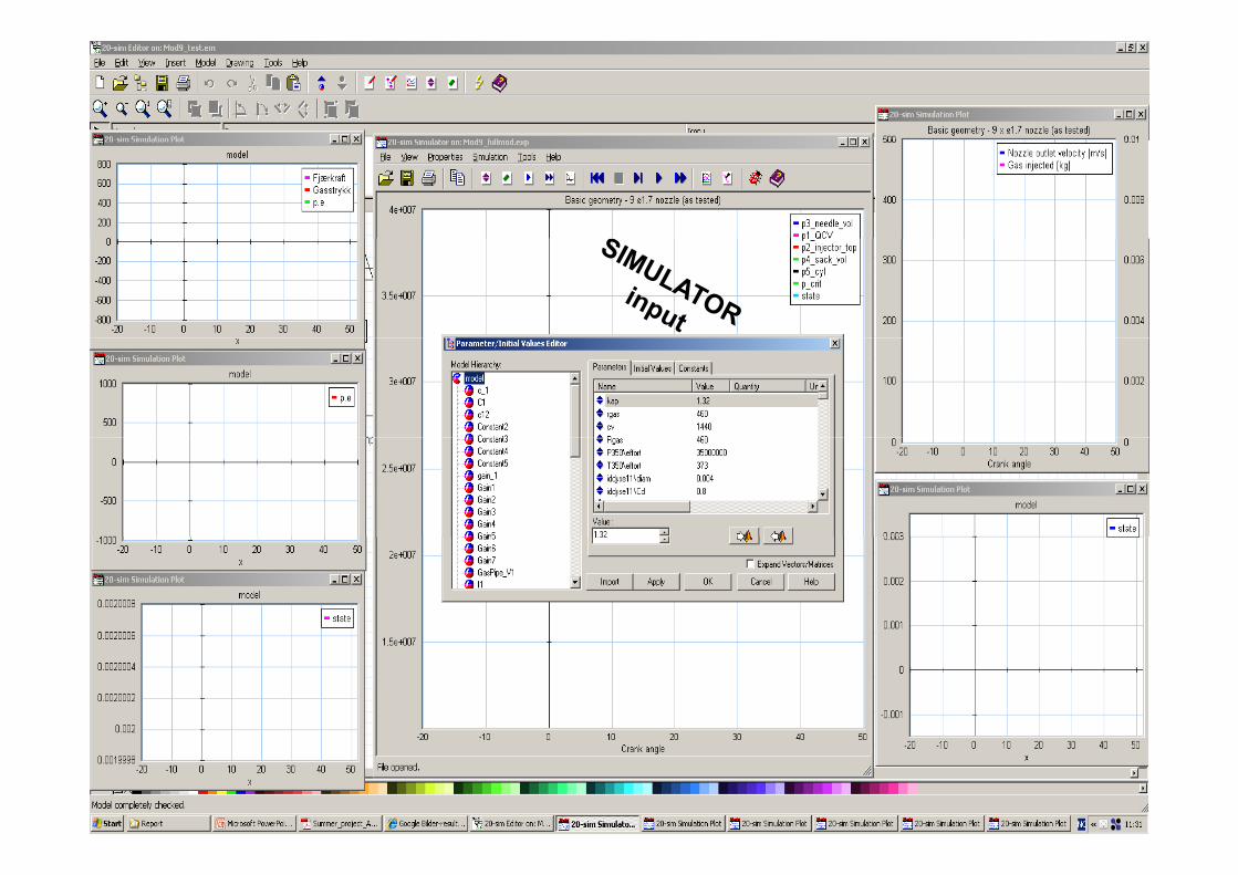
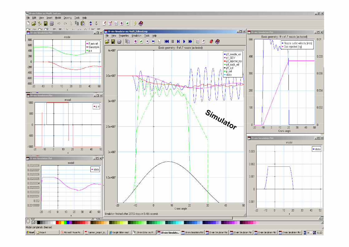
20sim
Applications:
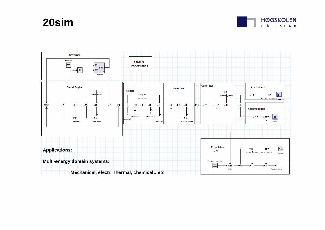
20sim
Applications:
Multi-energy domain systems:
Mechanical, electr. Thermal, chemical…etc
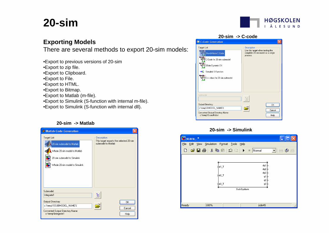
20-sim 20-sim -> C-code
Exporting ModelsThere are several methods to export 20-sim models:
•Export to previous versions of 20-sim
20 sim > C code
p p•Export to zip file.•Export to Clipboard.•Export to File.•Export to HTML.•Export to Bitmap•Export to Bitmap.•Export to Matlab (m-file).•Export to Simulink (S-function with internal m-file).•Export to Simulink (S-function with internal dll).
20-sim -> Matlab 20-sim -> Simulink
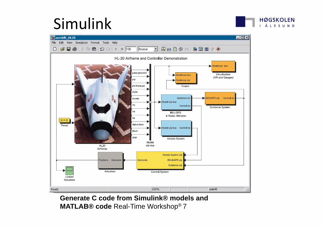
Simulink
Generate C code from Simulink® models and MATLAB® code Real-Time Workshop® 7

GES - General Energy Systems (TNO)
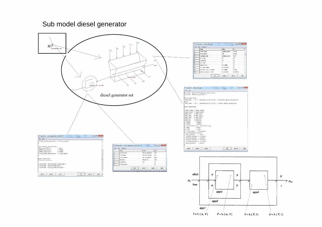
Sub model diesel generator
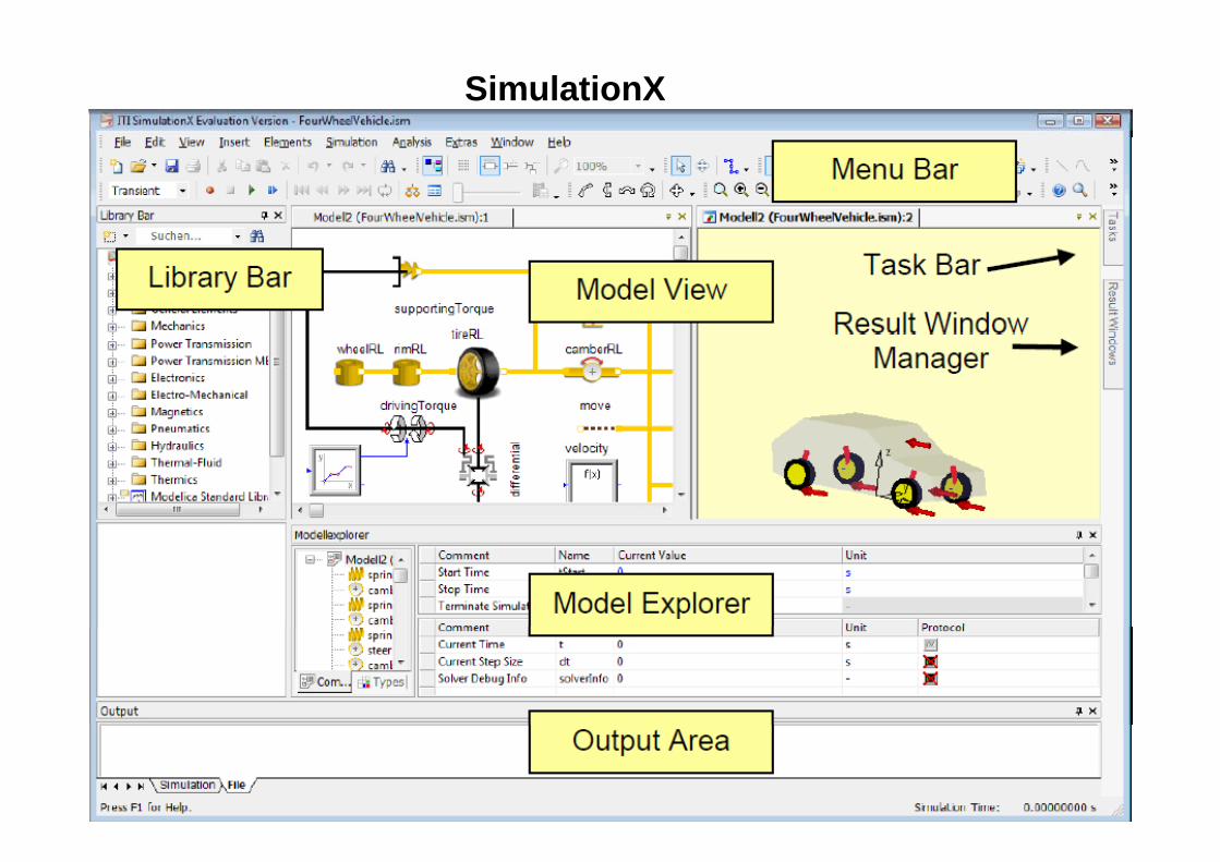
SimulationX
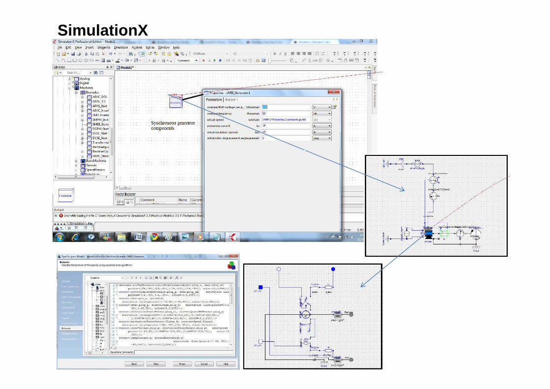
SimulationX
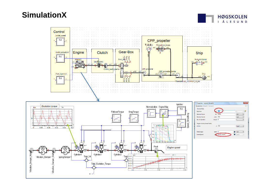
SimulationX
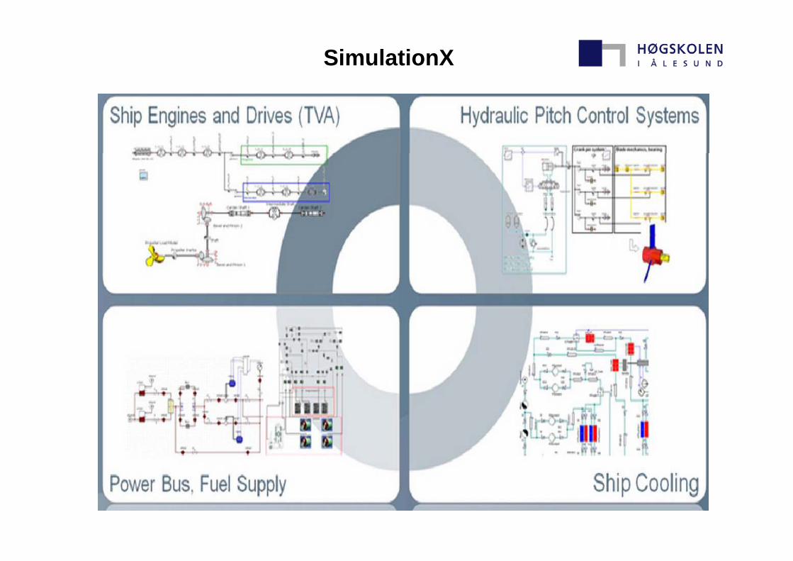
SimulationX
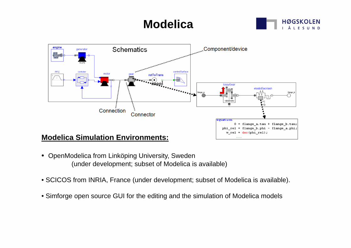
Modelica
Modelica Simulation Environments:
• OpenModelica from Linköping University, Sweden (under development; subset of Modelica is available)
• SCICOS from INRIA France (under development; subset of Modelica is available)• SCICOS from INRIA, France (under development; subset of Modelica is available).
• Simforge open source GUI for the editing and the simulation of Modelica models
Modelica
Modelica is a language for modeling of physical systems, designed to support effective library development and model exchange. It is a modern language built
l d li ith th ti l ti d bj t i t d t ton a-causal modeling with mathematical equations and object-oriented constructs to facilitate reuse of modeling knowledge.
The use of Modelica are making Modeling of the dynamic behavior of technicalThe use of Modelica are making Modeling of the dynamic behavior of technical systems consisting of components from : mechanical, electrical, thermal, hydraulic, pneumatic, fluid, control and other domains in a convenient way.
These Models are described by differential, algebraic, and discrete equations.
Commercial Modelica Simulation Environments:Commercial Modelica Simulation Environments:
-CATIA Systems from Dassault Systèmes (based on Dymola kernel with PLM integration) -Dymola from Dynasim AB, Sweden (Dynasim was acquired by Dassault Systèmes in 2006). LMS Imagine Lab AMESim from LMS International-LMS Imagine.Lab AMESim from LMS International.
-MapleSim from MapleSoft, Canada. -MathModelica from MathCore AB, Sweden.-SimulationX from ITI GmbH, Dresden, Germany.
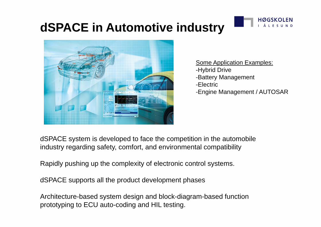
dSPACE in Automotive industry
Some Application Examples:Some Application Examples: -Hybrid Drive -Battery Management -Electric -Engine Management / AUTOSAR
dSPACE system is developed to face the competition in the automobiledSPACE system is developed to face the competition in the automobile industry regarding safety, comfort, and environmental compatibility
Rapidly pushing up the complexity of electronic control systemsRapidly pushing up the complexity of electronic control systems.
dSPACE supports all the product development phases
Architecture-based system design and block-diagram-based function prototyping to ECU auto-coding and HIL testing.
dSPACE in Aviation industry
Some Application Examples :
•Cabin Pressure Control •Turbine Controller Optimization •Real-time simulation of a complex aircraft model O ti i ti f t bi t ll d l HIL i l ti ith t bi l t i th l•Optimization of turbine controller model - HIL simulation with turbine emulator in the loop .
•Optimized algorithms for higher altitudes, speeds, lower fuel consumption and lower heat . •Real-time hardware and I/O rejection into recalculated fuel. •Noise and Vibration Reduction - reducing noise and vibrations in Helicopterg p•Electric Thrust Reverser - the first fully electric thrust reverser in commercial aviation Application
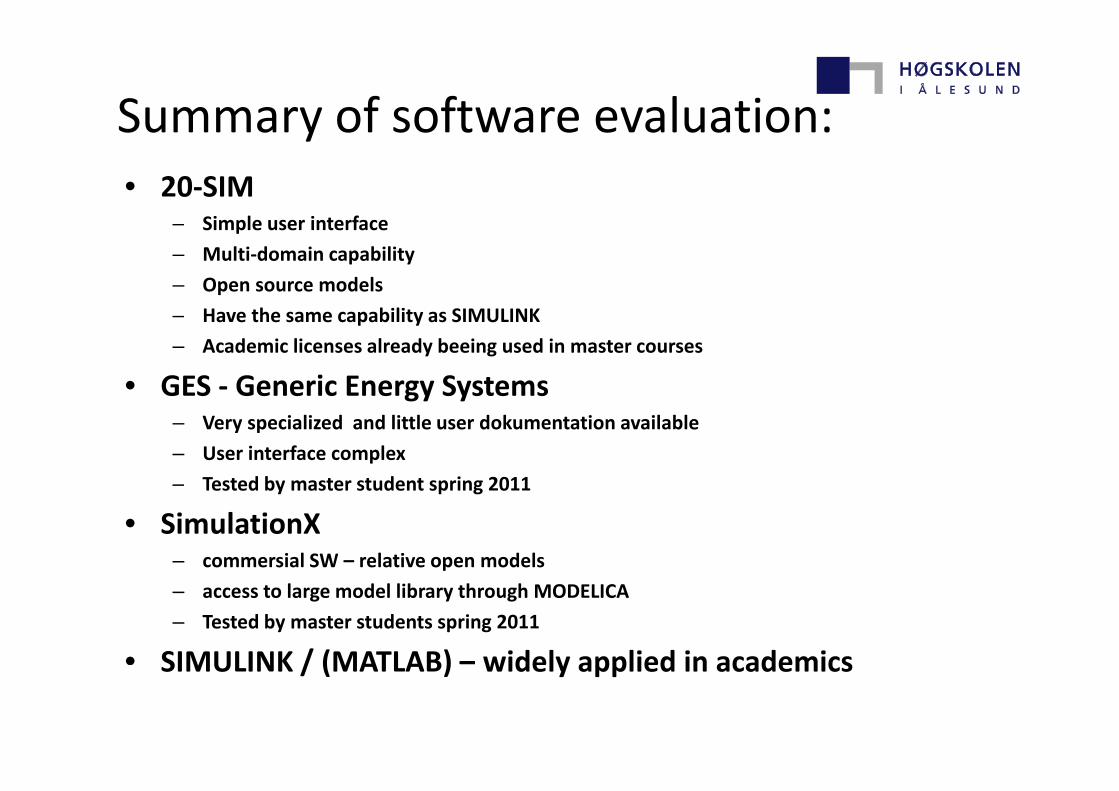
Summary of software evaluation:Summary of software evaluation:• 20‐SIM
i l i f– Simple user interface
– Multi‐domain capability
– Open source models
– Have the same capability as SIMULINK
– Academic licenses already beeing used in master courses
• GES ‐ Generic Energy SystemsGES Generic Energy Systems – Very specialized and little user dokumentation available
– User interface complex
– Tested by master student spring 2011– Tested by master student spring 2011
• SimulationX – commersial SW – relative open models
– access to large model library through MODELICA
– Tested by master students spring 2011
• SIMULINK / (MATLAB) – widely applied in academicsSIMULINK / (MATLAB) widely applied in academics
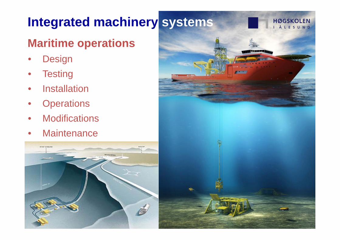
Integrated machinery systemsMaritime operations• Design• Testing• Installation• Operations• ModificationsModifications• Maintenance
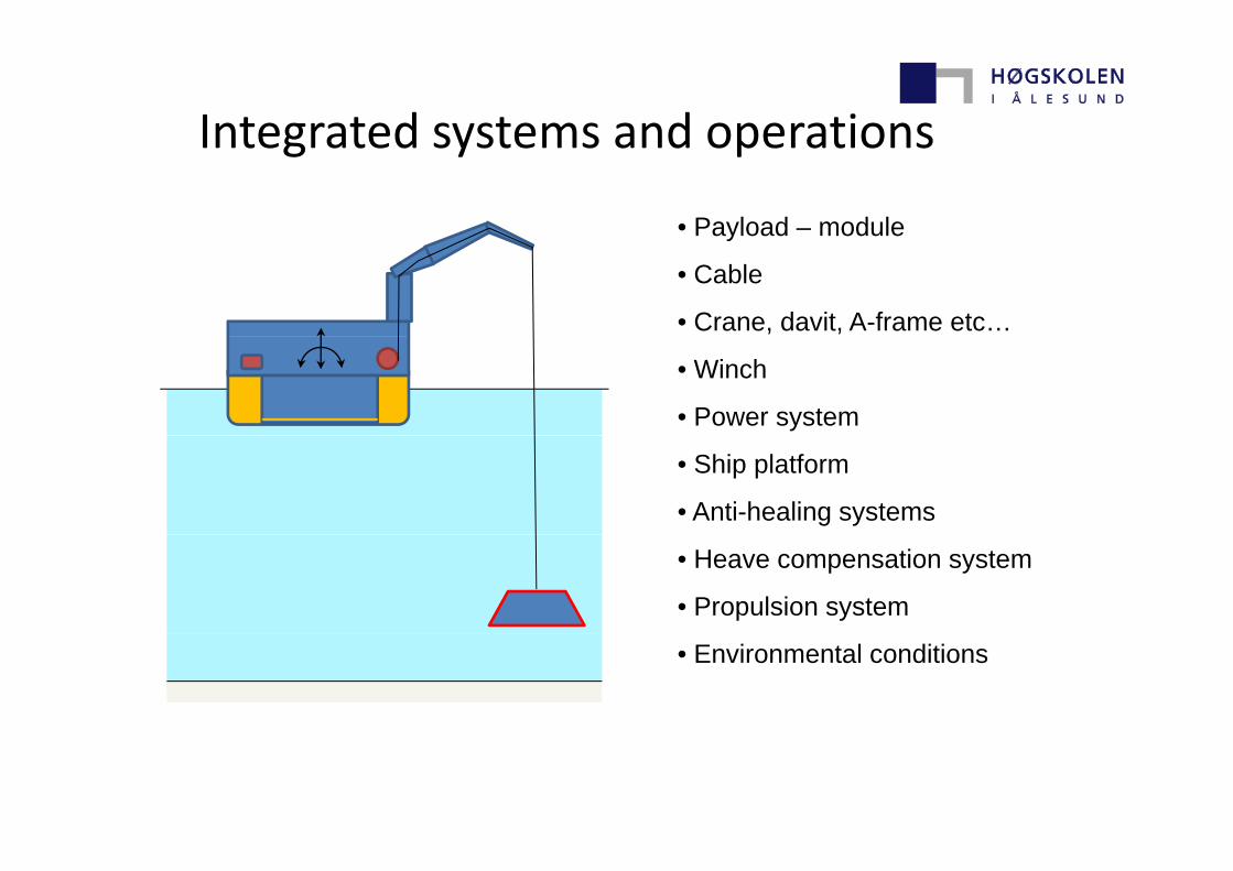
Integrated systems and operationsIntegrated systems and operations
• Payload – moduley
• Cable
• Crane, davit, A-frame etc…
• Winch
• Power system
• Ship platform
• Anti-healing systems
• Heave compensation system
• Propulsion system
• Environmental conditions
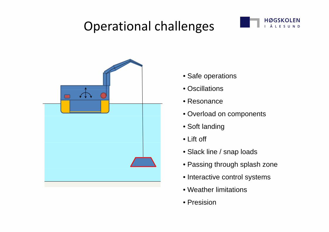
Operational challenges
• Safe operations
• OscillationsOscillations
• Resonance
• Overload on componentsOverload on components
• Soft landing
• Lift off
• Slack line / snap loads
• Passing through splash zone
• Interactive control systems
• Weather limitations
• Presision
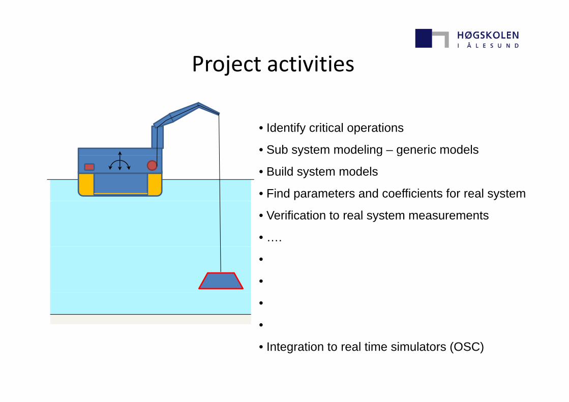
Project activitiesProject activities
• Identify critical operations
• Sub system modeling – generic modelsy g g
• Build system models
• Find parameters and coefficients for real system
• Verification to real system measurements
• ….
•
•
•
•
• Integration to real time simulators (OSC)
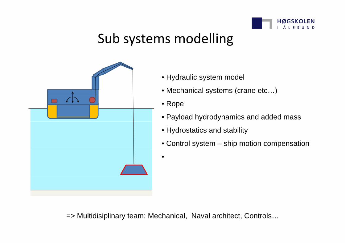
Sub systems modellingSub systems modelling
• Hydraulic system model
• Mechanical systems (crane etc…)y ( )
• Rope
• Payload hydrodynamics and added mass
• Hydrostatics and stability
• Control system – ship motion compensation
•
=> Multidisiplinary team: Mechanical, Naval architect, Controls…
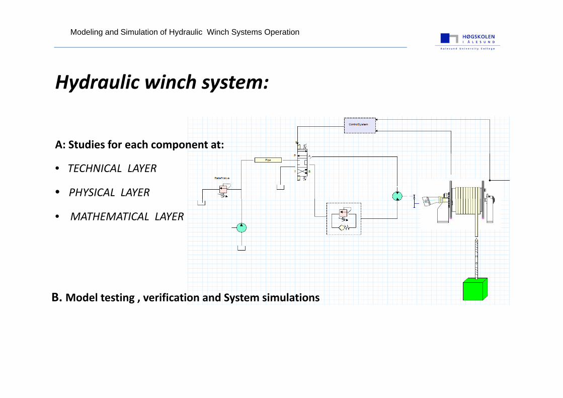
Modeling and Simulation of Hydraulic Winch Systems Operation
Hydraulic winch system:
A: Studies for each component at:
• TECHNICAL LAYER
• PHYSICAL LAYER
• MATHEMATICAL LAYER
B. Model testing , verification and System simulations

Modeling and Simulation of Hydraulic Winch Systems Operation
SYSTEM SIMULATIONHOISTING
LOWERING
Modeling and Simulation of Hydraulic Winch Systems Operation
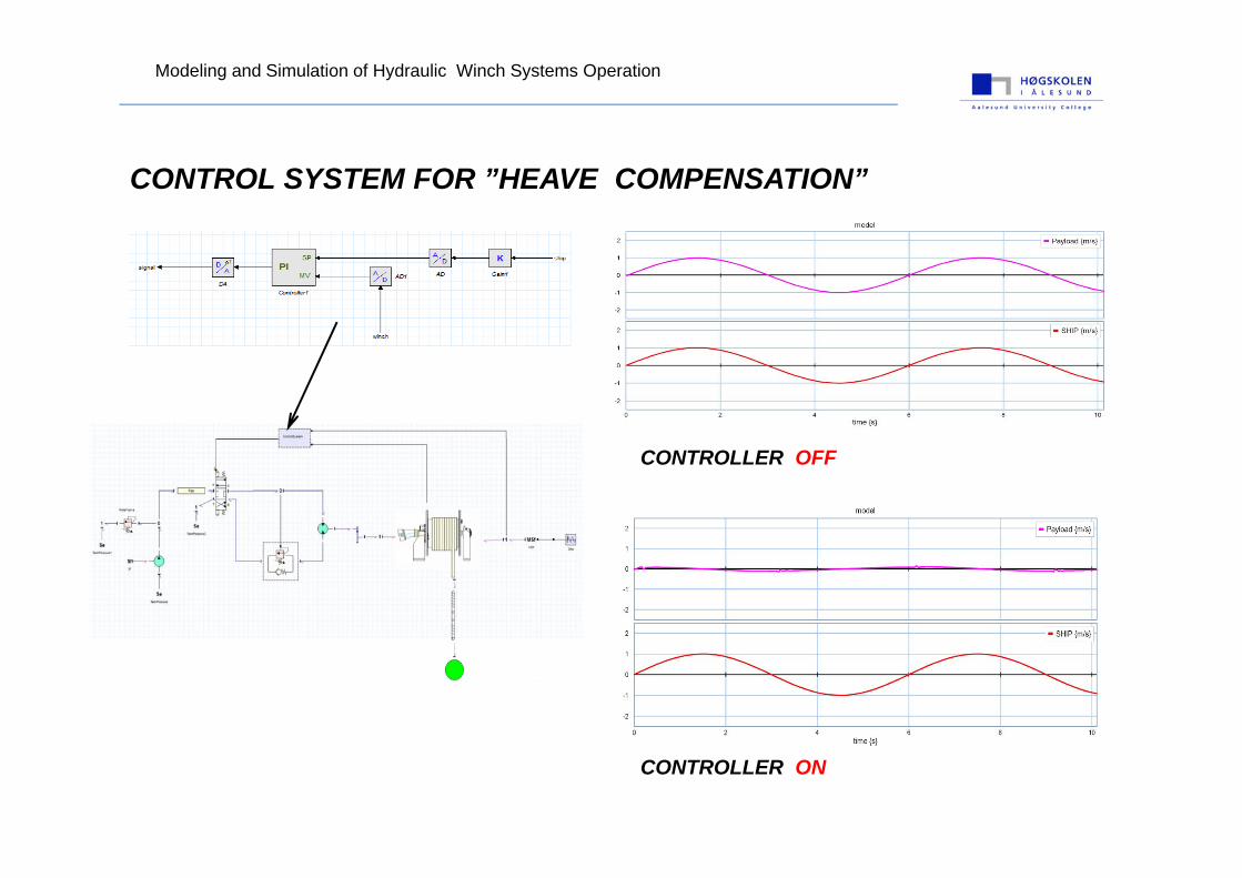
CONTROL SYSTEM FOR ”HEAVE COMPENSATION”
CONTROLLER OFF
CONTROLLER ON
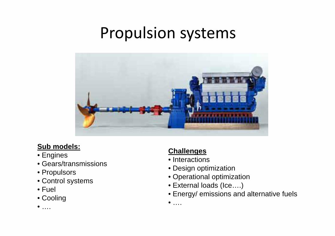
Propulsion systemsPropulsion systems
S b d lSub models:• Engines• Gears/transmissions• Propulsors
Challenges• Interactions• Design optimization• Propulsors
• Control systems• Fuel• Cooling
g p• Operational optimization• External loads (Ice….)• Energy/ emissions and alternative fuels• Cooling
• …. • ….
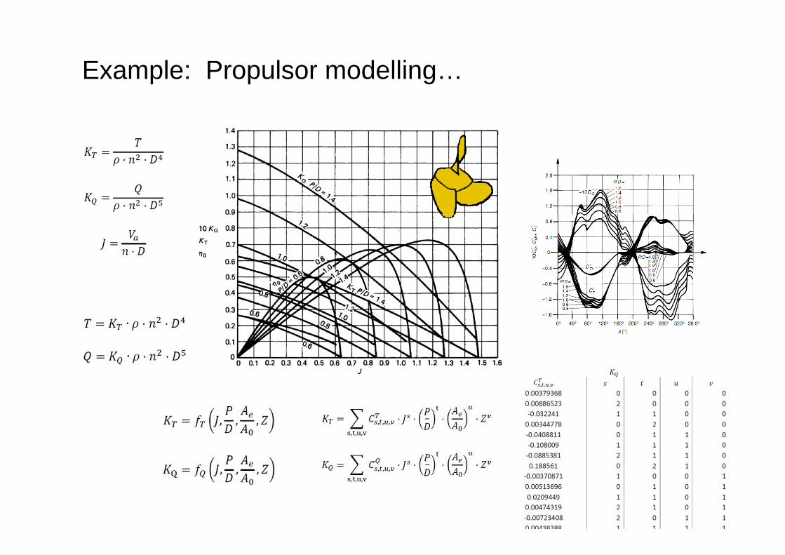
Example: Propulsor modelling…
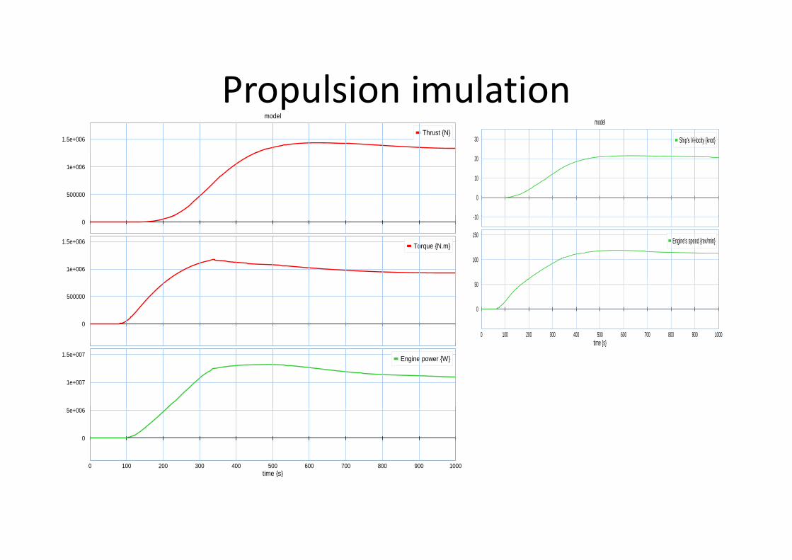
Propulsion imulationPropulsion imulationmodel
1.5e+006Thrust {N}
model
30 Ship's Velocity {knot}
500000
1e+006
10
0
10
20
0
1e+006
1.5e+006 Torque {N.m}
-10
100
150Engine's speed {rev/min}
0
500000
0 100 200 300 400 500 600 700 800 900 1000time {s}
0
50
1e+007
1.5e+007 Engine power {W}
time {s}
0 100 200 300 400 500 600 700 800 900 1000i { }
0
5e+006
time {s}
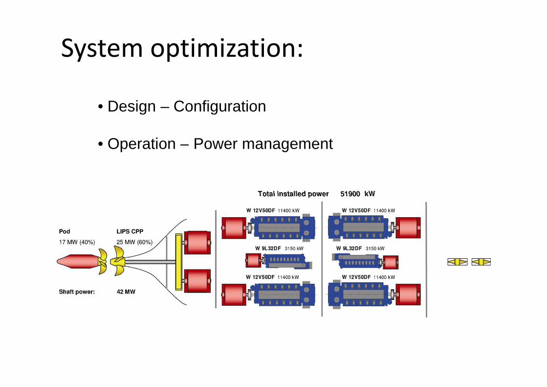
System optimization:y p
• Design Configuration• Design – Configuration
• Operation – Power managementp g
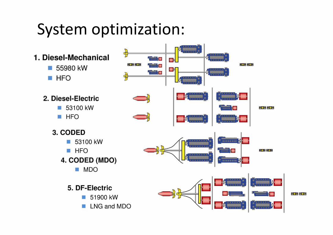
System optimization:y p
• Design Configuration• Design – Configuration
• Operation – Power managementp g
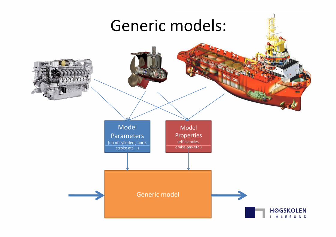
Generic models:
ModelParameters
(no of cylinders, bore,
ModelProperties(efficiencies,
)stroke etc….) emissions etc.)
Generic model


