Ii
i
NASA-CR-197156 r
NASw-4435
_,!_, - -- ! E
NASA/USRA _ _/3 _-'-University Advanced Design Program _- /_
Integral Habitat Transport System
Group://
Bill ElliottScott FrazerJoey HiggsJason Huff
Tigree Milam
_IME 4192 ..........'....."March 8, 1994 '_
oF_ _rr_
t_
_1 ul _'_
I _. _0u_ _J P'JO_ ¢ Oz _ o
t--
t-
_N_4
..J
c9_ku_t-- t/_2r_
,.-- UE_0Wu_ t.-e.4 I./'1e'- >-
I I,"
I G.
ZC_
https://ntrs.nasa.gov/search.jsp?R=19950006216 2020-02-18T08:42:25+00:00Z
Introduction
In the 1993 Fall quarter, the ME 4182 design class was sponsored to studyvarious scenarios that needed to be studied for Martian travel. The class was
sponsored by NASA and there were several different design projects. The
design that group three chose was an integral transport system for a Martian
habitat. An integral transport system means the design had to be one that was
attached to the habitat. There were several criteria that the design had to
meet. Group three performed an in depth study of the Martian environment
and looked at several different design ideas. The concept group three
developed involved the use of kinematic linkages and the use of Martian
gravity to move the habitat. The various design concepts, the criteria
matrices and all other aspects that helped group three develop their design
can be found in their 1993 ME 4182 design report.
Now it is Winter quarter 1994 and group three is faced with another problem.
The problem is building a working prototype of their Fail design. The
limitations this quarter were the parts. The group had to make the prototype
work with existing manufactured parts or make the parts themselves in a
machine shop. The prototype was scaled down roughly about twelve times
smaller than the original design. The following report describes the actions
taken by group three to build a working model.
Outline of Operations
The habitat will move by kinematic actuation of legs mounted on the end ofthe habitat. On each end of the habitat there are three leg linkages with each
set having four legs. Each set of legs are actuated independently. There are
three legs in contact with the ground at all times. The legs are located 30
degrees apart. To move the habitat, the leg located opposite to the direction of
travel actuates out causing the habitat to pivot about the center leg. Once the
habitat pivots passed the center of gravity the habitat rolls over by gravity
onto another leg which will actuate down. To turn the habitat, the side
opposite to the desired turn needs to be actuated while the other side is not.
For example, to turn left the habitat needs to be actuated on the right-hand
side. For a more detailed description of the operations refer to the 1993 Fall
quarter ME 4182 group three design report.

¢
Overview of Model's Parts:
Four Leg Linkages:Material: Aluminum U-shaped beams
Lengths: Long = 25.54 inchesShort ffi 13.4 inches
Joints: 5/16" x 2" bolts, tapped with 8-32 screw thread
1/2" OD x 5/8" long x 3/8" ID nylon spacers
3/4" OD x 13/64" long x .385" ID nylon spacers
Rivets
t Habitat:
Material: Sheet Metal
Length: 3 feetDiameter: 16 inches
Actuator:
Rod died with 2 inches of 8-32 screw stock
Motor: Johnson Electric #3202 144233-01Gears: Black & Decker Automatic Screwdriver
Disks:
Material: Plexiglas
Outside Diameter: 10 inches
Slot Length: 1 1/2"

General Assembly
Shown below is a sketch of the assembly pattern for the integral transport
system. The length shown represent the distances from the edge of thehabitat to the center of the motor or the center of the actuation rod.
12.7875 inches _[
6.3 inches _
inches
iiii!!!ili L_g Spacer
,, _ Leg Linkage
I] 10.3375 inches _=
Suppo_

Habitat
The prototype is made of 16 inch sheet metal pipe. The end caps are cut out of
14 gauge sheet metal and machined to get the pipe (Material courtesy of
Searcy Heating & Air Thomasville, GA). The end caps are attached by sheetmetal screws.
Four Leg Linkages
The leg length were found using the proportions between the two habitat
diameters. The design of the Integral Habitat Transport System (Appendix)
was based on a habitat diameter of 5 meters. Using a diameter of 18 inches for
the model, the leg lengths are found using the following equations.
L 18 inches
3.72meters 5meters
L = 13.4 inches
Z
3.5meters
18 inches
5 meters
z = 3.5 inches
X
3.2meters
18inches
5meters
x = 11.52 inches
The long leg length = 2x + z = 26.54 inches
The short leg length = 11.52 inches
Aluminum U-shaped beams were used to build the leg linkages.
The legs were joined using rivets with a nylon spacer between each leg.
Bolts (5/16" x 2 ") and nylon spacers joined the legs at the actuation points.
Leg Spacers
Spacers were used to separate the leg ankages while allowing room for the
gear sets. The length of the spacers was determined by measuring the distance
from the center of the gear at the motor to the center of the actuation rod. By
setting that distance equal to half the spacer length plus the width of a disk, a
leg, and half of a nylon spacer, the length of the spacer is found. The length of
the three spacers were as follows:

First spacer -- 2.475 inchesMiddle spacer -- 2.7 inchesLast spacer = 2.775 inches
The leg spacers were made of a Plexiglas type tube with an inner diameter of 2inches. The inner diameter of the spacer was the same as the outer diameter
of the support pole. This provided a secure fit between the two tubes.
Support Pole
The support pole was used to house the gear sets and to place the leg linkagesand disks. The pole is made of a Plexiglas type tube with an outer diameter of2 inches and an inner diameter of 1.75 inches. The Plexiglas type tube waschosen because it had the desired inner and outer diameters, not because of its
material properties. The pole had a total length of 6 feet. The pole ranthrough the habitat and out the end to support the leg linkages. Holes weredrilled and slots were milled out to allow room for the motor and
screw/actuator.
Disc System
Discs were introduced to the design to help reduce the moment on the leg
linkages. The discs are 10 inches outside diameter and 2 inches insidediameter. The discs contain 1 1/2 inch slot positioned 180 degrees apart.
These slots allow the leg's joints to slide up and down as they move.
Gear Assembly
Gears from the Black and Decker Automatic screwdriver were utilized to
provide torque to turn the screw. In addition, two other gears were used totranslate the torque to the screw/actuator position.
Forces
In order to determine the forces present in each member of the model,
detailed force diagrams had to be completed. These force analysis calculationswere done for the worst case scenarios to ensure proper load handling
capabilities. The weight of the model was found to be 40 lbs. The first worstcase scenario is found when one leg is at its minimum distance to the ground
while supporting half of the weight of the entire system, with the load screwmounted parallel to the ground. The other worst case scenario occurs when
the model is on a 30 ° slope with one leg extended to its maximum distance,
while supporting the weight of half the model. To be a worst case scenario,this occurs while the load screw is mounted perpendicular to the centerline of

the member. Although these two scenarios would probably never occur, themodel is designed to withstand these forces as an added factor of safety.
When the load screw is mounted perpendicular to the ground and themodel has to be raised from a minimum distance, the forces in the screw will
always be 20 lb in compression because the screw is acting along the centerlineof the model. This is not a worst case scenario, because the screw is acting
along the centerline of the model. Therefore, the forces in the worst casescenarios need to be calculated, so that a torque can be determined which,
when applied to the screw, will cause the model to actuate.
For the first worst case, a normal force of 20 lb acts straight up into the
connection joining the two L legs together. This force is then translated intothe two legs to give the force equivalents. Due to the two legs being
symmetric about the normal force, the force equivalents are equal in both
legs.
F1= 20 lb / [2sin(90-p/2)]
F1 -- 20 lb / [2sin(36.15)]
F1 = 16.95 lb Compression
Now, the forces in the two X legs can be calculated. Once again, the two
angles are equivalent, therefore the two new force equivalents will also be thesame.
F2= F1 / cos(a)
F2 = 16.95 lb / cos(54.585°)
F2 - 29.25 Ib Compression
At the junction of the two X legs and the two Z legs, the four legs meet
symmetrically. This means that the forces present in the X legs equals thosefound in the Z legs. The next connection corresponds to the junction wherethe load screw is connected to the Z legs. Seeing as how the load screw sits
symmetrically within the design at this time, the force equivalents in thescrew can be easily found.
F_ = F2* cos(¢/2)
Fs = 29.25 lb * cos(18.435 °)
4F. = 2Y3tMIt T_nsion

For the other worst case scenario; while on a 30 ° slope, a force of 20 lb
acts at an angle of 30 ° upon the connection between the two L legs in the
direction of gravity. The 20 Ib force translates onto the 30 ° slope with a Y
component and an X component, which then translate into the L legs.
Y = 20 lb * sin(60 °)
Y -- 17.322 lb
X - 20 lb * sin(30*)
X=101b
By summing the forces in the X and Y directions, the force equivalents
can be determined in the L legs. The upper leg will be designated as F 1 and
the lower leg as F 2.
XFy = 17.322 lb = F2 * sin(30 - 0/2) + F 1 * sin(30 + 0/2)
_Fy = 17.322 lb = F 2 * sin(14.389) + F 1 * sin(45.611)
,_,Fx = 10 lb = F 2 * cos(30 - 0/2) + F 1 * cos(30 + 0/2)
,_,Fy = 10 lb = F 2 * cos(14.389) + F 1 * cos(45.611)
Solve for F2:
F 2 = [10 lb - F 1 * cos(45.611)] / cos(14.389)
By substitution:
17.322 lb = [10 lb - F 1 * cos(45.611)] * tan(14.389) + F 1 * sin(45.611)
F 1 = 27.575 Ib Compression
F 2 -- 9.$903 Ib Tension
Now, the forces in the two X legs can be calculated. The upper X leg
shall be designated as F 3 and the lower as F 4.
F 3 = F 1 / cos(180 - z)
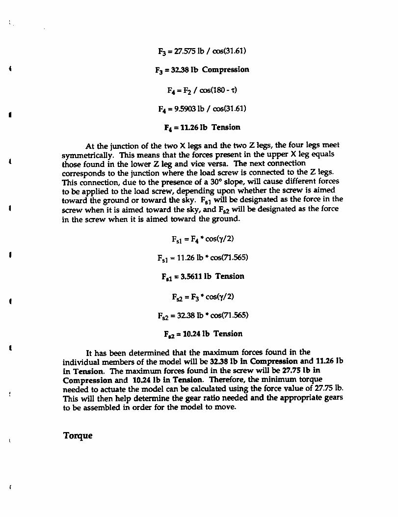
F 3 - 27.575 lb / cos(31.61)
Fa -- 32.38 Ib Compression
F4= F2/ cos080-_)
F4 = 9.5903 lb / cos(31.61)
F4 --"11.26 lb Tension
At the junction of the two X legs and the two Z legs, the four legs meet
symmetrically. This means that the forces present in the upper X leg equals
those found in the lower Z leg and vice versa. The next connection
corresponds to the junction where the load screw is connected to the Z legs.
This connection, due to the presence of a 30 ° slope, will cause different forces
to be applied to the load screw, depending upon whether the screw is aimed
toward the ground or toward the sky. Fsl will be designated as the force in the
screw when it is aimed toward the sky, and Fs2 will be designated as the force
in the screw when it is aimed toward the ground.
Fsl = F4* cos(_//2)
Fsl = 11.26 Ib * cos(TI.565)
Fsl = 3.5611 lb Tension
Fa = F3 *cos(,//2)
Fs2 = 32.38 lb * cos(71.565)
Fs2 = 10.24 Ib Tension
It has been determined that the maximum forces found in the
individual members of the model will be 32.38 lb in Compression and 11.26 lb
in Tension. The maximum forces found in the screw will be 27.75 lb in
Compression and 10.24 lb in Tension. Therefore, the minimum torque
needed to actuate the model can be calculated using the force value of 27.75 lb.
This will then help determine the gear ratio needed and the appropriate gearsto be assembled in order for the model to move.
Torque
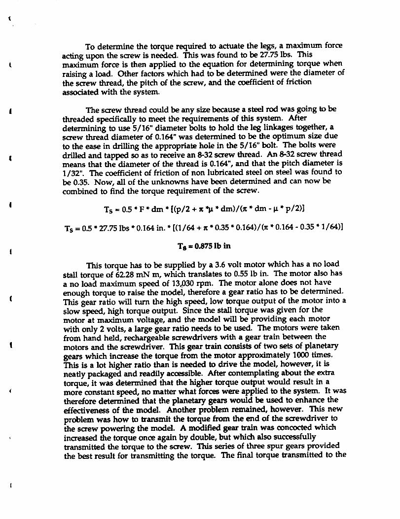
To determine the torque required to actuate the legs, a maximum force
acting upon the screw is needed. This was found to be 27.75 lbs. This
maximum force is then applied to the equation for determining torque when
raising a load. Other factors which had to be determined were the diameter of
the screw thread, the pitch of the screw, and the coefficient of friction
associated with the system.
The screw thread could be any size because a steel rod was going to be
threaded specifically to meet the requirements of this system. After
determining to use 5/16" diameter bolts to hold the leg linkages together, a
screw thread diameter of 0.164" was determined to be the optimum size due
to the ease in drilling the appropriate hole in the 5/16" bolt. The bolts were
drilled and tapped so as to receive an 8-32 screw thread. An 8-32 screw threadmeans that the diameter of the thread is 0.164", and that the pitch diameter is
1/32". The coefficient of friction of non lubricated steel on steel was found to
be 0.35. Now, all of the unknowns have been determined and can now be
combined to find the torque requirement of the screw.
Ts = 0.5 * F *dm * [(p/2 + x *]_ * dm)/(_ *dm - _ * p/2)]
"Is -- 0.5 * 27.75 lbs * 0.164 in. * [(1/64 + x * 0.35 * 0.164)/0r * 0.164 - 0.35 * 1/64)]
TS = 0.875 Ib in
This torque has to be supplied by a 3.6 volt motor which has a no load
stall torque of 62.28 mN m, which translates to 0.55 lb in. The motor also has
a no load maximum speed of 13,030 rpm. The motor alone does not have
enough torque to raise the model, therefore a gear ratio has to be determined.
This gear ratio will turn the high speed, low torque output of the motor into a
slow speed, high torque output. Since the stall torque was given for themotor at maximum voltage, and the model will be providing each motor
with only 2 volts, a large gear ratio needs to be used. The motors were taken
from hand held, rechargeable screwdrivers with a gear train between the
motors and the screwdriver. This gear train consists of two sets of planetary
gears which increase the torque from the motor approximately 1000 times.
This is a lot higher ratio than is needed to drive the model, however, it is
neatly packaged and readily accessible. After contemplating about the extra
torque, it was determined that the higher torque output would result in a
more constant speed, no matter what forces were applied to the system. It was
therefore determined that the planetary gears would be used to enhance the
effectiveness of the model. Another problem remained, however. This new
problem was how to transmit the torque from the end of the screwdriver to
the screw powering the model. A modified gear train was concocted which
increased the torque once again by double, but which also successfully
transmitted the torque to the screw. This series of three spur gears provided
the best result for transmitting the torque. The final torque transmitted to the

screw is approximately equal to 90 ft lbs. This guarantees that the system will
not experience any serious fluctuations in speed while being actuated.