
Industrivej 3-9 DK-9460 Brovst
Tel.: +45 98 23 60 88 Fax:+45 98 23 61 44
25.01.16
Instructions for Use of
Centerless Belt Grinder
Model CGC 75

1
EU declaration of conformity
hereby declares that
SCANTOOL Centerless Belt Grinder Model CGC 75 is manufactured in accordance with the provisions of the Council Directive of May 17, 2006 (2006/42/EF)
And is in accordance with:
Council Directive of February 19, 1973 (73/23/EEC) - Low Voltage Directive - with subsequent amendments (Housing Ministry order no. 797 of August 30, 1994)
Council Directive of May 3, 1989 (89/336/EEC) - Low Voltage Directive - with subsequent amendments (Telecom Agency's EMC order no. 796 of December 5, 1991 with subsequent changes)
Genvex A/S Industrivej 3-9 9460 Brovst Denmark Website: www.scantool-group.com Tel.: +45 98 23 60 88 Fax.: +45 98 23 61 44
2
Contents
1.0 TRANSPORT 3
1.1 TRANSPORT 3 1.2 PARTS OF THE MACHINE 4
2.0 PREPARATION 5
2.1 ASSEMBLY 5
3.0 OPERATION 8
3.1 SELECTION OF SUPPORT 8 3.2 SETTING THE FORK 9 3.3 PUTTING THE ARTICLE IN THE MACHINE 9 3.4 LOCATION OF DISTANCE STOP 10 3.5 SELECTION OF SPEED OF BELT GRINDER 11 3.6 FEED SPEED AND DIRECTION 11 3.7 OPERATION OF THE CENTERLESS JIG 12 3.10 SAFETY RULES FOR STATIONARY POWER TOOLS. 12
4.0 SPARE PARTS 15
4.1 CENTERLESS GRINDING JIG (CGC) 15 4.2 BELT GRINDER WITHOUT EXHAUST 17 4.3 OPTIONAL EQUIPMENT 18
5.0 TECHNICAL DATA 19
5.1 SPECIFICATIONS 19 5.2 ELECTRICAL DIAGRAM 20 5.3 GARANTEE 20

3
1.0 Transport
1.1 Transport
The centerless grinding jig is delivered on a pallet of size 120cm x 80cm (48x32 inch).
On the pallet there are (see diagram 1.1):
1. A belt grinder (A) 2. Base (E) (without right tray) with centerless jig and support roller. 3. Right tray (F) 4. 2 Curtains 5. 3 Curtain rods 6. Teflon support plate 7. 2 screws M10x20 w/ corresponding auto-washers.
4
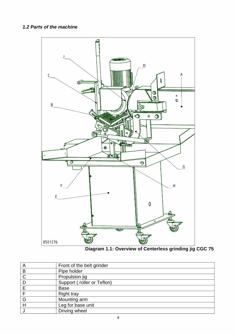
1.2 Parts of the machine
Diagram 1.1: Overview of Centerless grinding jig CGC 75
A Front of the belt grinder
B Pipe holder
C Propulsion jig
D Support ( roller or Teflon)
E Base
F Right tray
G Mounting arm
H Leg for base unit
J Driving wheel

5
2.0 Preparation
2.1 Assembly
Assemble the received parts as follows. (See diagram 1.1)
1. Install the right tray on the base. 2. Tilt the motor up in the vertical position and tighten legs to the base frame (H). 3. Place the curtain rods in the trays together and hang the curtains up (see diagram
2.1).
Diagram 2.1: Assembly of curtains and curtain rods.
4. Fasten the belt grinder to the floor. 5. Roll the base under the front edge of the belt grinder.
6
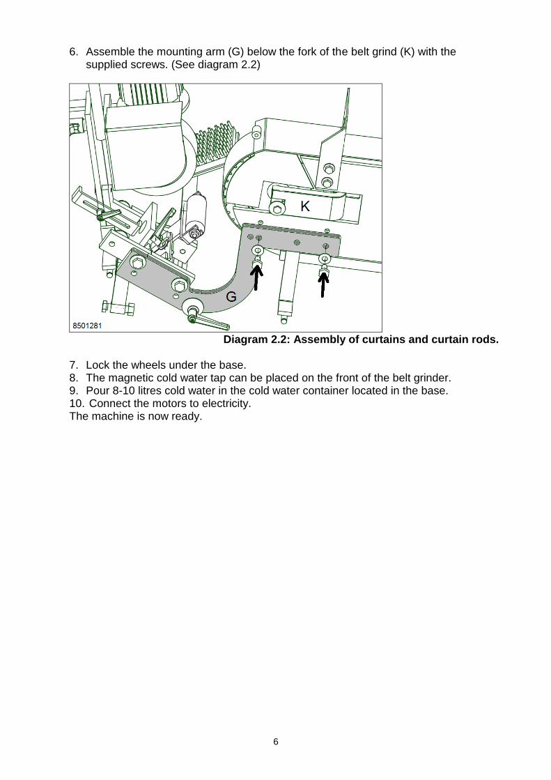
6. Assemble the mounting arm (G) below the fork of the belt grind (K) with the
supplied screws. (See diagram 2.2)
Diagram 2.2: Assembly of curtains and curtain rods.
7. Lock the wheels under the base. 8. The magnetic cold water tap can be placed on the front of the belt grinder. 9. Pour 8-10 litres cold water in the cold water container located in the base. 10. Connect the motors to electricity. The machine is now ready.
7
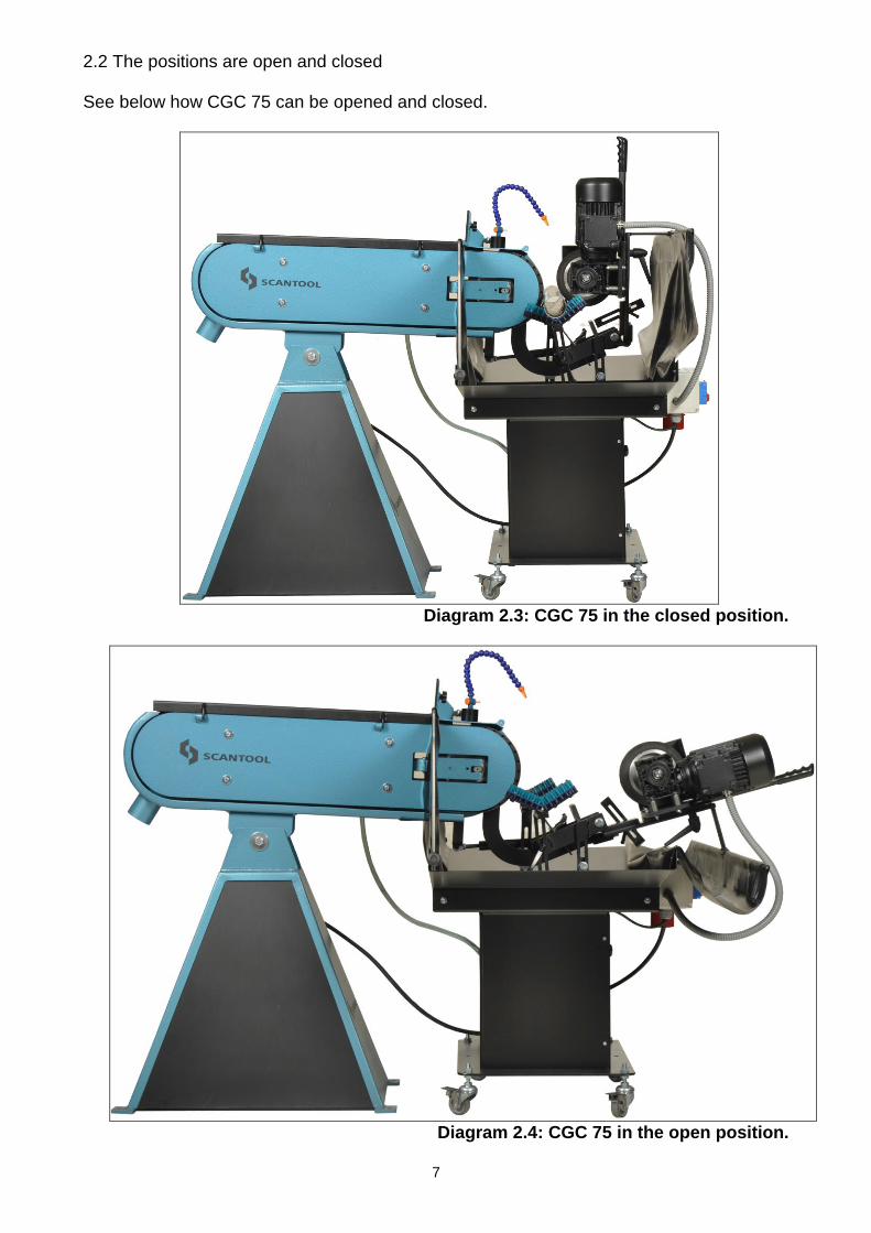
2.2 The positions are open and closed See below how CGC 75 can be opened and closed.
Diagram 2.3: CGC 75 in the closed position.
Diagram 2.4: CGC 75 in the open position.
8
3.0 Operation
The machine must be adjusted again for each tube dimension. Then the feed rate and direction are set.
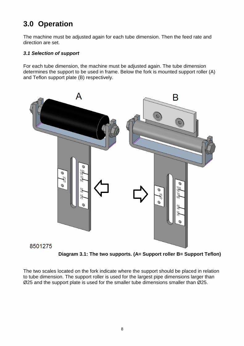
3.1 Selection of support
For each tube dimension, the machine must be adjusted again. The tube dimension determines the support to be used in frame. Below the fork is mounted support roller (A) and Teflon support plate (B) respectively.
Diagram 3.1: The two supports. (A= Support roller B= Support Teflon)
The two scales located on the fork indicate where the support should be placed in relation to tube dimension. The support roller is used for the largest pipe dimensions larger than Ø25 and the support plate is used for the smaller tube dimensions smaller than Ø25.
Support table

9
3.2 Setting the fork
The fork height is set depending on the tube dimension Ø(inch). Loosen the lever and move the fork to the tube dimension, which is to be processed. The scale on the left is used with the help of the support Teflon. The scale to the right is used with the help of the support roller as seen below.
Diagram 3.2: The fork can slide up and down on the scales.
3.3 Putting the article in the machine
Place the article in the machine. Pull the propulsion jig to the open position (see diagram 2.4). Place the tube in the machine and adjust the pipe clamps so that they support it. Close the machine.
Remember for safety It is important to emphasize that when the tube is running, there is a chance that it can jump out of position. See diagram 3.3. For this reason, remember that the centre of the tube should never come past the centre of the support roller.
Diagram 3.3: Centre of centre for safety

10
3.4 Location of distance stop
The drive wheel should NEVER come in contact with the sanding belt. The distance stop is a safety precaution so that this can be avoided. For each pip dimension the distance stop must be adjusted, in order to avoid that the propulsion jig tilts down and comes in contact with the sanding belt. See the explanation in diagram 3.4. Here, the distance stop(1) is moved almost down to the plate(2). The distance stop between (1) and (2) must be 2-5 mm/0.1-0.2 inch - never less than 2 mm/0.1 inch.
Diagram 3.4: Direction of rotation of the drive gear (Q), Article (R) and Sanding belt
(S).
11
3.5 Selection of speed of belt grinder
The belt grinder is a two-speed belt grinder.
High speed is used for cleaning the pipes together with 60-80 grit sanding belts.
Low speed is used for finishing and polishing. After cleaning the pipes, a 180-400 grit sanding belt is used for finishing. The last process is polishing and here a 600-1200 grit sanding belt is used. Note that optimal polishing is achieved using as light a pressure as possible with the drive wheel. This applies especially during the final polishing stage.
Scantool Group offers a starter pack of the above sanding belts in grades adapted
to the processes: cleaning, finishing and polishing. Upon delivery, the standard
sanding belt is VSM K180 on the belt grinder. Please contact us for further
information. Now place the pipe between drive wheels, support and the contact wheel of the belt grinder with the sanding belt. Adjust the pipe clamps so that they support the pipe on both sides of the machine. The two motors on the belt grinder and propulsion unit can now be started at the desired speed. Start in the middle of the pipe to see the result of the set-up.
3.6 Feed speed and direction
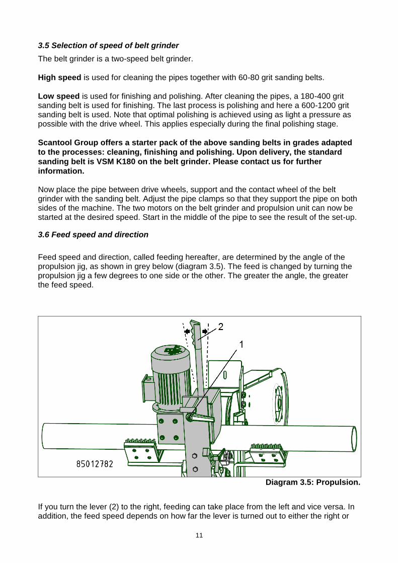
Feed speed and direction, called feeding hereafter, are determined by the angle of the propulsion jig, as shown in grey below (diagram 3.5). The feed is changed by turning the propulsion jig a few degrees to one side or the other. The greater the angle, the greater the feed speed.
Diagram 3.5: Propulsion.
If you turn the lever (2) to the right, feeding can take place from the left and vice versa. In addition, the feed speed depends on how far the lever is turned out to either the right or
12
left side. Angles around 3-5 degrees will be sufficient for a good feed speed. It is necessary to experiment for each type of article. Turn off the machine and loosen the lever (1) on the front section to move the lever (2). Tighten lever 1 again and see how the machine runs now.
3.7 Operation of the centerless jig
1. Start the belt grinder and the centerless jig. If cooling is desired, open the cooling liquid tap a little bit and adjust the hose down against the sanding area. (Note that cooling must be turned off when the machine is not running for the sake of the sanding belt)
2. Check that the drive wheel on the Centerless jig is running in the direction of the
arrow. There is an arrow on the jig, which shows the correct direction corresponding to the arrow in diagram 3.4.
3. Carefully place the article in front of the rotating sanding belt and slowly lead the
centerless jig down against the article, which will rotate in the opposite direction of the drive wheel on the jig. Feed speed and direction are adjusted by turning the drive part to the right or left. See section 3.7.
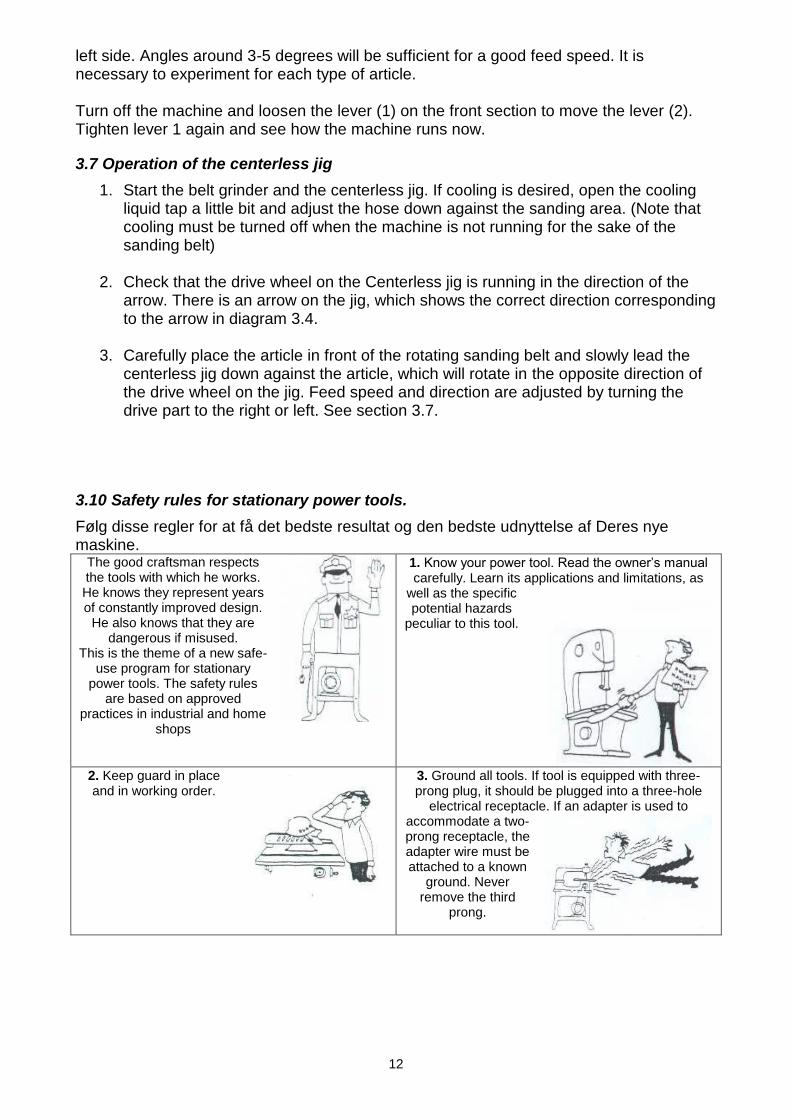
3.10 Safety rules for stationary power tools.
Følg disse regler for at få det bedste resultat og den bedste udnyttelse af Deres nye maskine.
The good craftsman respects the tools with which he works. He knows they represent years of constantly improved design.
He also knows that they are dangerous if misused.
This is the theme of a new safe-use program for stationary
power tools. The safety rules are based on approved
practices in industrial and home shops
1. Know your power tool. Read the owner’s manual carefully. Learn its applications and limitations, as
well as the specific potential hazards
peculiar to this tool.
2. Keep guard in place and in working order.
3. Ground all tools. If tool is equipped with three-prong plug, it should be plugged into a three-hole
electrical receptacle. If an adapter is used to accommodate a two-prong receptacle, the adapter wire must be attached to a known
ground. Never remove the third
prong.

13
4. Remove adjusting keys and wrenches. Form
habit of checking to see that keys and adjusting wrenches is removed before turning it on.
5. Cluttered areas and benches invite accidents.
6. Avoid dangerous environment. Don’t use
power tools in damp or wet locations or expose them to rain. Keep your work area
well lighted.
6. Keep children away. All visitors should be kept in a safe distance from work area.
8. Make workshop kid proof with padlocks, master switches, or by removing starter keys.
9. Don’t force tool. It will do the job better and be safer at the rate for which it was designed.
.
10. Use right tool. Don’t force tool or attachment to do a job it was not designed for.
11. Wear proper apparel. Wear no loose clothing, gloves, neckties, rings,
bracelets, or other jewellery which may get caught in moving parts.
Non-slip footwear is recommended. Wear
protective hair covering to contain long hair.
12. Always use safety glasses. Also use face or dust mask if cutting operation is dusty. Everyday eyeglasses only have impact resistant
lenses. They are NOT safety glasses.
13. Secure works. Use clamps or vise to hold works, when practical. It’s safer than using your hands and it frees both hands to operate tool.
14. Don’t overreach.
Keep proper footing and balance at all times.
15. Maintain tools with care. Keep tools sharp and clean for best and safest performance. Follow instructions for lubricating and changing accessories.

14
16. Disconnect tools before servicing and when changing accessories such as grinding wheels, polishing mops, grinding belts, blades, bits, cutters, etc.
17. Reduce the risk of unintentional starting. Make sure switch is in off position before plugging in.
18. Use recommended accessories. Consult owner’s manual for recommended accessories. Use of improper accessories may cause risk of injury to persons.

15
4.0 Spare parts When ordering spare parts, the production number and the serial number must be furnished. The spare parts are divided into the Centerless jig and belt grinder. Please note that there are a few parts that have been removed from belt grinder in connection with preparation for shipment of the centerless belt grinder. See section 4.3.
4.1 Centerless grinding jig (CGC)
Diagram: 4.1: Parts drawing for Centerless CGC 75

16
Spare parts list for Centerless CGC 75 Pos. Nr. Beskrivelse Antal CGC 75
1 Sokkel 1 8501122
2 Bakke højre 1 8501188
3 Bakke venstre 1 8501187
4 Frontplade 1 8501114
5 Unbracobolt M6x12 4 0120621
6 Møtrik M10 12 5438761
7 Stålsætbolt M8x12 4 0300144
8 Skive ø22xø10x1,2 4 0105132
9 Hjul m/bremse 4 0129000
10 Stålsætbolt M10x55 4 0110107
11 Afbryder Tripus-3x400V-7,5A 1 0188852
12 Forhæng foran kpl 1 8501166
13 Gardinstang for 1 8501183
14 Forhæng bag 1 8501164
15 Gardinstang bag 2 8501182
16 Ben f/grundstel 1 8501149
17 Stålsætbolt M12x45 1 0300135
18 Møtrik M12 1 0411612
19 Grundstel 1 8501230
20 Stålsætskrue M10x25 Z 5 0300134
21 Monteringsarm 1 8501127
22 Skærmskive A2 ø10,5x30x2,5 4 2323212
23 Støttearm højre 1 8501133
24 Støttearm venstre 1 8501135
25 Kipgreb - Håndtag M8x25 3 0105133
26 Autoskive 8mm 2 5437850
27 Sæt af børster til CGC 2 8501170
28 Skærmskive Ø40xØ8x2 1 6540984
29 Maskinskrue M5x20 m/krydskærv 16 0120637
30 Møtrik M5 16 0737623
31 Beskyttelsesskærm kpl. 1 1055750
32 Drivhjul ø150x50xø19 1 5015019
33 Kipgreb M6x25 båndjust. 1 0233025
34 Afstandsstop 1 8501147
35 Frontdel 1 8501165
36 Håndtag for slibeanlæg 1 0233808
37 Stålsætbolt M8x16 2 0231586
38 Håndtag kpl. 1 1055910
39 Bespændingsplade f/gearhus 1 1055691
40 Afstandsrør f/bolt t/motor 4 1055880
41 Unbracobolt 6x20 4 0331796
42 Bræddebolt M6x50 special 4 1055881
44 Låsemøtrik M6 4 0951406
45 Vippebeslag 1 8501156
46 Snekkegear 1 0300250
47 Motor 0,25 kW 1 2030015
48 Aksel for drivhjul 1 1055771
49 Gaffel 1 8501254
50 Støttehjul til Centerlessliber kpl. 1 0359050
51 Skala venstre 1 8501249
52 Skala højre 1 8501251
53 Nitte 2,49x4,76 Hammer Drive 4 0103322
54 Støtteplade 1 8501226
55 Teflonplade 1 8501228
56 Unbracobolt M6x12 UH 2 0106025
57 Gasfjeder 1 0105261
58 Øje, Zink- t/gasfjeder M8 2 0105257
59 Køleanlæg 3x400V med pumpe 1 0240496
60 Beskyttelsesslange 1 meter 1 8501261
61 Stålsætbolt M10x20 2 0110103
62 Stjernegreb M6x10 Ø25 2 0250610
63 Møtrik M8 4 0231350
64 Stålsætbolt 2 7676512

17
4.2 Belt grinder without exhaust
Diagram 4.2: Parts drawing of belt grinder without exhaust

18
Spare parts list of belt grinder without exhaust Pos. Nr. Benævnelse 75-2000
1 Håndtag for båndløsning 0102267
2 Beskyttelsesdæksel 0239202
4 Anlægsholder for øjenværn 0880002
5 Øjenværnsglas 0233605
6 Rørsplit Ø6x50 mm 0233050
7 Slibeanlæg 0233207
8 Håndtag for slibeanlæg 0233808
9 Stålsætbolt M10x25 0300134
10 Holder for anlæg 0104373
15 Håndtag M6x25 0233025
18 Ventilatorskærm for hovedmotor -
20 Stålsætbolt M8x12 0300144
21 Grafitslibeunderlag 0233221
22 Fjeder 5,5x43x125x11 mm 0102265
23 Gaffel for kontaktskive 0110223
24 Gnistboks u/sug 0101224
25 Stjernegreb Ø32 M6x16 0233806
26 Stålsætbolt M8x20 0233020
27 Bolt M12x100 4567832
29 Drivhjul -
32 Sokkel uden sug 0239832
35 Sideplade 6549081
36 Slibebånd -
37 Maskinskrue M6x45 0950614
39 Ventilatorhjul for hovedmotor -
42 Kontaktskive med lejer 1535005
44 Kuglegreb M6xØ25 0331662
47 Sikringsmøtrik M8 0928644
48 Afbryder kpl. -
49 Bremsemodul (ekstraudstyr) 0188845
50 Thermo relæ -
51 Nødstop kpl. 0188892
52 Relæ m/0-spænding spole -
53 Gummihætte f/start – stop 0188893
55 Rørsplit Ø4x50 mm 0102266
56 Skive 10x45x4 0860327
57 Autoskive 10mm 0101491
58 Skærmskive 10mm 2323212
59 Autoskive 8mm 5437850
60 Maskinskrue M4x8 0100425
61 Sikringsmøtrik M6 0951406
62 Dobbelt hængsel for øjenværn 0921475
64 Skærmskive 8mm 6540981
66 Låsering Ø20 0311262
67 Aksel 0233251
68 Låsering Ø7 0915720
69 Gummiliste 1055860
70 Stålsætbolt M6x12 0930612
71 Bølgefjeder 14x0.3x21 0102268
72 Eksentrik for 8 mm motorplade 0752262
73 Skærmskive 8mm 6540981
78 Skrue M4x5 0737620
79 El-motor -
80 Feder -
88 Autoskive 6mm 0737631
89 Stålsætbolt M6x10 0110089
91 Autoskive 12mm 0105167
97 Stjernegreb M6 0233807
98 Anlæg for plan 1055680
4.3 Optional equipment
The machines can be converted to a conventional belt grinder by obtaining the following parts and installing them: Spark arrester, Installation with installation arm and eye protection.

19
5.0 Technical data
5.1 Specifications
Centerless Unit
TYPE CG 75 / CGX 75
Motor 3x230/400V 0,25 kW
Motor Omdr./min 2800
Amp 1,15/0,66
Drive wheel ø150x 50xø19
Support roller ø35x90xø22
Gear Las 30 i=30:1
Capacity min/max Ø10-Ø100
Weight 140 kg
Belt Grinder
TYPE SC 75-2000
Grinding wheel 75x2000 Motor 3x400-440 V 50 Hz 4,1 HK
4,8 HK
Class IEC 34-1
IP Class 54
Rpm. 2860
Amp 10.6/6.1
Cos 0,91
Belt speed 30 m/s
Contact wheel Ø200x75
Weight 76 kg
The noise level for SCANTOOL belt grinding machine has been measured to 80 dB (A) according to the measuring instruction in the note 561 from the Work Inspection Department on device of technical aids.

20
5.2 Electrical diagram
Diagram: 5.1 Diagram for belt grinder with two speeds and without exhaust motor.
5.3 Garantee
If within 2 year of purchase this machine supplied by Scantool A/S becomes defective due to faulty materials or workmanship we guarantee to repair or replace the machine or defective part or parts free of charge provided that:
1. The product is returned complete to one of our Service Branches or Official Service Agents.
2. The product has not been misused or carelessly handled and in particular has not been used in a manner contrary to the operating instructions.
3. Repairs have not been made or attempted by other than our own Service Staff or the staff of our Official Service Agents.
4. Documentary proof of purchase date is produced when the goods are handed in or sent for repair.
5. Wear parts are not covered by the warranty
Scantool A/S offers you five years guarantee on the electrical motor if the
motor becomes defective or even burns-out within the first 5 years from date
of invoice.


