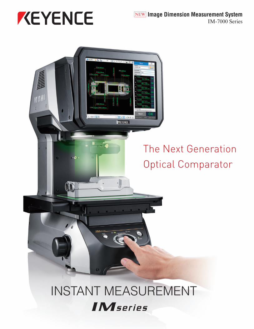
The Next Generation Optical Comparator
INSTANT MEASUREMENT
Image Dimension Measurement SystemIM-7000 Series
NEW
NEW
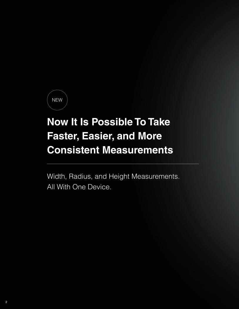
Now It Is Possible To Take
Faster, Easier, and More
Consistent Measurements
Width, Radius, and Height Measurements.
All With One Device.
2
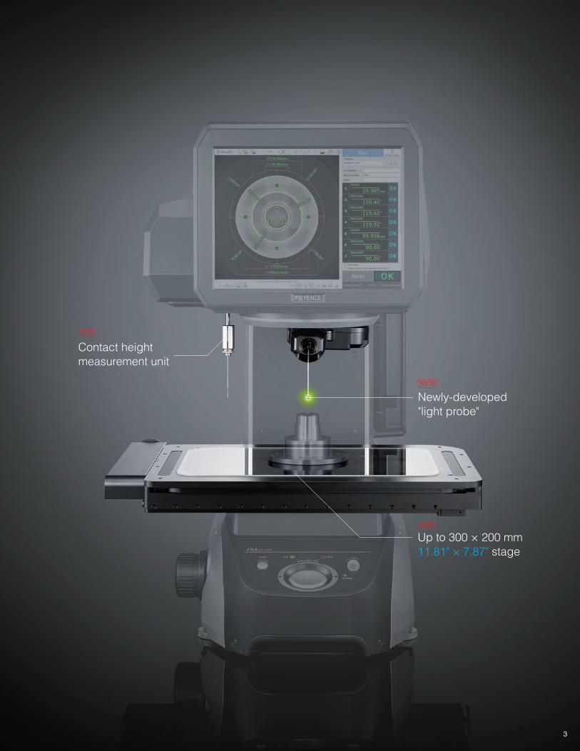
Up to 300 × 200 mm
11.81" × 7.87" stage
Newly-developed
"light probe"
NEW
NEW
3
Contact height
measurement unit
NEW
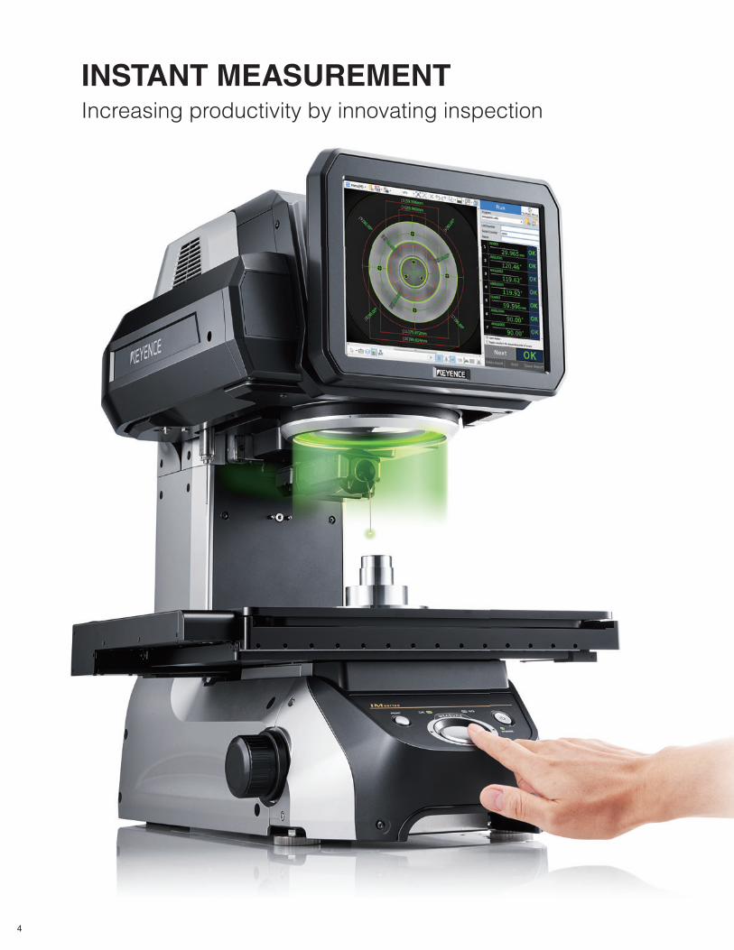
INSTANT MEASUREMENTIncreasing productivity by innovating inspection
4
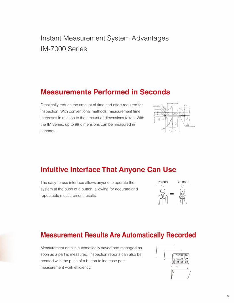
Instant Measurement System Advantages
IM-7000 Series
The easy-to-use interface allows anyone to operate the
system at the push of a button, allowing for accurate and
repeatable measurement results.
Intuitive Interface That Anyone Can Use
70.000 70.000
Drastically reduce the amount of time and effort required for
inspection. With conventional methods, measurement time
increases in relation to the amount of dimensions taken. With
the IM Series, up to 99 dimensions can be measured in
seconds.
Measurements Performed in Seconds
3-M2 (Through-hole)
(Through-hole)
2-R1 (Through-hole)
Measurement Results Are Automatically Recorded
Measurement data is automatically saved and managed as
soon as a part is measured. Inspection reports can also be
created with the push of a button to increase post-
measurement work efficiency.
1 55.754 OK
2 100.015 OK
3 121.151 OK
5
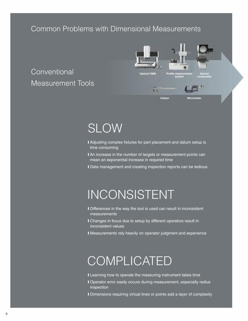
Common Problems with Dimensional Measurements
Conventional
Measurement Tools
SLOW❙ Adjusting complex fi xtures for part placement and datum setup is
time consuming
❙ An increase in the number of targets or measurement points can
mean an exponential increase in required time
❙ Data management and creating inspection reports can be tedious
INCONSISTENT❙ Differences in the way the tool is used can result in inconsistent
measurements
❙ Changes in focus due to setup by different operators result in
inconsistent values
❙ Measurements rely heavily on operator judgment and experience
COMPLICATED❙ Learning how to operate the measuring instrument takes time
❙ Operator error easily occurs during measurement, especially radius
inspection
❙ Dimensions requiring virtual lines or points add a layer of complexity
Optical CMM
Caliper Micrometer
Profi le measurement system
Optical comparator
Mic
co
Calipe
P
6
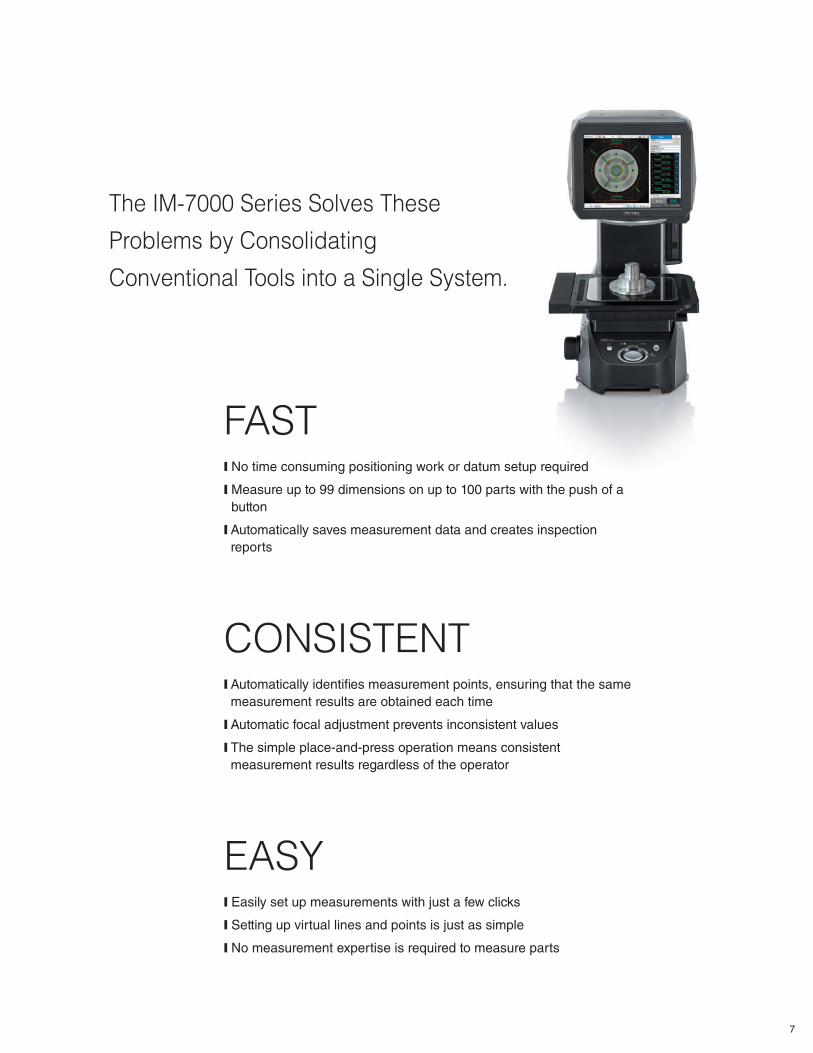
The IM-7000 Series Solves These
Problems by Consolidating
Conventional Tools into a Single System.
FAST❙ No time consuming positioning work or datum setup required
❙ Measure up to 99 dimensions on up to 100 parts with the push of a
button
❙ Automatically saves measurement data and creates inspection
reports
CONSISTENT❙ Automatically identifi es measurement points, ensuring that the same
measurement results are obtained each time
❙ Automatic focal adjustment prevents inconsistent values
❙ The simple place-and-press operation means consistent
measurement results regardless of the operator
EASY❙ Easily set up measurements with just a few clicks
❙ Setting up virtual lines and points is just as simple
❙ No measurement expertise is required to measure parts
setup requireded
7
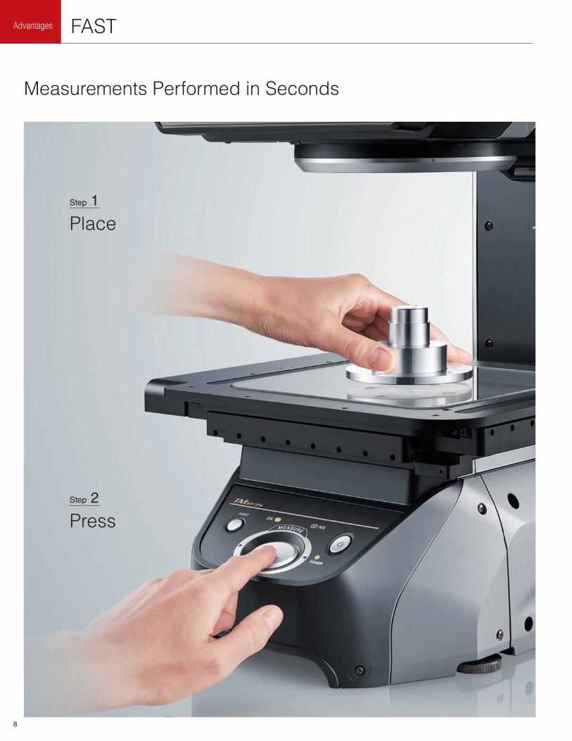
Advantages FAST
Measurements Performed in Seconds
Press
Step 2
Place
Step 1
8
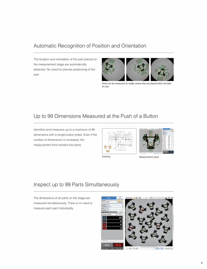
Inspect up to 99 Parts Simultaneously
The dimensions of all parts on the stage are
measured simultaneously. There is no need to
measure each part individually.
Automatic Recognition of Position and Orientation
The location and orientation of the part placed on
the measurement stage are automatically
detected. No need for precise positioning of the
part.
Parts can be measured no matter where they are placed within the fi eld
of view
Up to 99 Dimensions Measured at the Push of a Button
Drawing Measurement result
Identifies and measures up to a maximum of 99
dimensions with a single button press. Even if the
number of dimensions is increased, the
measurement time remains the same.
9
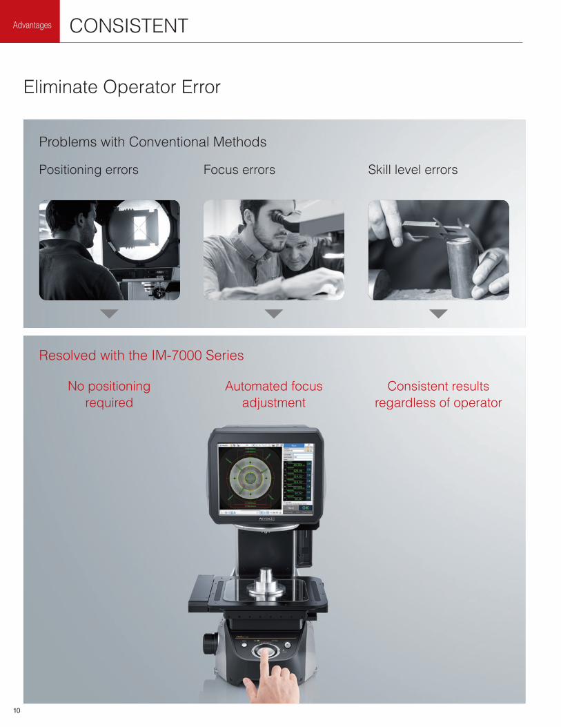
No positioning
required
Advantages CONSISTENT
Eliminate Operator Error
Resolved with the IM-7000 Series
Problems with Conventional Methods
Consistent results
regardless of operator
Automated focus
adjustment
Positioning errors Focus errors Skill level errors
10
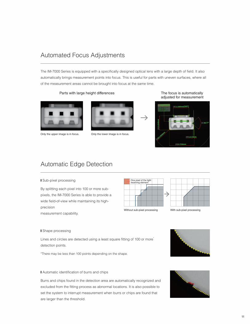
Automated Focus Adjustments
Only the upper image is in focus.
Parts with large height differences
❙ Automatic identification of burrs and chips
Burrs and chips found in the detection area are automatically recognized and
excluded from the fitting process as abnormal locations. It is also possible to
set the system to interrupt measurement when burrs or chips are found that
are larger than the threshold.
Automatic Edge Detection
❙ Sub-pixel processing
By splitting each pixel into 100 or more sub-
pixels, the IM-7000 Series is able to provide a
wide field-of-view while maintaining its high-
precision
measurement capability.
One pixel of the light receiving element
Without sub-pixel processing With sub-pixel processing
Only the lower image is in focus.
The IM-7000 Series is equipped with a specifically designed optical lens with a large depth of field. It also
automatically brings measurement points into focus. This is useful for parts with uneven surfaces, where all
of the measurement areas cannot be brought into focus at the same time.
❙ Shape processing
Lines and circles are detected using a least square fitting of 100 or more*
detection points.
*There may be less than 100 points depending on the shape.
The focus is automatically adjusted for measurement
11
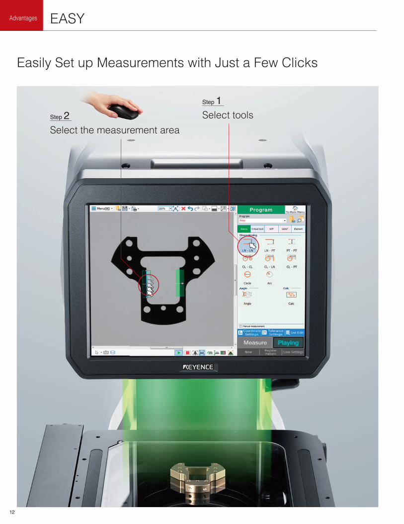
Advantages EASY
Easily Set up Measurements with Just a Few Clicks
Select tools
Step 1
Select the measurement area
Step 2
t th
12
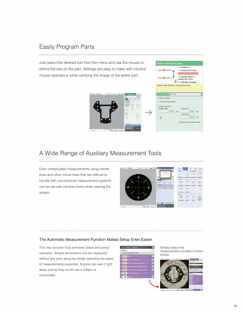
Easily Program Parts
Just select the desired tool from the menu and use the mouse to
define the tool on the part. Settings are easy to make with intuitive
mouse operations while verifying the image of the entire part.
A Wide Range of Auxiliary Measurement Tools
Even complicated measurements using center
lines and other virtual lines that are difficult to
handle with conventional measurement systems
can be set with intuitive clicks while viewing the
screen.
The Automatic Measurement Function Makes Setup Even Easier
This new function truly achieves "place and press"
operation. Simple dimensions can be measured
without any prior setup by simply selecting the types
of measurements expected. Anyone can use it right
away, just as they would use a caliper or
micrometer.
Simply select the measurement condition check boxes
13
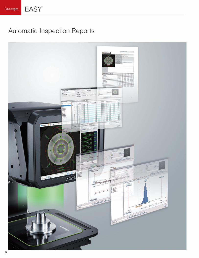
Advantages EASY
Automatic Inspection Reports
14
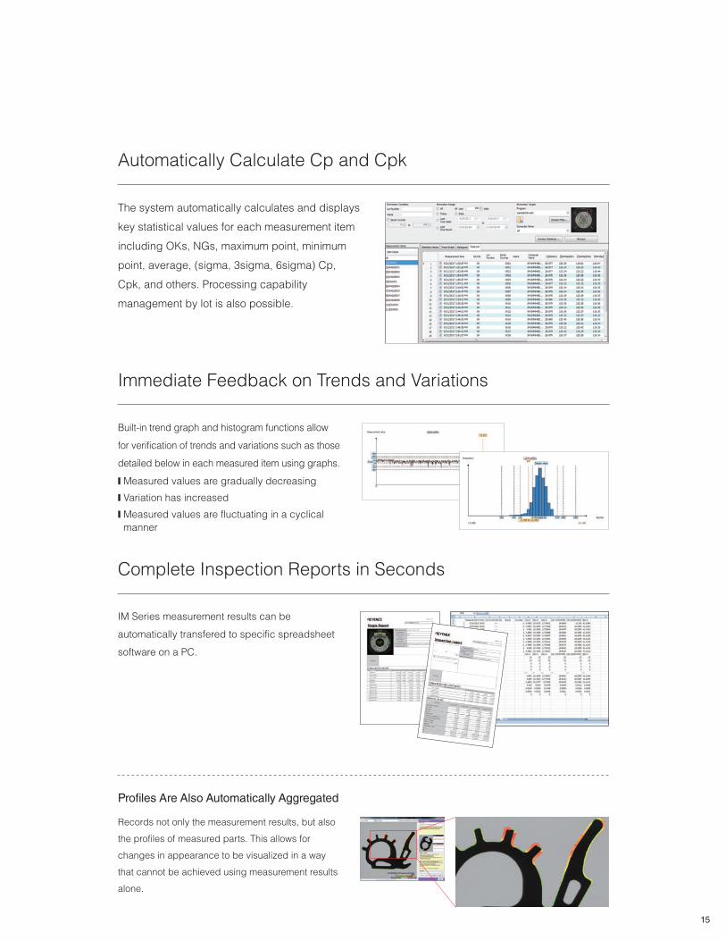
Automatically Calculate Cp and Cpk
The system automatically calculates and displays
key statistical values for each measurement item
including OKs, NGs, maximum point, minimum
point, average, (sigma, 3sigma, 6sigma) Cp,
Cpk, and others. Processing capability
management by lot is also possible.
Immediate Feedback on Trends and Variations
Built-in trend graph and histogram functions allow
for verification of trends and variations such as those
detailed below in each measured item using graphs.
❙ Measured values are gradually decreasing
❙ Variation has increased
❙ Measured values are fluctuating in a cyclical
manner
Complete Inspection Reports in Seconds
IM Series measurement results can be
automatically transfered to specific spreadsheet
software on a PC.
Records not only the measurement results, but also
the profiles of measured parts. This allows for
changes in appearance to be visualized in a way
that cannot be achieved using measurement results
alone.
Profi les Are Also Automatically Aggregated
15
16
Advanced Technologies for
Achieving Place-and-Press
Measurement
Large Diameter Telecentric Lenses
No extreme focus adjustment or
positioning required
Programmable Ring-Illumination Unit
Accurately extracts edges with optimal
lighting conditions
Light Probe Unit
New technology allows measurements of
features at specific heights
Large High Speed/High Precision Stage
6x the measurement volume
17
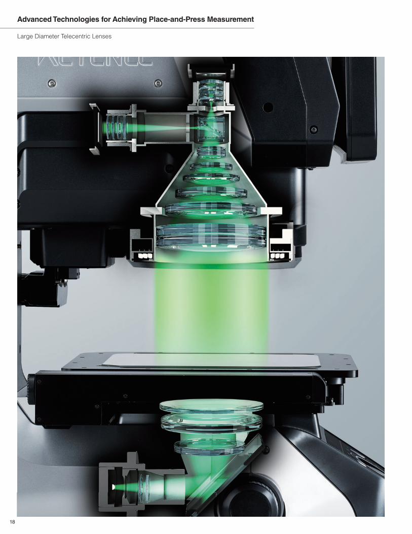
Advanced Technologies for Achieving Place-and-Press Measurement
Large Diameter Telecentric Lenses
18
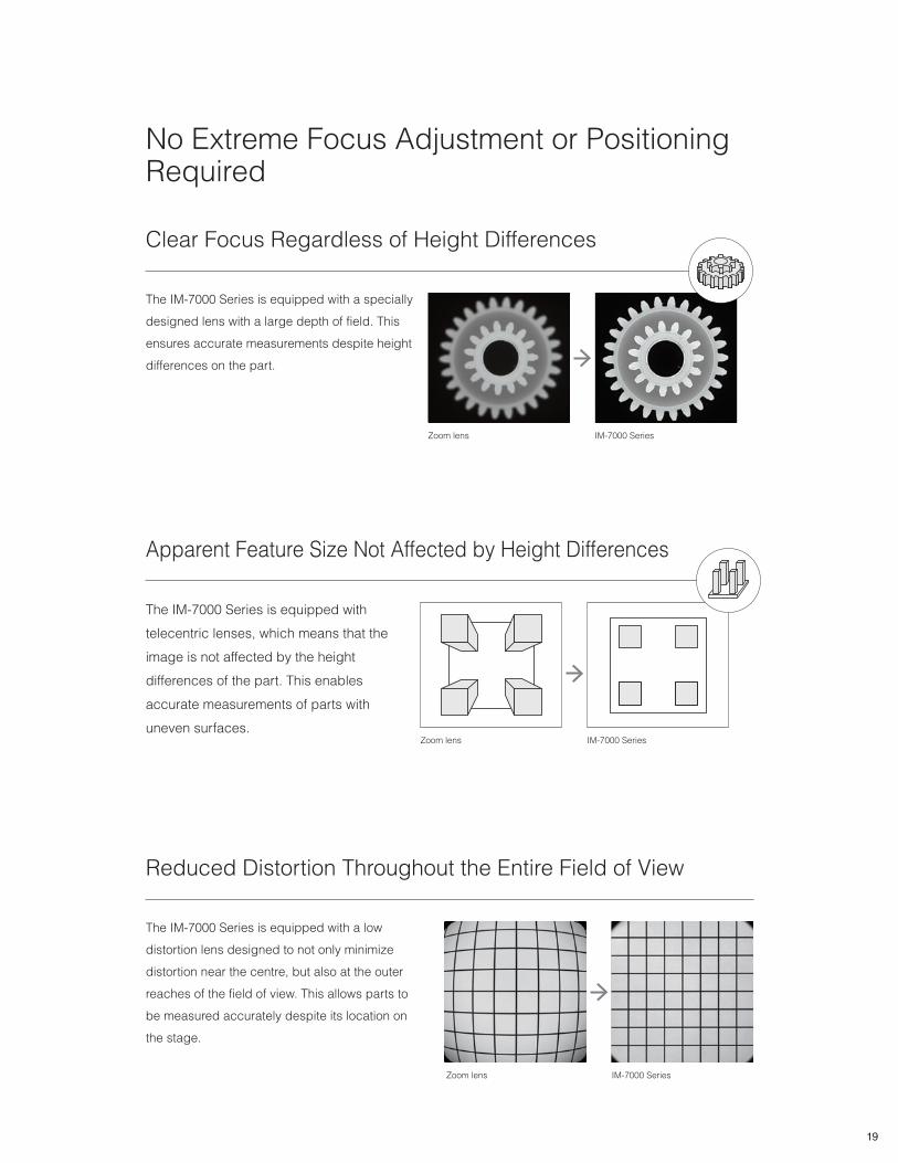
No Extreme Focus Adjustment or Positioning Required
Reduced Distortion Throughout the Entire Field of View
The IM-7000 Series is equipped with a low
distortion lens designed to not only minimize
distortion near the centre, but also at the outer
reaches of the field of view. This allows parts to
be measured accurately despite its location on
the stage.
Zoom lens IM-7000 Series
Clear Focus Regardless of Height Differences
The IM-7000 Series is equipped with a specially
designed lens with a large depth of field. This
ensures accurate measurements despite height
differences on the part.
Zoom lens IM-7000 Series
Apparent Feature Size Not Affected by Height Differences
The IM-7000 Series is equipped with
telecentric lenses, which means that the
image is not affected by the height
differences of the part. This enables
accurate measurements of parts with
uneven surfaces.Zoom lens IM-7000 Series
19
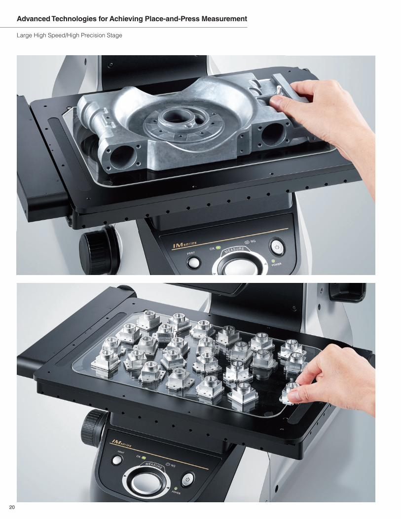
Large High Speed/High Precision Stage
Advanced Technologies for Achieving Place-and-Press Measurement
20
6x the Measurement Volume
Custom High-Precision Linear Scale
A high-precision linear scale designed specifically for the
IM-7000 Series allows the stage movement to be tracked in
micron increments. This makes it possible to perform accurate
measurements, even on large parts.
Measure Taller Parts
Innovations in the structures of the stage system and lens unit have
dramatically improved support for the measurement of tall parts.
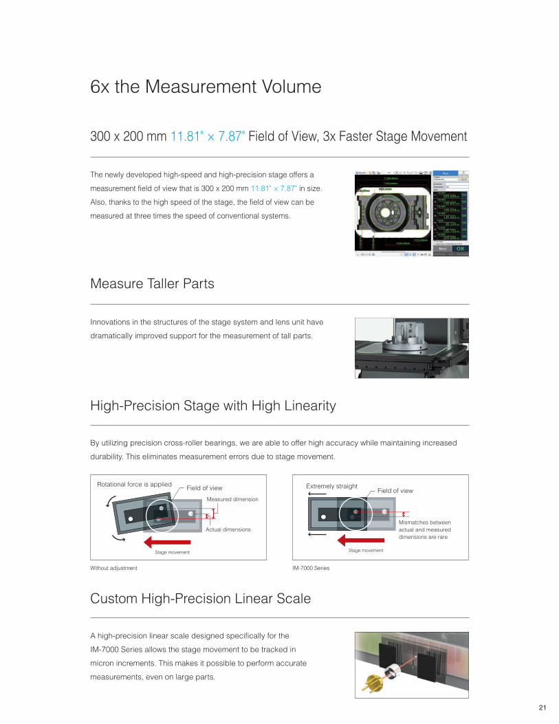
300 x 200 mm 11.81" × 7.87" Field of View, 3x Faster Stage Movement
The newly developed high-speed and high-precision stage offers a
measurement field of view that is 300 x 200 mm 11.81" × 7.87" in size.
Also, thanks to the high speed of the stage, the field of view can be
measured at three times the speed of conventional systems.
High-Precision Stage with High Linearity
By utilizing precision cross-roller bearings, we are able to offer high accuracy while maintaining increased
durability. This eliminates measurement errors due to stage movement.
Without adjustment
Stage movement
Rotational force is applied
Actual dimensions
Measured dimension
Field of view
Stage movement
Extremely straight
Mismatches between
actual and measured
dimensions are rare
Field of view
IM-7000 Series
21
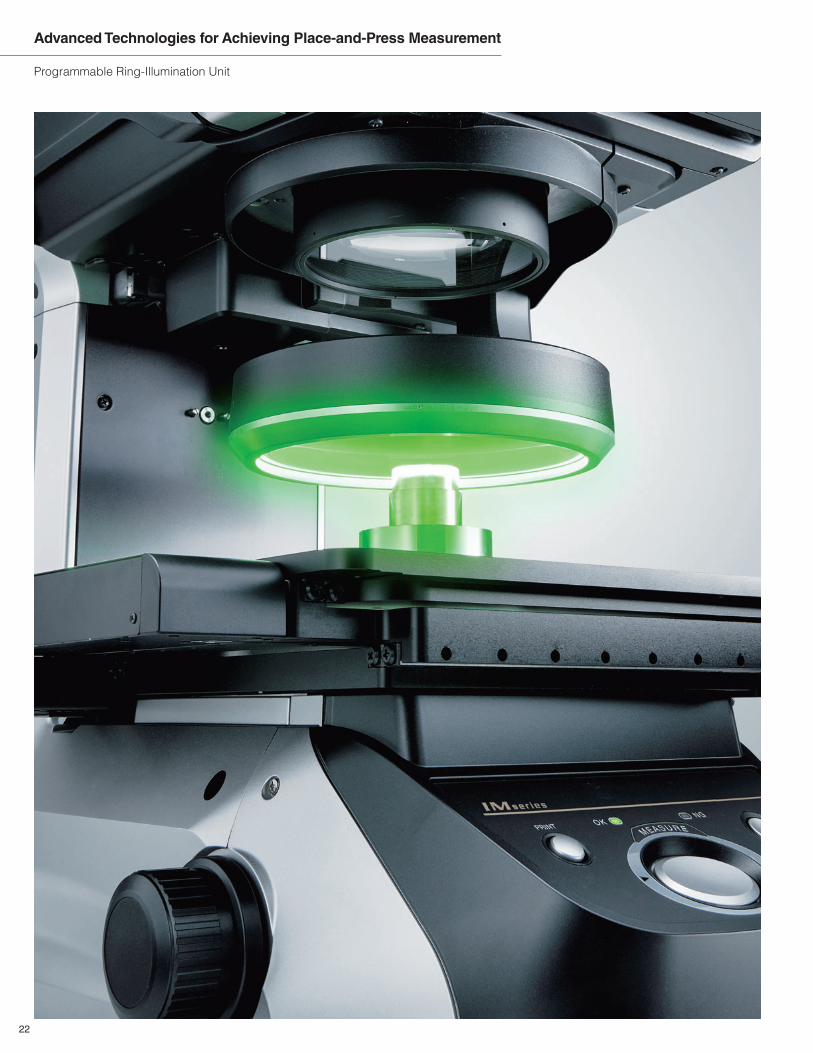
Programmable Ring-Illumination Unit
Advanced Technologies for Achieving Place-and-Press Measurement
22
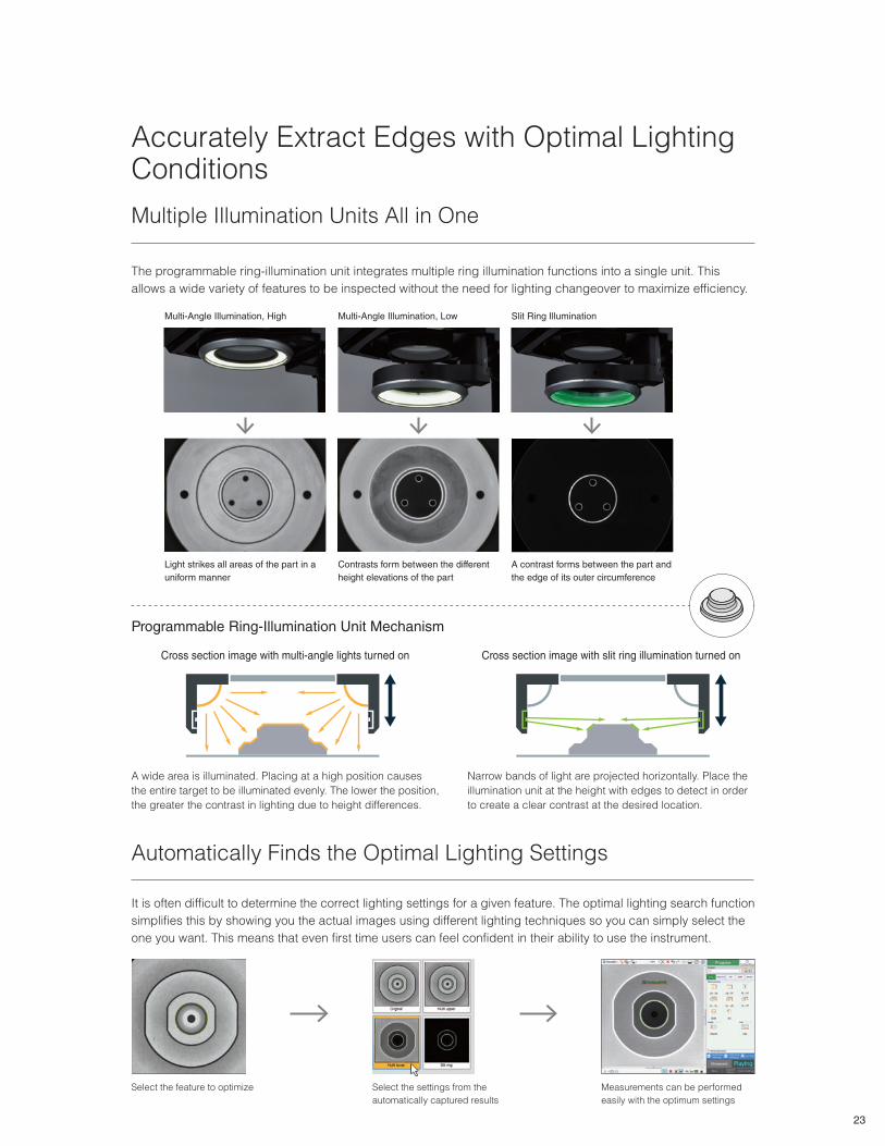
Accurately Extract Edges with Optimal Lighting Conditions
Multiple Illumination Units All in One
The programmable ring-illumination unit integrates multiple ring illumination functions into a single unit. This
allows a wide variety of features to be inspected without the need for lighting changeover to maximize efficiency.
Multi-Angle Illumination, High
Light strikes all areas of the part in a
uniform manner
Multi-Angle Illumination, Low
Contrasts form between the different
height elevations of the part
Slit Ring Illumination
A contrast forms between the part and
the edge of its outer circumference
Programmable Ring-Illumination Unit Mechanism
Cross section image with multi-angle lights turned on
A wide area is illuminated. Placing at a high position causes
the entire target to be illuminated evenly. The lower the position,
the greater the contrast in lighting due to height differences.
Narrow bands of light are projected horizontally. Place the
illumination unit at the height with edges to detect in order
to create a clear contrast at the desired location.
Cross section image with slit ring illumination turned on
Automatically Finds the Optimal Lighting Settings
It is often difficult to determine the correct lighting settings for a given feature. The optimal lighting search function
simplifies this by showing you the actual images using different lighting techniques so you can simply select the
one you want. This means that even first time users can feel confident in their ability to use the instrument.
Select the feature to optimize Select the settings from the
automatically captured results
Measurements can be performed
easily with the optimum settings
23
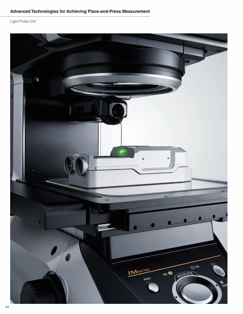
Light Probe Unit
Advanced Technologies for Achieving Place-and-Press Measurement
24
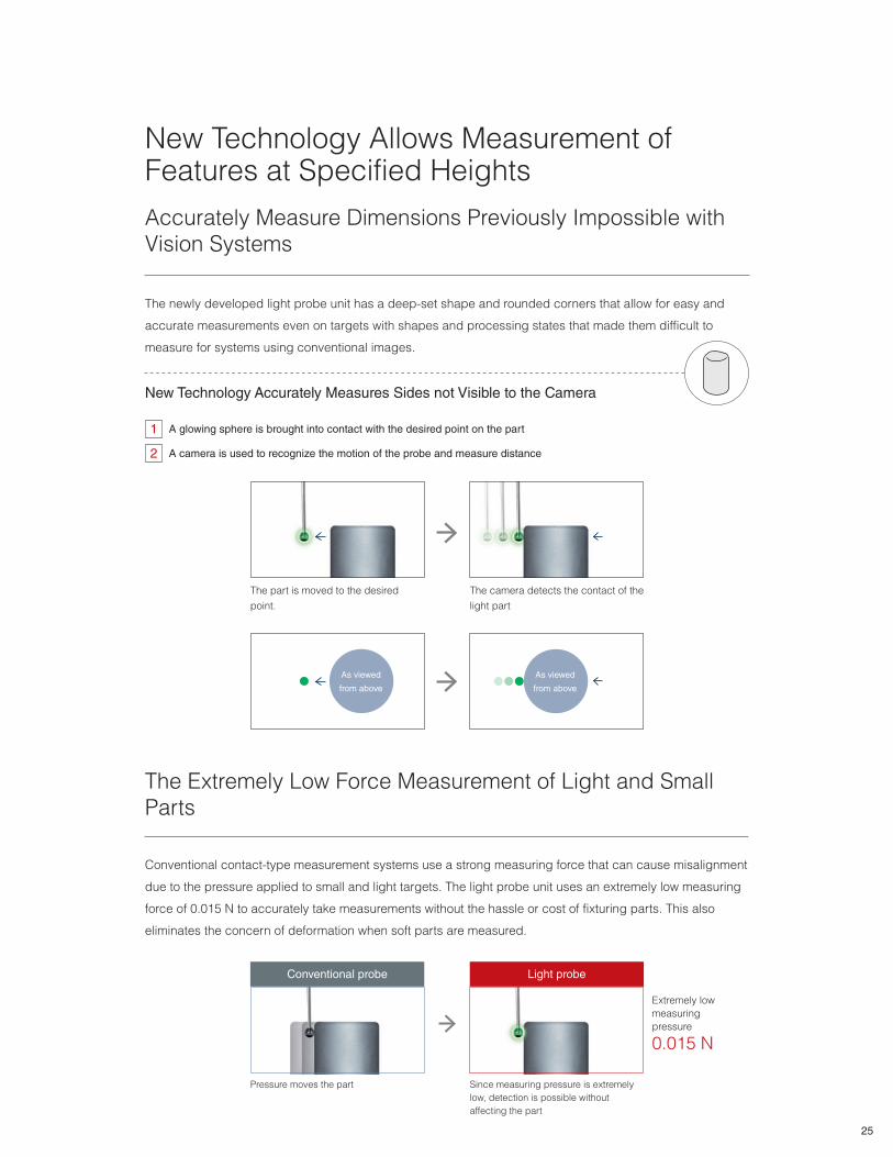
New Technology Allows Measurement of Features at Specified Heights
New Technology Accurately Measures Sides not Visible to the Camera
A glowing sphere is brought into contact with the desired point on the part1
A camera is used to recognize the motion of the probe and measure distance2
Accurately Measure Dimensions Previously Impossible with Vision Systems
The Extremely Low Force Measurement of Light and Small Parts
The newly developed light probe unit has a deep-set shape and rounded corners that allow for easy and
accurate measurements even on targets with shapes and processing states that made them difficult to
measure for systems using conventional images.
Conventional contact-type measurement systems use a strong measuring force that can cause misalignment
due to the pressure applied to small and light targets. The light probe unit uses an extremely low measuring
force of 0.015 N to accurately take measurements without the hassle or cost of fixturing parts. This also
eliminates the concern of deformation when soft parts are measured.
The part is moved to the desired
point.
As viewed
from above
As viewed
from above
The camera detects the contact of the
light part
Pressure moves the part
Conventional probe Light probe
Since measuring pressure is extremely
low, detection is possible without
affecting the part
Extremely low
measuring
pressure
0.015 N
25
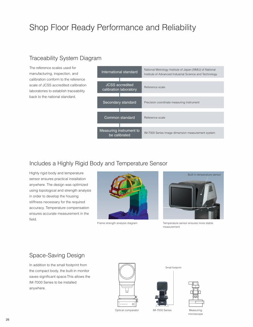
Shop Floor Ready Performance and Reliability
Traceability System Diagram
Space-Saving Design
In addition to the small footprint from
the compact body, the built-in monitor
saves significant space.This allows the
IM-7000 Series to be installed
anywhere.
The reference scales used for
manufacturing, inspection, and
calibration conform to the reference
scale of JCSS accredited calibration
laboratories to establish traceability
back to the national standard.
International standardNational Metrology Institute of Japan (NMIJ) of National
Institute of Advanced Industrial Science and Technology
JCSS accredited
calibration laboratoryReference scale
Secondary standard Precision coordinate measuring instrument
Common standard Reference scale
Measuring instrument to
be calibratedIM-7000 Series image dimension measurement system
Optical comparator IM-7000 Series Measuring
microscope
Small footprint
Includes a Highly Rigid Body and Temperature Sensor
Highly rigid body and temperature
sensor ensures practical installation
anywhere. The design was optimized
using topological and strength analysis
in order to develop the housing
stiffness necessary for the required
accuracy. Temperature compensation
ensures accurate measurement in the
field.Frame strength analysis diagram Temperature sensor ensures more stable
measurement
Built-in temperature sensor
26

Quality Support Only Possible
With a Direct Sales System
Our comprehensive after-sales support through
technical sales technicians can only be achieved by
our direct sales system. You can be confident that you
will get the support you want immediately, without the
hassle and delay of dealing with reps or distributors.Direct Sales
Other Manufacturers
Customer
Customer KEYENCE
Sales Company
Distributor Manufacturer
KEYENCE
Comprehensive Coverage All Over the World &
Global Support System
Support for Multiple Languages
In addition to the system's control screen, manuals
and other documentation are also provided in a wide
range of languages. Local staff can easily use
KEYENCE's products after they are installed at
international manufacturing bases.
Languages
*To be released periodically
English German French
Italian Simplified Chinese Traditional Chinese
Spanish Thai Korean
Instant Delivery System Also Available
Internationally
KEYENCE's product inventory is not limited to Japan. A wide
variety of products are stocked at distribution sites in each country
so that they can be delivered promptly on the day we receive your
order. You do not need to worry about if it may take considerable
effort and time to obtain a product from an overseas factory.
KEYENCE(UK)
LIMITED
KEYENCE CORPORATIONOF AMERICA
KEYENCE SINGAPORE PTE LTD.KEYENCE (MALAYSIA) SDN BHD
KEYENCE INDIA PVT. LTD.
KEYENCE (THAILAND) CO., LTD.
KEYENCEDEUTSCHLAND GmbH
KEYENCE TAIWAN CO., LTD.
KOREA KEYENCE CO., LTD.KEYENCE FRANCE SAS
KEYENCE (HONG KONG) CO., LTD.
KEYENCE (CHINA) CO., LTD.KEYENCE ITALIA S.p.A.
KEYENCE CANADA INC.
KEYENCE MEXICOS.A. DE C.V.
KEYENCE BRASIL
KEYENCE INTERNATIONAL (BELGIUM) NV/SA
PT. KEYENCE INDONESIA
Head Office
KEYENCE VIETNAM CO., LTD.KEYENCE PHILIPPINES INC.
KEYENCECORPORATION
WWL1_1037
27
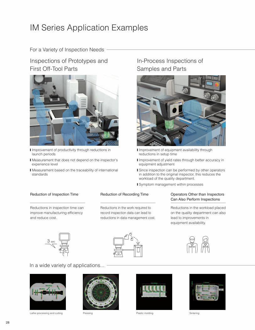
IM Series Application Examples
For a Variety of Inspection Needs
In-Process Inspections of
Samples and Parts
❙ Improvement of equipment availability through reductions in setup time
❙ Improvement of yield rates through better accuracy in equipment adjustment
❙ Since inspection can be performed by other operators in addition to the original inspector, this reduces the workload of the quality department.
❙ Symptom management within processes
Inspections of Prototypes and
First Off-Tool Parts
❙ Improvement of productivity through reductions in launch periods
❙ Measurement that does not depend on the inspector's experience level
❙ Measurement based on the traceability of international standards
In a wide variety of applications...
Lathe processing and cutting Pressing Plastic molding Sintering
Operators Other than Inspectors
Can Also Perform Inspections
Reductions in the workload placed
on the quality department can also
lead to improvements in
equipment availability.
Reduction of Inspection Time
Reductions in inspection time can
improve manufacturing efficiency
and reduce cost.
3 sec
Reduction of Recording Time
Reductions in the work required to
record inspection data can lead to
reductions in data management cost.
28
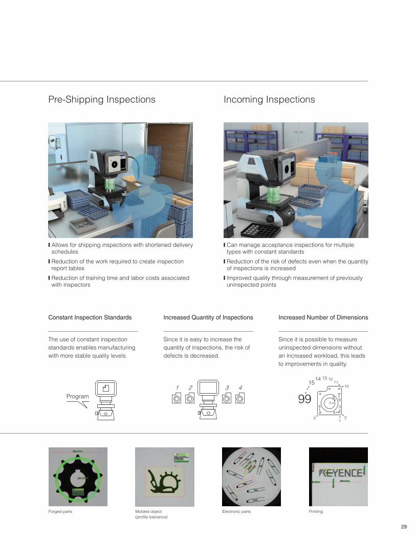
Pre-Shipping Inspections
❙ Allows for shipping inspections with shortened delivery schedules
❙ Reduction of the work required to create inspection report tables
❙ Reduction of training time and labor costs associated with inspectors
Incoming Inspections
❙ Can manage acceptance inspections for multiple types with constant standards
❙ Reduction of the risk of defects even when the quantity of inspections is increased
❙ Improved quality through measurement of previously uninspected points
12
3
4
5
67
89
1011
12131415
99
Increased Number of Dimensions
Since it is possible to measure
uninspected dimensions without
an increased workload, this leads
to improvements in quality.
Increased Quantity of Inspections
Since it is easy to increase the
quantity of inspections, the risk of
defects is decreased.
1 2 3 4
Constant Inspection Standards
The use of constant inspection
standards enables manufacturing
with more stable quality levels.
Program
Forged parts Molded object
(profile tolerance)
Electronic parts Printing
29
The probe automatically performs the
measurements
Display the height measurement resultsSimply place the target on the stage and press
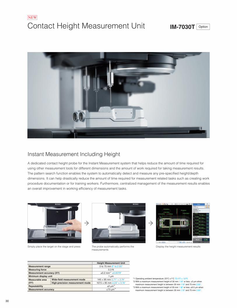
Contact Height Measurement Unit IM-7030T Option
Instant Measurement Including Height
A dedicated contact height probe for the Instant Measurement system that helps reduce the amount of time required for
using other measurement tools for different dimensions and the amount of work required for taking measurement results.
The pattern search function enables the system to automatically detect and measure any pre-specified height/depth
dimensions. It can help drastically reduce the amount of time required for measurement related tasks such as creating work
procedure documentation or for training workers. Furthermore, centralized management of the measurement results enables
an overall improvement in working efficiency of measurement tasks.
Height Measurement Unit
Measurement range 0 to 75 mm 0" to 2.95"
Measuring force 0.3 N
Measurement accuracy (XY) ±0.2 mm*1 ±0.0079"
Minimum display unit 1 μm
Measurable area
(XY)
Wide-fi eld measurement mode 145 × 95 mm 5.71" × 3.74"
High-precision measurement mode 107.5 × 95 mm 4.23" × 3.74"
Repeatability ±2 μm*2
Measurement accuracy ±7.5 μm*3
*1 Operating ambient temperature: 23°C ±1°C 73.4°F ± 1.8°F.
*2 With a maximum measurement height of 30 mm 1.18" or less. ±3 μm when
maximum measurement height is between 30 mm 1.18" and 75 mm 2.95".
*3 With a maximum measurement height of 30 mm 1.18" or less. ±9.5 μm when
maximum measurement height is between 30 mm 1.18" and 75 mm 2.95".
30
NEW
Network Functions and Software
CAD import module
Import CAD Data Optional: IM-H2C
The data required for measurements can be acquired from CAD drawing data in DXF format.
Even when a target is not at hand, it is still possible to quickly create measurement setting files.
*Measurement setup editor (IM-H2EA) is also required.
Measurement setup editor
Offline Programming Optional: IM-H2EA
A PC can be used to add or change measurement locations in a setting file created by the IM-7000 Series system, or in
data created with the CAD import module.
Data transfer software
Creating Inspection Reports Optional: IM-H1T
IM Series measurement results can be automatically transfered to specific cells in spreadsheet software on a specified PC.
Data transfer over a LAN connection
Communicating with PCs
It is easy to transfer a setting file created on an IM Series system or a PC to another IM Series system in another location.
PC software operating environment
Supported OS
Windows 7 Ultimate/Professional/Home Premium (64-bit version)
Windows 8.1/Windows 8.1 Pro (64-bit version)
Windows 10 Home/Pro/Enterprise (64-bit version)
Required free space on hard disk 5 GB or more
● Windows® is a trademark or registered trademark of Microsoft Corporation in the United States and other countries.● The formal name of Windows is Microsoft Windows® operating system.
31
Keyboard(Accessory)
IM-7010Head
Mouse(Accessory)
IM-7001Controller
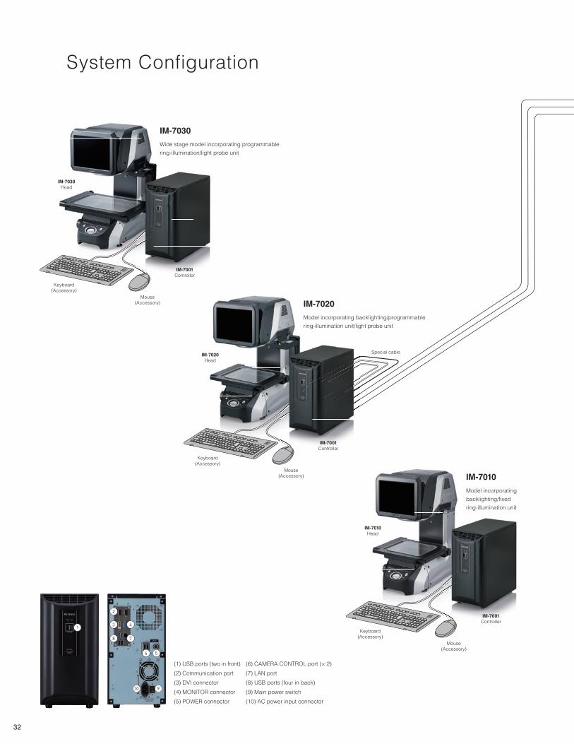
IM-7010
Model incorporating
backlighting/fixed
ring-illumination unit
Keyboard(Accessory)
IM-7030Head
Mouse(Accessory)
IM-7001Controller
IM-7030
Wide stage model incorporating programmable
ring-illumination/light probe unit
Keyboard(Accessory)
IM-7020Head
Mouse(Accessory)
IM-7001Controller
IM-7020
Model incorporating backlighting/programmable
ring-illumination unit/light probe unit
Special cable
System Configuration
1
2
3 4
8 7
6
10
5
9
(1) USB ports (two in front)
(2) Communication port
(3) DVI connector
(4) MONITOR connector
(5) POWER connector
(6) CAMERA CONTROL port (× 2)
(7) LAN port
(8) USB ports (four in back)
(9) Main power switch
(10) AC power input connector
32
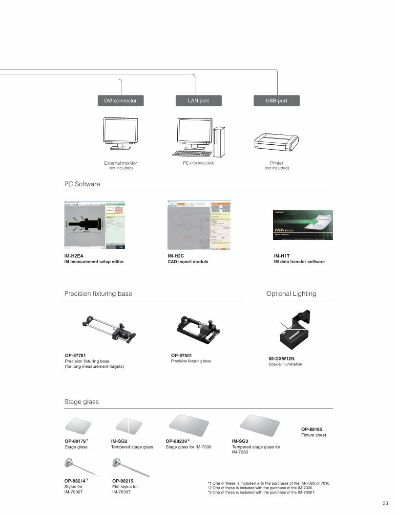
DVI connector LAN port USB port
External monitor(not included)
PC (not included) Printer(not included)
OP-88185
Fixture sheet
IM-DXW12NCoaxial illumination
Optional Lighting
PC Software
IM-SG2
Tempered stage glass
OP-88179*1
Stage glass
IM-H1T
IM data transfer software
IM-H2EA
IM measurement setup editor
*1 One of these is included with the purchase of the IM-7020 or 7010.*2 One of these is included with the purchase of the IM-7030.*3 One of these is included with the purchase of the IM-7030T.
OP-88239*2
Stage glass for IM-7030
IM-SG3
Tempered stage glass for
IM-7030
Stage glass
OP-87761
Precision fixturing base
(for long measurement targets)
OP-87501Precision fixturing base
Precision fixturing base
OP-88215
Flat stylus for
IM-7030T
OP-88214*3
Stylus for
IM-7030T
IM-H2C
CAD import module
33
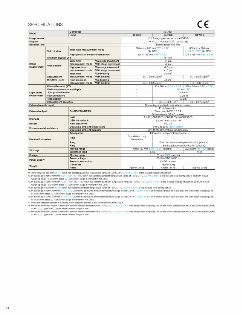
ModelController IM-7001
Head IM-7010 IM-7020 IM-7030
Image sensor 1” 6.6 mega pixel monochrome CMOS
Display 10. 4” LCD monitor (XGA: 1024 × 768)
Receiver lens Double telecentric lens
Image
measurement
Field of viewWide-fi eld measurement mode
200 mm × 200 mm 7.87" × 7.87"
(4× R50)
300 mm × 200 mm
11.81" × 7.87" (4× R50)
High-precision measurement mode 125 × 125 mm 4.92" × 4.92" 225 × 125 mm 8.86" × 4.92"
Minimum display unit 0.1 μm
Repeatability
Wide-fi eld
measurement mode
W/o stage movement ±1 μm
With stage movement ±2 μm
High-precision
measurement mode
W/o stage movement ±0.5 μm
With stage movement ±1.5 μm
Measurement
accuracy (±2 )
Wide-fi eld
measurement mode
W/o binding ±5 μm*1
With binding ±(7 + 0.02 L) μm*2 ±(7 + 0.02 L) μm*3
High-precision
measurement mode
W/o binding ±2 μm*4
With binding ±(4 + 0.02 L) μm*5 ± (4 + 0.02 L) μm*6
Light probe
Measurement
Measurable area (XY) - 90 × 90 mm 3.54" × 3.54" 190 × 90 mm 7.48" × 3.54"
Maximum measurement depth - 30 mm 1.18"
Light probe diameter - ø3 mm
Measuring force - 0.015 N
Repeatability - ±2 μm*7
Measurement accuracy - ±(8 + 0.02 L) μm*8 ±(8 + 0.02 L) μm*9
External remote input Non-voltage input (with and without contact)
External output OK/NG/FAIL/MEAS.
PhotoMos output
Rated load 24 VDC 0.5 A
ON resistance 50 mΩ or lower
InterfaceLAN RJ-45 (10BASE-T/100BASE-TX/1000BASE-T)
USB 2.0 series A 6 ports (front: 2, rear: 4)
Record Hard disk drive 500 GB
Environmental resistanceOperating ambient temperature +10°C to 35°C +50°F to 95°F
Operating ambient humidity 20% RH to 80% RH (no condensation)
Illumination system
Transparent Telecentric transparent illumination
RingFour division ring
illumination-
Ring - Four division, multi-angle illumination (electric)
Ring - Slit ring (directivity) illumination (electric)
XY stageMoving range 100 × 100 mm 3.94" × 3.94" (electric) 200 × 100 mm 7.87" × 3.94" (electric)
Withstand load 5 kg 7.5 kg
Z stage Moving range 75 mm 2.95" (electric)
Power supplyPower voltage 100–240 VAC, 50/60 Hz
Power consumption 430 VA or lower
WeightController Approx. 8 kg
Head Approx. 30 kg Approx. 31 kg Approx. 33 kg
*1. In the range of ø80 mm ø3.15", within the operating ambient temperature range of +23°C ±1°C +73.4°F ± 1.8°F at the focused focal point position
*2. In the range of 180 × 180 mm 7.09" × 7.09" (4× R40), within the operating ambient temperature range of +23°C ±1°C +73.4°F ± 1.8°F at the focused focal point position, and with a load
weighing 2 kg or less on the stage (L = amount of stage movement in mm units)
*3. In the range of 280 × 180 mm 11.02" × 7.09" (4× R40), within the operating ambient temperature range of +23°C ±1°C +73.4°F ± 1.8°F at the focused focal point position, and with a load
weighing 3 kg or less on the stage (L = amount of stage movement in mm units)
*4. In the range of ø20 mm ø0.79" within the operating ambient temperature range of +23°C ±1°C +73.4°F ± 1.8°F at the focused focal point position
*5. In the range of 120 × 120 mm 4.72" × 4.72", within the operating ambient temperature range of +23°C ±1°C +73.4°F ± 1.8°F at the focused focal point position, and with a load weighing 2 kg
or less on the stage (L = amount of stage movement in mm units)
*6. In the range of 220 × 120 mm 9.45" × 4.72", within the operating ambient temperature range of +23°C ±1°C +73.4°F ± 1.8°F at the focused focal point position, and with a load weighing 3 kg
or less on the stage (L = amount of stage movement in mm units)
*7. When the detection system is standard. If the detection system is at a deep position, then ±3 μm
*8. When the detection system is standard, and the ambient temperature is +23°C ±1°C +73.4°F ± 1.8°F, with a stage load weighing 2 kg or less. If the detection system is at a deep position, then
±(10 + 0.02 L) μm with L as the measurement length in mm.
*9. When the detection system is standard, and the ambient temperature is +23°C ±1°C +73.4°F ± 1.8°F, with a stage load weighing 3 kg or less. If the detection system is at a deep position, then
±(10 + 0.02 L) μm with L as the measurement length in mm.
SPECIFICATIONS
34
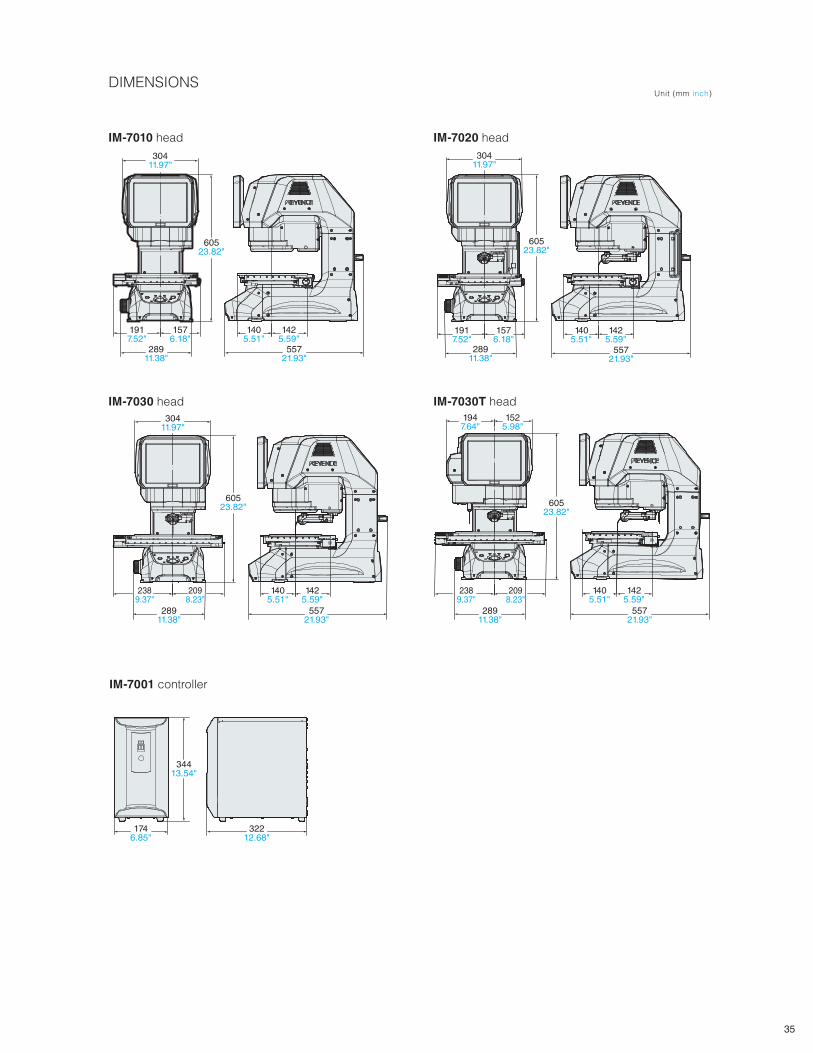
DIMENSIONS
28911.38"
1576.18"
1917.52"
60523.82"
30411.97"
1425.59"
1405.51"
55721.93"
1576.18"
1917.52"
60523.82"
28911.38"
30411.97"
1425.59"
1405.51"
55721.93"
32212.68"
1746.85"
34413.54"
2098.23"
2389.37"
28911.38"
60523.82"
30411.97"
1425.59"
1405.51"
55721.93"
60523.82"
28911.38"
2098.23"
2389.37"
1525.98"
1947.64"
55721.93"
1405.51"
1425.59"
Unit (mm inch)
IM-7010 head
IM-7030 head
IM-7020 head
IM-7030T head
IM-7001 controller
35

www.keyence.com
IM7000-KA-C2-US 1028-1 611G17 Copyright (c) 2018 KEYENCE CORPORATION. All rights reserved.
E-mail: [email protected]
E-mail: [email protected] E-mail: [email protected]


