
SSAAFFEETTYYWWAARRNNIINNGGOnly qualified personnel should install and service the equipment. The installation, starting up, and servicing of heating, ventilating, and
air-conditioning equipment can be hazardous and requires specific knowledge and training. Improperly installed, adjusted or altered
equipment by an unqualified person could result in death or serious injury. When working on the equipment, observe all precautions in the
literature and on the tags, stickers, and labels that are attached to the equipment.
August 2015 SSP-SVX14D-EN
Split System Air ConditionersOdyssey™™Heat Pump Condenser — 5 to 20 Tons
((6600 HHzz))
TWA073D***A
TWA090D***A
TWA120D***B
TWA180E***A
TWA240E***A
((5500 HHzz))
TWA061D***A
TWA076D***A
TWA101D***B
TWA156E***A
TWA201E***A
Installation, Operation,and Maintenance

©2015 Trane All rights reserved SSP-SVX14D-EN
IntroductionRead this manual thoroughly before operating or
servicing this unit.
Warnings, Cautions, and NoticesSafety advisories appear throughout this manual as
required. Your personal safety and the proper
operation of this machine depend upon the strict
observance of these precautions.
The three types of advisories are defined as follows:
WARNINGIndicates a potentially hazardous situationwhich, if not avoided, could result in death orserious injury.
CAUTIONIndicates a potentially hazardous situationwhich, if not avoided, could result in minor ormoderate injury. It could also be used to alertagainst unsafe practices.
NOTICEIndicates a situation that could result inequipment or property-damage onlyaccidents.
Important Environmental ConcernsScientific research has shown that certain man-made
chemicals can affect the earth’s naturally occurring
stratospheric ozone layer when released to the
atmosphere. In particular, several of the identified
chemicals that may affect the ozone layer are
refrigerants that contain Chlorine, Fluorine and Carbon
(CFCs) and those containing Hydrogen, Chlorine,
Fluorine and Carbon (HCFCs). Not all refrigerants
containing these compounds have the same potential
impact to the environment. Trane advocates the
responsible handling of all refrigerants-including
industry replacements for CFCs such as HCFCs and
HFCs.
Important Responsible RefrigerantPracticesTrane believes that responsible refrigerant practices are
important to the environment, our customers, and the
air conditioning industry. All technicians who handle
refrigerants must be certified. The Federal Clean Air Act
(Section 608) sets forth the requirements for handling,
reclaiming, recovering and recycling of certain
refrigerants and the equipment that is used in these
service procedures. In addition, some states or
municipalities may have additional requirements that
must also be adhered to for responsible management
of refrigerants. Know the applicable laws and follow
them.
WWAARRNNIINNGGPPrrooppeerr FFiieelldd WWiirriinngg aanndd GGrroouunnddiinngg
RReeqquuiirreedd!!FFaaiilluurree ttoo ffoollllooww ccooddee ccoouulldd rreessuulltt iinn ddeeaatthh oorr
sseerriioouuss iinnjjuurryy..
AAllll ffiieelldd wwiirriinngg MMUUSSTT bbee ppeerrffoorrmmeedd bbyy qquuaalliiffiieedd
ppeerrssoonnnneell.. IImmpprrooppeerrllyy iinnssttaalllleedd aanndd ggrroouunnddeedd
ffiieelldd wwiirriinngg ppoosseess FFIIRREE aanndd EELLEECCTTRROOCCUUTTIIOONN
hhaazzaarrddss.. TToo aavvooiidd tthheessee hhaazzaarrddss,, yyoouu MMUUSSTT ffoollllooww
rreeqquuiirreemmeennttss ffoorr ffiieelldd wwiirriinngg iinnssttaallllaattiioonn aanndd
ggrroouunnddiinngg aass ddeessccrriibbeedd iinn NNEECC aanndd yyoouurr llooccaall//
ssttaattee eelleeccttrriiccaall ccooddeess..
WWAARRNNIINNGGPPeerrssoonnaall PPrrootteeccttiivvee EEqquuiippmmeenntt ((PPPPEE))
RReeqquuiirreedd!!FFaaiilluurree ttoo wweeaarr pprrooppeerr PPPPEE ffoorr tthhee jjoobb bbeeiinngg
uunnddeerrttaakkeenn ccoouulldd rreessuulltt iinn ddeeaatthh oorr sseerriioouuss iinnjjuurryy..
TTeecchhnniicciiaannss,, iinn oorrddeerr ttoo pprrootteecctt tthheemmsseellvveess ffrroomm
ppootteennttiiaall eelleeccttrriiccaall,, mmeecchhaanniiccaall,, aanndd cchheemmiiccaall
hhaazzaarrddss,, MMUUSSTT ffoollllooww pprreeccaauuttiioonnss iinn tthhiiss mmaannuuaall
aanndd oonn tthhee ttaaggss,, ssttiicckkeerrss,, aanndd llaabbeellss,, aass wweellll aass tthhee
iinnssttrruuccttiioonnss bbeellooww::
•• BBeeffoorree iinnssttaalllliinngg//sseerrvviicciinngg tthhiiss uunniitt,,
tteecchhnniicciiaannss MMUUSSTT ppuutt oonn aallll PPPPEE rreeqquuiirreedd ffoorr
tthhee wwoorrkk bbeeiinngg uunnddeerrttaakkeenn ((EExxaammpplleess;; ccuutt
rreessiissttaanntt gglloovveess//sslleeeevveess,, bbuuttyyll gglloovveess,, ssaaffeettyy
ggllaasssseess,, hhaarrdd hhaatt//bbuummpp ccaapp,, ffaallll pprrootteeccttiioonn,,
eelleeccttrriiccaall PPPPEE aanndd aarrcc ffllaasshh ccllootthhiinngg))..
AALLWWAAYYSS rreeffeerr ttoo aapppprroopprriiaattee MMaatteerriiaall SSaaffeettyy
DDaattaa SShheeeettss ((MMSSDDSS))//SSaaffeettyy DDaattaa SShheeeettss
((SSDDSS)) aanndd OOSSHHAA gguuiiddeelliinneess ffoorr pprrooppeerr PPPPEE..
•• WWhheenn wwoorrkkiinngg wwiitthh oorr aarroouunndd hhaazzaarrddoouuss
cchheemmiiccaallss,, AALLWWAAYYSS rreeffeerr ttoo tthhee aapppprroopprriiaattee
MMSSDDSS//SSDDSS aanndd OOSSHHAA//GGHHSS ((GGlloobbaall
HHaarrmmoonniizzeedd SSyysstteemm ooff CCllaassssiiffiiccaattiioonn aanndd
LLaabbeelllliinngg ooff CChheemmiiccaallss)) gguuiiddeelliinneess ffoorr
iinnffoorrmmaattiioonn oonn aalllloowwaabbllee ppeerrssoonnaall eexxppoossuurree
lleevveellss,, pprrooppeerr rreessppiirraattoorryy pprrootteeccttiioonn aanndd
hhaannddlliinngg iinnssttrruuccttiioonnss..
•• IIff tthheerree iiss aa rriisskk ooff eenneerrggiizzeedd eelleeccttrriiccaall
ccoonnttaacctt,, aarrcc,, oorr ffllaasshh,, tteecchhnniicciiaannss MMUUSSTT ppuutt
oonn aallll PPPPEE iinn aaccccoorrddaannccee wwiitthh OOSSHHAA,, NNFFPPAA
7700EE,, oorr ootthheerr ccoouunnttrryy--ssppeecciiffiicc rreeqquuiirreemmeennttss
ffoorr aarrcc ffllaasshh pprrootteeccttiioonn,, PPRRIIOORR ttoo sseerrvviicciinngg
tthhee uunniitt.. NNEEVVEERR PPEERRFFOORRMM AANNYY SSWWIITTCCHHIINNGG,,
DDIISSCCOONNNNEECCTTIINNGG,, OORR VVOOLLTTAAGGEE TTEESSTTIINNGG
WWIITTHHOOUUTT PPRROOPPEERR EELLEECCTTRRIICCAALL PPPPEE AANNDD
AARRCC FFLLAASSHH CCLLOOTTHHIINNGG.. EENNSSUURREE
EELLEECCTTRRIICCAALL MMEETTEERRSS AANNDD EEQQUUIIPPMMEENNTTAARREE
PPRROOPPEERRLLYY RRAATTEEDD FFOORR IINNTTEENNDDEEDD VVOOLLTTAAGGEE..
SSP-SVX14D-EN 3
WWAARRNNIINNGGRReeffrriiggeerraanntt uunnddeerr HHiigghh PPrreessssuurree!!FFaaiilluurree ttoo ffoollllooww iinnssttrruuccttiioonnss bbeellooww ccoouulldd rreessuulltt iinn
aann eexxpplloossiioonn wwhhiicchh ccoouulldd rreessuulltt iinn ddeeaatthh oorr sseerriioouuss
iinnjjuurryy oorr eeqquuiippmmeenntt ddaammaaggee..
SSyysstteemm ccoonnttaaiinnss ooiill aanndd rreeffrriiggeerraanntt uunnddeerr hhiigghh
pprreessssuurree.. RReeccoovveerr rreeffrriiggeerraanntt ttoo rreelliieevvee pprreessssuurree
bbeeffoorree ooppeenniinngg tthhee ssyysstteemm.. SSeeee uunniitt nnaammeeppllaattee ffoorr
rreeffrriiggeerraanntt ttyyppee.. DDoo nnoott uussee nnoonn--aapppprroovveedd
rreeffrriiggeerraannttss,, rreeffrriiggeerraanntt ssuubbssttiittuutteess,, oorr rreeffrriiggeerraanntt
aaddddiittiivveess..
WWAARRNNIINNGGRR--441100AA RReeffrriiggeerraanntt uunnddeerr HHiigghheerr
PPrreessssuurree tthhaann RR--2222!!FFaaiilluurree ttoo uussee pprrooppeerr eeqquuiippmmeenntt oorr ccoommppoonneennttss aass
ddeessccrriibbeedd bbeellooww,, ccoouulldd rreessuulltt iinn eeqquuiippmmeenntt ffaaiilliinngg
aanndd ppoossssiibbllyy eexxppllooddiinngg,, wwhhiicchh ccoouulldd rreessuulltt iinn
ddeeaatthh,, sseerriioouuss iinnjjuurryy,, oorr eeqquuiippmmeenntt ddaammaaggee..
TThhee uunniittss ddeessccrriibbeedd iinn tthhiiss mmaannuuaall uussee RR--441100AA
rreeffrriiggeerraanntt wwhhiicchh ooppeerraatteess aatt hhiigghheerr pprreessssuurreess
tthhaann RR--2222.. UUssee OONNLLYY RR--441100AA rraatteedd sseerrvviiccee
eeqquuiippmmeenntt oorr ccoommppoonneennttss wwiitthh tthheessee uunniittss.. FFoorr
ssppeecciiffiicc hhaannddlliinngg ccoonncceerrnnss wwiitthh RR--441100AA,, pplleeaassee
ccoonnttaacctt yyoouurr llooccaall TTrraannee rreepprreesseennttaattiivvee..
CopyrightThis document and the information in it are the
property of Trane, and may not be used or reproduced
in whole or in part without written permission. Trane
reserves the right to revise this publication at any time,
and to make changes to its content without obligation
to notify any person of such revision or change.
TrademarksAll trademarks referenced in this document are the
trademarks of their respective owners.
Revision History• The heat pump condensers now use a Danfoss filter
drier.
• Updates have been made to general data, electrical
data, weights and superheat values.
• The wiring matrix has been revised to reflect
updated and current drawing numbers.
IInnttrroodduuccttiioonn
4 SSP-SVX14D-EN
Model Number Description. . . . . . . . . . . . . . . . . 6
Heat Pump Condenser. . . . . . . . . . . . . . . . . . . . 6
General Information . . . . . . . . . . . . . . . . . . . . . . . . 7
Unit Description . . . . . . . . . . . . . . . . . . . . . . . . . . 7
Pre-Installation . . . . . . . . . . . . . . . . . . . . . . . . . . . . . 8
Unit Inspection . . . . . . . . . . . . . . . . . . . . . . . . . . . 8
Inspection Checklist . . . . . . . . . . . . . . . . . . . 8
Testing for Leaks. . . . . . . . . . . . . . . . . . . . . . . . . . 8
Lifting Recommendations . . . . . . . . . . . . . . . . . 8
Clearances . . . . . . . . . . . . . . . . . . . . . . . . . . . . . . . 8
Unit Mounting. . . . . . . . . . . . . . . . . . . . . . . . . . . . 9
Structural Preparation . . . . . . . . . . . . . . . . . 9
Rooftop Mounting . . . . . . . . . . . . . . . . . . . . 9
Ground Level Mounting . . . . . . . . . . . . . . . 9
Snow Belt Recommendations . . . . . . . . . . . . . 9
Dimensional Data . . . . . . . . . . . . . . . . . . . . . . . . . 10
Weights . . . . . . . . . . . . . . . . . . . . . . . . . . . . . . . . . . . 14
Heat Pump Condenser . . . . . . . . . . . . . . . . . . . 14
Installation . . . . . . . . . . . . . . . . . . . . . . . . . . . . . . . . 15
Refrigerant Piping Guidelines. . . . . . . . . . . . . 15
Refrigerant Piping Procedures (Outdoor
Units). . . . . . . . . . . . . . . . . . . . . . . . . . . . . . . . . . . 16
Refrigerant Piping Procedures (Indoor
Unit). . . . . . . . . . . . . . . . . . . . . . . . . . . . . . . . . . . . 17
Leak Check . . . . . . . . . . . . . . . . . . . . . . . . . . . . . . 17
System Evacuation. . . . . . . . . . . . . . . . . . . 17
Insulating and Isolating Refrigerant
Lines . . . . . . . . . . . . . . . . . . . . . . . . . . . . . . . . . . . 18
Refrigerant Charging Procedure . . . . . . . . . . 18
Charging Levels. . . . . . . . . . . . . . . . . . . . . . 19
Liquid Charging . . . . . . . . . . . . . . . . . . . . . . . . . 19
Electrical Wiring . . . . . . . . . . . . . . . . . . . . . . . . . 20
Unit Power Supply . . . . . . . . . . . . . . . . . . . 20
Low Voltage Wiring . . . . . . . . . . . . . . . . . . 20
ReliaTel Controls . . . . . . . . . . . . . . . . . . . . . 20
Field Wiring . . . . . . . . . . . . . . . . . . . . . . . . . 21
Refrigerant Circuit. . . . . . . . . . . . . . . . . . . . 23
Electrical Data . . . . . . . . . . . . . . . . . . . . . . . . . . . . . 24
Charging Charts and Superheat . . . . . . . . . . . 26
Installation Checklist. . . . . . . . . . . . . . . . . . . . . . . 30
Refrigerant Piping . . . . . . . . . . . . . . . . . . . . . . . 30
Electrical Wiring . . . . . . . . . . . . . . . . . . . . . . . . . 30
Pre-Start . . . . . . . . . . . . . . . . . . . . . . . . . . . . . . . . . . . 31
Control Circuit Features . . . . . . . . . . . . . . . . . . 31
Discharge Temperature Limit
(DTL). . . . . . . . . . . . . . . . . . . . . . . . . . . . . . . . 31
Evaporator Defrost Control
(EDC) . . . . . . . . . . . . . . . . . . . . . . . . . . . . . . . 31
Low Pressure Cut-Out (LPCO) . . . . . . . . . 31
High Pressure Cut-Out (HPCO) . . . . . . . . 31
Internal Overload Protector
(IOL) . . . . . . . . . . . . . . . . . . . . . . . . . . . . . . . . 31
Start-Up . . . . . . . . . . . . . . . . . . . . . . . . . . . . . . . . . . . 32
ReliaTel™ Controls . . . . . . . . . . . . . . . . . . . . . . 32
Terminology . . . . . . . . . . . . . . . . . . . . . . . . . 32
Functions and Features . . . . . . . . . . . . . . . 32
Service Test Modes for ReliaTel™
Controls . . . . . . . . . . . . . . . . . . . . . . . . . . . . . . . . . . . 37
Test Modes. . . . . . . . . . . . . . . . . . . . . . . . . . . . . . 37
Step Test Mode . . . . . . . . . . . . . . . . . . . . . . 37
Resistance Test Mode . . . . . . . . . . . . . . . . 37
Auto Test Mode . . . . . . . . . . . . . . . . . . . . . . 37
Troubleshooting . . . . . . . . . . . . . . . . . . . . . . . . . . . 38
Troubleshooting ReliaTel™ Controls. . . . . . . 38
System Status Checkout Procedure . . . . . . . 38
Method 1. . . . . . . . . . . . . . . . . . . . . . . . . . . . 38
Method 2. . . . . . . . . . . . . . . . . . . . . . . . . . . . 39
Temperature Tests . . . . . . . . . . . . . . . . . . . . . . . 39
Test 1 - Zone Temperature
Thermistor (ZTEMP). . . . . . . . . . . . . . . . . . 39
Test 2 - Cooling Set Point (CSP) and
Heating Set Point (HSP). . . . . . . . . . . . . . . 39
Test 3 - SystemMode and Fan
Selection . . . . . . . . . . . . . . . . . . . . . . . . . . . . 40
Test 4 - LED Indicator Test (SYS ON,
HEAT, & COOL). . . . . . . . . . . . . . . . . . . . . . . 40
Programmable & Digital Zone Sensor
Test. . . . . . . . . . . . . . . . . . . . . . . . . . . . . . . . . . . . . 40
Testing Serial Communication
Voltage. . . . . . . . . . . . . . . . . . . . . . . . . . . . . . 40
RLCI Loss of Communications. . . . . . . . . 41
Resetting Cooling and Heating
Lockouts . . . . . . . . . . . . . . . . . . . . . . . . . . . . . . . . 41
Method 1. . . . . . . . . . . . . . . . . . . . . . . . . . . . 41
Method 2. . . . . . . . . . . . . . . . . . . . . . . . . . . . 41
Zone Temperature Sensor (ZTS) Service
Indicator . . . . . . . . . . . . . . . . . . . . . . . . . . . . . . . . 41
Maintenance . . . . . . . . . . . . . . . . . . . . . . . . . . . . . . 42
Monthly . . . . . . . . . . . . . . . . . . . . . . . . . . . . . . . . 42
Annually (Cooling Season) . . . . . . . . . . . . . . . 42
Table of Contents
SSP-SVX14D-EN 5
Coil Cleaning . . . . . . . . . . . . . . . . . . . . . . . . . . . . 42
Tube and Fin. . . . . . . . . . . . . . . . . . . . . . . . . 42
Maintenance Log . . . . . . . . . . . . . . . . . . . . . . . . 44
Wiring DiagramMatrix . . . . . . . . . . . . . . . . . . . . 45
TTaabbllee ooff CCoonntteennttss

6 SSP-SVX14D-EN
Model Number DescriptionHeat Pump Condenser
TW A 2 40 E 3 0 R * *
1 2 3 4 5 6 7 8 9 10 11 12
TW A 201 E D 0R * *
1 2 3 4 5 6 7 8 9 10 11 12
NNoottee:: When ordering replacement parts or requestingservice, be sure to refer to the specific modelnumber, serial number, and DL number (ifapplicable) stamped on the unit nameplate.
DDIIGGIITTSS 11 -- 33:: PPrroodduucctt TTyyppee
TWA = Split System Heat Pump
DDIIGGIITTSS 44 -- 66:: NNoommiinnaall GGrroossss CCoooolliinngg CCaappaacciittyy
((MMBBhh))
061 = 5 Tons (50Hz)
073 = 6 Tons (60Hz)
076 = 6.25 Tons (50Hz)
090 = 7.5 Tons (60Hz)
101 = 8.33 Tons (50Hz)
120 = 10 Tons (60Hz)
156 = 13.0 Tons (50Hz)
180 = 15 Tons (60Hz)
201 = 16.7 Tons (50Hz)
240 = 20 Tons (60Hz)
DDIIGGIITT 77:: MMaajjoorr DDeevveellooppmmeenntt SSeeqquueennccee
D = Single Compressor, Single Circuit, Tube and Fin
E = Dual Compressor, Dual Circuit, Tube and Fin
DDIIGGIITT 88:: EElleeccttrriiccaall CChhaarraacctteerriissttiiccss
3 = 208–230/60/3
4 = 460/60/3
W = 575/60/3
D = 380-415/50/3
K = 380/60/3
DDIIGGIITTSS 99 -- 1100:: FFaaccttoorryy IInnssttaalllleedd OOppttiioonnss
0R = ReliaTel, no LCI Board
0T = ReliaTel, no LCI Board with Coated Coil
0U = ReliaTel, with LCI Board
0W = ReliaTel, with LCI Board and Coated Coil
HR = Hail Guard with ReliaTel, no LCI Board
HT = Hail Guard with ReliaTel, no LCI Board with
Coated Coil
HU = Hail Guard with ReliaTel, with LCI Board
HW = Hail Guard with ReliaTel, with LCI Board and
Coated Coil
DDIIGGIITTSS 1111:: MMiinnoorr DDeessiiggnn SSeeqquueennccee
* = Current Design Sequence1
DDIIGGIITTSS 1122:: SSeerrvviiccee DDiiggiitt
* = Current Design Sequence1
1. * = sequential alpha character

SSP-SVX14D-EN 7
General InformationThis manual describes proper installation, operation,
and maintenance procedures for air-cooled systems. By
carefully reviewing the information within this manual
and following the instructions, the risk of improper
operation and/or component damage will be
minimized. It is important that periodic maintenance be
performed to help assure trouble free operation.
Should equipment failure occur, contact a qualified
service organization with qualified, experienced HVAC
technicians to properly diagnose and repair this
equipment.
IImmppoorrttaanntt:: All phases of this installation must complywith the NATIONAL, STATE & LOCALCODES. In addition to local codes, theinstallation must conform with NationalElectric Code -ANSI/NFPA NO. 70 LATESTREVISION.
Any individual installing, maintaining, or servicing this
equipment must be properly trained, licensed and
qualified.
IImmppoorrttaanntt:: Do not remove the VFD without firstcontacting technical support! Forperformance-related questions anddiagnostic support in North America call 1-877-872-6363. Any return requires a claimnumber FIRST. Removal of the VFD prior tothis step will void the unit’s warranties.
Installation procedures should be performed in the
sequence that they appear in this manual. Do not
destroy or remove the manual from the unit. The
manual should remain weather-protected with the unit
until all installation procedures are complete.
NNoottee:: It is not the intention of this manual to cover allpossible variations in systems that may occur orto provide comprehensive informationconcerning every possible contingency that maybe encountered during an installation. Ifadditional information is required or if specificproblems arise that are not fully discussed in thismanual, contact your local sales office.
Use the “Installation Checklist,” p. 30 provided In this
manual to verify that all necessary installation
procedures have been completed. Do not use the
checklist as a substitute for reading the information
contained in the manual. Read the entire manual
before beginning installation procedures.
Unit DescriptionThese condensers come with single and dual
compressor options. Single compressor outdoor units
feature a single refrigeration circuitry, requiring only
one set of refrigerant lines. Dual compressor/dual
circuit models give true stand-by protection; if one
compressor fails, the second will automatically start-
up. Also, the first compressor can be serviced without
shutting down the unit since the refrigerant circuits are
independent. During light load conditions, only one
compressor will operate to save energy.
8 SSP-SVX14D-EN
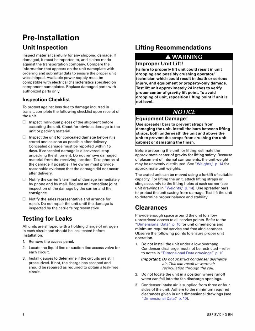
Pre-InstallationUnit InspectionInspect material carefully for any shipping damage. If
damaged, it must be reported to, and claims made
against the transportation company. Compare the
information that appears on the unit nameplate with
ordering and submittal data to ensure the proper unit
was shipped. Available power supply must be
compatible with electrical characteristics specified on
component nameplates. Replace damaged parts with
authorized parts only.
Inspection ChecklistTo protect against loss due to damage incurred in
transit, complete the following checklist upon receipt of
the unit.
Inspect individual pieces of the shipment before
accepting the unit. Check for obvious damage to the
unit or packing material.
Inspect the unit for concealed damage before it is
stored and as soon as possible after delivery.
Concealed damage must be reported within 15
days. If concealed damage is discovered, stop
unpacking the shipment. Do not remove damaged
material from the receiving location. Take photos of
the damage if possible. The owner must provide
reasonable evidence that the damage did not occur
after delivery.
Notify the carrier’s terminal of damage immediately
by phone and by mail. Request an immediate joint
inspection of the damage by the carrier and the
consignee.
Notify the sales representative and arrange for
repair. Do not repair the unit until the damage is
inspected by the carrier’s representative.
Testing for LeaksAll units are shipped with a holding charge of nitrogen
in each circuit and should be leak tested before
installation.
1. Remove the access panel.
2. Locate the liquid line or suction line access valve for
each circuit.
3. Install gauges to determine if the circuits are still
pressurized. If not, the charge has escaped and
should be repaired as required to obtain a leak-free
circuit.
Lifting Recommendations
WWAARRNNIINNGGIImmpprrooppeerr UUnniitt LLiifftt!!FFaaiilluurree ttoo pprrooppeerrllyy lliifftt uunniitt ccoouulldd rreessuulltt iinn uunniitt
ddrrooppppiinngg aanndd ppoossssiibbllyy ccrruusshhiinngg ooppeerraattoorr//
tteecchhnniicciiaann wwhhiicchh ccoouulldd rreessuulltt iinn ddeeaatthh oorr sseerriioouuss
iinnjjuurryy,, aanndd eeqquuiippmmeenntt oorr pprrooppeerrttyy--oonnllyy ddaammaaggee..
TTeesstt lliifftt uunniitt aapppprrooxxiimmaatteellyy 2244 iinncchheess ttoo vveerriiffyy
pprrooppeerr cceenntteerr ooff ggrraavviittyy lliifftt ppooiinntt.. TToo aavvooiidd
ddrrooppppiinngg ooff uunniitt,, rreeppoossiittiioonn lliiffttiinngg ppooiinntt iiff uunniitt iiss
nnoott lleevveell..
NNOOTTIICCEEEEqquuiippmmeenntt DDaammaaggee!!UUssee sspprreeaaddeerr bbaarrss ttoo pprreevveenntt ssttrraappss ffrroomm
ddaammaaggiinngg tthhee uunniitt.. IInnssttaallll tthhee bbaarrss bbeettwweeeenn lliiffttiinngg
ssttrraappss,, bbootthh uunnddeerrnneeaatthh tthhee uunniitt aanndd aabboovvee tthhee
uunniitt ttoo pprreevveenntt tthhee ssttrraappss ffrroomm ccrruusshhiinngg tthhee uunniitt
ccaabbiinneett oorr ddaammaaggiinngg tthhee ffiinniisshh..
Before preparing the unit for lifting, estimate the
approximate center of gravity for lifting safety. Because
of placement of internal components, the unit weight
may be unevenly distributed. See “Weights,” p. 14 for
approximate unit weights.
The crated unit can be moved using a forklift of suitable
capacity. For lifting the unit, attach lifting straps or
slings securely to the lifting holes at each corner (see
unit drawings in “Weights,” p. 14). Use spreader bars
to protect the unit casing from damage. Test lift the unit
to determine proper balance and stability.
ClearancesProvide enough space around the unit to allow
unrestricted access to all service points. Refer to the
“Dimensional Data,” p. 10 for unit dimensions and
minimum required service and free air clearances.
Observe the following points to ensure proper unit
operation.
1. Do not install the unit under a low overhang.
Condenser discharge must not be restricted—refer
to notes in “Dimensional Data drawings,” p. 10.
IImmppoorrttaanntt:: Do not obstruct condenser dischargeair. This can result in warm airrecirculation through the coil.
2. Do not locate the unit in a position where runoff
water can fall into the fan discharge openings.
3. Condenser intake air is supplied from three or four
sides of the unit. Adhere to the minimum required
clearances given in unit dimensional drawings (see
“Dimensional Data,” p. 10).
SSP-SVX14D-EN 9
Unit Mounting
WWAARRNNIINNGGMMoouunnttiinngg IInntteeggrriittyy!!FFaaiilluurree ttoo ffoollllooww iinnssttrruuccttiioonn bbeellooww ccoouulldd rreessuulltt iinn
ddeeaatthh oorr sseerriioouuss iinnjjuurryy oorr ppoossssiibbllee eeqquuiippmmeenntt oorr
pprrooppeerrttyy--oonnllyy ddaammaaggee..
EEnnssuurree tthhee rrooooff ssttrruuccttuurree ssuuppppoorrttss aarree ssttrroonngg
eennoouugghh ttoo ssuuppppoorrtt tthhee wweeiigghhtt ooff tthhee uunniitt aanndd aannyy
aacccceessssoorriieess..
Structural Preparation
NNOOTTIICCEERRooooff DDaammaaggee!!SSyysstteemm ccoonnttaaiinnss ooiill aanndd rreeffrriiggeerraanntt uunnddeerr hhiigghh
pprreessssuurree.. RRooooffss sshhoouulldd bbee pprrootteecctteedd ffrroomm
eexxppoossuurree ttoo ooiillss aanndd rreeffrriiggeerraanntt iinn tthhee ssyysstteemm.. IIff
rrooooffttoopp iiss nnoott pprrootteecctteedd,, ddaammaaggee ttoo tthhee rrooooff mmaayy
ooccccuurr..
IImmppoorrttaanntt:: Refer to local building codes for properinstallation. All installation must complywith local building codes.
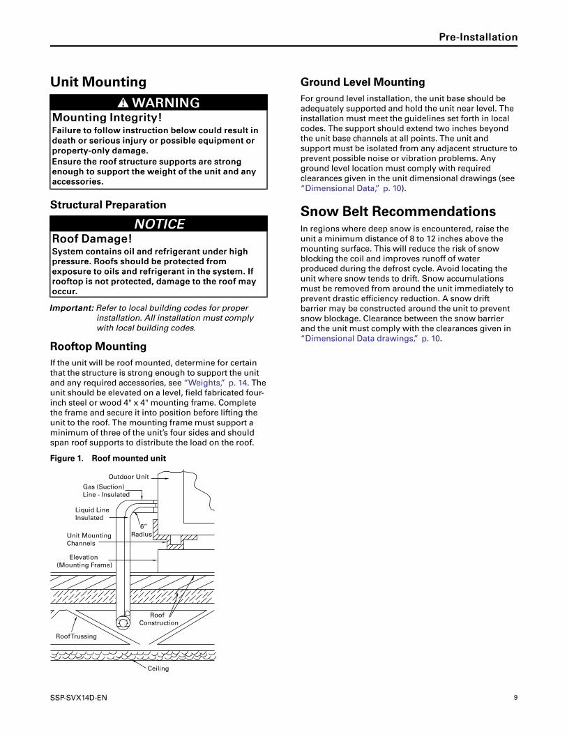
Rooftop MountingIf the unit will be roof mounted, determine for certain
that the structure is strong enough to support the unit
and any required accessories, see “Weights,” p. 14. The
unit should be elevated on a level, field fabricated four-
inch steel or wood 4" x 4" mounting frame. Complete
the frame and secure it into position before lifting the
unit to the roof. The mounting frame must support a
minimum of three of the unit’s four sides and should
span roof supports to distribute the load on the roof.
Figure 1. Roof mounted unit
Outdoor Unit
Gas (Suction)Line - Insulated
Liquid LineInsulated
Unit MountingChannels
Elevation(Mounting Frame)
Roof Trussing
Ceiling
Roof Construction
6”Radius
Ground Level MountingFor ground level installation, the unit base should be
adequately supported and hold the unit near level. The
installation must meet the guidelines set forth in local
codes. The support should extend two inches beyond
the unit base channels at all points. The unit and
support must be isolated from any adjacent structure to
prevent possible noise or vibration problems. Any
ground level location must comply with required
clearances given in the unit dimensional drawings (see
“Dimensional Data,” p. 10).
Snow Belt RecommendationsIn regions where deep snow is encountered, raise the
unit a minimum distance of 8 to 12 inches above the
mounting surface. This will reduce the risk of snow
blocking the coil and improves runoff of water
produced during the defrost cycle. Avoid locating the
unit where snow tends to drift. Snow accumulations
must be removed from around the unit immediately to
prevent drastic efficiency reduction. A snow drift
barrier may be constructed around the unit to prevent
snow blockage. Clearance between the snow barrier
and the unit must comply with the clearances given in
“Dimensional Data drawings,” p. 10.
PPrree--IInnssttaallllaattiioonn
10 SSP-SVX14D-EN
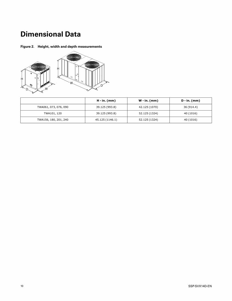
Dimensional Data
Figure 2. Height, width and depth measurements
H
WD
H
WD
H - in. (mm) W - in. (mm) D - in. (mm)
TWA061, 073, 076, 090 39.125 (993.8) 42.125 (1070) 36 (914.4)
TWA101, 120 39.125 (993.8) 52.125 (1324) 40 (1016)
TWA156, 180, 201, 240 45.125 (1146.1) 52.125 (1324) 40 (1016)
SSP-SVX14D-EN 11
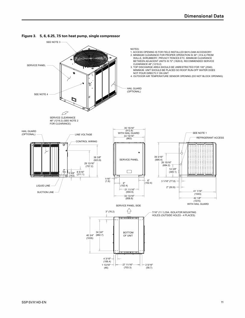
Figure 3. 5, 6, 6.25, 7.5 ton heat pump, single compressor
BOTTOMOF UNIT
14 3/8"(365.1)
26 15/16"(684.2)
39 3/16"(995.4)
3 1/16" (77.8)
2" (50.8)
33 13/16"(858.8)
1/16"(1.6)
6"(152.4)
21 11/16"(550.9)
34 3/4"(882.7)40 3/4"
(1035)
3" (76.2)
1 13/16"(46)
27 11/16"(703.3)
2 5/16"(58.7)
4 3/16"(106.4)
33 15/16"(862)
36 3/8"(923.9)
29 13/16"(757.2)
8 5/16"(211.1)5 5/8"
(143)
35 15/16"(912.8)
41 1/16"(1043)
42 1/8"(1070)
NOTES:1. ACCESS OPENING IS FOR FIELD INSTALLED BAYLOAM ACCESSORY.2. MINIMUM CLEARANCE FOR PROPER OPERATION IS 36" ( 914.4) FROM WALLS, SHRUBBERY, PRIVACY FENCES ETC. MINIMUM CLEARANCE BETWEEN ADJACENT UNITS IS 72" (1828.8). RECOMMENDED SERVICE CLEARANCE 48" (1219.2)3. TOP DISCHARGE AREA SHOULD BE UNRESTRICTED FOR 100" (2540) MINIMUM. UNIT SHOULD BE PLACED SO ROOF RUN-OFF WATER DOES NOT POUR DIRECTLY ON UNIT4. OUTDOOR AIR TEMPERATURE SENSOR OPENING (DO NOT BLOCK OPENING)
SERVICE CLEARANCE 48" (1219.2) (SEE NOTE 2FOR CLEARANCE)
SEE NOTE 1
REFRIGERANT ACCESS
HAIL GUARD (OPTIONAL)
SUCTION LINE
LIQUID LINE
CONTROL WIRING
LINE VOLTAGE
SERVICE PANEL
HAIL GUARD (OPTIONAL)
SERVICE PANEL
SEE NOTE 3
SERVICE PANEL SIDE
SEE NOTE 4
WITH HAIL GUARD
7/16" (11.1) DIA. ISOLATOR MOUNTING HOLES (OUTSIDE HOLES - 4 PLACES)
WITH HAIL GUARD
6"(152.4)
DDiimmeennssiioonnaall DDaattaa

12 SSP-SVX14D-EN
Figure 4. 8.33, 10 ton heat pump, single compressor
BOTTOMOF UNIT
51 15/16"(1319.2)
50 15/16"(1293.8)
1/16" (1.6)
2 7/8" (73)
32 7/8"(835)
44 3/4"(1136.6)
25 11/16"(652.5)
6" (152.4) 1 13/16" (46)
14 5/16"(363.5)
37 11/16"(957.3)
44 3/4"(1136.6)50 3/4"
(1289)
3" (76.2)
31 11/16"(805)
3 13/16"(96.8)
2 3/16"(55.6)
1 11/16"(42.9)
37 15/16"(963.6)
42 5/16"(1074.7)35 3/4"
(908)
1 1/4" (31.7)
8 1/4"(209.5)
5 9/16"(141.3)
4 3/8" (111.1)
4" (101.6)
4 1/4" (108) 39 15/16"(1014.4)
7/16" (11.1) DIA. ISOLATOR MOUNTING HOLES (OUTSIDE HOLES - 4 PLACES)
NOTES:1. ACCESS OPENING IS FOR FIELD INSTALLED BAYLOAM ACCESSORY.2. MINIMUM CLEARANCE FOR PROPER OPERATION IS 36" (914.4) FROM WALLS, SHRUBBERY, PRIVACY FENCES ETC. MINIMUM CLEARANCE BETWEEN ADJACENT UNITS IS 72" (1828.8). RECOMMENDED SERVICE CLEARANCE 48" (1219.2)3. TOP DISCHARGE AREA SHOULD BE UNRESTRICTED FOR 100" (2540) MINIMUM. UNIT SHOULD BE PLACED SO ROOF RUN-OFF WATER DOES NOT POUR DIRECTLY ON UNIT4. OUTDOOR AIR TEMPERATURE SENSOR OPENING (DO NOT BLOCK OPENING)
LIQUID LINE
SUCTION LINE
SERVICE PANEL SIDE
SERVICE CLEARANCE 48" (1219.2) (SEE NOTE 2FOR CLEARANCE
HAIL GUARD (OPTIONAL)
SERVICE PANEL
SEE NOTE 3
HAIL GUARD (OPTIONAL)
SERVICE PANEL
CONTROL WIRING
LINE VOLTAGEREFRIGERANT ACCESS
SEE NOTE 1
SEE NOTE 4
WITH HAIL GUARD
WITH HAIL GUARD
6" (152.4)
DDiimmeennssiioonnaall DDaattaa

SSP-SVX14D-EN 13
Figure 5. 13, 15, 16.7, 20 ton heat pump, dual compressor
BOTTOM OF UNIT
1/16"(1.6)
9"(228.6)
9"(228.6)
25 11/16"(652.5)
46"(1168.4)
93"(2362.2)
87"(2210)
41 1/2"(1054.1)
2 3/16"(55.6)
3" (76.2) 6 13/16"(173)
36 7/8"(936.6)
6 5/16" (160.3)
3 11/16" (94)
15/16" (23.8)
1 3/16" (30.2)
39 7/8"(1012.8)
41 5/8"(1057.3)
9 1/4" (235)
41 3/8"(1051)
93 5/16"(2370.1)
45 1/8"(1146.2)
14 1/2"(368.3)
14 5/8"(371.5)
12 5/8"(320.7)
5 5/8"(143)
4 1/4"(108)
6 13/16" (173)
95 7/16"(2424.112)
44 3/16"(1122.4)
LINE VOLTAGE
SUCTION LINES
REFRIGERANT ACCESS
LIQUID LINES
NOTES:1. MINIMUM CLEARANCE FOR PROPER OPERATION IS 36" (914.4) FROM WALLS, SHRUBBERY, PRIVACY FENCES ETC. MINIMUM CLEARANCE BETWEEN ADJACENT UNITS IS 72" (1829). RECOMMENDED SERVICE CLEARANCE 48" (1219.2)2. TOP DISCHARGE AREA SHOULD BE UNRESTRICTED FOR 100" (2540) MINIMUM. UNIT SHOULD BE PLACED SO ROOF RUN-OFF WATER DOES NOT POUR DIRECTLY ON UNIT3. OUTDOOR AIR TEMPERATURE SENSOR OPENING (DO NOT BLOCK OPENING).
7/16" (11.1) ( DIA. ISOLATOR MOUNTING HOLES (OUTSIDE HOLES - 4 PLACES)
SERVICE PANEL SIDE
SERVICE CLEARANCE 48" (1219.2) (SEE NOTE 1FOR CLEARANCE)
HAIL GUARD (OPTIONAL)
HAIL GUARD (OPTIONAL)
SERVICEPANEL
DIMENSIONAL DETAIL
FRONT DETAIL A
SEE NOTE 2
HAIL GUARD (OPTIONAL)
DETAIL A SERVICE PANEL
CONTROL WIRING
WITH HAIL GUARD
SEE NOTE 3
WITH HAIL GUARD
DDiimmeennssiioonnaall DDaattaa
14 SSP-SVX14D-EN
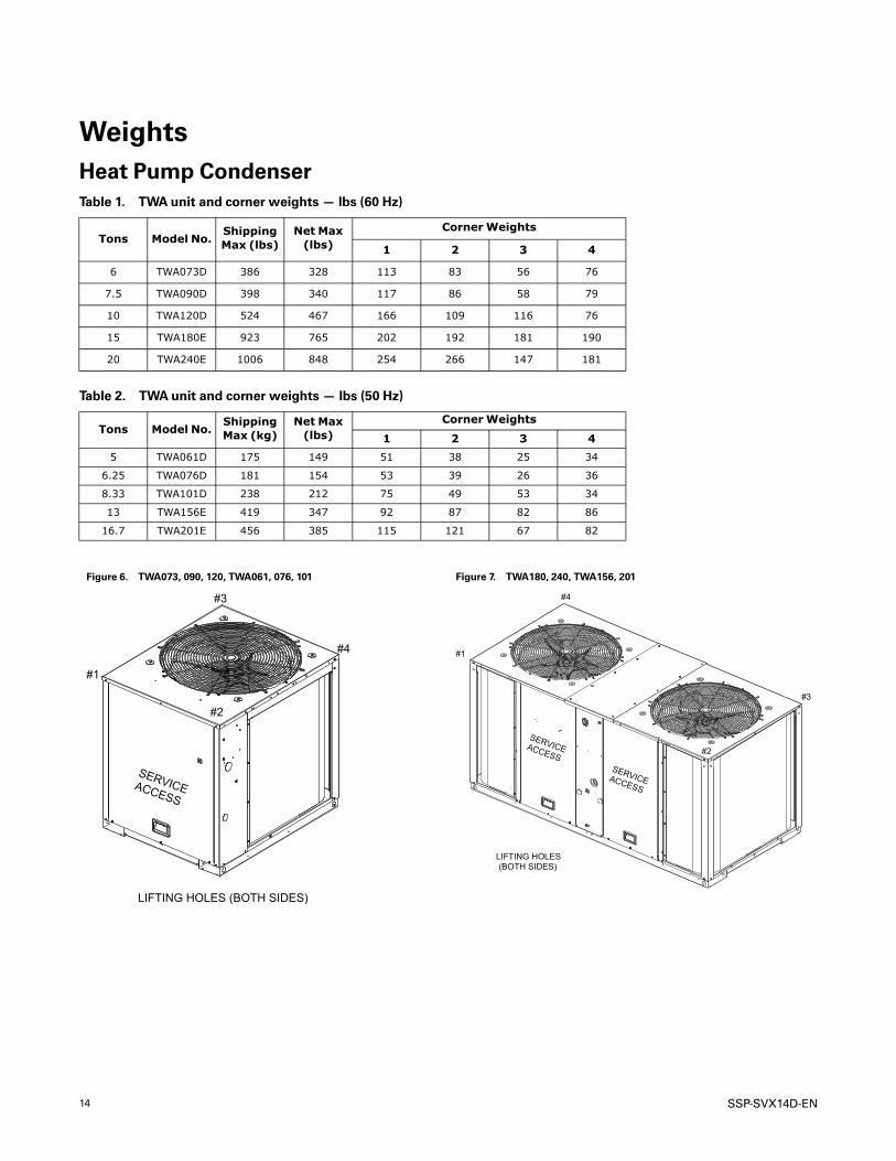
WeightsHeat Pump CondenserTable 1. TWA unit and corner weights — lbs (60 Hz)
Tons Model No.ShippingMax (lbs)
Net Max(lbs)
CornerWeights
1 2 3 4
6 TWA073D 386 328 113 83 56 76
7.5 TWA090D 398 340 117 86 58 79
10 TWA120D 524 467 166 109 116 76
15 TWA180E 923 765 202 192 181 190
20 TWA240E 1006 848 254 266 147 181
Table 2. TWA unit and corner weights — lbs (50 Hz)
Tons Model No.ShippingMax (kg)
Net Max(lbs)
CornerWeights
1 2 3 4
5 TWA061D 175 149 51 38 25 34
6.25 TWA076D 181 154 53 39 26 36
8.33 TWA101D 238 212 75 49 53 34
13 TWA156E 419 347 92 87 82 86
16.7 TWA201E 456 385 115 121 67 82
Figure 6. TWA073, 090, 120, TWA061, 076, 101
#1
#2
#3
#4
LIFTING HOLES (BOTH SIDES)
SERVICEACCESS
Figure 7. TWA180, 240, TWA156, 201
SERVICEACCESSSERVICEACCESS
#1
#2
#3
#4
LIFTING HOLES(BOTH SIDES)

SSP-SVX14D-EN 15
InstallationRefrigerant Piping GuidelinesFigure 8. Allowable elevation difference: Above indoor unit
Contact manufacturer fo r review
Acceptable suction-riser heightbased on total suction-lin e length(above indoor unit)
TTA/ TWA
indoorunit
Figure 9. Allowable elevation difference: Below indoor unit
Acceptable liquid-riser height based on total liquid-line length(below indoor unit)
Contact manufacturer for review
NNoottee:: Route refrigerant piping for minimum linear length, minimum number of bends and fittings (no reducers) andminimum amount of line exposed to outdoor ambients.
16 SSP-SVX14D-EN
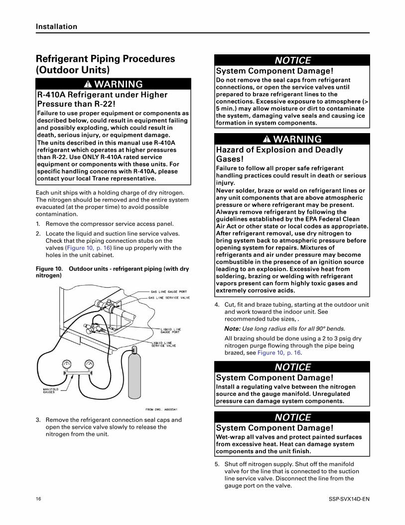
Refrigerant Piping Procedures(Outdoor Units)
WWAARRNNIINNGGRR--441100AA RReeffrriiggeerraanntt uunnddeerr HHiigghheerr
PPrreessssuurree tthhaann RR--2222!!FFaaiilluurree ttoo uussee pprrooppeerr eeqquuiippmmeenntt oorr ccoommppoonneennttss aass
ddeessccrriibbeedd bbeellooww,, ccoouulldd rreessuulltt iinn eeqquuiippmmeenntt ffaaiilliinngg
aanndd ppoossssiibbllyy eexxppllooddiinngg,, wwhhiicchh ccoouulldd rreessuulltt iinn
ddeeaatthh,, sseerriioouuss iinnjjuurryy,, oorr eeqquuiippmmeenntt ddaammaaggee..
TThhee uunniittss ddeessccrriibbeedd iinn tthhiiss mmaannuuaall uussee RR--441100AA
rreeffrriiggeerraanntt wwhhiicchh ooppeerraatteess aatt hhiigghheerr pprreessssuurreess
tthhaann RR--2222.. UUssee OONNLLYY RR--441100AA rraatteedd sseerrvviiccee
eeqquuiippmmeenntt oorr ccoommppoonneennttss wwiitthh tthheessee uunniittss.. FFoorr
ssppeecciiffiicc hhaannddlliinngg ccoonncceerrnnss wwiitthh RR--441100AA,, pplleeaassee
ccoonnttaacctt yyoouurr llooccaall TTrraannee rreepprreesseennttaattiivvee..
Each unit ships with a holding charge of dry nitrogen.
The nitrogen should be removed and the entire system
evacuated (at the proper time) to avoid possible
contamination.
1. Remove the compressor service access panel.
2. Locate the liquid and suction line service valves.
Check that the piping connection stubs on the
valves (Figure 10, p. 16) line up properly with the
holes in the unit cabinet.
Figure 10. Outdoor units - refrigerant piping (with drynitrogen)
3. Remove the refrigerant connection seal caps and
open the service valve slowly to release the
nitrogen from the unit.
NNOOTTIICCEESSyysstteemm CCoommppoonneenntt DDaammaaggee!!DDoo nnoott rreemmoovvee tthhee sseeaall ccaappss ffrroomm rreeffrriiggeerraanntt
ccoonnnneeccttiioonnss,, oorr ooppeenn tthhee sseerrvviiccee vvaallvveess uunnttiill
pprreeppaarreedd ttoo bbrraazzee rreeffrriiggeerraanntt lliinneess ttoo tthhee
ccoonnnneeccttiioonnss.. EExxcceessssiivvee eexxppoossuurree ttoo aattmmoosspphheerree ((>>
55 mmiinn..)) mmaayy aalllloowwmmooiissttuurree oorr ddiirrtt ttoo ccoonnttaammiinnaattee
tthhee ssyysstteemm,, ddaammaaggiinngg vvaallvvee sseeaallss aanndd ccaauussiinngg iiccee
ffoorrmmaattiioonn iinn ssyysstteemm ccoommppoonneennttss..
WWAARRNNIINNGGHHaazzaarrdd ooff EExxpplloossiioonn aanndd DDeeaaddllyy
GGaasseess!!FFaaiilluurree ttoo ffoollllooww aallll pprrooppeerr ssaaffee rreeffrriiggeerraanntt
hhaannddlliinngg pprraaccttiicceess ccoouulldd rreessuulltt iinn ddeeaatthh oorr sseerriioouuss
iinnjjuurryy..
NNeevveerr ssoollddeerr,, bbrraazzee oorr wweelldd oonn rreeffrriiggeerraanntt lliinneess oorr
aannyy uunniitt ccoommppoonneennttss tthhaatt aarree aabboovvee aattmmoosspphheerriicc
pprreessssuurree oorr wwhheerree rreeffrriiggeerraanntt mmaayy bbee pprreesseenntt..
AAllwwaayyss rreemmoovvee rreeffrriiggeerraanntt bbyy ffoolllloowwiinngg tthhee
gguuiiddeelliinneess eessttaabblliisshheedd bbyy tthhee EEPPAA FFeeddeerraall CClleeaann
AAiirr AAcctt oorr ootthheerr ssttaattee oorr llooccaall ccooddeess aass aapppprroopprriiaattee..
AAfftteerr rreeffrriiggeerraanntt rreemmoovvaall,, uussee ddrryy nniittrrooggeenn ttoo
bbrriinngg ssyysstteemm bbaacckk ttoo aattmmoosspphheerriicc pprreessssuurree bbeeffoorree
ooppeenniinngg ssyysstteemm ffoorr rreeppaaiirrss.. MMiixxttuurreess ooff
rreeffrriiggeerraannttss aanndd aaiirr uunnddeerr pprreessssuurree mmaayy bbeeccoommee
ccoommbbuussttiibbllee iinn tthhee pprreesseennccee ooff aann iiggnniittiioonn ssoouurrccee
lleeaaddiinngg ttoo aann eexxpplloossiioonn.. EExxcceessssiivvee hheeaatt ffrroomm
ssoollddeerriinngg,, bbrraazziinngg oorr wweellddiinngg wwiitthh rreeffrriiggeerraanntt
vvaappoorrss pprreesseenntt ccaann ffoorrmm hhiigghhllyy ttooxxiicc ggaasseess aanndd
eexxttrreemmeellyy ccoorrrroossiivvee aacciiddss..
4. Cut, fit and braze tubing, starting at the outdoor unit
and work toward the indoor unit. See
recommended tube sizes, .
NNoottee:: Use long radius ells for all 90° bends.
All brazing should be done using a 2 to 3 psig dry
nitrogen purge flowing through the pipe being
brazed, see Figure 10, p. 16.
NNOOTTIICCEESSyysstteemm CCoommppoonneenntt DDaammaaggee!!IInnssttaallll aa rreegguullaattiinngg vvaallvvee bbeettwweeeenn tthhee nniittrrooggeenn
ssoouurrccee aanndd tthhee ggaauuggee mmaanniiffoolldd.. UUnnrreegguullaatteedd
pprreessssuurree ccaann ddaammaaggee ssyysstteemm ccoommppoonneennttss..
NNOOTTIICCEESSyysstteemm CCoommppoonneenntt DDaammaaggee!!WWeett--wwrraapp aallll vvaallvveess aanndd pprrootteecctt ppaaiinntteedd ssuurrffaacceess
ffrroomm eexxcceessssiivvee hheeaatt.. HHeeaatt ccaann ddaammaaggee ssyysstteemm
ccoommppoonneennttss aanndd tthhee uunniitt ffiinniisshh..
5. Shut off nitrogen supply. Shut off the manifold
valve for the line that is connected to the suction
line service valve. Disconnect the line from the
gauge port on the valve.
IInnssttaallllaattiioonn

SSP-SVX14D-EN 17
Refrigerant Piping Procedures(Indoor Unit)Once liquid and suction lines are complete to the
refrigerant connections on the indoor unit, remove the
gauge port core(s) on the indoor unit connection stubs
to release the dry nitrogen charge.
NNOOTTIICCEEUUnniitt DDaammaaggee!!DDoo nnoott aappppllyy hheeaatt ttoo rreemmoovvee sseeaall ccaappss uunnttiill tthhee
ggaauuggee ppoorrtt ccoorreess hhaavvee bbeeeenn rreemmoovveedd.. IIff sseeaall ccaappss
aarree iinnttaacctt,, aapppplliiccaattiioonn ooff hheeaatt mmaayy ggeenneerraattee
eexxcceessssiivvee pprreessssuurree iinn tthhee uunniitt aanndd rreessuulltt iinn
ddaammaaggee ttoo tthhee ccooiill oorr eexxppaannssiioonn vvaallvvee..
1. Remove both seal caps from the indoor unit
connection stubs.
NNOOTTIICCEEUUnniitt DDaammaaggee!!DDoo nnoott rreemmoovvee tthhee sseeaall ccaappss ffrroomm rreeffrriiggeerraanntt
ccoonnnneeccttiioonnss,, oorr ooppeenn tthhee sseerrvviiccee vvaallvveess uunnttiill
pprreeppaarreedd ttoo bbrraazzee rreeffrriiggeerraanntt lliinneess ttoo tthhee
ccoonnnneeccttiioonnss.. DDuuee ttoo tthhee hhiigghh hhyyggrroossccooppiicc
pprrooppeerrttiieess ooff tthhee RR--441100AA ooiill,, eexxcceessssiivvee eexxppoossuurree ttoo
aattmmoosspphheerree wwiillll aalllloowwmmooiissttuurree ttoo ccoonnttaammiinnaattee
tthhee ssyysstteemm,, ddaammaaggiinngg tthhee ccoommpprreessssoorr..
2. Turn on nitrogen supply. Nitrogen enters through
the liquid line gauge port.
3. Braze the liquid line connections.
4. Open the gauge port on the suction line and then
braze the suction line to the connection stub.
Nitrogen will bleed out the open gauge port on the
suction line.
5. Shut off nitrogen supply.
Leak CheckWWAARRNNIINNGG
HHaazzaarrdd ooff EExxpplloossiioonn!!FFaaiilluurree ttoo ffoollllooww tthheessee rreeccoommmmeennddaattiioonnss ccoouulldd
rreessuulltt iinn ddeeaatthh oorr sseerriioouuss iinnjjuurryy oorr eeqquuiippmmeenntt oorr
pprrooppeerrttyy--oonnllyy ddaammaaggee..
UUssee oonnllyy ddrryy nniittrrooggeenn wwiitthh aa pprreessssuurree rreegguullaattoorr ffoorr
pprreessssuurriizziinngg uunniitt.. DDoo nnoott uussee aacceettyylleennee,, ooxxyyggeenn oorr
ccoommpprreesssseedd aaiirr oorr mmiixxttuurreess ccoonnttaaiinniinngg tthheemm ffoorr
pprreessssuurree tteessttiinngg.. DDoo nnoott uussee mmiixxttuurreess ooff aa
hhyyddrrooggeenn ccoonnttaaiinniinngg rreeffrriiggeerraanntt aanndd aaiirr aabboovvee
aattmmoosspphheerriicc pprreessssuurree ffoorr pprreessssuurree tteessttiinngg aass tthheeyy
mmaayy bbeeccoommee ffllaammmmaabbllee aanndd ccoouulldd rreessuulltt iinn aann
eexxpplloossiioonn.. RReeffrriiggeerraanntt,, wwhheenn uusseedd aass aa ttrraaccee ggaass
sshhoouulldd oonnllyy bbee mmiixxeedd wwiitthh ddrryy nniittrrooggeenn ffoorr
pprreessssuurriizziinngg uunniittss..
WWAARRNNIINNGGHHaazzaarrdd ooff EExxpplloossiioonn!!FFaaiilluurree ttoo ffoollllooww rreeccoommmmeennddeedd ssaaffee lleeaakk tteesstt
pprroocceedduurreess ccoouulldd rreessuulltt iinn ddeeaatthh oorr sseerriioouuss iinnjjuurryy
oorr eeqquuiippmmeenntt oorr pprrooppeerrttyy--oonnllyy--ddaammaaggee..
NNeevveerr uussee aann ooppeenn ffllaammee ttoo ddeetteecctt ggaass lleeaakkss.. UUssee aa
lleeaakk tteesstt ssoolluuttiioonn ffoorr lleeaakk tteessttiinngg..
After the brazing operation of refrigerant lines to both
the outdoor and indoor unit is completed, the field
brazed connections must be checked for leaks.
Pressurize the system through the service valve with
dry nitrogen to 200 psi. Use soap bubbles or other leak-
checking methods to ensure that all field joints are leak
free. If not, release pressure, repair and repeat leak test.
System Evacuation1. After completion of leak check, evacuate the
system.
2. Attach appropriate hoses from manifold gauge to
gas and liquid line pressure taps.
NNoottee:: Unnecessary switching of hoses can beavoided and complete evacuation of all linesleading to sealed system can beaccomplished with manifold center hose andconnecting branch hose to a cylinder of R-410A and vacuum pump.
3. Attach center hose of manifold gauges to vacuum
pump.
NNOOTTIICCEEOOppeerraattiinngg UUnnddeerr VVaaccuuuumm!!FFaaiilluurree ttoo ffoollllooww tthheessee iinnssttrruuccttiioonnss wwiillll rreessuulltt iinn
ccoommpprreessssoorr ffaaiilluurree..
DDoo nnoott ooppeerraattee oorr aappppllyy ppoowweerr ttoo tthhee ccoommpprreessssoorr
wwhhiillee uunnddeerr aa vvaaccuuuumm..
4. Evacuate the system to hold a 500 micron vacuum.
5. Close off valve to vacuum pump and observe the
micron gauge. If gauge pressure rises above 500
microns in one minute, then evacuation is
incomplete or the system has a leak.
6. If vacuum gauge does not rise above 500 microns in
10 minutes, the evacuation should be complete.
NNOOTTIICCEEEEqquuiippmmeenntt DDaammaaggee!!CChhaarrggee wwiitthh aacccceessss ppoorrtt oonn tthhee lliiqquuiidd lliinnee sseerrvviiccee
vvaallvvee oonnllyy..
7. With vacuum pump and micron gauge blanked off,
open valve on R-410A cylinder and allow refrigerant
pressure to build up to about 80 psig.
8. Close valve on the R-410A supply cylinder. Close
valves on manifold gauge set and remove
IInnssttaallllaattiioonn
18 SSP-SVX14D-EN
refrigerant charging hoses from liquid and gas
gauge ports.
9. Leak test the entire system. Using proper
procedures and caution, as described in the
previous section, repair any leaks found and repeat
the leak test.
Insulating and IsolatingRefrigerant LinesInsulate the entire suction line with refrigerant piping
insulation. Also insulate any portion of the liquid line
exposed to temperature extremes. Insulate and isolate
liquid and suction lines from each other. Isolate
refrigerant lines from the structure and any duct work.
IImmppoorrttaanntt::
1. To prevent possible noise or vibrationproblems, be certain to isolaterefrigerant lines from the building.
2. All suction and hot gas bypass piping (ifinstalled) should be insulated from thetermination in the air handler to thecondensing unit cabinet entry. Failure todo so can cause condensate drip off andperformance degradation.
3. Prior to starting a unit, it is advisable tohave the approved oils available in theevent oil needs to be added to thesystem.
NNOOTTIICCEEEEqquuiippmmeenntt DDaammaaggee!!TThhiiss iiss PPOOEE ooiill,, wwhhiicchh rreeaaddiillyy aabbssoorrbbss mmooiissttuurree..
AAllwwaayyss uussee nneeww ooiill aanndd nneevveerr lleeaavvee ccoonnttaaiinneerrss
ooppeenn ttoo aattmmoosspphheerree wwhhiillee nnoott iinn uussee..
Table 3. TWA approved oils
Unit Model Number Approved Oils
TWA061, TWA073, TWA076,TWA090, TWA101, TWA120,TWA156, TWA180, TWA201,
TWA240
Trane Oil Part Number OIL00094(1 quart container)
For units equipped with compressors containing site
glasses, the oil level must be visible through the sight
glass when the compressor is running under stabilized
conditions and a few minutes after the compressor has
stopped.
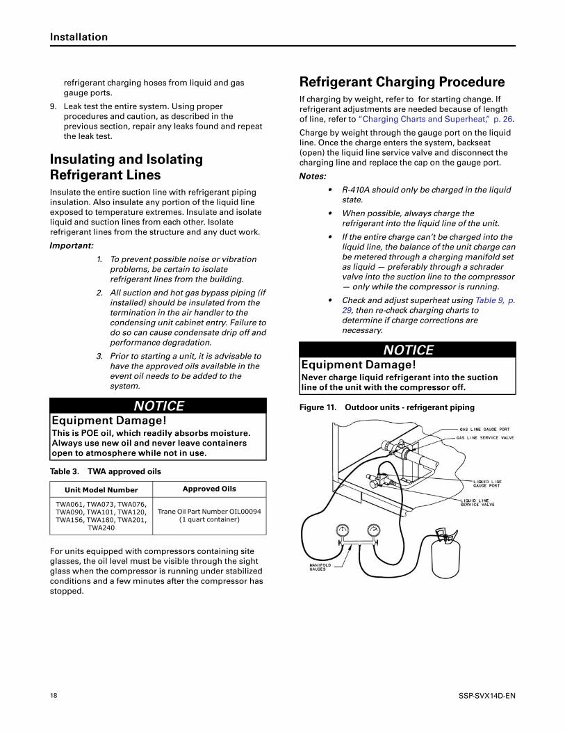
Refrigerant Charging ProcedureIf charging by weight, refer to for starting change. If
refrigerant adjustments are needed because of length
of line, refer to “Charging Charts and Superheat,” p. 26.
Charge by weight through the gauge port on the liquid
line. Once the charge enters the system, backseat
(open) the liquid line service valve and disconnect the
charging line and replace the cap on the gauge port.
NNootteess::
• R-410A should only be charged in the liquidstate.
• When possible, always charge therefrigerant into the liquid line of the unit.
• If the entire charge can’t be charged into theliquid line, the balance of the unit charge canbe metered through a charging manifold setas liquid — preferably through a schradervalve into the suction line to the compressor— only while the compressor is running.
• Check and adjust superheat using Table 9, p.29, then re-check charging charts todetermine if charge corrections arenecessary.
NNOOTTIICCEEEEqquuiippmmeenntt DDaammaaggee!!NNeevveerr cchhaarrggee lliiqquuiidd rreeffrriiggeerraanntt iinnttoo tthhee ssuuccttiioonn
lliinnee ooff tthhee uunniitt wwiitthh tthhee ccoommpprreessssoorr ooffff..
Figure 11. Outdoor units - refrigerant piping
IInnssttaallllaattiioonn

SSP-SVX14D-EN 19
Charging Levels
Table 4. Estimated charge levels at ARI rated line lengths (25 feet)
Matched Set
Refrigerant Charge Per Circuit
Circuit 1 Circuit 2Liquid LineDiameter
Vapor LineDiameter
TWA061D w/TWE076D(a) 20.4 NA 0.5 (1/2”) 1.125 (1 1/8”)
TWA073D w/TWE090D 20.4 NA 0.5 (1/2”) 1.125 (1 1/8”)
TWA076D w/TWE076D 20.6 NA 0.625 (5/8”) 1.375 (1 3/8”)
TWA090D w/TWE090D 20.6 NA 0.625 (5/8”) 1.375 (1 3/8”)
TWA101D w/TWE101D 28.0 NA 0.5 (1/2”) 1.375 (1 3/8”)
TWA120D w/TWE120D 28.0 NA 0.5 (1/2”) 1.375 (1 3/8”)
TWA156E w/TWE156E 22.9 24.2 0.5 (1/2”) 1.375 (1 3/8”)
TWA180E w/TWE180E 22.9 24.2 0.5 (1/2”) 1.375 (1 3/8”)
TWA201E w/TWE201E 23.5 23.5 0.625 (5/8”) 1.375 (1 3/8”)
TWA240E w/TWE240E 23.5 23.5 0.625 (5/8”) 1.375 (1 3/8”)
(a) TWA061D and TWA073D need a reducer for vapor line. (1.375 to 1.125) (1 3/8” to 1 1/8”)
Liquid ChargingThis procedure is accomplished with the unit
operating. Electrical connections must be complete. Do
not proceed until the system is ready to operate.
NNoottee:: The compressor access panel must be installedwhen the unit is running and being charged.Manifold hoses must be routed throughrefrigerant gauge access hole(s). See“Dimensional Data,” p. 10 for specific locations.
WWAARRNNIINNGGLLiivvee EElleeccttrriiccaall CCoommppoonneennttss!!FFaaiilluurree ttoo ffoollllooww aallll eelleeccttrriiccaall ssaaffeettyy pprreeccaauuttiioonnss
wwhheenn eexxppoosseedd ttoo lliivvee eelleeccttrriiccaall ccoommppoonneennttss ccoouulldd
rreessuulltt iinn ddeeaatthh oorr sseerriioouuss iinnjjuurryy..
WWhheenn iitt iiss nneecceessssaarryy ttoo wwoorrkk wwiitthh lliivvee eelleeccttrriiccaall
ccoommppoonneennttss,, hhaavvee aa qquuaalliiffiieedd lliicceennsseedd eelleeccttrriicciiaann
oorr ootthheerr iinnddiivviidduuaall wwhhoo hhaass bbeeeenn pprrooppeerrllyy ttrraaiinneedd
iinn hhaannddlliinngg lliivvee eelleeccttrriiccaall ccoommppoonneennttss ppeerrffoorrmm
tthheessee ttaasskkss..
1. Turn on power to the unit. Allow the system to run
for 15 minutes to stabilize operating conditions.
2. Measure airflow across the indoor coil. Compare
the measurements with the fan performance data in
the Data/Submittal or Service Facts. Once proper
airflow is established, compare discharge pressure
and liquid temperature to the “Charging Charts,” p.
26. Add or remove refrigerant (liquid only) as
required to obtain correct discharge pressure and
liquid temperature.
3. Check suction line superheat and condenser sub-
cooling to ensure the unit is operating properly.
4. Disconnect all power to the unit.
IImmppoorrttaanntt:: If the unit is charged and left withoutpower until a later date, the crankcaseheater should be energized for aminimum of 8 hours prior to poweringthe compressor(s).
WWAARRNNIINNGGHHaazzaarrddoouuss VVoollttaaggee ww//CCaappaacciittoorrss!!FFaaiilluurree ttoo ddiissccoonnnneecctt ppoowweerr aanndd ddiisscchhaarrggee
ccaappaacciittoorrss bbeeffoorree sseerrvviicciinngg ccoouulldd rreessuulltt iinn ddeeaatthh oorr
sseerriioouuss iinnjjuurryy..
DDiissccoonnnneecctt aallll eelleeccttrriicc ppoowweerr,, iinncclluuddiinngg rreemmoottee
ddiissccoonnnneeccttss aanndd ddiisscchhaarrggee aallll mmoottoorr ssttaarrtt//rruunn
ccaappaacciittoorrss bbeeffoorree sseerrvviicciinngg.. FFoollllooww pprrooppeerr lloocckkoouutt//
ttaaggoouutt pprroocceedduurreess ttoo eennssuurree tthhee ppoowweerr ccaannnnoott bbee
iinnaaddvveerrtteennttllyy eenneerrggiizzeedd.. FFoorr vvaarriiaabbllee ffrreeqquueennccyy
ddrriivveess oorr ootthheerr eenneerrggyy ssttoorriinngg ccoommppoonneennttss
pprroovviiddeedd bbyy TTrraannee oorr ootthheerrss,, rreeffeerr ttoo tthhee
aapppprroopprriiaattee mmaannuuffaaccttuurreerr’’ss lliitteerraattuurree ffoorr
aalllloowwaabbllee wwaaiittiinngg ppeerriiooddss ffoorr ddiisscchhaarrggee ooff
ccaappaacciittoorrss.. VVeerriiffyy wwiitthh aann aapppprroopprriiaattee vvoollttmmeetteerr
tthhaatt aallll ccaappaacciittoorrss hhaavvee ddiisscchhaarrggeedd..
FFoorr aaddddiittiioonnaall iinnffoorrmmaattiioonn rreeggaarrddiinngg tthhee ssaaffeeddiisscchhaarrggee ooff ccaappaacciittoorrss,, sseeee PPRROODD--SSVVBB0066AA--EENN..
5. Remove the charging system from the unit.
6. Replace all panels.
IInnssttaallllaattiioonn
20 SSP-SVX14D-EN
Electrical Wiring
WWAARRNNIINNGGPPrrooppeerr FFiieelldd WWiirriinngg aanndd GGrroouunnddiinngg
RReeqquuiirreedd!!FFaaiilluurree ttoo ffoollllooww ccooddee ccoouulldd rreessuulltt iinn ddeeaatthh oorr
sseerriioouuss iinnjjuurryy..
AAllll ffiieelldd wwiirriinngg MMUUSSTT bbee ppeerrffoorrmmeedd bbyy qquuaalliiffiieedd
ppeerrssoonnnneell.. IImmpprrooppeerrllyy iinnssttaalllleedd aanndd ggrroouunnddeedd
ffiieelldd wwiirriinngg ppoosseess FFIIRREE aanndd EELLEECCTTRROOCCUUTTIIOONN
hhaazzaarrddss.. TToo aavvooiidd tthheessee hhaazzaarrddss,, yyoouu MMUUSSTT ffoollllooww
rreeqquuiirreemmeennttss ffoorr ffiieelldd wwiirriinngg iinnssttaallllaattiioonn aanndd
ggrroouunnddiinngg aass ddeessccrriibbeedd iinn NNEECC aanndd yyoouurr llooccaall//
ssttaattee eelleeccttrriiccaall ccooddeess..
Field wiring consists of providing power supply to the
unit, installing the system indoor thermostat and
providing low voltage system interconnecting wiring.
Access to electrical connection locations is shown in
“Dimensional Data,” p. 10. Determine proper wire sizes
and unit protective fusing requirements by referring to
the unit nameplate and/or the unit Service Facts. Field
wiring diagrams for accessories are shipped with the
accessory.
Unit Power SupplyThe installer must provide line voltage circuit(s) to the
unit main power terminals as shown by the unit wiring
diagrams (available through e-Library or by contacting
a local sales office) or field wiring. Power supply must
include a disconnect switch in a location convenient to
the unit. Ground the unit according to local codes and
provide flexible conduit if codes require and/or if
vibration transmission may cause noise problems.
IImmppoorrttaanntt:: All wiring must comply with applicablelocal and national (NEC) codes. Type andlocation of disconnect switches mustcomply with all applicable codes.
WWAARRNNIINNGGPPrrooppeerr FFiieelldd WWiirriinngg aanndd GGrroouunnddiinngg
RReeqquuiirreedd!!FFaaiilluurree ttoo ffoollllooww ccooddee ccoouulldd rreessuulltt iinn ddeeaatthh oorr
sseerriioouuss iinnjjuurryy..
AAllll ffiieelldd wwiirriinngg MMUUSSTT bbee ppeerrffoorrmmeedd bbyy qquuaalliiffiieedd
ppeerrssoonnnneell.. IImmpprrooppeerrllyy iinnssttaalllleedd aanndd ggrroouunnddeedd
ffiieelldd wwiirriinngg ppoosseess FFIIRREE aanndd EELLEECCTTRROOCCUUTTIIOONN
hhaazzaarrddss.. TToo aavvooiidd tthheessee hhaazzaarrddss,, yyoouu MMUUSSTT ffoollllooww
rreeqquuiirreemmeennttss ffoorr ffiieelldd wwiirriinngg iinnssttaallllaattiioonn aanndd
ggrroouunnddiinngg aass ddeessccrriibbeedd iinn NNEECC aanndd yyoouurr llooccaall//
ssttaattee eelleeccttrriiccaall ccooddeess..
NNOOTTIICCEEUUssee CCooppppeerr CCoonndduuccttoorrss OOnnllyy!!FFaaiilluurree ttoo uussee ccooppppeerr ccoonndduuccttoorrss ccoouulldd rreessuulltt iinn
eeqquuiippmmeenntt ddaammaaggee aass uunniitt tteerrmmiinnaallss aarree nnoott
ddeessiiggnneedd ttoo aacccceepptt ootthheerr ttyyppeess ooff ccoonndduuccttoorrss..
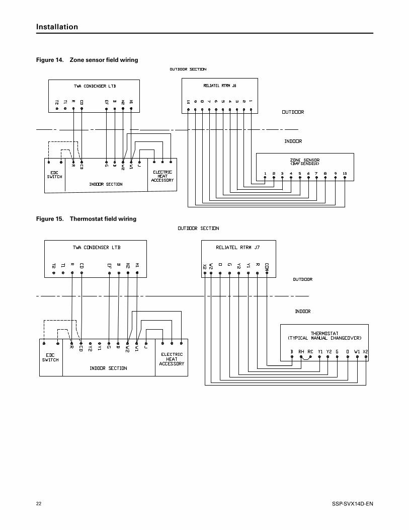
Low Voltage WiringMount the indoor thermostat, zone sensor, or Night
Setback Panel (NSB) in accordance with the
corresponding thermostat installation instructions.
Install color-coded, weather-proof, multi-wire cable
according to the field wiring schematics (see “Field
Wiring,” p. 21).
ReliaTel ControlsWiring shown with dashed lines is to be furnished and
installed by the customer. All customer supplied wiring
must be copper only and must conform to NEC and
local electrical codes. Codes may require line of sight
between disconnect switch and unit.
NNootteess::
1. When electric heater accessory is used,single point power entry or dual point powerentry is field optional. Single point powerentry option is through electric heater only.
2. ***Choose only one of the following;Thermostat, Zone Sensor, or NSB Panel.
IImmppoorrttaanntt:: For the EDC switch to be functional andthereby facilitate reliable unit operation,make the EDC connections from the indoorto the outdoor control boxes.
IInnssttaallllaattiioonn
SSP-SVX14D-EN 21
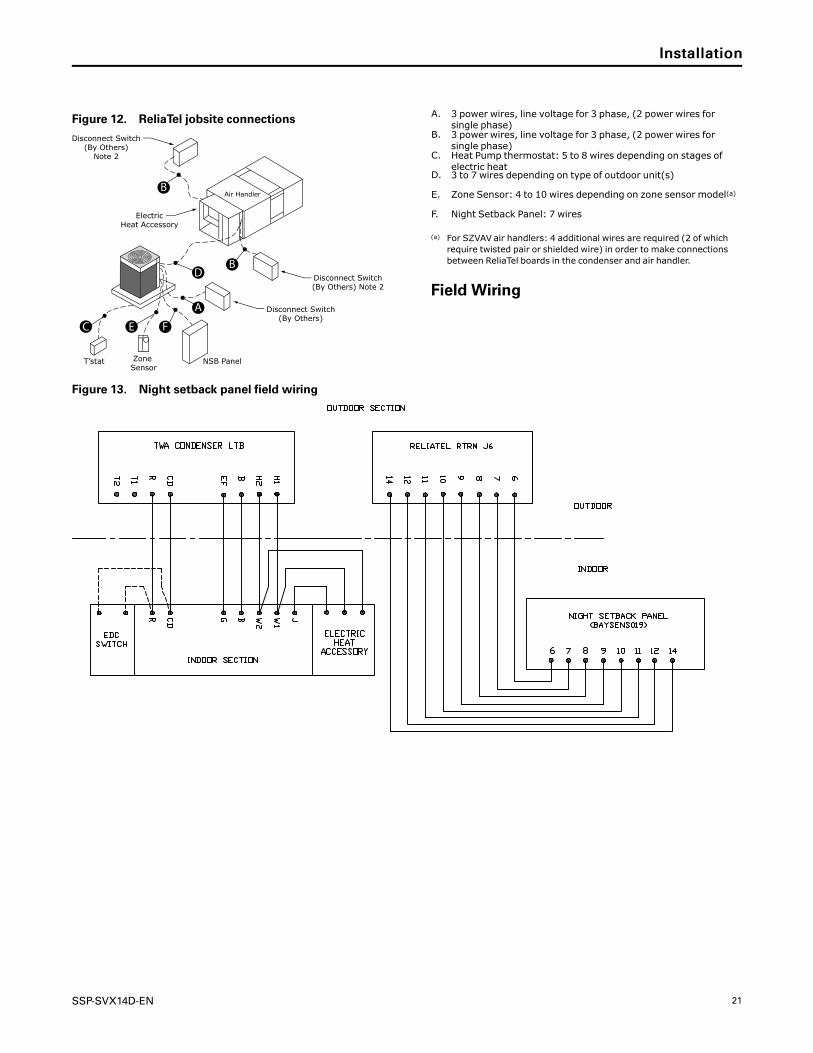
Figure 12. ReliaTel jobsite connections
NSB PanelZone Sensor
T’stat
Air Handler
Disconnect S witch(By Others)
Disconnect S witch(By Others) Note 2
ElectricHeat Accessory
Disconnect S witch(By Others)
Note 2
B
A
B
D
FEC
A. 3 power wires, line voltage for 3 phase, (2 power wires forsingle phase)
B. 3 power wires, line voltage for 3 phase, (2 power wires forsingle phase)
C. Heat Pump thermostat: 5 to 8 wires depending on stages ofelectric heat
D. 3 to 7 wires depending on type of outdoor unit(s)
E. Zone Sensor: 4 to 10 wires depending on zone sensor model(a)
F. Night Setback Panel: 7 wires
(a) For SZVAV air handlers: 4 additional wires are required (2 of whichrequire twisted pair or shielded wire) in order to make connectionsbetween ReliaTel boards in the condenser and air handler.
Field Wiring
Figure 13. Night setback panel field wiring
IInnssttaallllaattiioonn
22 SSP-SVX14D-EN
Figure 14. Zone sensor field wiring
Figure 15. Thermostat field wiring
X
X
IInnssttaallllaattiioonn
SSP-SVX14D-EN 23
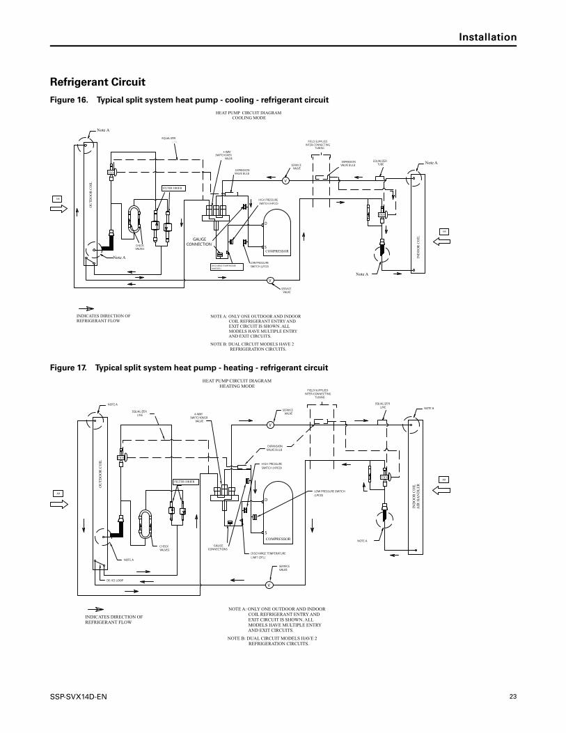
Refrigerant Circuit
Figure 16. Typical split system heat pump - cooling - refrigerant circuit
Note A
Note A
S
D
COMPRESSOR
Note A
OU
TD
OO
R C
OIL
IND
OO
R C
OIL
AIR
AIR
TXV
Note A
FILTER DRIER
TXV
FIELD SUPPLIEDINTER-CONNECTING
TUBING
EQUALIZERTUBE
EXPANSIONVALVE BULB
CHECKVALVES
GAUGECONNECTION
HIGH PRESSURESWITCH (HPCO)
DISCHARGE TEMPERATURELIMIT(DTL)
LOW PRESSURESWITCH (LPCO)
SERVICEVALVE
SERVICEVALVE
EXPANSIONVALVE BULB
4-WAYSWITCHOVER
VALVE
EQUALIZERLINE
NOTE A: ONLY ONE OUTDOOR AND INDOOR COIL REFRIGERANT ENTRY AND EXIT CIRCUIT IS SHOWN. ALL MODELS HAVE MULTIPLE ENTRY AND EXIT CIRCUITS.
HEAT PUMP CIRCUIT DIAGRAMCOOLING MODE
INDICATES DIRECTION OFREFRIGERANT FLOW
NOTE B: DUAL CIRCUIT MODELS HAVE 2 REFRIGERATION CIRCUITS.
V
V
Figure 17. Typical split system heat pump - heating - refrigerant circuit
NOTE A
TXV
S
D
COMPRESSOR
NOTE A
NOTE A
FIELD SUPPLIEDINTER-CONNECTING
TUBING
EQUALIZERLINE
OU
TD
OO
R C
OIL
IND
OO
R C
OIL
AIR
HA
ND
LE
R
AIR
AIR
TXV
SERVICEVALVE
EXPANSIONVALVE BULB
SERVICEVALVE
GAUGECONNECTIONS
DISCHARGE TEMPERATURELIMIT (DTL)
HIGH PRESSURESWITCH (HPCO)
DE-ICE LOOP
NOTE A
CHECKVALVES
4-WAYSWITCHOVER
VALVE
LOW PRESSURE SWITCH(LPCO)
EQUALIZERLINE
NOTE A: ONLY ONE OUTDOOR AND INDOOR COIL REFRIGERANT ENTRY AND EXIT CIRCUIT IS SHOWN. ALL MODELS HAVE MULTIPLE ENTRY AND EXIT CIRCUITS.
INDICATES DIRECTION OFREFRIGERANT FLOW
HEAT PUMP CIRCUIT DIAGRAMHEATING MODE
NOTE B: DUAL CIRCUIT MODELS HAVE 2 REFRIGERATION CIRCUITS.
V
V
FILTER DRIER
IInnssttaallllaattiioonn

24 SSP-SVX14D-EN
Electrical Data
Table 5. Electrical characteristics — compressor and condenser fan motors — heat pumps — 60 Hz
TonsUnitModelNumber
Compressor Motor Condenser Fan Motor
No. Volts Phase
Amps
No. Volts Phase
Amps
RLA LRA FLA LRA
(Ea.) (Ea.) (Ea.) (Ea.)
6
TWA073D3 1 208-230 3 22.4 149 1 208-230 1 3.1 8.1
TWA073D4 1 460 3 10.6 75 1 460 1 1.6 3.8
TWA073DK 1 380 3 11.3 88 1 380 1 1.9 4.9
TWA073DW 1 575 3 8.3 54 1 575 1 1.2 3
7.5
TWA090D3 1 208-230 3 25 164 1 208-230 1 3.1 8.1
TWA090D4 1 460 3 13 100 1 460 1 1.6 3.8
TWA090DK 1 380 3 13.9 94.3 1 380 1 1.9 4.9
TWA090DW 1 575 3 10.8 78 1 575 1 1.2 3
10
TWA120D3 1 208-230 3 33 267 1 208-230 1 5 14.4
TWA120D4 1 460 3 17.8 142 1 460 1 2.5 5.8
TWA120DK 1 380 3 25.1 160 1 380 1 3.4 7.8
TWA120DW 1 575 3 15.8 103 1 575 1 2 5.1
15
TWA180E3 2 208-230 3 25 164 2 208-230 1 5 14.4
TWA180E4 2 460 3 12.6 100 2 460 1 2.5 5.8
TWA180EK 2 380 3 14.3 94.3 2 380 1 3.4 7.8
TWA180EW 2 575 3 10.4 78 2 575 1 2 5.1
20
TWA240E3 2 208-230 3 33.8 239 2 208-230 1 5 14.4
TWA240E4 2 460 3 18 125 2 460 1 2.5 5.8
TWA240EK 2 380 3 24.4 145 2 380 1 3.4 7.8
TWA240EW 2 575 3 13.7 80 2 575 1 2 5.1
Table 6. Unit wiring — heat pumps — 60 Hz
Tons Unit Model NumberUnit OperatingVoltage Range
Minimum CircuitAmpacity
Maximum Fuse orHACR CircuitBreaker Size
6
TWA073D3 187-253 31.1 40
TWA073D4 414-506 14.9 20
TWA073DK 342-418 17.0 25
TWA073DW 518-632 11.6 15
7.5
TWA090D3 187-253 34.4 45
TWA090D4 414-506 17.9 25
TWA090DK 342-418 20.0 30
TWA090DW 518-632 14.7 20
10
TWA120D3 187-253 47.0 70
TWA120D4 414-506 25.0 40
TWA120DK 342-418 35.0 50
TWA120DW 518-632 22.0 35
15
TWA180E3 187-253 66.3 80
TWA180E4 414-506 33.4 40
TWA180EK 342-418 39.0 45
TWA180EW 518-632 27.4 30
SSP-SVX14D-EN 25
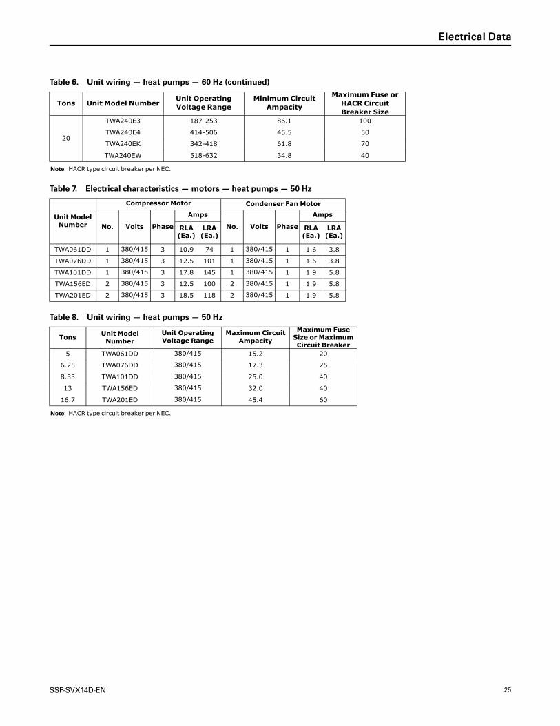
Table 6. Unit wiring — heat pumps — 60 Hz (continued)
Tons Unit Model NumberUnit OperatingVoltage Range
Minimum CircuitAmpacity
Maximum Fuse orHACR CircuitBreaker Size
20
TWA240E3 187-253 86.1 100
TWA240E4 414-506 45.5 50
TWA240EK 342-418 61.8 70
TWA240EW 518-632 34.8 40
Note: HACR type circuit breaker per NEC.
Table 7. Electrical characteristics — motors — heat pumps — 50 Hz
Unit ModelNumber
Compressor Motor Condenser Fan Motor
No. Volts Phase
Amps
No. Volts Phase
Amps
RLA(Ea.)
LRA(Ea.)
RLA(Ea.)
LRA(Ea.)
TWA061DD 1 380/415 3 10.9 74 1 380/415 1 1.6 3.8
TWA076DD 1 380/415 3 12.5 101 1 380/415 1 1.6 3.8
TWA101DD 1 380/415 3 17.8 145 1 380/415 1 1.9 5.8
TWA156ED 2 380/415 3 12.5 100 2 380/415 1 1.9 5.8
TWA201ED 2 380/415 3 18.5 118 2 380/415 1 1.9 5.8
Table 8. Unit wiring — heat pumps — 50 Hz
Tons Unit ModelNumber
Unit OperatingVoltage Range
Maximum CircuitAmpacity
Maximum FuseSize or MaximumCircuit Breaker
5 TWA061DD 380/415 15.2 20
6.25 TWA076DD 380/415 17.3 25
8.33 TWA101DD 380/415 25.0 40
13 TWA156ED 380/415 32.0 40
16.7 TWA201ED 380/415 45.4 60
Note: HACR type circuit breaker per NEC.
EElleeccttrriiccaall DDaattaa

26 SSP-SVX14D-EN
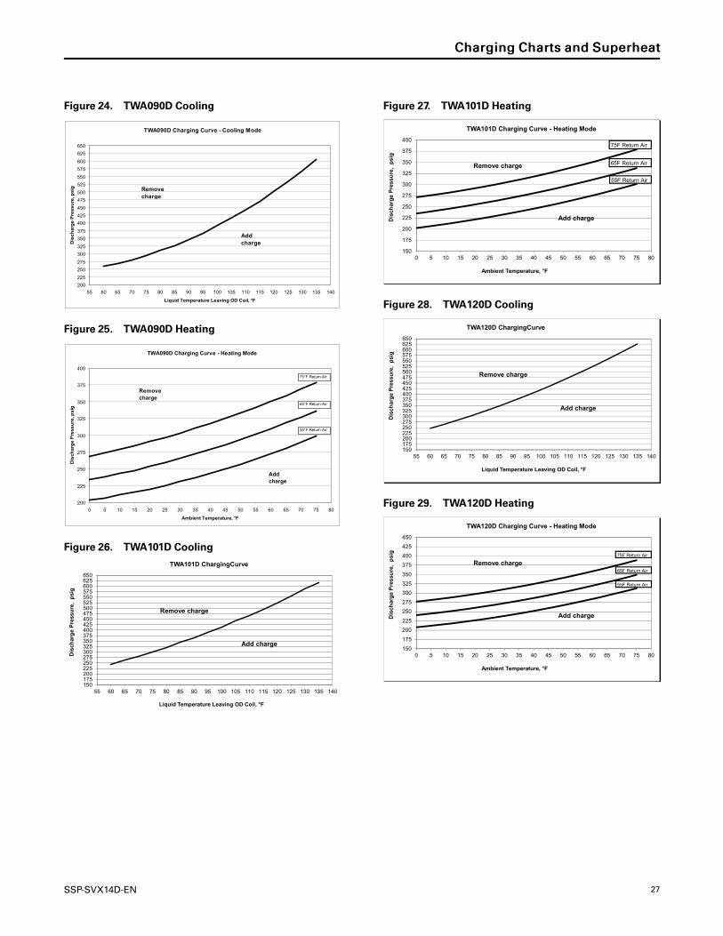
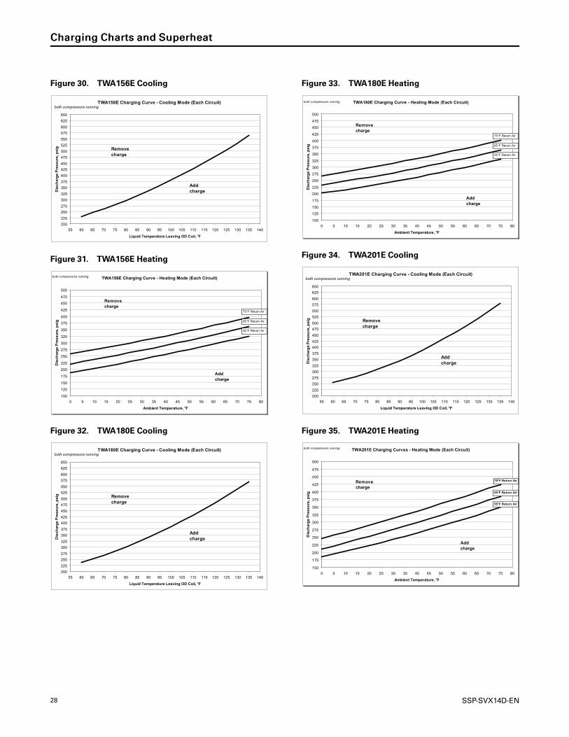
Charging Charts and Superheat
Figure 18. TWA061D Cooling
TWA061D Charging Curve - Cooling Mode
200
225
250
275
300
325
350
375
400
425
450
475
500
525
550
575
600
625
650
55 60 65 70 75 80 85 90 95 100 105 110 115 120 125 130 135 140
Liquid Temperature Leaving OD Coil, °F
Dis
ch
arg
e P
res
su
re, p
sig
Add charge
Remove charge
Figure 19. TWA061D Heating
TWA061D Charging Curve - Heating Mode
150
175
200
225
250
275
300
325
350
375
400
425
450
0 5 10 15 20 25 30 35 40 45 50 55 60 65 70 75 80
Ambient Temperature, °F
Dis
ch
arg
e P
res
su
re, p
sig
Add charge
Remove charge
75°F Return Air
65°F Return Air
55°F Return Air
Figure 20. TWA073D Cooling
TWA073D Charging Curve - Cooling Mode
200
225
250
275
300
325
350
375
400
425
450
475
500
525
550
575
600
625
650
55 60 65 70 75 80 85 90 95 100 105 110 115 120 125 130 135 140
Liquid Temperature Leaving OD Coil, °F
Dis
ch
arg
e P
res
su
re, p
sig
Add charge
Remove charge
Figure 21. TWA073D Heating
TWA073D Charging Curve - Heating Mode
150
175
200
225
250
275
300
325
350
375
400
425
450
0 5 10 15 20 25 30 35 40 45 50 55 60 65 70 75 80
Ambient Temperature, °F
Dis
ch
arg
e P
res
su
re, p
sig
Add charge
Remove charge
75°F Return Air
65°F Return Air
55°F Return Air
Figure 22. TWA076D Cooling
TWA076D Charging Curve - Cooling Mode
200
225
250
275
300
325
350
375
400
425
450
475
500
525
550
575
600
625
650
55 60 65 70 75 80 85 90 95 100 105 110 115 120 125 130 135 140
Liquid Temperature Leaving OD Coil, °F
Dis
ch
arg
e P
res
su
re, p
sig
Add charge
Remove charge
Figure 23. TWA076D Heating
TWA076D Charging Curve - Heating Mode
175
200
225
250
275
300
325
350
375
400
0 5 10 15 20 25 30 35 40 45 50 55 60 65 70 75 80
Ambient Temperature, °F
Dis
ch
arg
e P
res
su
re, p
sig
Add charge
Remove charge
55°F Return Air
65°F Return Air
75°F Return Air
SSP-SVX14D-EN 27
Figure 24. TWA090D Cooling
TWA090D Charging Curve - Cooling Mode
200
225
250
275
300
325
350
375
400
425
450
475
500
525
550
575
600
625
650
55 60 65 70 75 80 85 90 95 100 105 110 115 120 125 130 135 140
Liquid Temperature Leaving OD Coil, °F
Dis
ch
arg
e P
res
su
re, p
sig
Add charge
Remove charge
Figure 25. TWA090D Heating
TWA090D Charging Curve - Heating Mode
200
225
250
275
300
325
350
375
400
0 5 10 15 20 25 30 35 40 45 50 55 60 65 70 75 80
Ambient Temperature, °F
Dis
ch
arg
e P
res
su
re, p
sig
Add charge
Remove charge
55°F Return Air
65°F Return Air
75°F Return Air
Figure 26. TWA101D Cooling
150175200225250275300325350375400425450475500525550575600625650
55 60 65 70 75 80 85 90 95 100 105 110 115 120 125 130 135 140
Dis
char
ge
Pre
ssu
re,
psi
g
Liquid Temperature Leaving OD Coil, °F
TWA101D ChargingCurve
Add charge
Remove charge
Figure 27. TWA101D Heating
150
175
200
225
250
275
300
325
350
375
400
0 5 10 15 20 25 30 35 40 45 50 55 60 65 70 75 80
Dis
char
ge
Pre
ssu
re,
psi
g
Ambient Temperature, °F
TWA101D Charging Curve - Heating Mode
Add charge
Remove charge
75F Return Air
65F Return Air
55F Return Air
Figure 28. TWA120D Cooling
150175200225250275300325350375400425450475500525550575600625650
55 60 65 70 75 80 85 90 95 100 105 110 115 120 125 130 135 140
Dis
char
ge
Pre
ssu
re,
psi
g
Liquid Temperature Leaving OD Coil, °F
TWA120D ChargingCurve
Add charge
Remove charge
Figure 29. TWA120D Heating
150
175
200
225
250
275
300
325
350
375
400
425
450
0 5 10 15 20 25 30 35 40 45 50 55 60 65 70 75 80
Dis
char
ge
Pre
ssu
re,
psi
g
Ambient Temperature, °F
TWA120D Charging Curve - Heating Mode
Add charge
Remove charge75F Return Air
55F Return Air
65F Return Air
CChhaarrggiinngg CChhaarrttss aanndd SSuuppeerrhheeaatt
28 SSP-SVX14D-EN
Figure 30. TWA156E Cooling
TWA156E Charging Curve - Cooling Mode (Each Circuit)
200
225
250
275
300
325
350
375
400
425
450
475
500
525
550
575
600
625
650
55 60 65 70 75 80 85 90 95 100 105 110 115 120 125 130 135 140
Liquid Temperature Leaving OD Coil, °F
Dis
ch
arg
e P
res
su
re, p
sig
Add charge
Remove charge
both compressors running
Figure 31. TWA156E Heating
TWA156E Charging Curve - Heating Mode (Each Circuit)
100
125
150
175
200
225
250
275
300
325
350
375
400
425
450
475
500
0 5 10 15 20 25 30 35 40 45 50 55 60 65 70 75 80
Ambient Temperature, °F
Dis
ch
arg
e P
res
su
re, p
sig
Add charge
Remove charge
55°F Return Air
65°F Return Air
75°F Return Air
both compressors running
Figure 32. TWA180E Cooling
TWA180E Charging Curve - Cooling Mode (Each Circuit)
200
225
250
275
300
325
350
375
400
425
450
475
500
525
550
575
600
625
650
55 60 65 70 75 80 85 90 95 100 105 110 115 120 125 130 135 140
Liquid Temperature Leaving OD Coil, °F
Dis
ch
arg
e P
res
su
re, p
sig
Add charge
Remove charge
both compressors running
Figure 33. TWA180E Heating
TWA180E Charging Curve - Heating Mode (Each Circuit)
100
125
150
175
200
225
250
275
300
325
350
375
400
425
450
475
500
0 5 10 15 20 25 30 35 40 45 50 55 60 65 70 75 80
Ambient Temperature, °F
Dis
ch
arg
e P
res
su
re, p
sig
Add charge
Remove charge
55°F Return Air
65°F Return Air
75°F Return Air
both compressors running
Figure 34. TWA201E Cooling
TWA201E Charging Curve - Cooling Mode (Each Circuit)
200
225
250
275
300
325
350
375
400
425
450
475
500
525
550
575
600
625
650
55 60 65 70 75 80 85 90 95 100 105 110 115 120 125 130 135 140
Liquid Temperature Leaving OD Coil, °F
Dis
ch
arg
e P
res
su
re, p
sig
Add charge
Remove charge
both compressors running
Figure 35. TWA201E Heating
TWA201E Charging Curves - Heating Mode (Each Circuit)
150
175
200
225
250
275
300
325
350
375
400
425
450
475
500
0 5 10 15 20 25 30 35 40 45 50 55 60 65 70 75 80
Ambient Temperature, °F
Dis
ch
arg
e P
res
su
re, p
sig
Add charge
Remove charge
55°F Return Air
65°F Return Air
both compressors running
75°F Return Air
CChhaarrggiinngg CChhaarrttss aanndd SSuuppeerrhheeaatt

SSP-SVX14D-EN 29
Figure 36. TWA240E Cooling
TWA240E Charging Curve - Cooling Mode (Each Circuit)
200
225
250
275
300
325
350
375
400
425
450
475
500
525
550
575
600
625
650
55 60 65 70 75 80 85 90 95 100 105 110 115 120 125 130 135 140
Liquid Temperature Leaving OD Coil, °F
Dis
ch
arg
e P
res
su
re, p
sig
Add charge
Remove charge
both compressors running
Figure 37. TWA240E Heating
TWA240E Charging Curves - Heating Mode (Each Circuit)
150
175
200
225
250
275
300
325
350
375
400
425
450
475
500
0 5 10 15 20 25 30 35 40 45 50 55 60 65 70 75 80
Ambient Temperature, °F
Dis
ch
arg
e P
res
su
re, p
sig
Add charge
Remove charge
55°F Return Air
65°F Return Air
both compressors running
75°F Return Air
Table 9. TWA superheat with matched TWE air handler
Condenser Air Handler
Cooling Superheat Heating Superheat
Circuit 1 Circuit 2 Circuit 1 Circuit 2
TWA061D TWE076D 14.9 — 12.7 —
TWA073D TWE090D 14.9 — 12.7 —
TWA076D TWE076D 16.0 — 15.7 —
TWA090D TWE090D 16.0 — 15.7 —
TWA101D TWE101D 10.1 — 9.4 —
TWA120D TWE120D 10.1 — 9.4 —
TWA156E TWE156E 15.5 15.5 12.2 12.2
TWA180E TWE180E 15.5 15.5 12.2 12.2
TWA201E TWE201E 14.7 14.7 11.4 11.4
TWA240E TWE240E 14.7 14.7 11.4 11.4
Notes:1. An adjustable TXV is provided for each circuit in the TWE and TWAmodels. If the application causes the superheat to deviate from the values shown
above by more than 1 degree - after the system has achieved steady state - the TXV should be adjusted to provide the values shown as measured atthe compressor.
2. The values given above have been tested and are approved for the matched sets shown. If an alternate combination is used, an expansion deviceshould be used that provides 16-20°F degrees of superheat measured at the compressor.
3. Check and adjust superheat using this table, then compare with charging chart to determine if charge corrections are necessary.
CChhaarrggiinngg CChhaarrttss aanndd SSuuppeerrhheeaatt

30 SSP-SVX14D-EN
Installation ChecklistComplete this checklist once the unit is installed to
verify that all recommended procedures have been
accomplished before starting the system. Do not
operate the system until all items covered by this
checklist are complete.
Inspect unit location for proper required service
clearances.
Inspect unit location for proper free air clearances.
Inspect unit location for secure, level mounting
position.
Refrigerant PipingProperly sized/constructed liquid and suction lines
connected to stubs at both the indoor and outdoor
units?
Insulated the entire suction line?
Insulated portions of liquid line exposed to
extremes in temperature?
Performed initial leak test?
Evacuated each refrigerant circuit to 500 microns?
Charged each circuit with proper amount of R-
410A?
Electrical WiringProvided unit power wiring (with disconnect) to
proper terminals in the unit control section?
Installed system indoor thermostat?
Installed system low voltage interconnecting wiring
to proper terminals of outdoor unit, indoor unit and
system thermostat?

SSP-SVX14D-EN 31
Pre-StartControl Circuit FeaturesNNoottee:: Not all of these features may be required for your
unit, check electrical schematic.
Discharge Temperature Limit (DTL)The control’s sensor is located on the discharge line.
This device will shut off the compressor and the
outdoor fan(s) if the discharge temperature exceeds the
DTL setting. Once the discharge temperature has
returned to normal, the compressor will cycle back on.
Evaporator Defrost Control (EDC)This control is located in the Air Handler. The control’s
sensing tube is embedded vertically in the evaporator
coil, near the center. This device will stop the
compressor if the indoor coil temperature drops below
its setting. The indoor air will still circulate across the
coil bringing the temperature of the coil back up to the
cut-in temperature of the evaporator defrost control.
Low Pressure Cut-Out (LPCO)This control’s sensor is located in the suction (gas) line,
near the compressor. This control will stop the
compressor and the outdoor fans if suction pressure
drops below the Low Pressure Cut-Out setting. Once
the suction pressure has returned to normal, the
compressor and outdoor fans will cycle back on.
High Pressure Cut-Out (HPCO)This control’s sensor is located in the discharge line.
This device will shut off the compressor and the
outdoor fan(s) if the discharge pressure exceeds the
High Pressure Cut-Out’s setting. Once the discharge
pressure has returned to normal, the compressor will
cycle back on.
WWAARRNNIINNGGPPrreevveenntt IInnjjuurryy!!DDuuee ttoo aaggeennccyy ssaaffeettyy rreeqquuiirreemmeennttss,, nnoo sscchhrraaddeerr
ccoorree iiss ttoo bbee iinnssttaalllleedd bbeenneeaatthh tthhee HHPPCCOO.. RReemmoovvaall
ooff tthhee HHPPCCOO wwiitthhoouutt eevvaaccuuaattiinngg tthhee ssyysstteemm cchhaarrggee
ccoouulldd ccaauussee iinnjjuurryy aanndd rreelleeaassee ooff rreeffrriiggeerraanntt..
Internal Overload Protector (IOL)This device is embedded in the compressor. It will shut
off the compressor if the discharge temperature of the
compressor exceeds its design trip temperature.
NNoottee:: The IOL will put the compressor back inoperation once the compressor motor heat hasdropped below the trip setting; however, a checkof the refrigerant and electrical systems shouldbe made to determine the cause and becorrected.

32 SSP-SVX14D-EN
Start-UpReliaTel™™ ControlsThe ReliaTel™ Control is a microelectronic control
feature, which provides operating functions that are
significantly different than conventional
Electromechanical units. The ReliaTel™ Refrigeration
Module (RTRM) uses proportional/integral control
algorithms to perform specific unit functions that
govern the unit operation in response to application
conditions.
The RTRM provides compressor anti-short cycle (ASC)
timing functions through minimum““OOffff”” and ““OOnn””
timing to increase reliability, performance and to
maximize unit efficiency. Upon power initialization, the
RTRM performs self-diagnostic checks to insure that all
internal controls are functioning. It also checks the
configuration parameters against the components
connected to the system. The system LED located on
the RTRMmodule is turned ““OOnn”” within one second
after power-up if all internal operations are correct.
The heating and cooling cycles of the heat pump are
automatic for Heat and Cool functions when using an
optional automatic changeover thermostat (TS).
The fan switch on the optional automatic changeover
thermostat can be placed in either the OONN position,
causing continuous evaporator (indoor) fan operation,
or the AAUUTTOO position causing fan operation to coincide
with heating or cooling run cycles. (In AAUUTTOO position,
the fan switch automatically changes to Heat or Cool in
response to sufficient room temperature change.)
TerminologyThe following terms and acronyms may be used in this
section.
ASC Anti-Short Cycle Timer
CC Compressor Contactor
CCH Crankcase Heater
CF Outdoor Fan Capacitor
CHR Crankcase Heater Relay
COMM Communication Interface Module
CPR Compressor
CTS Coil Temperature Sensor
DTL Discharge Temperature Limit Switch
EDC Evaporator Defrost Control Switch
FTB Outdoor Fan Terminal Block
HPC High Pressure Cutout Switch
HTB High Voltage Terminal Block
LPC Low Pressure Cutout Switch
LTB Low Voltage Terminal Board
OAS Outdoor Air Temperature Sensor
ODF Outdoor Fan Relay
ODM Outdoor Fan Motor
PM Phase Monitor
RTRM ReliaTel ™ Refrigeration Module
SOV Switchover Valve
TNS Transformer
Functions and FeaturesThese subsections describe the following key heat
pump functions and features:
• Processing Activated When the Disconnect Switch
is in OONN Position
• Mechanical Heat
• Auxiliary Heat
• Emergency Heat
• Cooling
• Demand Defrost
Processing Activated When the DisconnectSwitch is in the ON PositionThe following table lists the processing that occurs
given the stated condition.

SSP-SVX14D-EN 33
Condition Resulting Operations
If the disconnect switch is in theON position…
1. Current is supplied to the compressor crankcase heater(s) (CCH) through the normally closed contactsof the crankcase heater relay (CHR) when the compressor is not running.
2. The phase monitor (PM) is powered.
3. The phase monitor (PM) looks at the incoming power to verify that there is no reversed phase, nophase imbalance, and no loss of phase. If the phase monitor detects any of these three conditions, itwill shut off control voltage.
4. The control transformer (TNS) is powered.
5. The ReliaTel ™ control board (RTRM) is powered and performs self-diagnostic checks to insure that allinternal controls are functioning.
6. The ReliaTel ™ control board (RTRM) checks the configuration parameters against the componentsconnected to the system.
7. The system LED located on the RTRMmodule is turnedON within one second after power-up if allinternal operations are correct.
8. The communications board (COMM) is powered if installed.
9. The indoor thermostat (TS) is powered.
Mechanical HeatIn Heat mode the switchover valve (SOV) is turned OOFFFF.
When a request for heating occurs, the control system
turns OONN the mechanical heat (compressors) to
perform heating. Dual circuit heat pumps are factory
configured to have 2-step mechanical heating enabled
(RTRM J4-3 tied to ground).
The staging sequence depends on the type of
mechanical heating that is enabled.
• If 1-Step mechanical heating is enabled (RTRM J4-3
not tied to ground), the unit will stage according to
Table 12, p. 35, as a result of the proportional/
integral control algorithms.
• Units with 2-step mechanical heating will stage
according to Table 13, p. 35, as a result of the
proportional/integral control algorithms.
With mechanical heating, when a heat request is turned
OONN, the Indoor Fan request is turned OONN. When the
heat request is turned OOFFFF, the Indoor Fan request is
turned OOFFFF after a specified delay (60 seconds on all
dual-compressor units and 80 seconds on all single
compressor units). See Table 10, p. 34, Table 11, p. 35,
Table 12, p. 35, and Table 13, p. 35 in this document for
the staging, sequence, and control.
Auxiliary HeatAuxiliary Heat is factory disabled on all Odyssey units
(Jumper placed between J2-1 and J2-2 RTRM inputs). If
configured (Jumper wire cut or removed between J2-1
and J2-2 on RTRM) and installed, Auxiliary Heat is
enabled or disabled by Smart Recovery.
Smart RecoverySmart Recovery dictates that if the Active Zone
Temperature is making a recovery using only
mechanical heating toward the setpoint at a rate of at
least 6°F/hour (0.1°F/minute), the electric heat is
disabled. If Smart Recovery is not disabling electric
heat, an approximate 9 minute stage-up delay (plus or
minus a few minutes) is provided for each stage to
allow time for recovery to begin. Stages of electric heat
are enabled and energized as necessary to meet
heating demand. When the request for Auxiliary Heat is
removed, the Indoor Fan request is turned OOFFFF at the
same time as the Electric Heat Stages. See Table 10, p.
34, Table 11, p. 35, Table 12, p. 35, and Table 13, p. 35
for the staging, sequence, and control.
All split system units are also configured from the
factory for only 1-Stage of Electric Heat (Jumper placed
between J1-3 and J1-6 RTRM inputs). To enable two
stages of Electric Heat, cut or remove the jumper
between J1-3 and J1-6 RTRM inputs.
Emergency HeatWhen Emergency Heat mode is requested and
Auxiliary Electric Heat is configured and installed, only
the Auxiliary Electric Heat will be turned OONN to satisfy
the Heat request. Mechanical heat will be held OOFFFF.
When the request for Emergency Heat is initiated, the
Indoor Fan request is turned OONN 1 second before the
electric heat stages are activated. See Table 10, p. 34,
Table 11, p. 35, Table 12, p. 35, and Table 13, p. 35for
the staging, sequence, and control.
CoolingWith a request for Cooling, the RTRM stages the
circuits and control normally for single and dual stage
SSttaarrtt--UUpp

34 SSP-SVX14D-EN
cooling applications. If the unit is configured with a
zone sensor, switchover valve 1 (SOV1) and switchover
valve 2 (SOV2) are energized for the duration of the
Cooling mode and do not change states until the unit
either enters OOFFFF mode or transitions to Heat mode. If
the unit is controlled with a thermostat, SOV1 and
SOV2 are energized while the thermostat W1/O signal
output to the RTRM is active.
The outdoor fans (ODF) will turn OONN and OOFFFF with the
compressors. Circuit 1 fan cycles with compressor 1
and circuit 2 fan will cycle with compressor. If a
compressor is turned OOFFFF, the anti-short cycle timer
(ASC) will hold the compressor OOFFFF for 3 minutes. See
Table 10, p. 34, Table 11, p. 35, Table 12, p. 35, and
Table 13, p. 35 for the staging, sequence, and control.
Demand DefrostWhen power is first applied to the unit, the first
demand-defrost cycle will be initiated based on a
cumulative run time of exactly 30 minutes only at the
required conditions. The cumulative run time at the
required conditions is tracked separately for each
compressor.
Shortly after completion of the first defrost cycle, the
system control calculates the temperature difference
between the outdoor coil and outdoor air, using the
result as an indicator of unit performance at dry coil
conditions.
Conditions Triggering the Defrost CycleOver time, as moisture and frost accumulate on the
coil, the coil temperature will drop, increasing the
temperature difference. When the temperature
difference is large enough, a defrost cycle is initiated.
Demand Defrost is initiated when the outdoor air
temperature (OAS) is below 52°F and the outdoor coil
temperature (CTS) is below 33°F.
Single and Dual CircuitsWhen a circuit enters Defrost mode, the compressor
will remain energized, the associated outdoor fan
(ODF) will de-energize, the associated switchover valve
(SOV) output will energize, and the first stage of
Auxiliary Heat energizes.
On dual circuit units, the opposite circuit's state will
remain unchanged if a defrost cycle has not been
initiated on that circuit. Each circuit will enter defrost
independently based on its associated Outdoor Coil
Temperature Sensor (CTS), the Outdoor Air
Temperature Sensor (OAS), and its total accumulated
run time.
Termination of the Defrost CycleA circuit will leave defrost, during normal conditions,
once the outdoor coil temperature reaches the outdoor
air temperature + 47°F which must be above 57°F and
not greater than 72°F. Termination of the defrost cycle
includes a "Soft Start" delay of 5 seconds for the
switchover valve (SOV) where the outdoor fans (ODF)
are turned on 5 seconds before the switchover valve
(SOV) is returned to the heating position to help
smooth the transition.
Behavior of Switchover ValvesThe switchover valves (SOV) will both be energized
during cooling mode and will be de-energized during
Heat or OOFFFF mode. However, during a defrost cycle,
only the circuit that requires a defrost cycle will
energize its switchover valve (SOV). For thermostat
control, if a thermostat is requesting for the switchover
(SOV) to be energized or de-energized, both switchover
valve (SOV) outputs will follow the thermostat request
(unless a circuit is in a defrost cycle).
Defrost Configuration FactsUnits are configured from the factory to have
Independent Circuit defrost (RTRM input J9-3 tied to
ground with RTRM input J1-5 OPEN).
Table 10. Heat pump operation with thermostat
Inputs Outputs
Y1 Y2 G W1 W2 O X2 Cool Heat1 Indoor Fan
ON OFF Don'tCare
Don'tCare
OFF HEAT OFF OFF Stage 1 ON
OFF ON Don'tCare
Don'tCare
OFF HEAT OFF OFF Stage 2 ON
ON ON Don'tCare
Don'tCare
OFF HEAT OFF OFFStage 1 +Stage 2 ON
ON OFF Don'tCare
Don'tCare
ON HEAT OFF OFFStage 1 +Auxiliary ON
OFF ON Don'tCare
Don'tCare
ON HEAT OFF OFFStage 2 +Auxiliary ON
ON ON Don'tCare
Don'tCare
ON HEAT OFF OFFStage 1 +Stage 2 +Auxiliary
ON
SSttaarrtt--UUpp
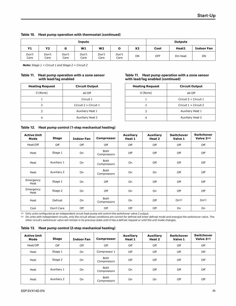
SSP-SVX14D-EN 35
Table 10. Heat pump operation with thermostat (continued)
Inputs Outputs
Y1 Y2 G W1 W2 O X2 Cool Heat1 Indoor Fan
Don'tCare
Don'tCare
Don'tCare
Don'tCare
Don'tCare
Don'tCare
ON OFF Em Heat ON
Note: Stage 1 = Circuit 1 and Stage 2 = Circuit 2
Table 11. Heat pump operation with a zone sensorwith lead/lag enabled
Heating Request Circuit Output
0 (None) All Off
1 Circuit 1
2 Circuit 2 + Circuit 1
3 Auxiliary Heat 1
4 Auxiliary Heat 2
Table 11. Heat pump operation with a zone sensorwith lead/lag enabled (continued)
Heating Request Circuit Output
0 (None) All Off
1 Circuit 2 + Circuit 1
2 Circuit 1 + Circuit 2
3 Auxiliary Heat 1
4 Auxiliary Heat 2
Table 12. Heat pump control (1-step mechanical heating)
Active UnitMode Stage Indoor Fan Compressor
AuxiliaryHeat 1
AuxiliaryHeat 2
SwitchoverValve 1
SwitchoverValve 2(a)
Heat/Off Off Off Off Off Off Off Off
Heat Stage 1 OnBoth
Compressors Off Off Off Off
Heat Auxiliary 1 OnBoth
Compressors On Off Off Off
Heat Auxiliary 2 OnBoth
Compressors On On Off Off
EmergencyHeat
Stage 1 On Off On Off Off Off
EmergencyHeat
Stage 2 On Off On On Off Off
Heat Defrost OnBoth
Compressors On Off On(b) On(b)
Cool Don’t Care Off Off Off Off On On
(a) Only units configured as an independent circuit heat pump will control the switchover valve 2 output.(b) On units with independent circuits, only the circuit whose conditions are correct for defrost will enter defrost mode and energize the switchover valve. The
other circuit's switchover valve will remain in its previous state until it has a defrost request or until the unit mode changes.
Table 13. Heat pump control (2-step mechanical heating)
Active UnitMode Stage Indoor Fan Compressor
AuxiliaryHeat 1
AuxiliaryHeat 2
SwitchoverValve 1
SwitchoverValve 2(a)
Heat/Off Off Off Off Off Off Off Off
Heat Stage 1 On Compressor 1 Off Off Off Off
Heat Stage 2 OnBoth
Compressors Off Off Off Off
Heat Auxiliary 1 OnBoth
Compressors On Off Off Off
Heat Auxiliary 2 OnBoth
Compressors On On Off Off
SSttaarrtt--UUpp

36 SSP-SVX14D-EN
Table 13. Heat pump control (2-step mechanical heating) (continued)
Active UnitMode Stage Indoor Fan Compressor
AuxiliaryHeat 1
AuxiliaryHeat 2
SwitchoverValve 1
SwitchoverValve 2(a)
EmergencyHeat
Stage 1 On Off On Off Off Off
EmergencyHeat
Stage 2 On Off On On Off Off
Heat Defrost OnBoth
Compressors On Off On(b) On(b)
Cool Don’t Care Off Off Off Off On On
(a) Only units configured as an independent circuit heat pump will control the switchover valve 2 output.(b) On units with independent circuits, only the circuit whose conditions are correct for defrost will enter defrost mode and energize the switchover valve. The
other circuit's switchover valve will remain in its previous state until it has a defrost request or until the unit mode changes.
SSttaarrtt--UUpp

SSP-SVX14D-EN 37
Service Test Modes for ReliaTel™™ ControlsTest ModesUpon power initialization, the RTRM performs self-
diagnostic checks to ensure that all internal controls are
functional. It also checks the configuration parameters
against the components connected to the system. The
system LED located on the RTRMmodule is turned
““OOnn”” within one second of power-up if internal
operation is okay.
Use one of the following ““TTeesstt”” procedures to bypass
some time delays and to start the unit at the control
panel. Each step of unit operation can be activated
individually by temporarily shorting across the ““TTeesstt””
terminals for 2 to 3 seconds. The system LED located
on the RTRMmodule will blink when the test mode has
been initiated. The unit can be left in any ““TTeesstt”” step
for up to one hour before it will automatically
terminate, or it can be terminated by opening the main
power disconnect switch. Once the test mode has been
terminated, the system LED will glow continuously and
the unit will revert to the ““SSyysstteemm”” control.
There are three methods in which the ““SSeerrvviiccee TTeesstt””
can be cycled at LTB-Test 1(T1) and LTB-Test 2 (T2).
Step Test ModeThis method initiates the different components of the
unit, one at a time, by temporarily shorting across the
two test terminals for 2 to 3 seconds.
For the initial start-up of the unit, this method allows
the technician to cycle a component ““OOnn”” and have up
to one hour to complete the check. Service Test Mode
will be ignored if a short is present across Test 1 and
Test 2 at start-up.
Resistance Test ModeThis method can be used for start-up when a decade
box for variable resistance outputs is available. This
method initiates the different components of the unit,
one at a time, when a specific resistance value is placed
across the two test terminals. The unit will remain in
the specific test mode for approximately one hour even
though the resistance is left on the test terminals.
Table 14. Test mode states for SZVAV independent circuit heat pump units with auxiliary electric heat
TEST STEP MODEFA-N VFD COMMAND COMP 1 COMP 2 HEAT 1 HEAT 2
SO-V1
SO-V2 OHMS
1 FAN ON ON 58% (0 - 2.8 VDC) OFF OFF OFF OFF OFF OFF 2.2K
2 COOL 1 ON 86% (3.8 - 7.7 VDC) ON OFF OFF OFF ON ON 4.7K
3 COOL 2 ON 100% (5.6 - 10 VDC) ON ON OFF OFF ON ON 6.8K
4 HEAT 1 ON 100% (5.6 - 10 VDC) ON OFF OFF OFF OFF OFF 10K
5 HEAT 2 ON 100% (5.6 - 10 VDC) ON ON OFF OFF OFF OFF 15K
6 Heat 3 ON 100% (5.6 - 10 VDC) ON ON ON OFF OFF OFF 22K
7 Heat 4 ON 100% (5.6 - 10 VDC) ON ON ON ON OFF OFF 27K
8 Defrost ON 100% (5.6 - 10 VDC) ON ON ON OFF ON ON 33K
9 Emergency Heat ON 100% (5.6 - 10 VDC) OFF OFF ON ON OFF OFF 47K
Auto Test ModeThis method is not recommended for start-up due to
the short timing between individual component steps.
This method initiates the different components of the
unit, one at a time, when a fixed jumper is installed
across the test terminals.
The unit will start the first test step and change to the
next step every 30 seconds. At the end of the test
mode, control of the unit will automatically revert to the
applied ““SSyysstteemm”” control method. For unit test steps,
test modes, and step resistance values to cycle the
various components, refer to Table 14, p. 37.

38 SSP-SVX14D-EN
TroubleshootingTroubleshooting ReliaTel™Controls
WWAARRNNIINNGGLLiivvee EElleeccttrriiccaall CCoommppoonneennttss!!FFaaiilluurree ttoo ffoollllooww aallll eelleeccttrriiccaall ssaaffeettyy pprreeccaauuttiioonnss
wwhheenn eexxppoosseedd ttoo lliivvee eelleeccttrriiccaall ccoommppoonneennttss ccoouulldd
rreessuulltt iinn ddeeaatthh oorr sseerriioouuss iinnjjuurryy..
WWhheenn iitt iiss nneecceessssaarryy ttoo wwoorrkk wwiitthh lliivvee eelleeccttrriiccaall
ccoommppoonneennttss,, hhaavvee aa qquuaalliiffiieedd lliicceennsseedd eelleeccttrriicciiaann
oorr ootthheerr iinnddiivviidduuaall wwhhoo hhaass bbeeeenn pprrooppeerrllyy ttrraaiinneedd
iinn hhaannddlliinngg lliivvee eelleeccttrriiccaall ccoommppoonneennttss ppeerrffoorrmm
tthheessee ttaasskkss..
The RTRM has the ability to provide the service
personnel with some unit diagnostics and system
status information.
Before turning the main power disconnect switch ““OOffff,,””
follow the steps below to check the ReliaTel™
Refrigeration Module (RTRM). All diagnostics & system
status information stored in the RTRM will be lost when
the main power is turned ““OOffff””.
To prevent injury or death from electrocution, it is the
responsibility of the technician to recognize this hazard
and use extreme care when performing service
procedures with the electrical power energized.
NNoottee:: The J6 & J7 screw terminals must be tightenedin order to accurately measure voltage in therequired steps.
1. Verify that the system LED on the RTRM is burning
continuously. If the LED is lit, go to Step 3.
2. If the LED is not lit, verify that 24 VAC is present
between J1-1 and J1-2. If 24 VAC is present,
proceed to Step 3. If 24 VAC is not present, check
the unit main power supply, check transformer
(TNS1). Proceed to Step 3 if necessary.
3. Utilizing “Method 1,” p. 38 or “Method 2,” p. 39 in
the System Status Checkout Procedure section,
check the following:
• System status
• Heating status
• Cooling status
NNoottee:: If a System failure is indicated, proceed toStep 4. If no failures are indicated, proceed toStep 5.
4. If a System failure is indicated, recheck Step 1 and
Step 2. If the LED is not lit in Step 1, and 24 VAC is
present in Step 2, then the RTRM has failed.
Replace the RTRM.
5. If no failures are indicated, use one of the TEST
mode procedures described in the “Service Test
Modes chapter,” p. 37 to start the unit. This
procedure will allow you to check all of the RTRM
outputs, and all of the external controls (relays,
contactors, etc.) that the RTRM outputs energize, for
each respective mode. Proceed to Step 6.
6. Step the system through all of the available modes,
and verify operation of all outputs, controls, and
modes. If a problem in operation is noted in any
mode, you may leave the system in that mode for
up to one hour while troubleshooting. Refer to the
sequence of operations for each mode, to assist in
verifying proper operation. Make the necessary
repairs and proceed to Step 7 and Step 8.
7. If no abnormal operating conditions appear in the
test mode, exit the test mode by turning the power
““OOffff”” at the main power disconnect switch.
8. Refer to the individual component test procedures if
other microelectronic components are suspect.
System Status CheckoutProcedure““SSyysstteemm SSttaattuuss”” is checked by using one of the
following two methods:
Method 1If the Zone Sensor Module (ZSM) is equipped with a
remote panel with LED status indication, you can check
the unit within the space. If the ZSM does not have
LED’s, use “Method 2,” p. 39. BAYSENS010B,
BAYSENS011B, BAYSENS119A, BAYSENS020A,
BAYSENS021A, BAYSENS023A, BAYSENS109 and
BAYSENS110 all have the remote panel indication
feature. The LED descriptions are listed below.
• LLEEDD 11 ((SSyysstteemm))
– ““OOnn”” during normal operation.
– ““OOffff”” if a system failure occurs or the LED fails.
– ““FFllaasshhiinngg”” indicates test mode
• LLEEDD 22 ((HHeeaatt))
– ““OOnn”” when the heat cycle is operating.
– ““OOffff”” when the heat cycle terminates or the LED
fails.
– ““FFllaasshhiinngg”” indicates a heating failure.
• LLEEDD 33 ((CCooooll))
– ““OOnn”” when the cooling cycle is operating.
– ““OOffff”” when the cooling cycle terminates or the
LED fails.
– ““FFllaasshhiinngg”” indicates a cooling failure.
The following information describes the complete
listing of failure indication causes.

SSP-SVX14D-EN 39
System FailureCheck the voltage between terminals 6 and 9 on J6, it
should read approximately 32 VDC. If no voltage is
present, a System failure has occurred. Refer to Step 4
in the previous section for the recommended
troubleshooting procedure.
Cooling Failure1. Cooling and heating set point (slide pot) on the
zone sensor has failed. Refer to the “Programmable
& Digital Zone Sensor Test,” p. 40.
2. Zone temperature thermistor ZTEMP on ZTS failed.
Refer to the “Programmable & Digital Zone Sensor
Test,” p. 40.
3. CC1 or CC2 24 VAC control circuit has opened,
check CC1 & CC2 coils, and any of the controls
below that apply to the unit (HPC1, HPC2, DTL1,
DTL2).
4. LPC1 has opened during the 3 minute minimum “on
time” during 4 consecutive compressor starts,
check LPC1 or LPC2 by testing voltage between the
J1-8 & J3-2 terminals on the RTRM and ground. If
24 VAC is present, the LPCs have not tripped. If no
voltage is present, LPCs have tripped.
Simultaneous Heat and Cool Failure
WWAARRNNIINNGGLLiivvee EElleeccttrriiccaall CCoommppoonneennttss!!FFaaiilluurree ttoo ffoollllooww aallll eelleeccttrriiccaall ssaaffeettyy pprreeccaauuttiioonnss
wwhheenn eexxppoosseedd ttoo lliivvee eelleeccttrriiccaall ccoommppoonneennttss ccoouulldd
rreessuulltt iinn ddeeaatthh oorr sseerriioouuss iinnjjuurryy..
WWhheenn iitt iiss nneecceessssaarryy ttoo wwoorrkk wwiitthh lliivvee eelleeccttrriiccaall
ccoommppoonneennttss,, hhaavvee aa qquuaalliiffiieedd lliicceennsseedd eelleeccttrriicciiaann
oorr ootthheerr iinnddiivviidduuaall wwhhoo hhaass bbeeeenn pprrooppeerrllyy ttrraaiinneedd
iinn hhaannddlliinngg lliivvee eelleeccttrriiccaall ccoommppoonneennttss ppeerrffoorrmm
tthheessee ttaasskkss..
• Emergency Stop is activated.
Method 2The second method for determining system status is
done by checking voltage readings at the RTRM (J6).
The system indication descriptions and the
approximate voltages are listed below.
System FailureMeasure the voltage between terminals J6-9 & J6-6.
• NNoorrmmaall OOppeerraattiioonn = approximately 32 VDC
• SSyysstteemm FFaaiilluurree = less than 1 VDC, approximately
0.75 VDC
• TTeesstt MMooddee = voltage alternates between 32 VDC &
0.75 VDC
Heat FailureMeasure the voltage between terminals J6-7 & J6-6.
• HHeeaatt OOppeerraattiinngg = approximately 32 VDC
• HHeeaatt OOffff = less than 1 VDC, approximately 0.75 VDC
• HHeeaattiinngg FFaaiilluurree = voltage alternates between 32
VDC & 0.75 VDC
Cool FailureMeasure the voltage between terminals J6-8 & J6-6.
• CCooooll OOppeerraattiinngg = approximately 32 VDC
• CCooooll OOffff = less than 1 VDC, approximately 0.75 VDC
• CCoooolliinngg FFaaiilluurree = voltage alternates between 32
VDC & 0.75 VDC
To use LED’s for quick status information at the unit,
purchase a BAYSENS010B ZSM and connect wires with
alligator clamps to terminals 6 through 10. Connected
each respective terminal wire (6 through 10) from the
Zone Sensor to the unit J6 terminals 6 through 10.
NNoottee:: If the system is equipped with a programmablezone sensor, (BAYSENS119A, or BAYSENS023A),the LED indicators will not function while theBAYSENS010A is connected.
Temperature TestsNNoottee:: These procedures are not for programmable or
digital models and are conducted with the ZoneSensor Module electrically removed from thesystem.
Test 1 - Zone Temperature Thermistor(ZTEMP)This component can be tested by measuring the
resistance between terminals 1 and 2 on the Zone
Temperature Sensor. See Table 15, p. 39 for typical
indoor temperatures, and corresponding resistive
values.
Table 15. Typical indoor temperatures and values
Zone Temperature Nominal Resistance
50°F or 10.0°C 19.9 Kohms
55°F or 12.8°C 17.47 Kohms
60°F or 15.6°C 15.3 Kohms
65°F or 18.3°C 13.49 Kohms
70°F or 21.1°C 11.9 Kohms
75°F or 23.9°C 10.50 Kohms
80°F or 26.7°C 9.3 Kohms
85°F or 29.4°C 8.25 Kohms
90°F or 32.2°C 7.3 Kohms
Test 2 - Cooling Set Point (CSP) andHeating Set Point (HSP)CCooooll SSPP = Terminals 2 and 3
TTrroouubblleesshhoooottiinngg
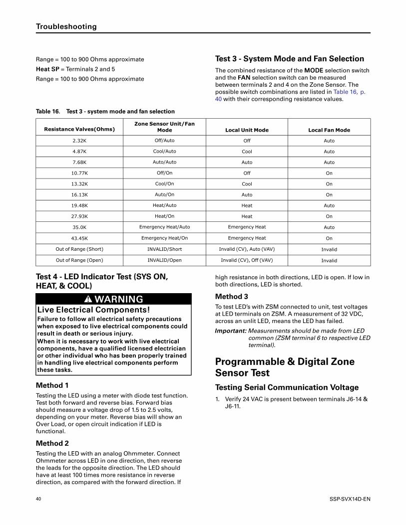
40 SSP-SVX14D-EN
Range = 100 to 900 Ohms approximate
HHeeaatt SSPP = Terminals 2 and 5
Range = 100 to 900 Ohms approximate
Test 3 - SystemMode and Fan SelectionThe combined resistance of the MMOODDEE selection switch
and the FFAANN selection switch can be measured
between terminals 2 and 4 on the Zone Sensor. The
possible switch combinations are listed in Table 16, p.
40 with their corresponding resistance values.
Table 16. Test 3 - systemmode and fan selection
Resistance Valves(Ohms)Zone Sensor Unit/Fan
Mode Local Unit Mode Local Fan Mode
2.32K Off/Auto Off Auto
4.87K Cool/Auto Cool Auto
7.68K Auto/Auto Auto Auto
10.77K Off/On Off On
13.32K Cool/On Cool On
16.13K Auto/On Auto On
19.48K Heat/Auto Heat Auto
27.93K Heat/On Heat On
35.0K Emergency Heat/Auto Emergency Heat Auto
43.45K Emergency Heat/On Emergency Heat On
Out of Range (Short) INVALID/Short Invalid (CV), Auto (VAV) Invalid
Out of Range (Open) INVALID/Open Invalid (CV), Off (VAV) Invalid
Test 4 - LED Indicator Test (SYS ON,HEAT, & COOL)
WWAARRNNIINNGGLLiivvee EElleeccttrriiccaall CCoommppoonneennttss!!FFaaiilluurree ttoo ffoollllooww aallll eelleeccttrriiccaall ssaaffeettyy pprreeccaauuttiioonnss
wwhheenn eexxppoosseedd ttoo lliivvee eelleeccttrriiccaall ccoommppoonneennttss ccoouulldd
rreessuulltt iinn ddeeaatthh oorr sseerriioouuss iinnjjuurryy..
WWhheenn iitt iiss nneecceessssaarryy ttoo wwoorrkk wwiitthh lliivvee eelleeccttrriiccaall
ccoommppoonneennttss,, hhaavvee aa qquuaalliiffiieedd lliicceennsseedd eelleeccttrriicciiaann
oorr ootthheerr iinnddiivviidduuaall wwhhoo hhaass bbeeeenn pprrooppeerrllyy ttrraaiinneedd
iinn hhaannddlliinngg lliivvee eelleeccttrriiccaall ccoommppoonneennttss ppeerrffoorrmm
tthheessee ttaasskkss..
Method 1Testing the LED using a meter with diode test function.
Test both forward and reverse bias. Forward bias
should measure a voltage drop of 1.5 to 2.5 volts,
depending on your meter. Reverse bias will show an
Over Load, or open circuit indication if LED is
functional.
Method 2Testing the LED with an analog Ohmmeter. Connect
Ohmmeter across LED in one direction, then reverse
the leads for the opposite direction. The LED should
have at least 100 times more resistance in reverse
direction, as compared with the forward direction. If
high resistance in both directions, LED is open. If low in
both directions, LED is shorted.
Method 3To test LED’s with ZSM connected to unit, test voltages
at LED terminals on ZSM. A measurement of 32 VDC,
across an unlit LED, means the LED has failed.
IImmppoorrttaanntt:: Measurements should be made from LEDcommon (ZSM terminal 6 to respective LEDterminal).
Programmable & Digital ZoneSensor TestTesting Serial Communication Voltage1. Verify 24 VAC is present between terminals J6-14 &
J6-11.
TTrroouubblleesshhoooottiinngg

SSP-SVX14D-EN 41
WWAARRNNIINNGGLLiivvee EElleeccttrriiccaall CCoommppoonneennttss!!FFaaiilluurree ttoo ffoollllooww aallll eelleeccttrriiccaall ssaaffeettyy pprreeccaauuttiioonnss
wwhheenn eexxppoosseedd ttoo lliivvee eelleeccttrriiccaall ccoommppoonneennttss ccoouulldd
rreessuulltt iinn ddeeaatthh oorr sseerriioouuss iinnjjuurryy..
WWhheenn iitt iiss nneecceessssaarryy ttoo wwoorrkk wwiitthh lliivvee eelleeccttrriiccaall
ccoommppoonneennttss,, hhaavvee aa qquuaalliiffiieedd lliicceennsseedd eelleeccttrriicciiaann
oorr ootthheerr iinnddiivviidduuaall wwhhoo hhaass bbeeeenn pprrooppeerrllyy ttrraaiinneedd
iinn hhaannddlliinngg lliivvee eelleeccttrriiccaall ccoommppoonneennttss ppeerrffoorrmm
tthheessee ttaasskkss..
2. Disconnect wires from J6-11 and J6-12. Measure
the voltage between J6-11 and J6-12, should be
about 32 VDC.
3. Reconnect wires to terminals J6-11 and J6-12.
Measure voltage again between J6-11 and J6-12,
voltage should flash high and low every 0.5
seconds. The voltage on the low end will measure
about 19 VDC, while the voltage on the high end
will measure from approximately 24 to 38 VDC.
4. Verify all modes of operation, by running the unit
through all of the steps in “Service Test Modes for
ReliaTel Controls,” p. 37.
5. After verifying proper unit operation, exit the test
mode. Turn the fan on continuously at the ZSM, by
pressing the button with the fan symbol. If the fan
comes on and runs continuously, the ZSM is good.
If you are not able to turn the fan on, the ZSM is
defective.
RLCI Loss of CommunicationsIf the RLCI loses input from the building management
system, the RTRM will control in the default mode after
approximately 15 minutes. If the RTRM loses the
Heating and Cooling setpoint input, the RTRM will
control in the default mode instantaneously. The
temperature sensing thermistor in the Zone Sensor
Module is the only component required for the
““DDeeffaauulltt MMooddee”” to operate.
Resetting Cooling and HeatingLockoutsCooling Failures and Heating Lockouts are reset in an
identical manner.“Method 1,” p. 41 explains resetting
the system from the space; “Method 2,” p. 41 explains
resetting the system at the unit.
NNoottee:: Before resetting Cooling Failures and HeatingLockouts check the Failure Status Diagnostics bythe methods previously explained. Diagnosticswill be lost when the power to the unit isdisconnected.
Method 1To reset the system from the space, turn the MMOODDEE
selection switch at the zone sensor to the OOFFFF position.
After approximately 30 seconds, turn the MMOODDEE
selection switch to the desired mode, i.e. HHEEAATT, CCOOOOLL,
or AAUUTTOO.
Method 2To reset the system at the unit, cycle the unit power by
turning the disconnect switch OOFFFF and then OONN
Lockouts can be cleared through the building
management system. Refer to the building
management system instructions for more
information.
Zone Temperature Sensor (ZTS)Service IndicatorThe ZSM SERVICE LED is a generic indicator that will
signal the closing of a Normally Open switch at any
time, providing the Indoor Motor (IDM) is operating.
This indicator is usually used to indicate an airside fan
failure.
The RTRM will ignore the closing of this Normally
Open switch for 2 (±1) minutes. This helps prevent
nuisance SERVICE LED indications.
TTrroouubblleesshhoooottiinngg

42 SSP-SVX14D-EN
MaintenanceWWAARRNNIINNGG
HHaazzaarrddoouuss VVoollttaaggee ww//CCaappaacciittoorrss!!FFaaiilluurree ttoo ddiissccoonnnneecctt ppoowweerr aanndd ddiisscchhaarrggee
ccaappaacciittoorrss bbeeffoorree sseerrvviicciinngg ccoouulldd rreessuulltt iinn ddeeaatthh oorr
sseerriioouuss iinnjjuurryy..
DDiissccoonnnneecctt aallll eelleeccttrriicc ppoowweerr,, iinncclluuddiinngg rreemmoottee
ddiissccoonnnneeccttss aanndd ddiisscchhaarrggee aallll mmoottoorr ssttaarrtt//rruunn
ccaappaacciittoorrss bbeeffoorree sseerrvviicciinngg.. FFoollllooww pprrooppeerr lloocckkoouutt//
ttaaggoouutt pprroocceedduurreess ttoo eennssuurree tthhee ppoowweerr ccaannnnoott bbee
iinnaaddvveerrtteennttllyy eenneerrggiizzeedd.. FFoorr vvaarriiaabbllee ffrreeqquueennccyy
ddrriivveess oorr ootthheerr eenneerrggyy ssttoorriinngg ccoommppoonneennttss
pprroovviiddeedd bbyy TTrraannee oorr ootthheerrss,, rreeffeerr ttoo tthhee
aapppprroopprriiaattee mmaannuuffaaccttuurreerr’’ss lliitteerraattuurree ffoorr
aalllloowwaabbllee wwaaiittiinngg ppeerriiooddss ffoorr ddiisscchhaarrggee ooff
ccaappaacciittoorrss.. VVeerriiffyy wwiitthh aann aapppprroopprriiaattee vvoollttmmeetteerr
tthhaatt aallll ccaappaacciittoorrss hhaavvee ddiisscchhaarrggeedd..
FFoorr aaddddiittiioonnaall iinnffoorrmmaattiioonn rreeggaarrddiinngg tthhee ssaaffeeddiisscchhaarrggee ooff ccaappaacciittoorrss,, sseeee PPRROODD--SSVVBB0066AA--EENN..
NNOOTTIICCEEOOppeerraattiinngg UUnnddeerr VVaaccuuuumm!!FFaaiilluurree ttoo ffoollllooww tthheessee iinnssttrruuccttiioonnss wwiillll rreessuulltt iinn
ccoommpprreessssoorr ffaaiilluurree..
DDoo nnoott ooppeerraattee oorr aappppllyy ppoowweerr ttoo tthhee ccoommpprreessssoorr
wwhhiillee uunnddeerr aa vvaaccuuuumm..
Perform all of the indicated maintenance procedures at
the intervals scheduled. This will prolong the life of the
unit and reduce the possibility of costly equipment
failure.
MonthlyConduct the following maintenance inspections once
per month.
Check unit wiring to ensure all connections are tight
and that the wiring insulation is intact.
Inspect the condenser coils for dirt and debris. If the
coils appear dirty, clean them.
With the unit operating in the cooling mode, check
the suction and discharge pressures and compare
them with Pressure Curve values in unit Service
Facts. Record these readings on the “Maintenance
Log,” p. 44.
Annually (Cooling Season)The following maintenance procedures must be
performed at the beginning of each cooling season to
ensure efficient unit operation.
Perform all of the monthly maintenance
inspections.
With the unit operating, check unit superheat and
record the reading in the “Maintenance Log,” p. 44.
Remove any accumulation of dust and/or dirt from
the unit casing.
Remove corrosion from any surface and repaint.
Check the gasket around the control panel door to
ensure it fits correctly and is in good condition to
prevent water leakage.
Inspect the control panel wiring to ensure that all
connections are tight and that the insulation is
intact.
NNoottee:: Condenser fan motors are permanentlylubricated.
Check refrigerant piping and fittings for leaks
Inspect the condenser coils for dirt and debris. If the
coils appear dirty, clean them.
Coil CleaningRegular coil maintenance, including annual cleaning-
enhances the unit's operating efficiency by minimizing:
• compressor head pressure and amperage draw
• water carryover
• fan brake horsepower
• static pressure losses
At least once each year — or more often if the unit is
located in a “dirty” environment — clean the coil using
the instructions outlined below. Be sure to follow these
instructions as closely as possible to avoid damaging
the coils.
Tube and FinNNoottee:: To clean refrigerant coils, use a soft brush and a
sprayer. Contact your local Parts Center forappropriate detergents.
1. Remove enough panels from the unit to gain safe
access to coil.
2. Straighten any bent coil fins with a fin comb.
3. Remove loose dirt and debris from both sides of the
coil with a soft brush.
4. Mix the detergent with water according to the
manufacturer's instructions. If desired, heat the
solution to 150° F maximum to improve its
cleansing capability.
5. Pour the cleaning solution into the sprayer.
6. Spray the leaving-airflow side of the coil first; then
spray the opposite side of the coil. Allow the
cleaning solution to stand on the coil for five
minutes.
7. Rinse both sides of the coil with cool, clean water.
8. Inspect both sides of the coil; if it still appears to be
dirty, repeat Step 7 and 8.
9. Reinstall all of the components and panels removed

SSP-SVX14D-EN 43
in Step 1; then restore power to the unit.
10. Using a fin comb, straighten any coil fins that were
inadvertently bent during the cleaning process.
MMaaiinntteennaannccee

44 SSP-SVX14D-EN
Maintenance LogDate
Ambient
Temp.
(°F)
EvaporatorEnteringAir
Compressor
Superheat(°F)
(atcompressor)
Subcooling(°F)
(atservicevalve)
Dry
Bulb
Wet
Bulb
SuctionPressure
DischargePressure
Circuit#1
Circuit#2
Circuit#1
Circuit#2
(C1)
(C2)
(C1)
(C2)
Note:Perform
eachinspectiononcepermonth(duringcoolingseason)whileunitisoperating
MMaaiinntteennaannccee

SSP-SVX14D-EN 45
Wiring DiagramMatrix
Table 17. Wiring schematics R-410A heat pump
ModelNumber
TonRefrigerantCircuit
Voltage Hz PhSchematics
ConnectionDiagrams
ReliaTel ReliaTel
TWA061DD 5 Single 380-415 50 3 23130406 23130419
TWA073D3 6 Single 208-230 60 3 23130406 23130419
TWA073D4 6 Single 460 60 3 23130406 23130419
TWA073DW 6 Single 575 60 3 23130406 23130419
TWA073DK 6 Single 380 60 3 23130406 23130419
TWA076DD 6.25 Single 380-415 50 3 23130406 23130419
TWA090D3 7.5 Single 208-230 60 3 23130406 23130419
TWA090D4 7.5 Single 460 60 3 23130406 23130419
TWA090DW 7.5 Single 575 60 3 23130406 23130419
TWA090DK 7.5 Single 380 60 3 23130406 23130419
TWA101DD 8.33 Single 380-415 50 3 23130406 23130419
TWA120D3 10 Single 208-230 60 3 12131689 23130420DRW
TWA120D4 10 Single 460 60 3 23130406 23130419
TWA120DW 10 Single 575 60 3 23130406 23130419
TWA120DK 10 Single 380 60 3 23130406 23130419
TWA156ED 13 Dual 380-415 50 3 23130406 23130429
TWA180E3 15 Dual 208-230 60 3 23130406 23130429
TWA180E4 15 Dual 460 60 3 23130406 23130429
TWA180EW 15 Dual 575 60 3 23130406 23130429
TWA180EK 15 Dual 380 60 3 23130406 23130429
TWA201ED 16.7 Dual 380-415 50 3 23130406 23130429
TWA240E3 20 Dual 208-230 60 3 12131689 12131702
TWA240E4 20 Dual 460 60 3 23130406 23130429
TWA240EW 20 Dual 575 60 3 23130406 23130429
TWA240EK 20 Dual 380 60 3 23130406 23130429

46 SSP-SVX14D-EN
NNootteess
SSP-SVX14D-EN 47
NNootteess

NNootteess
The manufacturer optimizes the performance of homes and buildings around the world. A business of Ingersoll Rand,
the leader in creating and sustaining safe, comfortable and energy efficient environments, the manufacturer offers a
broad portfolio of advanced controls and HVAC systems, comprehensive building services, and parts. For more
information, visit www.IRCO.com.
The manufacturer has a policy of continuous product and product data improvements and reserves the right to change design and specifications without notice.
©2015 Trane All rights reserved
SSP-SVX14D-EN 14 Aug 2015
Supersedes SSP-SVX14C-EN (January 2014)
We are committed to using environmentally
conscious print practices that reduce waste.


