Eagle Window & Door Manufacturing Inc. is a wholly owned subsidiary of Andersen Corporation. “Andersen”, “Eagle” and all other marks where denoted are trademarks of Andersen Corporation and its subsidiary. © 2014 Andersen Corporation. All rights reserved. 9054076 BC Revised 12/23/14
Instructions are for typical, new wood-framed wall construction with weather protection in place. Instructions may not be right for all installations due to building design, construction materials or methods used and/or building or site conditions. Consult a contractor or architect for recommendations.Flanges on the unit alone will not properly flash and seal the window. Follow these instructions carefully.For questions call 1-888-888-7020. Due to ongoing product changes, updated test results and/or industry best practices, this installation procedure may change over time. For updated installation guides, removal instructions and/or additional installation information, visit eaglewindow.com.Contact local authorities or waste management companies for proper recycling and/or disposal of removed window or patio door.Please leave this guide with building owner.
Thank you for choosing Andersen.
Installation Guidefor E-Series/Eagle® High-Performance Mullion Windows with LVL Reinforcement and Installed Using Type B Clips
Use caution when working at elevated heights and around unit openings. Follow manufacturers’ instructions for ladders and/or scaffolding. Failure to do so may result in injury or death.
Windows and doors can be heavy. Use safe lifting techniques and a reasonable number of people with enough strength to lift, carry and install window and door products to avoid injury and/or product damage.
Follow manufacturers’ instructions for hand or power tools. Always wear safety glasses. Failure to do so may result in injury and/or product damage.
▶ Read guide from beginning to end before starting installation. Read all warnings and cautions during unit installation.
Tools Needed ∙ Safety Glasses ∙ Tape Measure ∙ Level ∙ Square ∙ Hammer ∙ Stapler ∙ Utility Knife or Scissors ∙ Nylon Block ∙ Rubber Mallet ∙ Power Drill and Bits ∙ Wood Clamps ∙ Nail Set
Do not carry or lift unit by extension jambs. Doing so may result in injury, product or property damage.
*Instruction guide viewable and downloadable at eaglewindow.com
The installation instructions included as part of these mullion instructions are not representative of a specific window type. Specific product installation instructions must be strictly followed to ensure proper installation. These mulling instructions apply to clad products only. All assemblies must be installed using a 1/2" R.O. For instructions using other mullion materials and/or clips, see the “Installation” section at eaglewindow.com.
▶ Check with your local building code official to identify and confirm compliance with local building code requirements.
Supplies Needed ∙ Shims or Spacers Made of Cedar or Other Impervious Material ∙ 2" Galvanized Roof Nails ∙ Screws of Various Sizes, as Required by Installation ∙ Backer Rod ∙ Flashing ∙ Sealant ∙ Low Expanding Foam ∙ Interior Trim and/or Jamb Extensions ∙ Mullion End Cap ∙ Type B Clips ∙ LVL Material for Mullion Reinforcement
Buildings constructed prior to 1978 may contain lead paint which could be disturbed during window replacement. For more information on proper management of lead paint, visit www.epa.gov/lead.

29054076
• Verify that the rough opening is plumb, level, square and sized appropriately.
1. Prepare Rough Opening
• Cut weather-resistant barrier in numbered order as shown.
2. Cut Weather-resistant Barrier
• Fold sides and bottom flaps of the weather-resistant barrier into the opening and staple to inside wall. Fold top flap up and temporarily fasten with tape as shown.
3. Secure Weather-resistant Barrier
Make a 6" cut up from each top corner at a 45° angle to allow the weather barrier to be lapped over the installation flange at the head of the window.
Level
SquarePlumb
Cut at 45°
Rough Opening
Tape up to Install Head Flashing
1
23
45
Weather-resistant Barrier
Interior View
Exterior View
5
Exterior View

39054076
• Cut the sill flashing long enough to extend beyond the jamb flashing pieces to be applied later. Wipe the surface of the weather-resistant barrier with a clean rag to ensure proper adhesion. Remove the release paper and press the sill flashing in place so that the edge of the flashing’s adhesive is level with the top edge of the rough opening.
• Allow for jamb flashing to be applied later.• After cleaning the surface, press sill flashing firmly
into place with adhesive edge flush with top of rough opening.
4. Cut and Install Sill Flashing
5. Remove Interior Stops
How to determine correct length of sill flashing:
Rough opening width + 6" overlap for each side. Using 6" flashing, this should equal rough opening width + 12".
• Place windows face down (wood interior of windows up) and align. Take care to protect exterior face of windows.
6. Align Windows
Sill Flashing
• Remove interior stops from all windows.
Exterior View
49054076
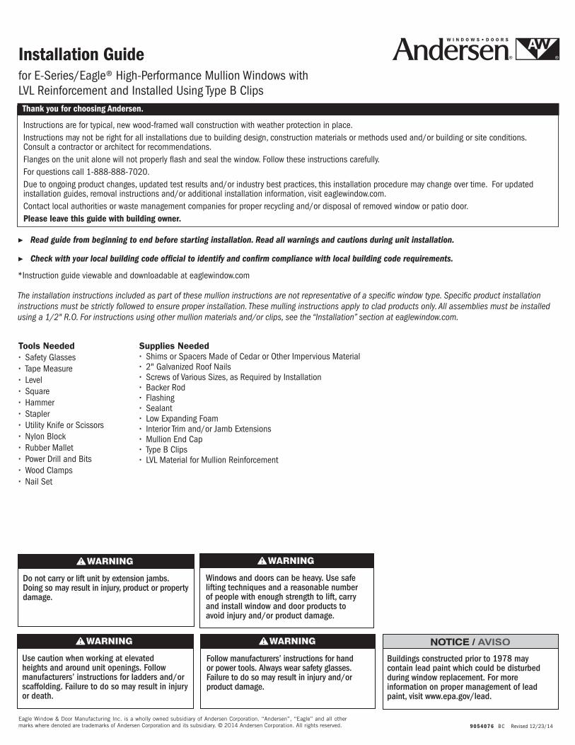
• Apply 3/8" nominal bead of sealant 1-1/2" behind accessory groove on both units. Apply on length of frame and across width at top and bottom.
7. Apply Sealant
8. Measure and Cut LVL Mullion• Measure and cut required length of LVL mullion.
Correct length of reinforcement is equal to length of window.
10. Clamp Mullion to Window
• Align mullion with one window, using wood block to achieve proper setback from exterior face of window.
• Proper setback of mullion from exterior face of cladding is: Casement, awning, auxiliary, double-hung, outswing door, french gliding (sliding) door, patio door - 1-5/16". Inswing door - 2-1/4"
9. Align Mullion
59054076
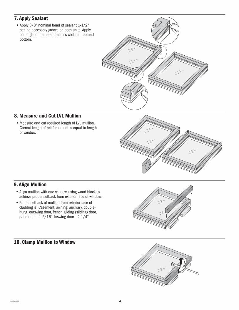
Mullion Fastener ChartsThese tables show the maximum fastener spacing for a #8 wood screw with 1-3/16" penetration into the substrate. Screws must be located 6" from each corner, and as noted in the tables below. If the recommended fastener spacing is longer than the jamb, use two screws per jamb, 6" from each corner.
MaximumDesign
Pressure (psf)
)sehcni( eziS tcudorP)sehcni( eziS tcudorP
24 28 32 36 40 44 48 52 56 60 64 68 72
25 24 24 24 24 24 24 24 24 24 24 24 24 23
50 24 24 24 23 21 19 17 15 15 14 13 12 12
75 23 20 17 15 14 13 12 11 10 9 9 8 8
100 17 15 13 12 10 9 9 8 7 7 6 6 6
24 28 32 36 40 44 48 52 56 60 64 68 72
25 24 24 24 24 24 24 24 24 24 24 24 24 24
50 24 24 24 24 24 24 22 20 19 18 16 16 15
75 24 24 22 20 18 16 15 14 13 12 11 10 10
100 22 19 16 15 13 12 11 10 9 9 8 8 7
MaximumDesign
Pressure (psf)
Fastener spacing (in inches) for double-hung, gliding (sliding) windows, inswing and gliding (sliding) doors
Fastener spacing (in inches) for auxiliary, casement, awning and fixed windows and outswing doors
Note: Use these tables for each dimension. For example, for a 20" x 5'0" casement unit with a DP50, the fastener spacing is 24"
11. Fasten Using Required Screws and Spacing, per Chart Below
ssfhws = Stainless steel flat head wood screwsssts = Stainless steel self tapping screw
Jamb to Rough Opening Fasteners1/4" maximum shim space - use to fill the space and at each screw location2-3/4" recommended screw length for auxiliary, casement, casement fixed, awning windows and outswing doors2-1/4" recommended screw length for double-hung and sliding windows, sliding and inswing doors
Jamb to Mullion Reinforcement FastenersRecommended screw length for auxiliary, casement, casement fixed, awning windows and outswing doors 1" LVL = #8 x 2-1/4" 2" LVL = #8 x 2-1/2"
Recommended screw length for double-hung and sliding windows, sliding and inswing doors 1" LVL = #8 x 1-3/4" 2" LVL = #8 x 2"
Into Into Into 1" LVL Into 2" LVL Into 1" x 3" Into 2" x 4"wood masonry mullion mullion Tube Steel Tube Steelheader header reinforcement reinforcement
Type A Clips #10 x 1-1/2" ssfhws 1/4" x 1-3/4" tapcon #10 x 1" ssfhws #10 x 1-1/2" ssfhws Do not use Do not use
Type B Clips #10 x 1-1/2" ssfhws 1/4" x 1-3/4" tapcon #10 x 1-1/2" ssfhws #10 x 1-1/2" ssfhws #10 x 3/8" sssts #10 x 3/8" sssts
Type F Clips #10 x 1-1/2" ssfhws 1/4" x 1-3/4" tapcon Do not use Do not use Do not use Do not use

69054076
12. Remove Wood Clamps
15. Apply Extension Jamb
13. Align Second Window
14. Fasten Second Window
• Align second window, adjust for proper setback and clamp.
• Fasten second window using required screws and spacing, per chart in step 11.
• Apply extension jamb on interior as necessary.

79054076
16. Apply Installation Flange
17. Apply Sealant to Back (inside) of Installation Flange
18. Install Type B Clip• Locate and install type B clip on each side of
rough opening (top & bottom or left & right). Be sure set-back dimension is correct, as follows:
Use correct fasteners: For header, use #10 x 1-1/2" stainless steel flat head wood screw, or 1/4" x 3/4" tapcon for masonry. For fastening into LVL mullion reinforcement, use #10 x 1-1/2" stainless steel flat head wood screws.
1" x 3-1/2" LVL = 3/4" setback
2” x 3-1/2” LVL = 1/4" setback
• Apply 3/8" nominal bead of sealant over the pre-punched nail holes.
Installation Flange
Interior View
• Apply installation flange into groove on perimeter of windows.
If installing windows from exterior, raised (straight) leg of clip is on interior side. If installing from interior, raised leg is on exterior side.
89054076
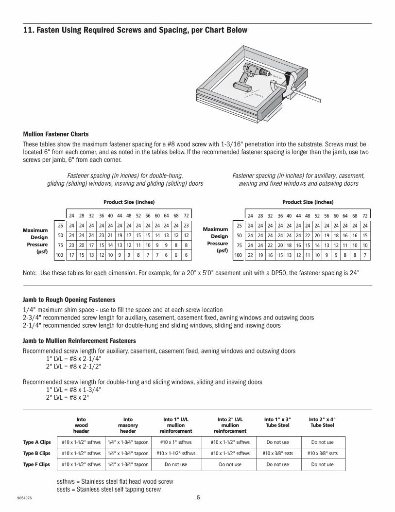
19. Slide Windows into the Rough Opening
20. Shim the Window
21. Fasten the Interior Leg of the Clip
12"
12"
12"
1"
1"
12" 12" 12"1" 1"
12" 12" 12"1" 1"
12"
12"
12"
1"
1"
•Slide window into rough opening and temporarily secure in place.
• Shim the window so it is square, plumb and level.
• Fasten the interior leg of the clip to the mullion using #10 x 1-1/2" stainless steel flat head wood screws.

99054076
22. Bend Exterior Leg of Each Clip Around Mullion and Fasten
23. Drive Screws Through Window Frame into Rough Opening on all Sides of Perimeter
24. Re-apply Stops Using Finish Nails
• Refer to step 11 for correct fastener size.

109054076
25. Apply Interior Mull Cover
26. Apply Nails in Pre-Punched Holes of Nailing Flange
27. Apply Sealant• Apply sufficient sealant to effectively seal the
window and mullion. Tool sealant over entire width of mullion to achieve smooth bead.
• Apply nails in pre-punched holes to effectively secure installation flange over weather-resistant barrier.
119054076
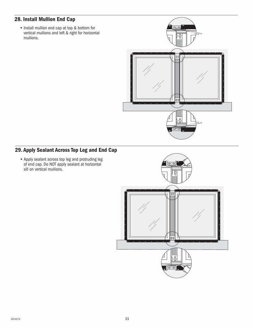
• Install mullion end cap at top & bottom for vertical mullions and left & right for horizontal mullions.
28. Install Mullion End Cap
29. Apply Sealant Across Top Leg and End Cap
• Apply sealant across top leg and protruding leg of end cap. Do NOT apply sealant at horizontal sill on vertical mullions.

129054076
Exterior View
30. Measure Required Length of Exterior Mull Cover and Cut
31. Apply Exterior Mull Cover
• Apply exterior mull cover starting at the bottom right and top left working towards the center using a nylon block and rubber mallet.

139054076
32. Wipe Any Excess Sealant off Both Windows
33. Apply Sealant at mullion ends
• At mullion ends, apply continuous bead of sealant over edge of mullion where it joins the window edge and where the window meets the mullions cap.
34. Apply Sealant in Corners and Around Perimeter
• Apply a sizeable amount of sealant in each corner, and a 3/8" nominal bead of sealant around the perimeter where the installation flange meets the window frame.
149054076
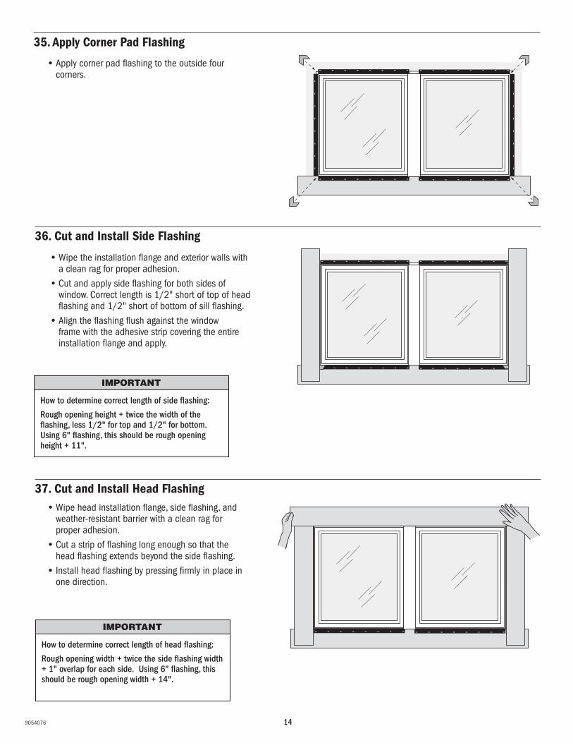
35. Apply Corner Pad Flashing
36. Cut and Install Side Flashing
• Wipe the installation flange and exterior walls with a clean rag for proper adhesion.
• Cut and apply side flashing for both sides of window. Correct length is 1/2" short of top of head flashing and 1/2" short of bottom of sill flashing.
• Align the flashing flush against the window frame with the adhesive strip covering the entire installation flange and apply.
How to determine correct length of side flashing:
Rough opening height + twice the width of the flashing, less 1/2" for top and 1/2" for bottom. Using 6" flashing, this should be rough opening height + 11".
37. Cut and Install Head Flashing• Wipe head installation flange, side flashing, and
weather-resistant barrier with a clean rag for proper adhesion.
• Cut a strip of flashing long enough so that the head flashing extends beyond the side flashing.
• Install head flashing by pressing firmly in place in one direction.
How to determine correct length of head flashing:
Rough opening width + twice the side flashing width + 1" overlap for each side. Using 6" flashing, this should be rough opening width + 14".
• Apply corner pad flashing to the outside four corners.

159054076
38. Apply Metal Drip Cap
• Apply sealant to top edge of back side of drip cap and the head of the window.• Nail drip cap into place so that it covers entire width of joined windows.• Apply sealant in line over nail holes.
Exterior Views

169054076
39. Integrate Flashing System into the Weather-Resistant Barrier
40. Apply Low Expanding Foam
41. Apply Sealant Around Exterior
• Make sure that the flap of the weather-resistant barrier lays flat over the head flashing and lays into the bead of sealant on the head flashing.
• Apply a new piece of flashing over the entire diagonal cut made in the weather-resistant barrier and press into place.
• Apply backer rod and sealant around entire perimeter of window.
• Shape sealant to provide a continuous seal.• Clean of excess sealant.
• From interior of building, insert foam applicator nozzle approximately 1" into space between the window and the rough opening, and apply a 1" deep bed of foam.
• Allow foam to cure completely before proceeding.
Exterior View
Exterior View
Exterior View
When applying siding or other exterior finish material, leave adequate space between the window frame and exterior finish material. See your sealant supplier for recommendations and instructions for these and other applications.
Do not overfill with low expanding foam or over pack with backer rod to avoid bowed jambs.
When applying siding or other exterior finish material, leave adequate space between the window frame and exterior finish material. See your sealant supplier for recommendations and instructions for these and other applications.
179054076
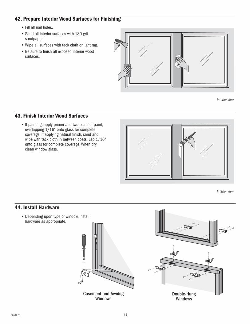
42. Prepare Interior Wood Surfaces for Finishing
43. Finish Interior Wood Surfaces
44. Install Hardware
• Fill all nail holes.• Sand all interior surfaces with 180 grit
sandpaper.• Wipe all surfaces with tack cloth or light rag.• Be sure to finish all exposed interior wood
surfaces.
• Depending upon type of window, install hardware as appropriate.
• If painting, apply primer and two coats of paint, overlapping 1/16" onto glass for complete coverage. If applying natural finish, sand and wipe with tack cloth in between coats. Lap 1/16" onto glass for complete coverage. When dry clean window glass.
Casement and Awning Windows
Double-Hung Windows
Interior View
Interior View

189054076
See the Eagle Owner’s Manual for care and maintenance information.
Methods and procedures for installation of siding and other cladding materials, trim, moldings and other finish materials around window openings are not specified in these instructions. Such materials should be installed in conformity with the manufacturer’s specifications and/or industry standards for such materials. If masonry cladding is used, the soldier course of masonry must be one-half inch away from the bottom of the sill on all windows.
Because all construction must anticipate some water infiltration, it is important that the wall system be designed and constructed to properly manage moisture. Eagle Window & Door is not responsible for claims or damages caused by unanticipated water infiltration, deficiencies in building design, construction and maintenance, failure to install Eagle products in accordance with these instructions, or the use of Eagle products in systems which do not allow for proper management of moisture within the wall system. The determination of the suitability of all building components, including the use of Eagle products, as well as the design and installation of flashing and sealing systems, are the responsibility of you, your architect, or a construction professional. Moisture problems, including unacceptable water infiltration, have been associated with barrier systems such as EIFS (also known as synthetic stucco). Eagle products should not be used in barrier EIFS systems unless Eagle’s current, recommended installation procedures for installation of windows and doors into EIFS are used. Any other use of Eagle products with barrier EIFS systems will void the warranty.
Contact your sealant supplier to choose a sealant that is compatible with, and that will adhere adequately to, all building materials used in the window area. Important: Perimeter sealant must be Grade NS Class 24 per ASTM C920 and compatible with the window/door product, installation flange and the finished exterior of the building. Use of improper sealant could result in sealant failure, resulting in air and water infiltration.
Eagle makes no warranty, expressed or implied, that the methods and procedures described in these instructions are suitable for any particular purpose or installation. These instructions do not add to or modify the terms, conditions or limitations of Eagle’s manufacturer’s warranty.
A drip cap is required on all windows and doors. Failure to utilize and incorporate a drip cap could void the Eagle Window & Door warranty. Refer to the Eagle warranty for additional information.
These installation procedures have been tested by an independent laboratory under ideal installation conditions using the ANSI/AAMA/NWWDA 101/I.S. 2-97 test.


