© 2005 American Honda Motor Co., Inc. - All Rights Reserved. AII 30890 (0509) 1 of 16
INSTALLATIONINSTRUCTIONS
08V31-SVA-1000-91
Accessory Application Publications No.
Issue Date
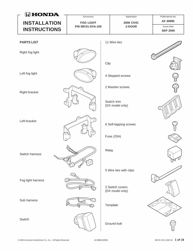
PARTS LIST
FOG LIGHTP/N 08V31-SVA-100
2006 CIVIC2-DOOR
SEP 2005
11 Wire ties
Left fog light
Right bracket
Left bracket
Switch harness
Right fog light
Fog light harness
Sub harness
Clip
4 Stepped screws
2 Washer screws
Switch trim(DX model only)
6 Self-tapping screws
Fuse (20A)
Relay
5 Wire ties with clips
Switch
2 Switch covers(DX model only)
Template
All 30890
Ground bolt

2 of 16 AII 30890 (0509) © 2005 American Honda Motor Co., Inc. - All Rights Reserved.
TOOLS AND SUPPLIES REQUIRED
Phillips screwdriver
Flat-tip screwdriver
Ratchet
10 mm Socket
Drill
3 mm and 10 mm Drill bit
Pushpin
Utility knife
Gloves
Eye protection (face shield, safety goggles, etc.)
File
Masking tape
Scissors
Blanket
Shop towel
6 mm Hexagon wrench
Illustration of Fog Lights installed on the Vehicle
INSTALLATION
Customer Information: The information in thisinstallation instruction is intended for use only byskilled technicians who have the proper tools,equipment, and training to correctly and safely addequipment to your vehicle. These proceduresshould not be attempted by “do-it-yourselfers.”
1. Make sure you have the anti-theft code for theradio, then write down the frequencies for thepreset buttons.
2. Disconnect the negative cable from the battery.
3. Remove the radiator cover (four clips).
FOG LIGHTHARNESS
LEFTFOG LIGHT
SUB HARNESS
RELAY
SWITCH
SWITCHHARNESS
RIGHTFOGLIGHT
5311010T
5311021T
RADIATORCOVER EXPANSION
CLIP
CLIPS (2)• Pull out the clip
vertically from thepanel surface.
PANEL
© 2005 American Honda Motor Co., Inc. - All Rights Reserved. AII 30890 (0509) 3 of 16
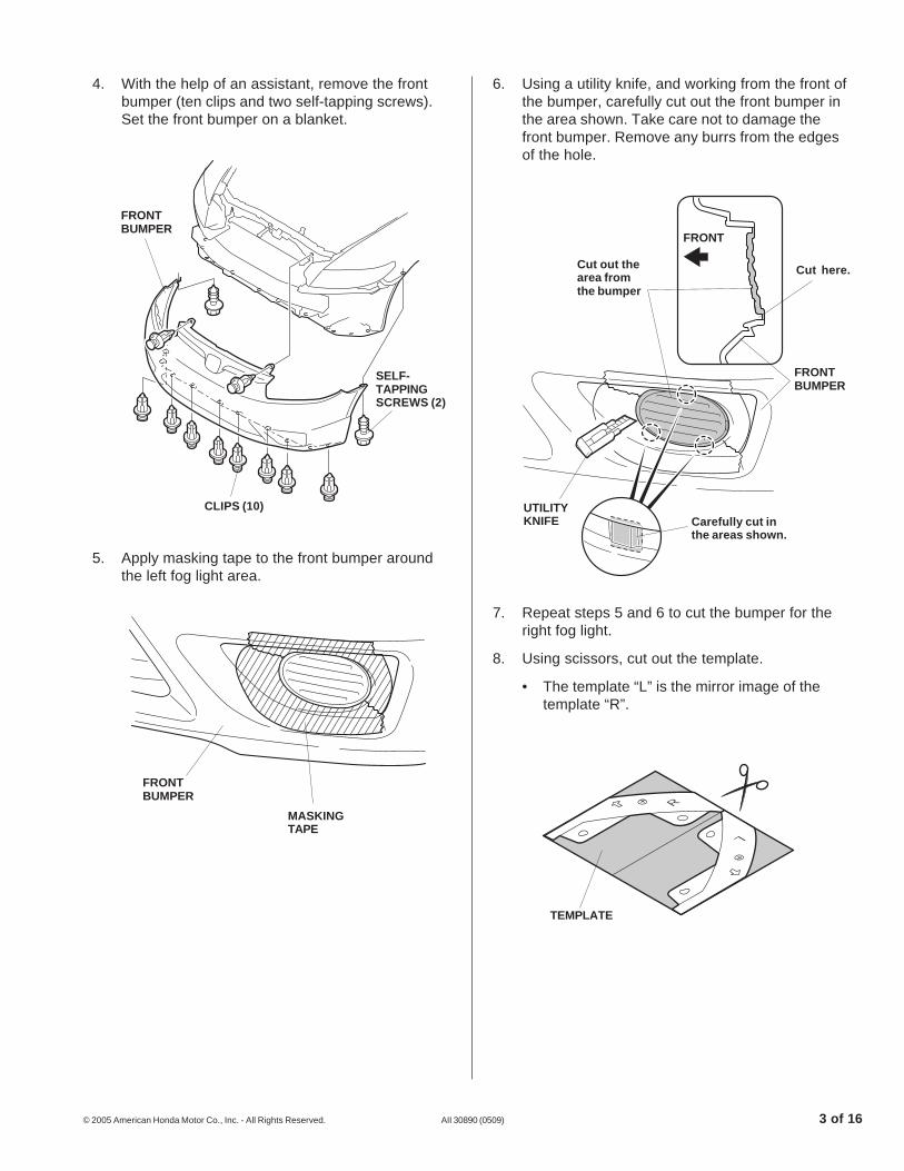
4. With the help of an assistant, remove the frontbumper (ten clips and two self-tapping screws).Set the front bumper on a blanket.
6. Using a utility knife, and working from the front ofthe bumper, carefully cut out the front bumper inthe area shown. Take care not to damage thefront bumper. Remove any burrs from the edgesof the hole.
5311050T
TEMPLATE
5. Apply masking tape to the front bumper aroundthe left fog light area.
5311320T
FRONTBUMPER
MASKINGTAPE
7. Repeat steps 5 and 6 to cut the bumper for theright fog light.
8. Using scissors, cut out the template.
• The template “L” is the mirror image of thetemplate “R”.
5311042T
Cut out thearea fromthe bumper
UTILITYKNIFE
FRONT
FRONTBUMPER
Carefully cut inthe areas shown.
5311032TCLIPS (10)
SELF-TAPPINGSCREWS (2)
FRONTBUMPER
Cut here.
4 of 16 AII 30890 (0509) © 2005 American Honda Motor Co., Inc. - All Rights Reserved.
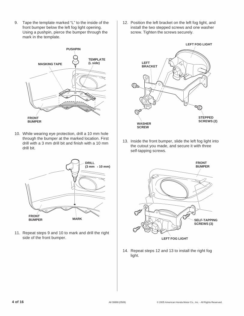
12. Position the left bracket on the left fog light, andinstall the two stepped screws and one washerscrew. Tighten the screws securely.
13. Inside the front bumper, slide the left fog light intothe cutout you made, and secure it with threeself-tapping screws.
10. While wearing eye protection, drill a 10 mm holethrough the bumper at the marked location. Firstdrill with a 3 mm drill bit and finish with a 10 mmdrill bit.
WASHERSCREW
STEPPEDSCREWS (2)
5311080T
LEFT FOG LIGHT
LEFTBRACKET
9. Tape the template marked “L” to the inside of thefront bumper below the left fog light opening.Using a pushpin, pierce the bumper through themark in the template.
11. Repeat steps 9 and 10 to mark and drill the rightside of the front bumper.
14. Repeat steps 12 and 13 to install the right foglight.
5311071T
DRILL(3 mm 10 mm)
MARKFRONTBUMPER
5311091T
SELF-TAPPINGSCREWS (3)
FRONTBUMPER
LEFT FOG LIGHT
5311061T
PUSHPIN
TEMPLATE(L side)MASKING TAPE
FRONTBUMPER
© 2005 American Honda Motor Co., Inc. - All Rights Reserved. AII 30890 (0509) 5 of 16
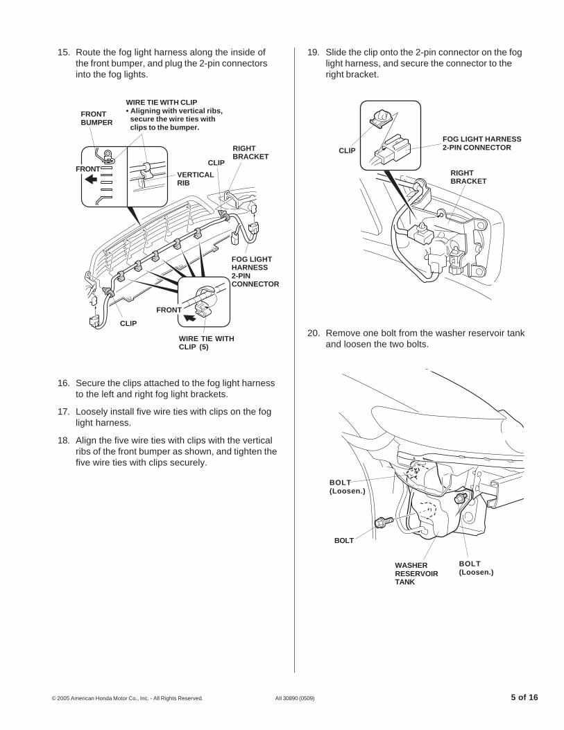
15. Route the fog light harness along the inside ofthe front bumper, and plug the 2-pin connectorsinto the fog lights.
16. Secure the clips attached to the fog light harnessto the left and right fog light brackets.
17. Loosely install five wire ties with clips on the foglight harness.
18. Align the five wire ties with clips with the verticalribs of the front bumper as shown, and tighten thefive wire ties with clips securely.
19. Slide the clip onto the 2-pin connector on the foglight harness, and secure the connector to theright bracket.
20. Remove one bolt from the washer reservoir tankand loosen the two bolts.
5311110T
CLIP
FOG LIGHT HARNESS2-PIN CONNECTOR
RIGHTBRACKET
5307112T
WASHERRESERVOIRTANK
BOLT(Loosen.)
BOLT(Loosen.)
BOLT
5311102T
RIGHTBRACKET
FOG LIGHTHARNESS2-PINCONNECTOR
CLIP
CLIP
FRONT
FRONTBUMPER
WIRE TIE WITHCLIP (5)
WIRE TIE WITH CLIP• Aligning with vertical ribs,
secure the wire ties withclips to the bumper.
VERTICALRIB
FRONT

6 of 16 AII 30890 (0509) © 2005 American Honda Motor Co., Inc. - All Rights Reserved.
24. Secure the two clips on the subharness to thevehicle frame. Secure the subharness to thevehicle harness using two wire ties.
25. Reinstall the washer reservoir tank.
26. Plug the 2-pin connector on the subharness intothe 2-pin connector on the fog light harness.
27. Reinstall the front bumper.
5311140T
FRONTBUMPER
FOG LIGHTHARNESS2-PINCONNECTOR
SUB HARNESS2-PIN CONNECTOR
21. Locate the 1-pin connector blue-taped to thevehicle harness, and remove the blue tape to freethe 1-pin connector. Plug the 1-pin connector youjust freed into the 1-pin connector from thesubharness.
22. Route the subharness between the washerreservoir tank and vehicle panel, and route it asshown.
23. Secure the subharness ground terminal to thevehicle frame using a ground bolt.
5307121T
VEHICLEHARNESS
1-PINCONNECTORS
BLUE TAPE(Remove.)
SUB HARNESS
SUBHARNESS
GROUNDTERMINAL
5311301T
WASHERRESERVOIRTANK
VEHICLEFRAME
VEHICLEPANEL GROUND
BOLT
5311131T
WIRETIE
CLIP
SUB HARNESS
VEHICLEFRAME

© 2005 American Honda Motor Co., Inc. - All Rights Reserved. AII 30890 (0509) 7 of 16
28. Remove the cover from the trunk lid/fuel fill dooropener (six retaining tabs), and remove one self-tapping screw.
29. Using the ignition key, unlock the opener.
30. Raise the front edge of the left front door silltrim (six clips, retaining tab, and hook).
5202191T
KEY
OPENERLOCKCYLINDER
SELFTAPPINGSCREW
COVERRETAININGTABS (6)
TRUNK LID/FUEL FILLDOOR OPENER
31. Remove the footrest.
• Using a hexagon wrench, remove the lowerclip from the stud bolt.
• Using a flat-tip screwdriver, remove the upperclip from the stud bolt.
32. Pull away the weatherstrip from the left kick paneland remove the left kick panel (two clips).
5202220T
WEATHERSTRIPCLIPS(2)
LEFTKICKPANEL
5311370T
STUD BOLT
UPPERCLIP
FOOTRESTLOWERCLIP
HEXAGONWRENCH
LEFT FRONTDOOR SILL TRIM
FRONT
5311351T
CLIPS (6)
RETAININGTAB
HOOK

8 of 16 AII 30890 (0509) © 2005 American Honda Motor Co., Inc. - All Rights Reserved.
34. Remove the driver’s dashboard lower cover (eightclips).
5202121T
DRIVER’SDASHBOARDLOWER COVER
CLIPS (8)
DX model: Continue with step 35.All other models: Go to step 38.
35. Lower the tilt/telescopic lever, and move thesteering wheel down and toward you. Aftermoving the steering wheel, return the tilt/telescopic lever to its original position.
33. If equipped, remove the driver’s dashboard undercover (turn the lock knob 90° counterclockwise,and release the two clips and pin).
5202112T
CLIPS (2)
DRIVER’SDASHBOARDUNDER COVER
KNOB
36. Cover the combination switch with a shop towelto protect it from damage.
5831010H
TILT/TELESCOPICLEVER
STEERINGWHEEL
SHOP TOWEL
COMBINATIONSWITCH
© 2005 American Honda Motor Co., Inc. - All Rights Reserved. AII 30890 (0509) 9 of 16
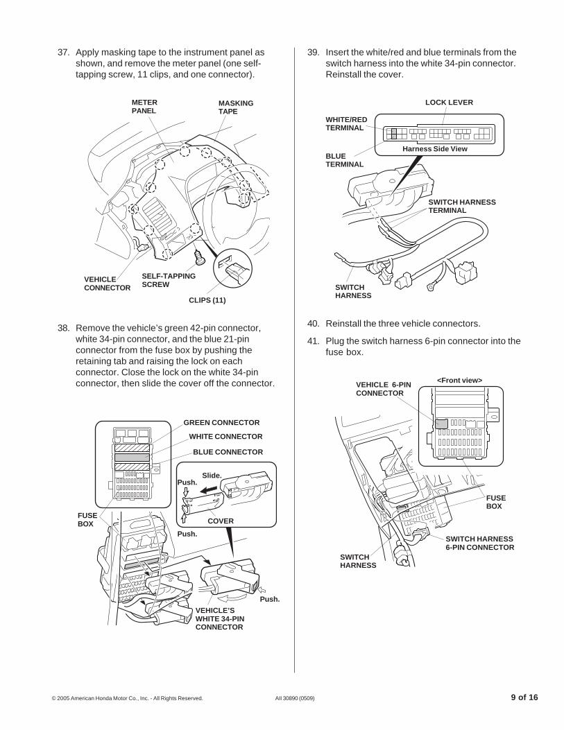
39. Insert the white/red and blue terminals from theswitch harness into the white 34-pin connector.Reinstall the cover.
40. Reinstall the three vehicle connectors.38. Remove the vehicle’s green 42-pin connector,white 34-pin connector, and the blue 21-pinconnector from the fuse box by pushing theretaining tab and raising the lock on eachconnector. Close the lock on the white 34-pinconnector, then slide the cover off the connector.
37. Apply masking tape to the instrument panel asshown, and remove the meter panel (one self-tapping screw, 11 clips, and one connector).
5311150T
WHITE/REDTERMINAL
BLUETERMINAL
Harness Side View
SWITCH HARNESSTERMINAL
SWITCHHARNESS
LOCK LEVER
5307163T
FUSEBOX COVER
Push.
GREEN CONNECTOR
WHITE CONNECTOR
BLUE CONNECTOR
Slide.
VEHICLE’SWHITE 34-PINCONNECTOR
Push.
Push.
41. Plug the switch harness 6-pin connector into thefuse box.
5311160T
<Front view>
FUSEBOX
VEHICLE 6-PINCONNECTOR
SWITCH HARNESS6-PIN CONNECTOR
SWITCHHARNESS
CLIPS (11) 5624100B
SELF-TAPPINGSCREW
MASKINGTAPE
METERPANEL
VEHICLECONNECTOR
10 of 16 AII 30890 (0509) © 2005 American Honda Motor Co., Inc. - All Rights Reserved.
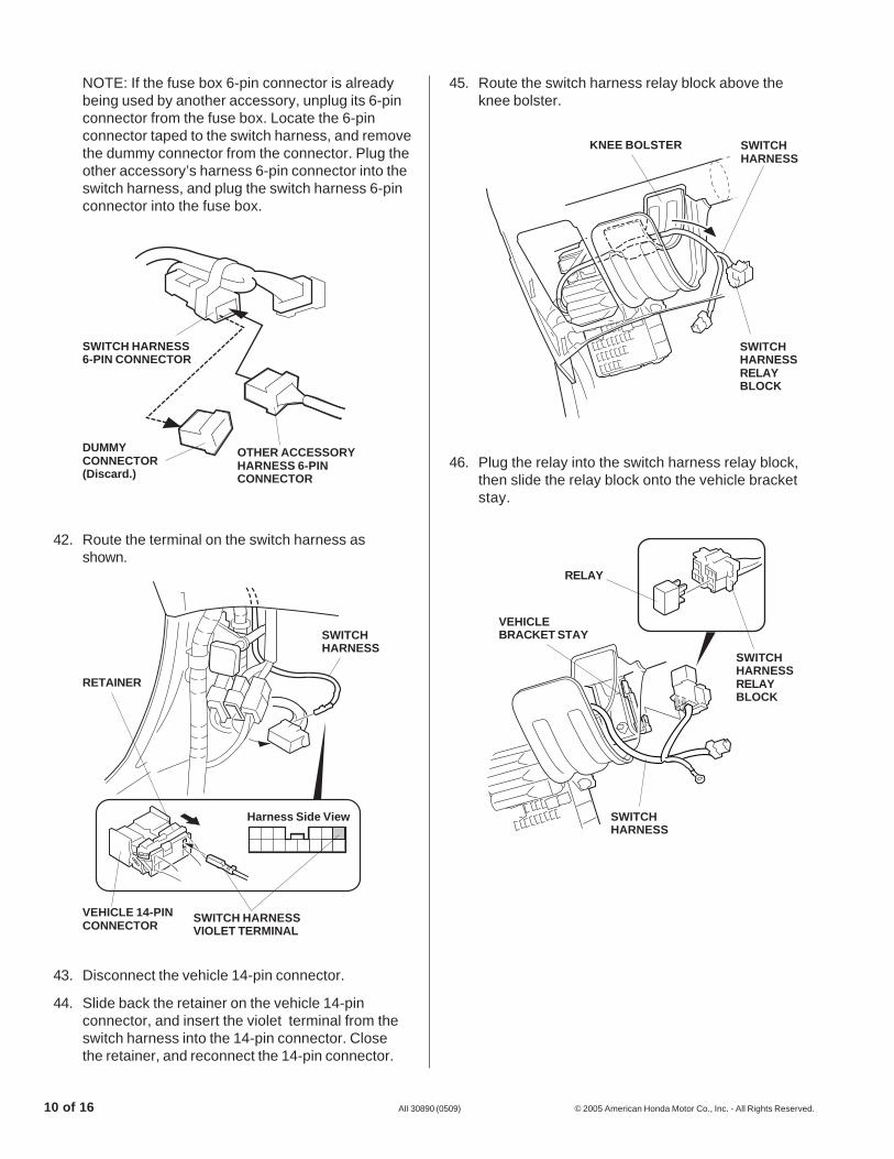
46. Plug the relay into the switch harness relay block,then slide the relay block onto the vehicle bracketstay.
5307190T
RELAY
VEHICLEBRACKET STAY
SWITCHHARNESSRELAYBLOCK
SWITCHHARNESS
NOTE: If the fuse box 6-pin connector is alreadybeing used by another accessory, unplug its 6-pinconnector from the fuse box. Locate the 6-pinconnector taped to the switch harness, and removethe dummy connector from the connector. Plug theother accessory’s harness 6-pin connector into theswitch harness, and plug the switch harness 6-pinconnector into the fuse box.
42. Route the terminal on the switch harness asshown.
43. Disconnect the vehicle 14-pin connector.
44. Slide back the retainer on the vehicle 14-pinconnector, and insert the violet terminal from theswitch harness into the 14-pin connector. Closethe retainer, and reconnect the 14-pin connector.
5311170T
SWITCHHARNESS
SWITCH HARNESSVIOLET TERMINAL
Harness Side View
VEHICLE 14-PINCONNECTOR
RETAINER
45. Route the switch harness relay block above theknee bolster.
5311310T
DUMMYCONNECTOR(Discard.)
SWITCH HARNESS6-PIN CONNECTOR
OTHER ACCESSORYHARNESS 6-PINCONNECTOR
KNEE BOLSTER SWITCHHARNESS
5307180T
SWITCHHARNESSRELAYBLOCK

© 2005 American Honda Motor Co., Inc. - All Rights Reserved. AII 30890 (0509) 11 of 16
48. Locate the 1-pin connector blue-taped to thevehicle harness. Plug the 1-pin connector into theswitch harness 1-pin connector.
5306260T
SELF-TAPPINGSCREW
POCKET(Discard.)
METERPANEL
47. Remove the vehicle ground bolt. Install the switchharness ground terminal, then reinstall the groundbolt.
5311200T
SWITCHHARNESS
VEHICLEGROUNDBOLT (Reuse.)
SWITCH HARNESSGROUND TERMINAL
FRONT
49. Install the fog light switch:
DX Model
• Remove the pocket from the meter panel (threeself-tapping screws).
5311212TSWITCHHARNESS
1-PINCONNECTOR
• Install the switch trim to the meter panel with thethree self-tapping screws.
5311220T
SELF-TAPPINGSCREW(Reuse.) METER
PANEL
SWITCH
SWITCHCOVER
SWITCHTRIM
SWITCHCOVER
• Install the switch and two switch covers into theswitch trim.
12 of 16 AII 30890 (0509) © 2005 American Honda Motor Co., Inc. - All Rights Reserved.
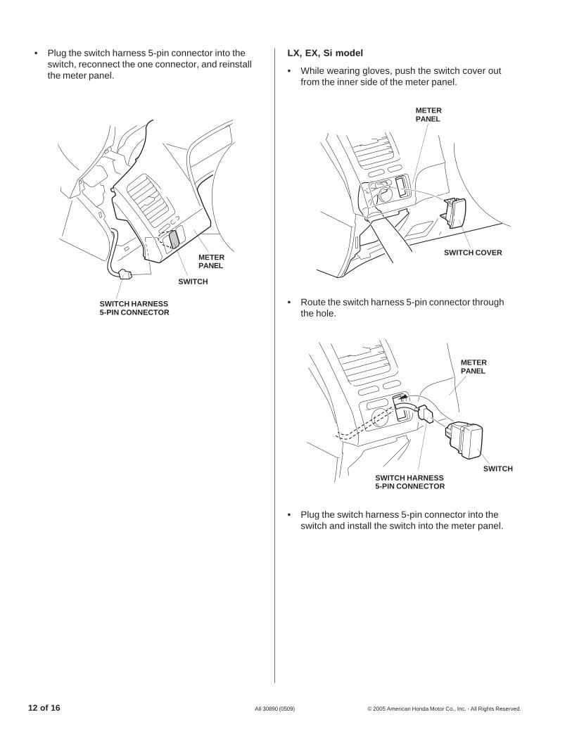
• Plug the switch harness 5-pin connector into theswitch, reconnect the one connector, and reinstallthe meter panel.
5311230T
SWITCH HARNESS5-PIN CONNECTOR
SWITCH
METERPANEL
LX, EX, Si model
• While wearing gloves, push the switch cover outfrom the inner side of the meter panel.
• Route the switch harness 5-pin connector throughthe hole.
• Plug the switch harness 5-pin connector into theswitch and install the switch into the meter panel.
5311330T
METERPANEL
SWITCH COVER
5311340T
SWITCH
METERPANEL
SWITCH HARNESS5-PIN CONNECTOR

© 2005 American Honda Motor Co., Inc. - All Rights Reserved. AII 30890 (0509) 13 of 16
50. Secure the switch harness to the vehicle harnessand to the knee bolster with nine wire ties in theareas shown.
51. Install the 20A fuse into the fuse box in thelocation shown.
52. Check that all wire harnesses are routed properlyand all connectors are plugged in.
53. Reinstall all removed parts.
54. Reconnect the negative cable to the battery.
USE AND CARE
How to Operate the Fog Lights
• Turn the light switch to the “ ” position(headlights on low beam).
• Press the fog light switch (indicator is on).
NOTE: The fog light lenses can cloud when theoutside temperature is cold; this is normal and shouldgo away in warm weather.
Fog Light Aiming Adjustment
55. Adjust the fog light:
• Adjust the aim according to local laws andregulations.
• To adjust, turn the aiming adjustment knob inor out until the correct aim is obtained.
5307240T
<Front View>
FUSELOCATION“6”
20 AFUSE
FUSEBOX
5311242T
VEHICLEHARNESS
WIRE TIES (9)
KNEE BOLSTER
SWITCHHARNESS
5311251TTo raiseTo lower
AIMINGADJUSTMENTSCREW
14 of 16 AII 30890 (0509) © 2005 American Honda Motor Co., Inc. - All Rights Reserved.
56. Reset the clock, and reset the radio stationpresets.
NOTE: Whenever the battery is disconnected, thedriver’s AUTO function is disabled.
57. Start the engine. Push down on the driver’swindow switch until the window is fully open.
58. Pull up on the driver’s window switch fully to closethe window completely, then hold the switch for 2seconds or more.
59. Test the window AUTO function.
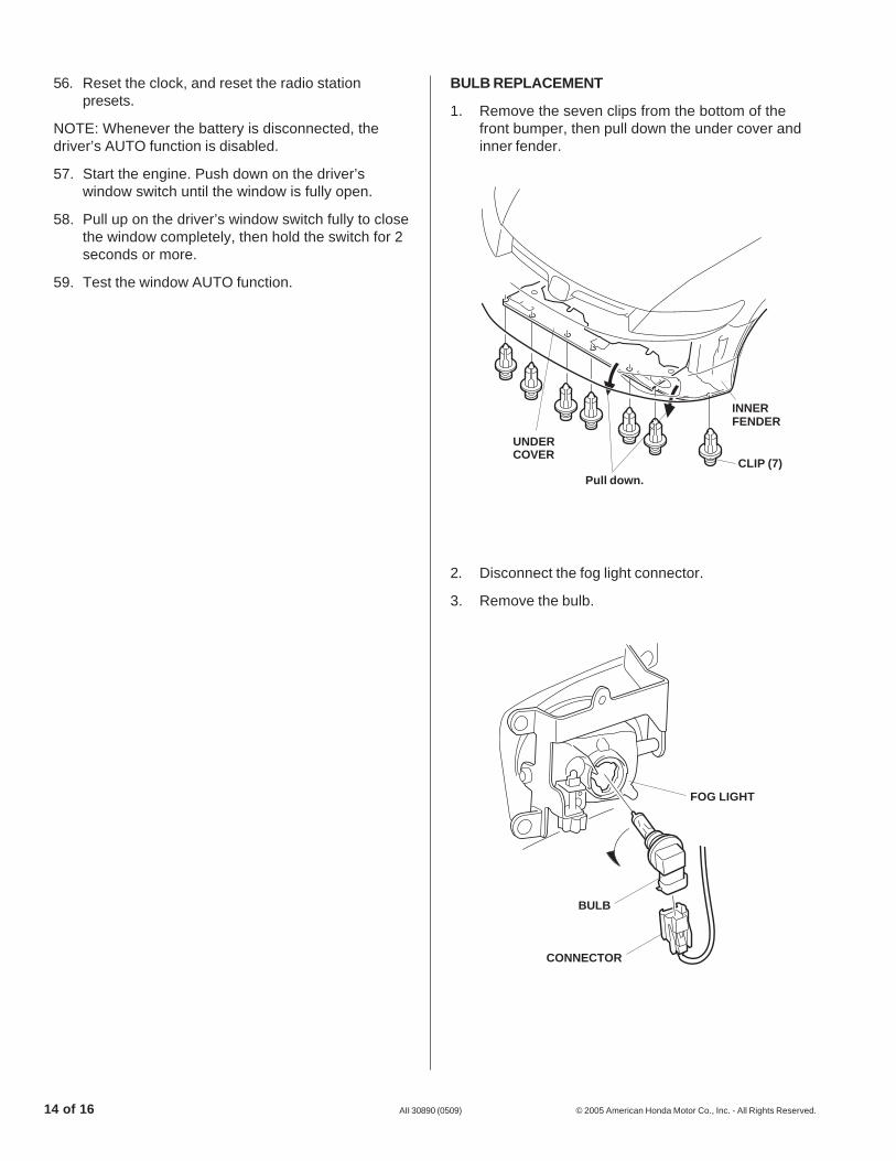
2. Disconnect the fog light connector.
3. Remove the bulb.
BULB REPLACEMENT
1. Remove the seven clips from the bottom of thefront bumper, then pull down the under cover andinner fender.
5311270T
FOG LIGHT
CONNECTOR
BULB
5311262T
CLIP (7)Pull down.
INNERFENDER
UNDERCOVER
© 2005 American Honda Motor Co., Inc. - All Rights Reserved. AII 30890 (0509) 15 of 16
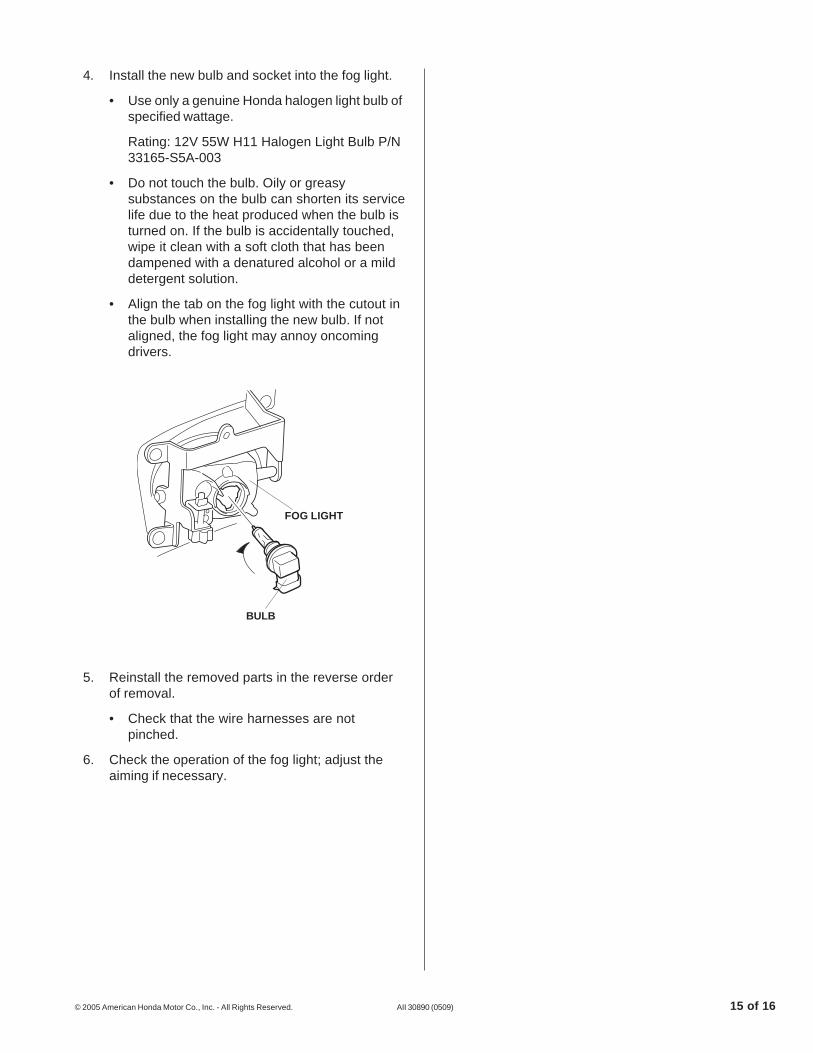
4. Install the new bulb and socket into the fog light.
• Use only a genuine Honda halogen light bulb ofspecified wattage.
Rating: 12V 55W H11 Halogen Light Bulb P/N33165-S5A-003
• Do not touch the bulb. Oily or greasysubstances on the bulb can shorten its servicelife due to the heat produced when the bulb isturned on. If the bulb is accidentally touched,wipe it clean with a soft cloth that has beendampened with a denatured alcohol or a milddetergent solution.
• Align the tab on the fog light with the cutout inthe bulb when installing the new bulb. If notaligned, the fog light may annoy oncomingdrivers.
5. Reinstall the removed parts in the reverse orderof removal.
• Check that the wire harnesses are notpinched.
6. Check the operation of the fog light; adjust theaiming if necessary.
BULB
FOG LIGHT
5311280T
16 of 16 AII 30890 (0509) © 2005 American Honda Motor Co., Inc. - All Rights Reserved.
5311292T
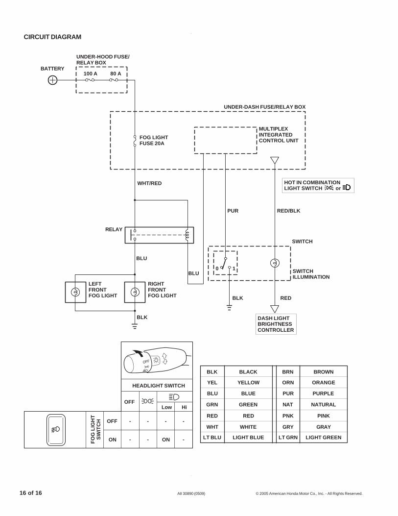
MULTIPLEXINTEGRATEDCONTROL UNIT
UNDER-DASH FUSE/RELAY BOX
RED/BLK
0 1
PUR
BLU
BLU
BLK
RELAY
WHT/RED
FOG LIGHTFUSE 20A
HEADLIGHT SWITCH
Low HiOFF
ONFO
G L
IGH
TS
WIT
CH OFF - - - -
BLK BRN BROWNBLACK
YEL ORN ORANGEYELLOW
BLU PUR PURPLEBLUE
GRN NAT NATURALGREEN
RED PNK PINKRED
WHT GRY GRAYWHITE
LT BLU LT GRN LIGHT GREENLIGHT BLUE- - -ON
UNDER-HOOD FUSE/RELAY BOX
BATTERY100 A 80 A
RIGHTFRONTFOG LIGHT
LEFTFRONTFOG LIGHT
SWITCHILLUMINATION
BLK RED
DASH LIGHTBRIGHTNESSCONTROLLER
HOT IN COMBINATIONLIGHT SWITCH or
SWITCH
CIRCUIT DIAGRAM


