EN
www.ammeraalbeltech.com
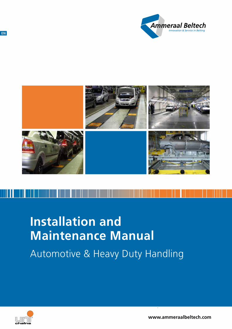
Installation and Maintenance ManualAutomotive & Heavy Duty Handling
Installation and Maintenance Manual
Page 2
Table of ContentsSafety Guidelines for Our Conveyor Belts 3
Storage of Plastic Modular Belts 3
Safety Equipment on Our Conveyor Belts 4
General Safety Instructions 4
Possible Hazards and Safety Risks 5
The Products You Received 6
uni XLB 6
uni CPB M2 10
uni CSB 12
uni ACB 16
Installation of Shafts and Sprockets 19
Carryway Configuration 20
Belt Installation on Carryway 20
General Procedure 21
Belt Installation on the Returnway 21
Installation Check 22
Catenary Sag 22
Run-in Time 22
Wide and Long Conveyors 23
Preventive Maintenance and Troubleshooting 24
What Should Be Reported to Your Maintenance Department? 24
Troubleshooting 25
1 The drive sprockets do not engage with the belt 25
2 The belt is not tracking properly 25
3 Excessive wear of the belt 26
4 Excessive wear of the sprockets 26
5 Excessive wear or damages of the belt edges 27
6 The sprockets move laterally to the center or to the edge of the belt 28
7 Wear or damages of the sideguards (including breakage) 28
8 Wear or damages of the drivers/ dogs 28
9 Excessive catenary sag at the belt 29
Maintenance 29
Your Contact Partners 29

Installation and Maintenance Manual
Page 3
Safety Guidelines for Our Conveyor BeltsAs a standard, our conveyor belts are designed with particular attention to safety Unnecessary hazards have to be avoided when handling and using conveyor belts For this reason, many design features have deliberately been selected in such a way, that the injury hazards for personnel being charged to handle and operate our belts are minimized The regulations on the prevention of accidents for continuous conveyors (VBG 10), and in particular the paragraphs 5, 12, 53, 54 and 55, have to be carefully observed
Storage of Plastic Modular Belts Warning: Do not expose the products to direct sun light
Warning: Do not expose the modules to extreme temperatures
Danger: Ignited plastic may generate poisonous smoke
Warning: Do not expose belts to any chemical substances with a ph-value of less than 4 5 or higher than 9 0

Installation and Maintenance Manual
Page 4
Safety Equipment on Our Conveyor Belts One of the most frequent kinds of accidents in relation to conveyor belts is the injury of parts of the body that get caught in between the moving modular belt and the rotating rollers/ sprockets To avoid such accidents or to minimize these risks as far as possible, all the conveyor belts have to be equipped with protective devices to cover any gaps and clearances in all those locations where the plastic belt runs on a roller, drum or sprocket This protection has to be designed in such a manner that it re-locates its position during adjustment operations, and thus always remains in the correct position in relation to the sprocket/ roller In order to prevent damages of electric devices and to minimize the danger of electric shocks, all our conveyor belts have to be connected to ground in all parts Every conveyor belt must be equipped with a circuit-breaker which automatically switches off the unit in case of overload or overheating It is also possible to fit one or more emergency out-switches to switch off the conveyor belt if danger is imminent
General Safety Instructions
Caution: Wear safety shoes
Danger: Wear protective goggles
Warning: Wear protective gloves
Caution: Prevent accidents
Attention: Only use suitable tools that are in good condition
Installation and Maintenance Manual
Page 5
Possible Hazards and Safety Risks We expressly draw your attention to the following hazards being in the nature of things when using belt conveyors:
Risk of injuries by the frame
The constructional design makes it inevitable to have edges and corners on the conveyor where the risk of injury exists due to inattentiveness
Risk of injuries by the plastic modular belt
The movement of the plastic modular belt may cause serious gashes and bruises if the running conveyor is touched
Risk of injuries by moving parts
In general, all the moving parts of a running machine present a risk of injuries
Injuries due to electricity
During the operation of the machine, the mechanical parts are live Injuries due to electric current may still be possible up to 90 seconds after having disconnected the equipment from the mains Injuries due to electricity are only excluded after this time
Destruction of the plastic modular belt
Destruction of the plastic modular belt may be possible if it is not checked and inspected from time to time, and if occurring defects are not corrected immediately The plastic modular belt may also be damaged and destructed by the products transported on it
Fire hazard due to overload and jamming
If the conveyor belt is not properly protected against overload or when it is connected to electric current, the motor may catch fire
In many cases, the particular operation conditions of the conveyor may require special measures These may be provided by us or by the operator himself Please contact uni-chains if you need assistance in this respect
Installation and Maintenance Manual
Page 6
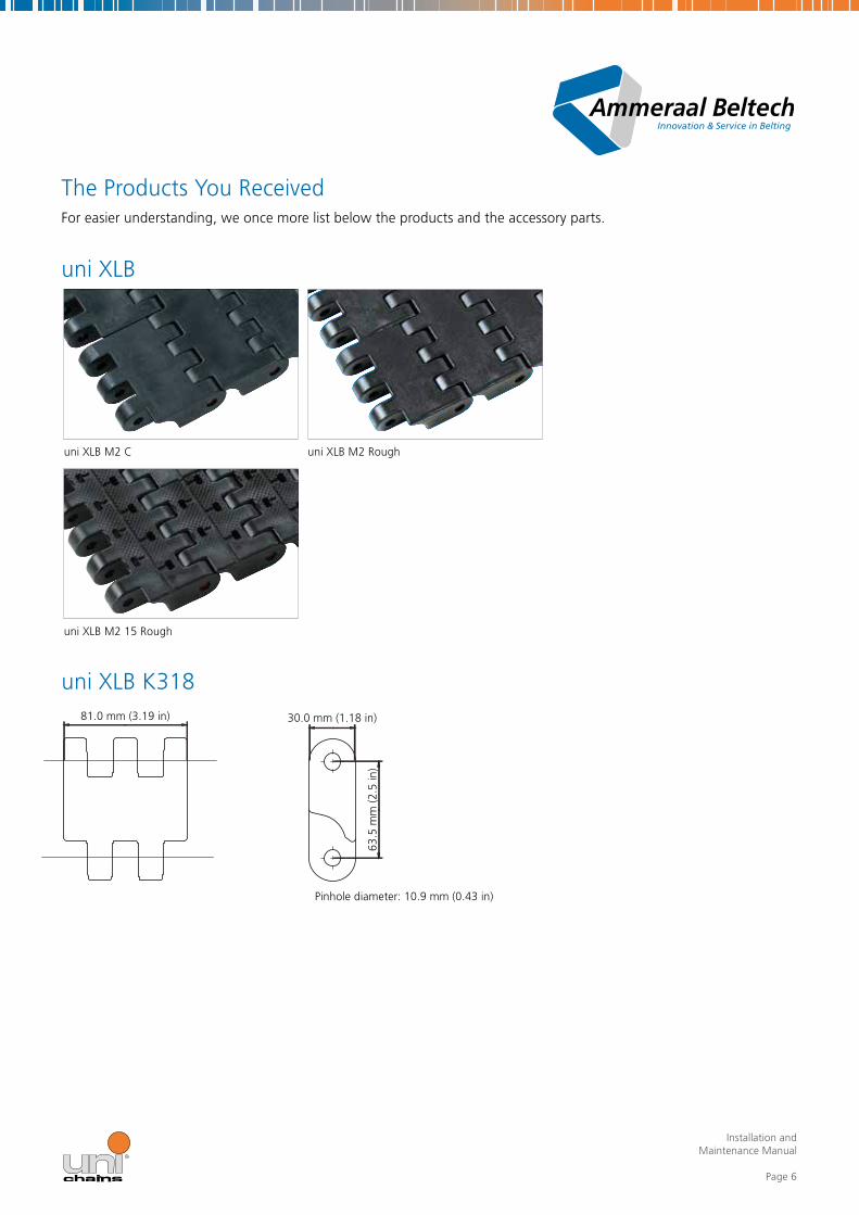
30 0 mm (1 18 in)
Pinhole diameter: 10 9 mm (0 43 in)
uni XLB M2 C
uni XLB M2 15 Rough
uni XLB M2 Rough
81 0 mm (3 19 in)
63 5
mm
(2 5
in)
The Products You ReceivedFor easier understanding, we once more list below the products and the accessory parts
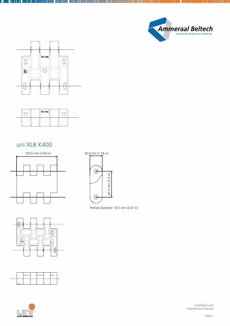
uni XLB
uni XLB K318
Installation and Maintenance Manual
Page 7
uni XLB K40030 0 mm (1 18 in)
Pinhole diameter: 10 5 mm (0 41 in)
100 0 mm (3 94 in)
63 5
mm
(2 5
in)

Installation and Maintenance Manual
Page 8
200 4 mm (7 89 in)
uni XLB K80030 0 mm (1 18 in)
Pinhole diameter: 10 5 mm (0 41 in)
63 5
mm
(2 5
in)
Installation and Maintenance Manual
Page 9
33 0
mm
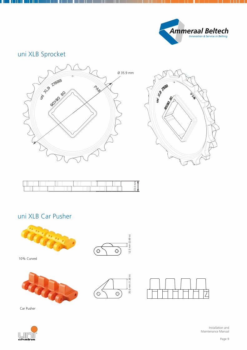
uni XLB Sprocket
uni XLB Car Pusher
Ø 35 9 mm
10% Curved
Car Pusher
35 0
mm
(1 3
8 in
)12
5 m
m (0
49
in)

Installation and Maintenance Manual
Page 10
151 0 mm (5 94 in)
50 8
mm
(2 0
in)
50 8
mm
(2 0
in)
19 0 mm (0 75 in) 20 0 mm (0 79 in)
uni CPB M2
uni CPB M2 C
uni CPB M2 C uni CPB M2 Rough
uni CPB M2 Rough uni CPB 20% Rough
Pinhole diameter: 8 3 mm (0 33 in)
Installation and Maintenance Manual
Page 11
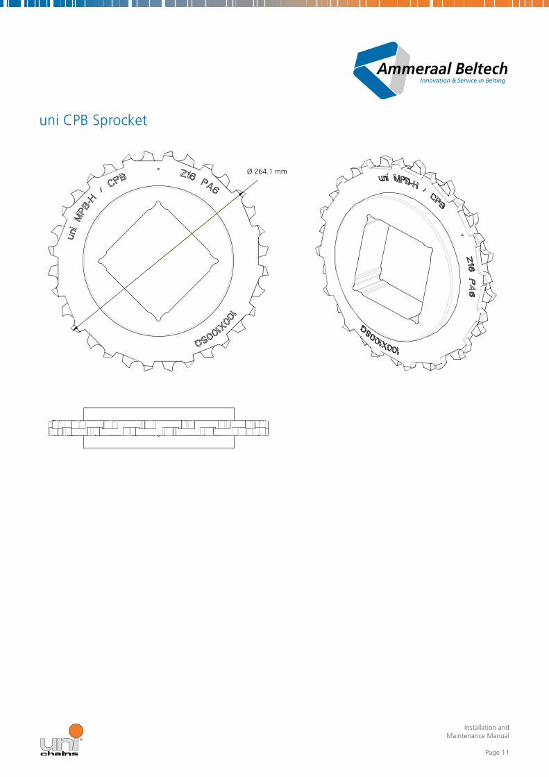
Ø 264 1 mm
uni CPB Sprocket

Installation and Maintenance Manual
Page 12
24 0 mm (0 94 in)
uni CSB C uni CSB Roughuni CSB 8%
50 8
mm
(2 0
0 in
)
152 0 mm (5 98 in)
Pinhole diameter: 8 4 mm (0 33 in)
uni CSB
uni CSB K600

Installation and Maintenance Manual
Page 13
uni CSB K1200
24 0 mm (0 94 in)
50 8
mm
(2 0
0 in
)
304 4 mm (11 97 in)

Installation and Maintenance Manual
Page 14
144 1 mm (5 67 in) 50 8 mm (2 00 in)
uni CSB Top Bottom Insert Wheel Plate
uni CSB Top Bottom Insert Electrical Conductive
144 1 mm (5 67 in) 50 8 mm (2 00 in)
Installation and Maintenance Manual
Page 15
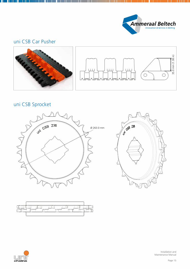
uni CSB Sprocket
Ø 263 0 mm
35 0
mm
(1 3
8 in
)
uni CSB Car Pusher
Installation and Maintenance Manual
Page 16
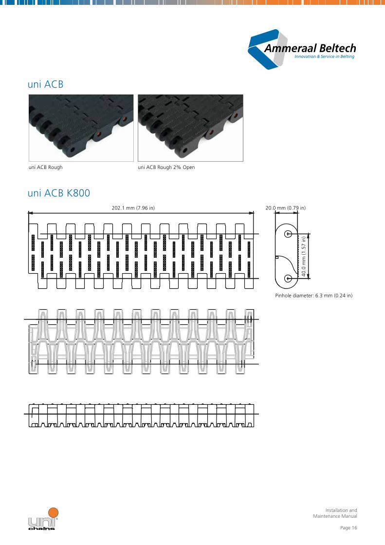
uni ACB Rough uni ACB Rough 2% Open
Pinhole diameter: 6 3 mm (0 24 in)
uni ACB
uni ACB K80020 0 mm (0 79 in)202 1 mm (7 96 in)
40 0
mm
(1 5
7 in
)
Installation and Maintenance Manual
Page 17
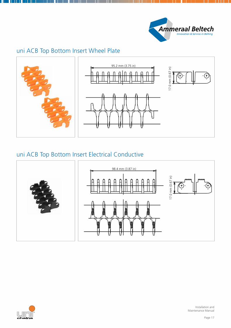
uni ACB Top Bottom Insert Wheel Plate
uni ACB Top Bottom Insert Electrical Conductive
95 2 mm (3 75 in)
98 4 mm (3 87 in)17
0 m
m (0
67
in)
17 0
mm
(0 6
7 in
)

Installation and Maintenance Manual
Page 18
n 205.0
n 205.0
n 205.0
uni ACB Car Pusher
n 205 0
uni ACB Sprocket
35 0
mm
(1 3
8 in
)

Installation and Maintenance Manual
Page 19
Installation of Shafts and SprocketsInstallation and alignment of shafts
Sprockets are preferably locked on the outside of the outer sprockets with the same amount of play as the belt has to the side guides The shafts have to be aligned in a level manner and one shaft behind the other The locked sprockets ensure proper tracking of the belt along the complete conveyor They are aligned to each other in the same way over the entire length of the conveyor If the shafts are not precisely positioned to each other, proper tracking may be adversely affected
Alignment of sprockets
Take care for correct alignment of the teeth when fitting the sprockets onto square shafts If the number of teeth of a sprocket with square bore can evenly be divided by 4, with no remainder, the teeth are automatically correctly aligned, irrespective of how the sprockets are fitted to the square shaft (for example: 16 ÷ 4 = 4) However, if there is a remainder, particular attention has to be paid to the correct alignment of the sprockets In this case, all the sprockets are provided with a plumb bore When fitting the sprockets, all these bores have to be radially flush and one after the other
The sprockets are lined up on the shaft without any distance In axial direction, the sprockets are fixed with appropriate means at the outer ends only, so that a certain axial moveability is allowed

Installation and Maintenance Manual
Page 20
Carryway ConfigurationIn dry and clean environments, the belt supports are preferably out of uni-chains Unicon material since in most applications supports capable of electro-dynamic suspension (EDS) is required In very wet conditions the use of stainless steel supports with drainage openings is the best choice For conditions which are partially wet and/or not clean, please consult uni-chains
Wearstrips
Bring each wearstrip profile in the correct position In most cases, it is sufficient to bevel cut the opposing ends of the wearstrip profiles at an angle of 15° and to leave a gap of about 8 mm Under extreme conditions, the angle should amount to 60° The required width of the gap must be determined on basis of the thermal expansion calculations To ensure smooth belt running, the joint locations of the wearstrip profiles should be staggered Start at the idle end of the conveyor
With the installation of sliding sheets side guides or sliding strips it must be assured that at no time these components are exposed to; abrasive dust such as concrete dust during building work or construction operations, welding or grinding particles, corrosion residue, non-approved chemicals by Ammeraal Beltech which may damage the conveyor materials, impacts or mechanical damage, UV light or exposure to fire
In the period between mounting the sliding components and the conveyor belt we strongly recommend covering these surfaces with plastic sheeting or other suitable cover to protect these from dirt and debris
Proper cleaning of the sliding components is needed, prior to integration of the conveyor belt into the conveyor system and onto the sliding sheets, whenever any form of dirt could be in contact with before mentioned components to avoid increased wear of belt and/or sliding sheets
Belt Installation on CarrywayPreparatory Work
This manual contains general recommendations and instructions for the installation of uni-chains conveyor belts Please pay attention to the differences between the individual conveyor types The particularities of each conveyor frame and of each application have to be duly considered The following points must be observed in any case, irrespective of whether you install a new belt or whether you replace an existing one:
1 In case of retrofits, you may use the same carryways for the uni-chains belts as have been used hitherto The carry ways have to be clean and in a good condition They should be free from grooves or wear and from any damages on the surface
2 Check whether the material of the wearstrips is compatible with the material of the new belt
3 If required, replace the wearstrips
Please consult uni-chains, should you need further assistance in this respect

Installation and Maintenance Manual
Page 21
General Procedure1 If a shaft take-up is installed, relax the same completely
2 Feed the belt from the drive side of the conveyor through the carryway
3 Fit the belt around the idle sprockets Take care that the sprockets do not change their position
4 For wide belts, make sure that the supplied sections are transported in a suitable manner
5 Do not throw the belt sections onto the carryway The non-observance of this instruction may result in the destruction of individual modules
6 Center the belt in the conveyor frame Pay attention to the location of the locked sprocket, and provide for sufficient distance between the belt edges and the conveyor frame, so that the belt may expand freely This is of particular importance for applications involving considerable temperature fluctuations
Belt Installation on the Returnway1 Feed the belt through the returnway until the drive sprockets are reached
2 Fit the belt around the drive sprockets Take care that the locked sprockets do not change their position Make sure that belt meshes with the locked sprocket at the drive end in the same position as on the idle end The non-observance of this instruction may lead to poor belt tracking
3 Connect the belt sections Take care that the edges are properly aligned
4 Fitting the connecting rods is facilitated by bevel cutting the rods
5 Insert the connecting rod, but do not yet lock it in or secure it in any way
6 Check the correct staggered arrangement of the sprockets Improper arrangement or installation results in a reduction of the permissible tensile force
NOTE: Depending on the belt series, uni-chains uses different rod locking systems Refer to the instructions given for your belt type Please contact uni-chains should you need further details

Installation and Maintenance Manual
Page 22
Installation Check1 Turn the drive shaft slowly for several revolutions to make sure that the sprockets on the drive side and on the idle
side engage properly with the belt Watch for possible catch points!
2 If the belt does not track properly, check whether the sprockets on both shafts are correctly positioned Make sure that the sprockets have been fitted in strict compliance with the instructions of this manual Having ensured that the belt and the sprockets are correctly installed, check the precise alignment of the shaft bearings and the conveyor frame
3 If long and wide conveyors are installed, it may take a certain time until the belt tension has built up in the carryway and proper belt travel is given
Catenary Sag1 Adjust the belt length, if necessary, to achieve proper catenary sag for the belt tension This can be done by adding
or removing module rows or by adjusting a take up, if installed
2 As soon as the belt is properly tensioned and runs smoothly, the rods can be locked (snapped) at the joint point, or, depending on the belt type used, be secured
Run-in TimeDepending on the application, the belts will elongate by 0 2 to 1% during the run-in time This usually takes place during the first days of operation In the event of excessive belt elongation, it may be necessary to remove one or several belt module rows in order to obtain proper catenary sag and adequate belt tension
Installation and Maintenance Manual
Page 23
Wide and Long ConveyorsThe installation of wide and long conveyors is more complicated than on narrow or short frames It is advisable to use the conveyor motor to facilitate the installation
1 If this possibility exists, span the distances in the returnway between the guides or rollers with tubes or lumber This prevents the formation of catenary sags before the belt ends have been connected together
2 Slide the belt through the carryway of the conveyor, starting from the idle end
3 Wrap the belt around the drive sprockets Then use the motor to pull in the belt completely
4 Add further sections into the belt While the motor continues to pull the belt into the carryway, feed the belt by hand or by using appropriate tools through the returnway
5 For wide belts, make sure that the supplied sections are transported in a suitable manner
6 Do not throw the belt sections The non-observance of this instruction may lead to the destruction of belt modules
7 After the belt in the returnway has reached the idle end of the conveyor, pull it up and lay it around the idle sprockets Pull up such a length of the belt, that it cannot slip back again If necessary, arrest the idle shaft
8 It may be necessary to use winches or tackles to draw together the belt ends Use appropriate means to attach these tools properly Please contact uni-chains should you need more information on this subject
9 After having connected the belt ends to each other, reverse the motor and pull the belt tight Then return the motor to its original position
10 Correct the belt length ATTENTION: If long and wide conveyors are installed, it may take a certain time until the belt tension has built up in the carryway and proper belt travel is given
11 Remove the supports in the returnway
12 After any final adjustments, lock the rods

Installation and Maintenance Manual
Page 24
Preventive Maintenance and Troubleshootinguni-chains conveyor belt systems are designed for as maintenance-free operation as possible As with all moving machines, however, mechanical problems may occasionally occur which have to be remedied This manual helps you finding the cause for any troubles and solving mechanical problems that may occur on conveyors using the uni-chains system Please contact uni-chains if you need additional assistance, more information or additional manuals
What Should Be Reported To Your Maintenance Department?1 Report damaged or missing modules as soon as this is detected (The belt will probably continue to operate, however,
damages of this kind can affect the strength of the belt and may lead to further damages)
2 Report damages of the belt edges, as soon as they are discovered (Damages of belt edges should be examined immediately to prevent further even more serious damages)
3 Report mistracking or ‚wandering’ of sprockets as soon as this is detected (If this is not corrected, damages of the belt edges or more serious damages can result)
4 Report damaged or non-rotating returnway rollers, missing guides or wearstrips, as soon as this is detected
5 Report protruding (or missing) connecting rods as soon as this is detected Carefully check the belt for signs of wear of any kind after the first 30 days of operation
6 Check the belt (carry- and returnway), the sprockets and wearstrips for signs of wear or damages (grooves, scratches, cuts etc )
7 Check the sprockets for proper engagement with the belt and for correct location on the shaft
8 Check the returnway for worn or damaged rollers, guides or wearstrips
9 Check the connection rods for wear (camshafting) by removing at least some of the connecting rods Determine the cause for the increased wear and take immediate corrective measures Please contact uni-chains for support and technical assistance
It is recommended to perform these checks at regular intervals in order to detect and follow up signs of wear and to get familiarized with the operating characteristics of the conveyor The observation and timely reporting of operation problems and monthly inspections ensure optimum performance and useful life of the uni-chains conveyor belt system

Installation and Maintenance Manual
Page 25
Troubleshooting
1 The drive sprockets do not engage with the beltToo low belt tension around the drive sprockets
Take care for catenary sag on the return way of the belt Adjust the drive shaft so that the correct dimensions are maintained
Incorrect returnway design
Provide for the recommended catenary sag in the return way Change the distances between the rollers to obtain the desired sag By-pass the slider bed return way to achieve correct sag Please contact uni-chains if you need any assistance
The sprockets are not aligned correctly on the shaft
Check the alignment of the sprockets by placing a ruler at the base of any sprocket teeth parallel to the shaft to ensure that all the sprockets have the same position across the belt If the number of the sprocket teeth can be divided by four, without remainder, the teeth are automatically aligned correctly when fitting the sprockets on the shaft If the number of teeth cannot be evenly divided, special attention has to be paid to the correct alignment of the sprockets in order to avoid problems If the sprockets are provided with timing holes, these have to be flush across the entire shaft (see instructions for the installation of shafts and sprockets)
Insufficient tracking around the drive sprockets
Change the location of the first return way roller after the drive shaft to obtain a wrap angle of 180° to 190° or more Please contact uni-chains for assistance in the respect
2 The belt is not tracking properlyThe drive and return way shaft are not plumb, even and parallel to each other
Check the shafts to make sure that they are plumb, even and parallel to each other Arrest the shafts by means of the bearings The conveyor frame and/or components are inclined and not level Check and adjust the conveyor frame Check the alignment of the shaft after each re-adjustment of the frame It may be necessary to re-plumb, level and square the shafts
The sprockets are not aligned correctly on the shaft
Check the alignment of the sprockets by placing a ruler at the base of any sprocket teeth parallel to the shaft to ensure that all the sprockets have the same position across the belt If the number of teeth of a sprocket with square bore can be divided by four, without remainder, the teeth are automatically aligned correctly when fitting the sprockets on the shaft If the number of teeth cannot be evenly divided, special attention has to be paid to the correct alignment of the sprockets in order to avoid problems If the sprockets are provided with timing holes, these have to be flush across the entire shaft (see instructions for the installation of shafts and sprockets)
The belt is not connected correctly
All the belt types have flush edges when correctly connected
Installation and Maintenance Manual
Page 26
The return way rollers are not level and square to the conveyer frame
Check the return way rollers and correct those that are not even or square to the conveyor frame Retaining rings are missing or not fitted correctly Replace missing retaining rings and check location of the rings to ensure precise alignment of the sprockets locked on the drive and idle shaft
3 Excessive wear of the beltPrevent or reduce deposits of abrasive materials that may come in contact with the belt, sprockets or wearstrips Such material could be removed from the plastic parts of the conveyor at regular intervals, for example, by means of compressed air, or may be washed off after the end of the shift
Incorrect wearstrip material
Make sure to use the correct wearstrip material for your application Please contact uni-chains for assistance in selecting the correct wearstrip material
The belt is binding in the conveyor frame
Check the conveyor frame to make sure that it is level Correct any condition that may cause the belt to rub or to bind
Sharp edges on the carryway and return wear wearstrips
Make sure that the leading edges of the wearstrips or slider beds are beveled or radiused to allow smooth belt movement
4 Excessive wear of the sprocketsThe sprockets are exposed to abrasive materials
Prevent or reduce deposits of abrasive materials that may come in contact with the belt, sprockets or wearstrips Such material could be removed from the plastic parts of the conveyor at regular intervals, for example, by means of compressed air, or may be washed off after the end of the shift Please contact uni-chains for assistance
Incorrect belt tension
Take care for correct belt tension Provide for catenary sag on the return way of the belt as recommended by the uni-chains engineering manual or by your local uni-chains office
Increased belt speed
Reduce the belt speed, if possible
Drive and idle shaft are not plumb, level or parallel to each other
Check the shafts to make sure that they are plumb, level and parallel to each other Arrest the shafts by means of the bearings
Insufficient number of sprockets
The conveyor belt may perhaps require a more even load distribution among the sprockets Please consult uni-chains in this respect
Installation and Maintenance Manual
Page 27
The sprockets locked on the drive and idle shaft are not precisely aligned to each other
Re-align the sprockets being locked with a retaining ring or by another device and make sure that the sprocket of the drive shaft is in line with that on the idle shaft
The sprockets are not aligned correctly on the shaft
Check the alignment of the sprockets by placing a ruler at the base of any sprocket teeth parallel to the shaft to ensure that all the sprockets have the same position across the belt If the number of teeth of a sprocket with square bore can be divided by four, without remainder, the teeth are automatically aligned correctly when fitting the sprockets on the shaft If the number of teeth cannot be evenly divided, special attention has to be paid to the correct alignment of the sprockets in order to avoid problems If the sprockets are provided with timing holes, these have to be flush across the entire shaft (see instructions for the installation of shafts and sprockets) Bent or twisted shafts have to be replaced Wide bearings may require an intermediate bearing Please contact uni-chains for assistance
5 Excessive wear or damages of the belt edgesThe belt rubs against obstacles on the conveyor bed, return way, frame or adjacent equipment
Check the conveyor frame to make sure it is even Correct all the conditions that may cause the belt to rub or bind
The belt is not aligned correctly and does not track properly
Re-align the sprockets being locked with a retaining ring or by another device and make sure that the sprocket of the drive shaft is in line with that on the idle shaft Check the conveyor frame to make sure that it is even Correct any conditions that may cause the belt to rub or to bind
The belt edge rubs against the conveyor frame due to thermal expansion
Correct the dimensions of the conveyor belt to make sure there is a minimum distance of 6 mm on each side of the belt under full heat expansion conditions (highest temperature)
The conveyor frame is inclined or not level
Check the conveyor frame to make sure that it is even Correct any conditions that may cause the belt to rub or to bind
The shafts are not held in place correctly and can therefore migrate to one side
Make sure that the shafts are plumb, even and parallel to each other Take corrective measures and lock the shaft in place
The belt is not connected correctly
All the belt types have flush edges if correctly connected
To avoid edge wear, it is necessary to control the travel of the belt Please contact uni-chains for assistance

Installation and Maintenance Manual
Page 28
6 The sprockets move laterally to the center or to the edge of the beltDrive and idle shaft are not plumb, level or parallel to each other
Check the shafts to make sure that they are plumb, level and parallel to each other Arrest the shafts by means of the bearings
The sprockets locked on the drive and idle shaft are not precisely aligned to each other
Re-align the sprockets locked with a retaining ring or by another device and make sure that the sprocket of the drive shaft is in line with that on the idle shaft (See instructions for the installation of shafts and sprockets)
The sprockets are not aligned correctly on the shaft
Check the alignment of the sprockets by placing a ruler at the base of any sprocket teeth parallel to the shaft to ensure that all the sprockets have the same position across the belt If the number of the teeth of a sprocket with square bore can be divided by four, without remainder, the teeth are automatically aligned correctly when fitting the sprockets on the shaft If the number of teeth cannot be evenly divided, special attention has to be paid to the correct alignment of the sprockets in order to avoid problems If the sprockets are provided with timing holes, these have to be flush across the entire shaft (see instructions for the installation of shafts and sprockets)
Material deposits at the lower surface of the belt can negatively affect proper engagement of the sprocket teeth Clean the lower belt surface and remove deposited material that may affect proper engagement of the teeth It may be necessary to attach brushes, scrapers, scrolls or other devices to prevent further material deposits
Deflection or twisting of the shaft
Check the shaft for signs of deflection or twisting For wide belts, an intermediate bearing may be possible Bent and twisted shafts must be replaced Please contact uni-chains for further assistance
7 Wear or damages of the sideguards (including breakage)The sideguards contact or rub against the conveyor frame, return way or adjacent equipment
Remove all obstructions or obstacles contacting the sideguards Check the conveyor frame to ensure that it is level Correct any condition that may cause the belt or the sideguards to rub or bind
8 Wear or damages of the pushers, drivers or dogsThe pushers contact obstacles on the conveyor frame, return way or adjacent equipment
Remove all obstructions or obstacles that come into contact with the dogs Check the conveyor frame to ensure that it is level Correct any condition that may cause the belt to rub or bind
Incorrect support of the pushers in the return way
Belts that are equipped with dogs should be supported on each side of the belt and, if necessary, in several locations across the entire belt width Please contact uni-chains for further assistance

Installation and Maintenance Manual
Page 29
9 Excessive catenary sag at the beltIncorrect total length of the belt
Excessive catenary sag must be detected at the coldest operating temperature of the belt, because the belt is than contracted to its shortest length If you observe excessive catenary sag, shorten the belt by removing several module rows All the uni-chains belt can be shortened in increments of one module row
Insufficient belt tension at high temperatures
If excessive catenary sag is caused by thermal expansion due to the operating temperature and is not too large at cold condition, it may be necessary to fit a tensioning device to the belt, to compensate for the thermal growth Please contact uni-chains if you need further assistance
Belt elongation due to specific conditions during commissioning or due to heavy loads
During the initial run-in time, a plastic conveyor belt gets longer This is a natural process and is more noticeable if heavy loads are involved If this is the case, allow the belt some time to adapt to the operating conditions before shortening it
ATTENTION: Watch and monitor the belt during this run-in time, in order to prevent binding or catching
MaintenanceFor the justification of any guarantee claims, a logbook has to be kept for every conveyor to document regular inspections, maintenance and repair measures All entries have to be counter-signed by the responsible maintenance manager
Regular inspections and checks include:
· Visual inspection of the belt surface
· Visual inspection of the belt edges
· Visual inspection of the wearstrips
· Visual inspection of the drive and idle sprockets
· Visual inspection of the rollers in the returnway
· Visual inspection of the take-up/ tensioning devices
· Visual inspection of protective devices on gaps and clearances before the drive and idle stations for deposits of foreign material
· These inspections have to be performed at least once a month
The appropriate cleaning intervals have to be defined by the maintenance manager, as these intervals strongly depend on the ambient conditions Significant amounts of dirt and impurities reduce the useful life of the modular plastic belts
Your Contact PartnersAmmeraal Beltech provides a 24 hours service Please contact your local Ammeraal Beltech organisation when service is required
Dat
e: 0
7.20
16
... and 150 more service contact points at www.ammeraalbeltech.com
Local Contacts
Tran
smis
sion
Bel
tsExpert advice, quality solutions
and local service for all your belting needs
Fabr
icat
ion
& s
ervi
ce
Seam
less
Bel
ts
Tim
ing
Belts
Con
veyo
r Be
ltsM
odul
ar B
elts
AustraliaT +61 3 9555 [email protected]
AustriaT +43 171728 [email protected]
BelgiumT +32 2 466 03 [email protected]
CanadaT +1 905 890 [email protected]
ChileT +56 2 233 12900 [email protected] www.ammeraalbeltech.cl
ChinaT +86 512 8287 [email protected]
Czech RepublicT +420 567 117 [email protected]
DenmarkT + 45 7572 [email protected]
FinlandT +358 207 911 [email protected]
FranceT +33 3 20 90 36 [email protected]
GermanyT +49 4152 [email protected]
HungaryT +36 30 311 6099 [email protected]
IndiaT +91 44 265 34 [email protected]
ItalyT +39 051 660 60 [email protected]
LuxembourgT +352 26 48 38 [email protected]
MalaysiaT +60 3 806 188 [email protected]
NetherlandsT +31 72 57 [email protected]
PolandT +48 32 44 77 [email protected]
PortugalT +351 22 947 94 [email protected]
SingaporeT +65 [email protected]
SlovakiaT +421 2 [email protected]
South KoreaT +82 31 448 [email protected]
SpainT +34 93 718 3054 [email protected]
SwedenT +46 44 780 [email protected]
SwitzerlandT +41 55 2253 [email protected]
ThailandT +66 2 902 [email protected]
United KingdomT +44 1992 [email protected]
United StatesT +1 847 673 [email protected]
VietnamT +84 8 376 562 [email protected]
Global Headquarters:
Ammeraal Beltech Holding B.V.P.O. Box 381700 AA HeerhugowaardThe Netherlands
T +31 (0)72 575 1212F +31 (0)72 571 6455


