Experience In Motion
Thrust-balanced, Fluoropolymer-lined, Magnetic Drive Pump
ASME B73.3 • ISO 2858
INNOMAG® TB-MAG™
2 Flowserve.com
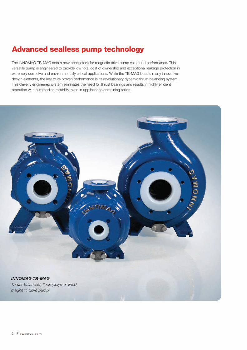
The INNOMAG TB-MAG sets a new benchmark for magnetic drive pump value and performance. This versatile pump is engineered to provide low total cost of ownership and exceptional leakage protection in extremely corrosive and environmentally critical applications. While the TB-MAG boasts many innovative design elements, the key to its proven performance is its revolutionary dynamic thrust balancing system. This cleverly engineered system eliminates the need for thrust bearings and results in highly efficient operation with outstanding reliability, even in applications containing solids.
INNOMAG TB-MAG Thrust-balanced, fluoropolymer-lined, magnetic drive pump
Advanced sealless pump technology
INNOMAG TB-MAG 3
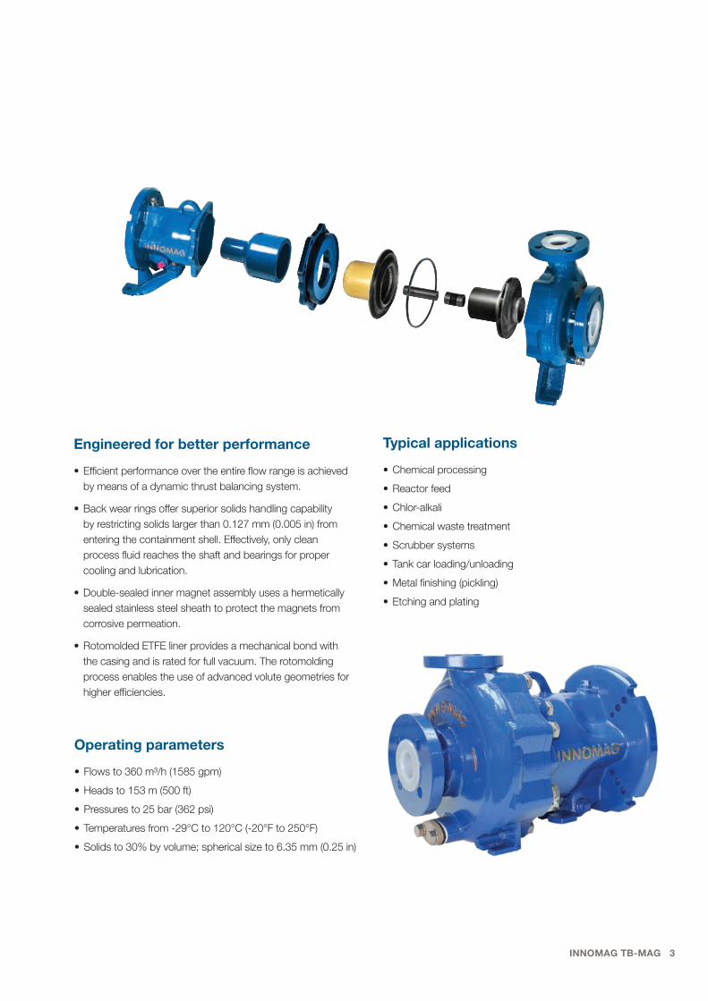
Engineered for better performance
• Efficient performance over the entire flow range is achieved by means of a dynamic thrust balancing system.
• Back wear rings offer superior solids handling capability by restricting solids larger than 0.127 mm (0.005 in) from entering the containment shell. Effectively, only clean process fluid reaches the shaft and bearings for proper cooling and lubrication.
• Double-sealed inner magnet assembly uses a hermetically sealed stainless steel sheath to protect the magnets from corrosive permeation.
• Rotomolded ETFE liner provides a mechanical bond with the casing and is rated for full vacuum. The rotomolding process enables the use of advanced volute geometries for higher efficiencies.
Typical applications
• Chemical processing
• Reactor feed
• Chlor-alkali
• Chemical waste treatment
• Scrubber systems
• Tank car loading/unloading
• Metal finishing (pickling)
• Etching and plating
Operating parameters
• Flows to 360 m3/h (1585 gpm)
• Heads to 153 m (500 ft)
• Pressures to 25 bar (362 psi)
• Temperatures from -29°C to 120°C (-20°F to 250°F)
• Solids to 30% by volume; spherical size to 6.35 mm (0.25 in)
4 Flowserve.com
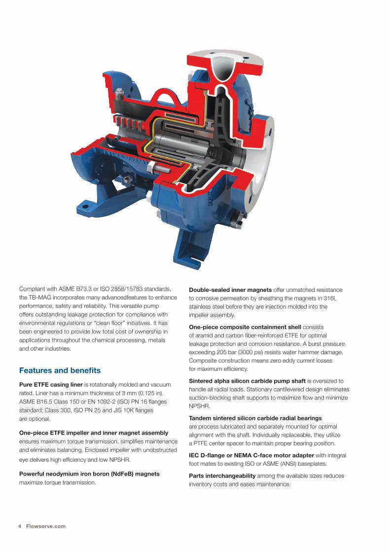
Compliant with ASME B73.3 or ISO 2858/15783 standards, the TB-MAG incorporates many advancedfeatures to enhance performance, safety and reliability. This versatile pump offers outstanding leakage protection for compliance with environmental regulations or “clean floor” initiatives. It has been engineered to provide low total cost of ownership in applications throughout the chemical processing, metals and other industries.
Features and benefits
Pure ETFE casing liner is rotationally molded and vacuum rated. Liner has a minimum thickness of 3 mm (0.125 in). ASME B16.5 Class 150 or EN 1092-2 (ISO) PN 16 flanges standard; Class 300, ISO PN 25 and JIS 10K flanges are optional.
One-piece ETFE impeller and inner magnet assembly ensures maximum torque transmission, simplifies maintenance and eliminates balancing. Enclosed impeller with unobstructed
eye delivers high efficiency and low NPSHR.
Powerful neodymium iron boron (NdFeB) magnets maximize torque transmission.
Double-sealed inner magnets offer unmatched resistance to corrosive permeation by sheathing the magnets in 316L stainless steel before they are injection molded into the impeller assembly.
One-piece composite containment shell consists of aramid and carbon fiber-reinforced ETFE for optimal leakage protection and corrosion resistance. A burst pressure exceeding 205 bar (3000 psi) resists water hammer damage. Composite construction means zero eddy current losses for maximum efficiency.
Sintered alpha silicon carbide pump shaft is oversized to handle all radial loads. Stationary cantilevered design eliminates suction-blocking shaft supports to maximize flow and minimize NPSHR.
Tandem sintered silicon carbide radial bearings are process lubricated and separately mounted for optimal alignment with the shaft. Individually replaceable, they utilize a PTFE center spacer to maintain proper bearing position.
IEC D-flange or NEMA C-face motor adapter with integral foot mates to existing ISO or ASME (ANSI) baseplates.
Parts interchangeability among the available sizes reduces inventory costs and eases maintenance.
INNOMAG TB-MAG 5
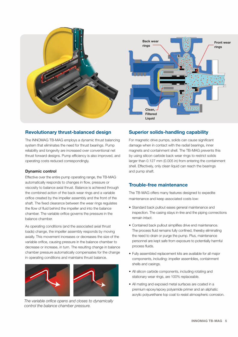
Revolutionary thrust-balanced design
The INNOMAG TB-MAG employs a dynamic thrust balancing system that eliminates the need for thrust bearings. Pump reliability and longevity are increased over conventional net thrust forward designs. Pump efficiency is also improved, and operating costs reduced correspondingly.
Dynamic controlEffective over the entire pump operating range, the TB-MAG automatically responds to changes in flow, pressure or viscosity to balance axial thrust. Balance is achieved through the combined action of the back wear rings and a variable orifice created by the impeller assembly and the front of the shaft. The fixed clearance between the wear rings regulates the flow of fluid behind the impeller and into the balance chamber. The variable orifice governs the pressure in the balance chamber.
As operating conditions (and the associated axial thrust loads) change, the impeller assembly responds by moving axially. This movement increases or decreases the size of the variable orifice, causing pressure in the balance chamber to decrease or increase, in turn. The resulting change in balance chamber pressure automatically compensates for the change in operating conditions and maintains thrust balance.
The variable orifice opens and closes to dynamically control the balance chamber pressure.
Back wear rings
Clean, Filtered Liquid
Front wear rings
Superior solids-handling capability
For magnetic drive pumps, solids can cause significant damage when in contact with the radial bearings, inner magnets and containment shell. The TB-MAG prevents this by using silicon carbide back wear rings to restrict solids larger than 0.127 mm (0.005 in) from entering the containment shell. Effectively, only clean liquid can reach the bearings and pump shaft.
Trouble-free maintenance
The TB-MAG offers many features designed to expedite
maintenance and keep associated costs low:
• Standard back pullout eases general maintenance and inspection. The casing stays in-line and the piping connections remain intact.
• Contained back pullout simplifies drive end maintenance. The process fluid remains fully confined, thereby eliminating the need to drain or purge the pump. Plus, maintenance personnel are kept safe from exposure to potentially harmful process fluids.
• Fully assembled replacement kits are available for all major components, including: impeller assemblies, containment shells and casings.
• All silicon carbide components, including rotating and stationary wear rings, are 100% replaceable.
• All mating and exposed metal surfaces are coated in a premium epoxy/epoxy polyamide primer and an aliphatic acrylic polyurethane top coat to resist atmospheric corrosion.
6 Flowserve.com
Standards compliance
The TB-MAG is CE marked and compliant with applicable directives such as ATEX.
Materials of construction
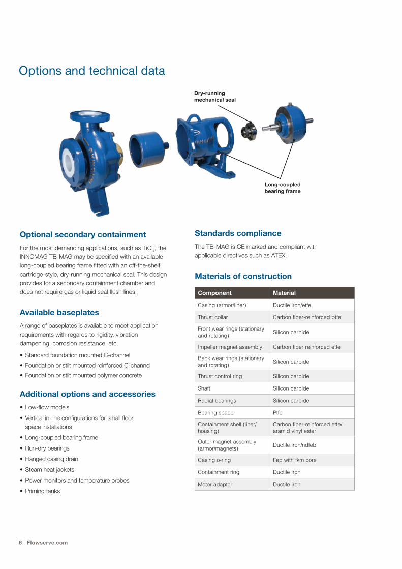
Optional secondary containment
For the most demanding applications, such as TiCl4, the INNOMAG TB-MAG may be specified with an available long-coupled bearing frame fitted with an off-the-shelf, cartridge-style, dry-running mechanical seal. This design provides for a secondary containment chamber and does not require gas or liquid seal flush lines.
Available baseplates
A range of baseplates is available to meet application requirements with regards to rigidity, vibration dampening, corrosion resistance, etc.
• Standard foundation mounted C-channel
• Foundation or stilt mounted reinforced C-channel
• Foundation or stilt mounted polymer concrete
Additional options and accessories
• Low-flow models
• Vertical in-line configurations for small floor space installations
• Long-coupled bearing frame
• Run-dry bearings
• Flanged casing drain
• Steam heat jackets
• Power monitors and temperature probes
• Priming tanks
Component Material
Casing (armor/liner) Ductile iron/etfe
Thrust collar Carbon fiber-reinforced ptfe
Front wear rings (stationary and rotating) Silicon carbide
Impeller magnet assembly Carbon fiber reinforced etfe
Back wear rings (stationary and rotating) Silicon carbide
Thrust control ring Silicon carbide
Shaft Silicon carbide
Radial bearings Silicon carbide
Bearing spacer Ptfe
Containment shell (liner/housing)
Carbon fiber-reinforced etfe/aramid vinyl ester
Outer magnet assembly (armor/magnets) Ductile iron/ndfeb
Casing o-ring Fep with fkm core
Containment ring Ductile iron
Motor adapter Ductile iron
Options and technical data
Dry-running mechanical seal
Long-coupled bearing frame

INNOMAG TB-MAG 7
A1-1.5x1x6, A3-3x1.5x6, A4-3x2x6
B1-1.5x1x8, B3/B5-3x2x6, B4-3x1.5x8, B6-4x3x6
C1-3x2x8, C2-4x3x8, C3-2x1x10, C4-3x1.5x10, C5-3x2x10, C6-4x3x10, C7-4x3x10H, C8-6x4x10H, C9-6x4x8
G2
F1
F4
E3
E1
ftm ftm
ftm ftm
gpm
m3/ h
gpm
m3/ h
gpm
m3/ h
gpm
m3/ h
TDH
- 60
Hz
TDH
- 50
Hz
Flow Rate - 60 Hz
TDH
- 60
Hz
Flow Rate - 60 Hz
G2
F4F1
E3
E1
CL
W1BL
V1AL
CL
W1BL
V1AL
C8C7
C9
C6
C5
C4
C3
C2
C1
B1
B6
B4
A3/4B3/5
A1
0
20
40
60
80
100
120
140
0 200 400 600 800 1000 1200 14000
5
10
15
20
25
30
35
40
ftm
TDH
- 50
Hz
0
20
40
60
80
100
0
5
10
15
20
25
30
0
20
40
60
80
100
120
140
0
5
10
15
20
25
30
35
40
ftm
0
20
40
60
80
100
0
5
10
15
20
25
30
0 50 100 150 200 250 300 350
C9
C6
C5C4C3
C2
C1B4B1
B6B3/B5
A3/A4A1
0
100
200
300
400
500
600
0 200 400 600 800 1000 1200 14000
20
40
60
80
100
120
140
160
180 ftm
0
100
200
300
400
0
20
40
60
80
100
120
0
100
200
300
400
500
600
0
20
40
60
80
100
120
140
160
180ftm
0
100
200
300
400
0
20
40
60
80
100
120
0 50 100 150 200 250 300 350
gpm
m3/ h
Flow Rate - 50 Hz
0 200 400 600 800 1000 1200
0 50 100 150 200 250
gpm
m3/ h
Flow Rate - 50 Hz
TDH
- 60
Hz
TDH
- 50
Hz
Flow Rate - 60 Hz
TDH
- 60
Hz
Flow Rate - 60 Hz
TDH
- 50
Hz
Flow Rate - 50 Hz Flow Rate - 50 Hz
TDH
- 60
Hz
TDH
- 50
Hz
Flow Rate - 60 Hz
TDH
- 60
Hz
Flow Rate - 60 Hz
TDH
- 50
Hz
Flow Rate - 50 Hz Flow Rate - 50 Hz
0 200 400 600 800 1000 1200
0 50 100 150 200 250
0
10 20 30 40 500
50 100 150 200
m ft
gpm
m3/ h
0
13
25
38
50
63
75
0
50
100
150
200
250m ft
0
13
25
38
50
63
76
89
102
0
50
100
150
200
250
300
350
ftm
0
10
20
30
40
50
60
0
5
2.5
7.5
12.5
10
15
17.5ftm
0
10
20
30
40
50
60
70
80
0
5
2.5
7.5
12.5
10
15
17.5
20
22.5
25
0 100 200 300 400 500 600 700
0 20 60 8040 100 120 140 160
gpm
m3/ h
0 100 200 300 400 500 600 700
0 20 60 8040 100 120 140 160
800
180 200
gpm
m3/ h
0 50 100 150 200 250 300
0 10 30 4020 50 60 70
gpm
m3/ h
0 50 100 150 200 250 300 350 400
0 10 30 4020 50 60 70 80 90
0
5 10 15 20 250
20 40 60 80 100
TB-MAG Hydraulic Curves
TB-MAG Special Pumps
TB-MAG ISO/JIS
2 pole 4 pole
2 pole 4 pole
2 pole 4 pole
gpm
m3/ h
0
5 10 15 200
20 40 60 80gpm
m3/ h
0
10 20 30 400
50 100 150
G2
F1
F4
E3
E1
ftm ftm
ftm ftm
gpm
m3/ h
gpm
m3/ h
gpm
m3/ h
gpm
m3/ h
TDH
- 60
Hz
TDH
- 50
Hz
Flow Rate - 60 Hz
TDH
- 60
Hz
Flow Rate - 60 Hz
G2
F4F1
E3
E1
CL
W1BL
V1AL
CL
W1BL
V1AL
C8C7
C9
C6
C5
C4
C3
C2
C1
B1
B6
B4
A3/4B3/5
A1
0
20
40
60
80
100
120
140
0 200 400 600 800 1000 1200 14000
5
10
15
20
25
30
35
40
ftm
TDH
- 50
Hz
0
20
40
60
80
100
0
5
10
15
20
25
30
0
20
40
60
80
100
120
140
0
5
10
15
20
25
30
35
40
ftm
0
20
40
60
80
100
0
5
10
15
20
25
30
0 50 100 150 200 250 300 350
C9
C6
C5C4C3
C2
C1B4B1
B6B3/B5
A3/A4A1
0
100
200
300
400
500
600
0 200 400 600 800 1000 1200 14000
20
40
60
80
100
120
140
160
180 ftm
0
100
200
300
400
0
20
40
60
80
100
120
0
100
200
300
400
500
600
0
20
40
60
80
100
120
140
160
180ftm
0
100
200
300
400
0
20
40
60
80
100
120
0 50 100 150 200 250 300 350
gpm
m3/ h
Flow Rate - 50 Hz
0 200 400 600 800 1000 1200
0 50 100 150 200 250
gpm
m3/ h
Flow Rate - 50 Hz
TDH
- 60
Hz
TDH
- 50
Hz
Flow Rate - 60 Hz
TDH
- 60
Hz
Flow Rate - 60 Hz
TDH
- 50
Hz
Flow Rate - 50 Hz Flow Rate - 50 Hz
TDH
- 60
Hz
TDH
- 50
Hz
Flow Rate - 60 Hz
TDH
- 60
Hz
Flow Rate - 60 Hz
TDH
- 50
HzFlow Rate - 50 Hz Flow Rate - 50 Hz
0 200 400 600 800 1000 1200
0 50 100 150 200 250
0
10 20 30 40 500
50 100 150 200
m ft
gpm
m3/ h
0
13
25
38
50
63
75
0
50
100
150
200
250m ft
0
13
25
38
50
63
76
89
102
0
50
100
150
200
250
300
350
ftm
0
10
20
30
40
50
60
0
5
2.5
7.5
12.5
10
15
17.5ftm
0
10
20
30
40
50
60
70
80
0
5
2.5
7.5
12.5
10
15
17.5
20
22.5
25
0 100 200 300 400 500 600 700
0 20 60 8040 100 120 140 160
gpm
m3/ h
0 100 200 300 400 500 600 700
0 20 60 8040 100 120 140 160
800
180 200
gpm
m3/ h
0 50 100 150 200 250 300
0 10 30 4020 50 60 70
gpm
m3/ h
0 50 100 150 200 250 300 350 400
0 10 30 4020 50 60 70 80 90
0
5 10 15 20 250
20 40 60 80 100
TB-MAG Hydraulic Curves
TB-MAG Special Pumps
TB-MAG ISO/JIS
2 pole 4 pole
2 pole 4 pole
2 pole 4 pole
gpm
m3/ h
0
5 10 15 200
20 40 60 80gpm
m3/ h
0
10 20 30 400
50 100 150
G2
F1
F4
E3
E1
ftm ftm
ftm ftm
gpm
m3/ h
gpm
m3/ h
gpm
m3/ h
gpm
m3/ h
TDH
- 60
Hz
TDH
- 50
Hz
Flow Rate - 60 Hz
TDH
- 60
Hz
Flow Rate - 60 Hz
G2
F4F1
E3
E1
CL
W1BL
V1AL
CL
W1BL
V1AL
C8C7
C9
C6
C5
C4
C3
C2
C1
B1
B6
B4
A3/4B3/5
A1
0
20
40
60
80
100
120
140
0 200 400 600 800 1000 1200 14000
5
10
15
20
25
30
35
40
ftm
TDH
- 50
Hz
0
20
40
60
80
100
0
5
10
15
20
25
30
0
20
40
60
80
100
120
140
0
5
10
15
20
25
30
35
40
ftm
0
20
40
60
80
100
0
5
10
15
20
25
30
0 50 100 150 200 250 300 350
C9
C6
C5C4C3
C2
C1B4B1
B6B3/B5
A3/A4A1
0
100
200
300
400
500
600
0 200 400 600 800 1000 1200 14000
20
40
60
80
100
120
140
160
180 ftm
0
100
200
300
400
0
20
40
60
80
100
120
0
100
200
300
400
500
600
0
20
40
60
80
100
120
140
160
180ftm
0
100
200
300
400
0
20
40
60
80
100
120
0 50 100 150 200 250 300 350
gpm
m3/ h
Flow Rate - 50 Hz
0 200 400 600 800 1000 1200
0 50 100 150 200 250
gpm
m3/ h
Flow Rate - 50 Hz
TDH
- 60
Hz
TDH
- 50
Hz
Flow Rate - 60 Hz
TDH
- 60
Hz
Flow Rate - 60 Hz
TDH
- 50
Hz
Flow Rate - 50 Hz Flow Rate - 50 Hz
TDH
- 60
Hz
TDH
- 50
Hz
Flow Rate - 60 Hz
TDH
- 60
Hz
Flow Rate - 60 Hz
TDH
- 50
Hz
Flow Rate - 50 Hz Flow Rate - 50 Hz
0 200 400 600 800 1000 1200
0 50 100 150 200 250
0
10 20 30 40 500
50 100 150 200
m ft
gpm
m3/ h
0
13
25
38
50
63
75
0
50
100
150
200
250m ft
0
13
25
38
50
63
76
89
102
0
50
100
150
200
250
300
350
ftm
0
10
20
30
40
50
60
0
5
2.5
7.5
12.5
10
15
17.5ftm
0
10
20
30
40
50
60
70
80
0
5
2.5
7.5
12.5
10
15
17.5
20
22.5
25
0 100 200 300 400 500 600 700
0 20 60 8040 100 120 140 160
gpm
m3/ h
0 100 200 300 400 500 600 700
0 20 60 8040 100 120 140 160
800
180 200
gpm
m3/ h
0 50 100 150 200 250 300
0 10 30 4020 50 60 70
gpm
m3/ h
0 50 100 150 200 250 300 350 400
0 10 30 4020 50 60 70 80 90
0
5 10 15 20 250
20 40 60 80 100
TB-MAG Hydraulic Curves
TB-MAG Special Pumps
TB-MAG ISO/JIS
2 pole 4 pole
2 pole 4 pole
2 pole 4 pole
gpm
m3/ h
0
5 10 15 200
20 40 60 80gpm
m3/ h
0
10 20 30 400
50 100 150
ASME Sizes
Specialty Sizes — Low Flow and Vertical
ISO Sizes
E0-50x32x125B, E1-50x32x160A, EL/M/N-50x32x160L/M/N, E2-50x32x160B, E3-65x50x160A, E4-65x40x160B
F1-50x32x200A, FL/M/N-50x32x200L/M/N, F2-50x32x200B, F3-65x40x200B, F4-65x40x200A, F5-80x50x160B
G1-80x50x200B, G2-100x65x200B, G3-50x32x250B, G4-65x40x250B, G5-80x50x250B, G6-100x65x250B, G7-125x100x250B, G8-150x125x250B, G9-125x80x200B,
AL-1.5x1x6x6LF, V1-2x1.5x6
BL-1.5x1x8LF, W1-2x1.5x8
CL-2x1x10LF
ASME Sizes Specialty Sizes ISO Sizes

flowserve.com
Flowserve Corporation5215 North O’Connor Blvd.Suite 2300Irving, Texas 75039-5421 USATelephone: +1 937 890 5839
PS-10-36d (E/A4) January 2019
Flowserve Corporation has established industry leadership in the design and manufacture of its products. When properly selected, this Flowserve product is designed to perform its intended function safely during its useful life. However, the purchaser or user of Flowserve products should be aware that Flowserve products might be used in numerous applications under a wide variety of industrial service conditions. Although Flowserve can provide general guidelines, it cannot provide specific data and warnings for all possible applications. The purchaser/user must therefore assume the ultimate responsibility for the proper sizing and selection, installation, operation, and maintenance of Flowserve products. The purchaser/user should read and understand the Installation Instructions included with the product, and train its employees and contractors in the safe use of Flowserve products in connection with the specific application.
While the information and specifications contained in this literature are believed to be accurate, they are supplied for informative purposes only and should not be considered certified or as a guarantee of satisfactory results by reliance thereon. Nothing contained herein is to be construed as a warranty or guarantee, express or implied, regarding any matter with respect to this product. Because Flowserve is continually improving and upgrading its product design, the specifications, dimensions and information contained herein are subject to change without notice. Should any question arise concerning these provisions, the purchaser/user should contact Flowserve Corporation at any one of its worldwide operations or offices.
©2019 Flowserve Corporation. All rights reserved. This document contains registered and unregistered trademarks of Flowserve Corporation. Other company, product, or service names may be trademarks or service marks of their respective companies.


