
1/10
Increased efficiency and reliability through an electro-mechanical
differential system providing variable speed to pumps and compressors
Maximilian Hehenberger1,*
1SET Sustainable Energy Technologies GmbH, Sterneckstraße 19, 9020 Klagenfurt, Austria
*Correspondence: Email: [email protected], Tel: +43 508988 288
Keywords: electro-mechanical differential system, drive train, E-motor, variable speed
concept, low voltage frequency converter
© [Maximilian Hehenberger, 2016]. The definitive version of this article is published in the 13TH European Fluid Machinery Congress, Institution of Mechanical Engineers, 2016
Abstract
The objective of this paper is to assess an electro-mechanical differential system (EMDS) system
providing variable speed to a driven machine (e.g. compressor, blower, pump, etc.) in terms of
applicability and energy efficiency. At the beginning of 2015 the European Union released a
new standard, the EN 50598 series, leading to increased demand for variable speed drives.
Beyond other drive train technologies, the EMDS is one possible solution for meeting the
standard’s requirements. In this connection, efficiency and the resulting life cycle costs are
essential to ensure compliance. The assessment of the EMDS reveals that this drive train
technology is a compatible solution to meet future challenges.
Abbreviations
ASM asynchronous machine
EMDS electro-mechanical differential system
HDC hydro-dynamic coupling
HDVSD hydro-dynamic variable speed drive
IGBT insulated-gate bipolar transistor
LV low voltage
MV medium voltage
VFD variable frequency drive

2/10
1. Introduction
Today industry worldwide is subject to major changes as a result of global warming, fast
changing commercial conditions, and air pollution. The policy is to ensure the continued
availability of natural resources and to prevent a collapse of the environmental system.
In Germany, for example, industry uses 30% of all electricity in the country. Of that figure, 70%
is consumed by electrically driven machines. The energy costs of these machines account for at
least 80% of the total life cycle costs [1]. In Strategy Europe 2030, the European Union (EU)
has defined the goals for energy management until 2030. The agreement specifies a reduction
in CO2 emissions of 40% and an increase in both renewable energy and energy efficiency of
27% [2].
In 2011 the EU issued regulations stating minimum efficiency requirements for electric motors.
At the beginning of 2015 a directive came into force requiring speed regulation in IE 3 motors
between 7.5 and 375 kW, as reflected in the EN 50598 series standard [3], [1]. Thus, there is
increasing pressure on industry to increase the efficiency of the whole drive train.
There is also a high demand for both cost effective and efficient drive train systems and the
policy to develop extensive, forward-looking legislation.
2. State of Drive Train Concepts
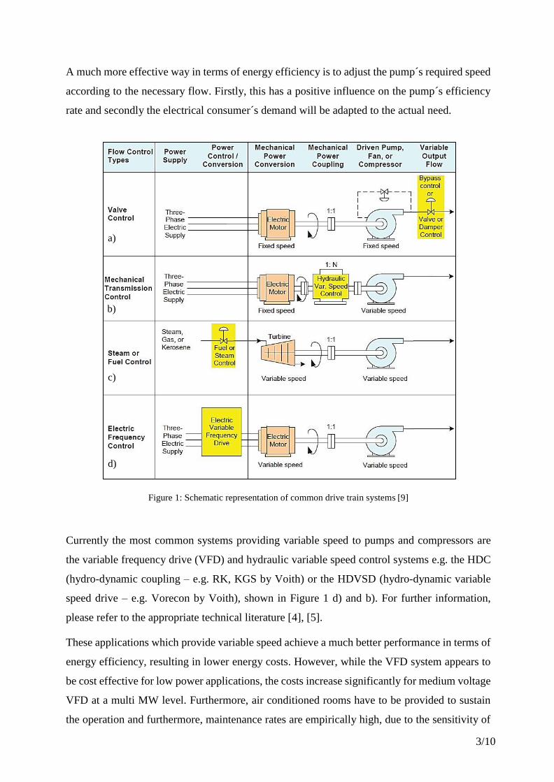
There are a couple of ways to provide speed from an electric machine to a driven machine, as
shown in Figure 1. The first and the easiest one is the direct drive, as shown in Figure 1 a). The
driven machine is connected directly to the main drive (motor), which is directly connected to
the grid – a variation of speed is not possible. To adjust the exact flow rate valves, dampers or
bypasses are used. Nowadays, the majority of new installed drive trains are direct driven
systems, due to initial cost driven motivations mostly. Although the apparent costs are low, the
energy costs are very high due to the main drive’s continuously high energy consumption. In
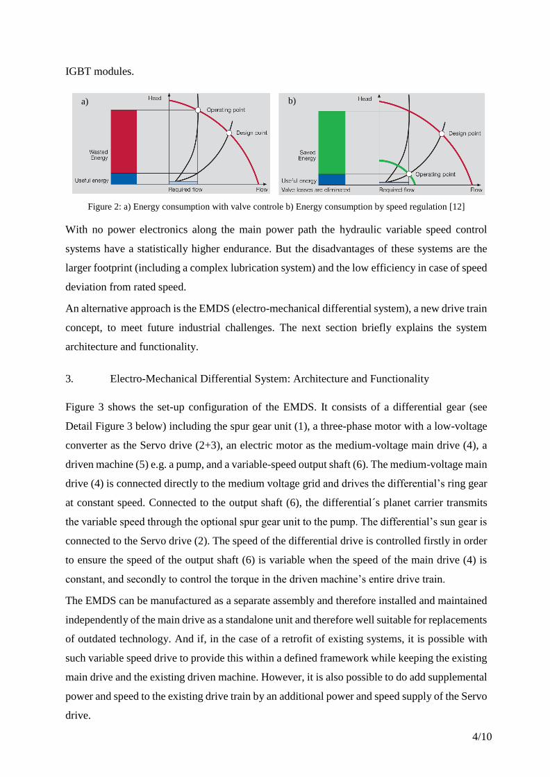
addition, the big disadvantage of this type of regulation is that the driven machine is not driven
in an optimum point of efficiency at partial load, see Figure 2.
In power plants, including smaller fossil plants e.g. turbines utilizing by-products from refinery
processes are often used to drive machines. The flow is adjusted by fuel or steam controls or
adjustable turbine blades changing the speed of the turbine, shown in Figure 1 c). However, as
efficiency increases with the size of the turbines, the investment may not be economically viable
for medium power applications.
3/10
A much more effective way in terms of energy efficiency is to adjust the pump´s required speed
according to the necessary flow. Firstly, this has a positive influence on the pump´s efficiency
rate and secondly the electrical consumer´s demand will be adapted to the actual need.
Figure 1: Schematic representation of common drive train systems [9]
Currently the most common systems providing variable speed to pumps and compressors are
the variable frequency drive (VFD) and hydraulic variable speed control systems e.g. the HDC
(hydro-dynamic coupling – e.g. RK, KGS by Voith) or the HDVSD (hydro-dynamic variable
speed drive – e.g. Vorecon by Voith), shown in Figure 1 d) and b). For further information,
please refer to the appropriate technical literature [4], [5].
These applications which provide variable speed achieve a much better performance in terms of
energy efficiency, resulting in lower energy costs. However, while the VFD system appears to
be cost effective for low power applications, the costs increase significantly for medium voltage
VFD at a multi MW level. Furthermore, air conditioned rooms have to be provided to sustain
the operation and furthermore, maintenance rates are empirically high, due to the sensitivity of
a)
b)
c)
d)
4/10
IGBT modules.
With no power electronics along the main power path the hydraulic variable speed control
systems have a statistically higher endurance. But the disadvantages of these systems are the
larger footprint (including a complex lubrication system) and the low efficiency in case of speed
deviation from rated speed.
An alternative approach is the EMDS (electro-mechanical differential system), a new drive train
concept, to meet future industrial challenges. The next section briefly explains the system
architecture and functionality.
3. Electro-Mechanical Differential System: Architecture and Functionality
Figure 3 shows the set-up configuration of the EMDS. It consists of a differential gear (see
Detail Figure 3 below) including the spur gear unit (1), a three-phase motor with a low-voltage
converter as the Servo drive (2+3), an electric motor as the medium-voltage main drive (4), a
driven machine (5) e.g. a pump, and a variable-speed output shaft (6). The medium-voltage main
drive (4) is connected directly to the medium voltage grid and drives the differential’s ring gear
at constant speed. Connected to the output shaft (6), the differential´s planet carrier transmits
the variable speed through the optional spur gear unit to the pump. The differential’s sun gear is
connected to the Servo drive (2). The speed of the differential drive is controlled firstly in order
to ensure the speed of the output shaft (6) is variable when the speed of the main drive (4) is
constant, and secondly to control the torque in the driven machine’s entire drive train.
The EMDS can be manufactured as a separate assembly and therefore installed and maintained
independently of the main drive as a standalone unit and therefore well suitable for replacements
of outdated technology. And if, in the case of a retrofit of existing systems, it is possible with
such variable speed drive to provide this within a defined framework while keeping the existing
main drive and the existing driven machine. However, it is also possible to do add supplemental
power and speed to the existing drive train by an additional power and speed supply of the Servo
drive.
Figure 2: a) Energy consumption with valve controle b) Energy consumption by speed regulation [12]
a) b)

5/10
Figure 3: EMDS system architecture [6]
The system is self-contained and performs all control and feedback tasks automatically. The
interface for controlling the system from outside can be maintained through a large variety of
existing types of interfaces. In general, the system components do comply with standard
components, widely used in the industry, which increases its reliability significantly.
4. Technical Background
The relation between the speeds in the differential stage of the EMDS is shown in the following
equation:
speedmotor = x * speeddriven machine shaft + y * speedServo drive
where the motor speed is constant, and factors x and y can be derived from the transmission
Ring Gear – connected main
drive – constant
speed
Planet Carrier – connected to driven machine
– variable output speed
Sun Shaft – connected to differential drive – adjustment of variable speed
Detail Figure 3: Differential stage (1) [6]

6/10
ratios of the pre-stage gear and the differential stage. The torque at the driven machine’s shaft
is determined by the delivery head and flow rate required. The ratio between the torque at the
driven machine shaft and that at the Servo drive is constant, enabling the torque in the drive train
to be controlled by the Servo drive. The torque equation for the Servo drive:
torqueServo drive = torquedriven machine shaft * y / x
where the factor y/x is a measure of the necessary design torque for the Servo drive.
The Servo drive’s power rating is essentially proportional to the product of the percentage the
driven machine speed deviates from its “basic speed” time’s shaft power. As a result, a wide
speed range basically requires the Servo drive to be dimensioned accordingly.
Figure 4 shows an example of the power ratios of a differential stage for a driven machine. To
work highly efficiently the Servo drive utilizes both speed directions and operates as a generator
and a motor depending on the set speed for the driven machine. This means that power is
supplied to the Servo drive in the motor range and withdrawn from the Servo drive in the
generator range to be restored in the grid. The sum of motor power and Servo drive power is
equal to the total power delivered to the driven machine’s shaft, leading to a reduction of the
main drive´s necessary power.
By using an (integrated) pre-stage gear, any speed required can be achieved for the driven
machine and thus the use of multi-pole drive motors can be avoided for stepping down speed.
Figure 4: Speed and power ratios for a differential stage [7]
5. Efficiency Comparison
Based on the fact that the losses from the differential stage are insignificantly low for the EMDS,
the efficiency limitations of the ASM (main drive), Servo drive and low-voltage frequency
converter are decisive. Past investigations and analysis have shown that approximately only 8

7/10
kW are lost through friction for a 2 MW differential stage [8]. Higher power losses are expected
for the frequency converter and its auxiliaries. But these influences are low, due to the fact that
the power required for controlling the system is linked to the driven speed range. Only a maximal
of approximately 20% of the power flows through the Servo path for a 100% driven machine’s
speed variability, leading to minimum losses of the whole system for the EMDS.
In comparison the VFD system shows much lower overall efficiency, due to the losses from the
frequency converter and auxiliary devices like harmonic filters, air-conditioning equipment,
step-up gearbox, transformer station etc. designed for rated driven machine´s power.
At rated power the HDC (hydro dynamic gear coupling e.g. RK by Voith) shows comparable
performance with the EMDS system, but when operating speed deviates from the design point,
the efficiency rates, due to hydraulic system losses, increase significantly. The same applies for
the hydro dynamic variable speed drive (HDVSD – Vorecon by Voith), although a higher overall
performance is achieved.
Figure 5 shows the calculated efficiency rates of the most common drive train concepts for a
speed range from 50% to 100% n/nmax.
Figure 5: Calculated efficiency rates of various variable speed drive train concepts [5], [8], [9], [14], [15]
To underline the calculated outcomes Sulzer Pumpen (Deutschland) GmbH did investigations
on the EMDS on their in-house test facilities. The pure output tests of Sulzer Pumpen
(Deutschland) GmbH in Bruchsal, Germany pointed out that the EMDS shows excellent
efficiency results in operation:” The measured results confirm the project specifications without
exception. If the differential gearbox, including its auxiliary systems and converter, is
considered alone, the high efficiency specifications have been confirmed. Even in the partial
EMDS
VFD
HDVSD HDC

8/10
load ranges, the gearbox with servo motor and low voltage frequency converter achieves an
overall efficiency of >95 %. If the whole drive train is also taken into account, i.e. including the
main motor, the measured efficiency of the system ranges between 92.7 % and 94.1 %. “[10]
6. Energy Costs
For more and more operators in different industry sectors the energy consumption of their
machines becoming increasingly important. Fact is, that the energy costs have a major influence
on the LCCs (life cycle costs), especially if driven machines e.g. pumps run more than 2.000
hours a year [12]. “In two thirds of pumps and pump systems currently installed, it is possible
to save up to 60% energy by switching to pumps with high-efficiency motors and variable speed
drives” [13]. By comparing this statement with Figure 6, it becomes obvious that the initial costs
have a minor impact on a pump´s life time. A typical ROI (return on investment) for variable
speed drives compared to a direct drive system, depending very much on the required system
power, efficiency rates and partial load points, is between one and three years. And the need of
variable speed systems is growing.
One example is the increasing amount of installed alternative energy sources as e.g. wind
turbines or solar plants, forces power plant operators to become more flexible in their energy
productions to balance inconsistent green energy supply [16].
Figure 6: Influence of energy costs on LCC for a medium-sized industrial pump [12]
Table 1 illustrates the estimated savings by using a EMDS in comparison of alternative variable
speed drive trains for a boiler feed pump, a typical industrial application. It clearly explains that
each of the drives show high efficiency rates at its design point (100% n/nmax). By a deviation
of the rated operating point a big difference of efficiency rates between the EMDS and VFD or
hydrodynamic solutions is observed. The highest amount in yearly energy costs is determined
between the EMDS and the HDC, results in a current value of 382.549 € per year.

9/10
Table 1: Energy consumption example of common variable speed drives [5], [8], [9], [14], [15], [17]
7. Conclusion
The industry demands powerful systems in the future, and at the same time these systems should
become more efficient. Common systems like the VFD or hydraulic variable speed control
Operating Points (n/nmax) Design 100% Partial Load 75%
Operating time 4300 hours/a 4300 hours/a
Boiler feed pump power consumption 9.200 kW 3.810 kW
Boiler feed pump operating speed 6.200 rpm 4.630 rpm
Drive with VFD
Motor efficiency 97,3% 96,1%
VFD efficiency 98,0% 96,7%
Isolation transformer efficiency 99,0% 98,9%
Harmonic filter efficiency 99,0% 98,8%
Gearbox efficiency 98,5% 98,0%
Air condition equipment efficiency (MV-FC) 99,6% 99,4%
Overall efficiency 91,7% 88,5%
Energy consumption 43.140.676 kWh/a 18.511.864 kWh/a
Drive with HDVSD
Motor efficiency 97,5% 96,2%
HDVSD efficiency 95,0% 87,6%
Overall efficiency 92,6% 84,3%
Energy consumption 42.721.382 kWh/a 19.434.163 kWh/a
Drive with HDC
Motor efficiency 97,5% 96,2%
HDC efficiency 97,0% 87,6%
Overall efficiency 94,3% 71,0%
Energy consumption 41.951.219 kWh/a 23.074.648 kWh/a
Drive with EMDS
Motor efficiency 97,5% 96,2%
EMDS efficiency incl. LW-FC and Servo Drive 97,0% 96,5%
Overall efficiency 94,4% 92,8%
Energy consumption 41.906.780 kWh/a 17.654.094 kWh/a
Comparison
Energy Costs 0.07 €/kWh 0.07 €/kWh
Energy Savings
EMDS - VFD 1.189.457 kWh/a 857.770 kWh/a
EMDS - HDVSD 770.163 kWh/a 1.780.069 kWh/a
EMDS - HDC 44.439 kWh/a 5.420.554 kWh/a
Savings per year
EMDS - VFD 143.304 €/a
EMDS - HDVSD 178.516 €/a
EMDS - HDC 382.549 €/a
*estimated efficiency rates – all data without guarantee

10/10
systems meet the requirements unsatisfactory with respect to energy costs. The EMDS is a drive
train concept which shows high potential for variable speed drives in industrial applications.
The directly grid connected main drive and the small electronic parts for speed and torque
control enable both investment costs and losses to be reduced to a minimum. This results in a
highly efficient variable speed drive system. The minimum effort for power electronics for
controlling the drive, the small design of the Servo drive and a simple gearbox design guarantee
the highest possible reliability. Long-term operation will prove, if this approach does satisfy the
industry’s high standards and needs.
Reference list [1] Siemens Ag., "Energieeffizienz in Bewegung," Dispostelle 21511, Nürnberg, 2014.
[2] D. Bundestag, "Position der Bundesregierung zu den Vorschlägen der Europäischen Kommission zu den europäischen
Klima- und Energiezielen 2030," H. Heenemann GmbH & Co. ISSN 0722-8333, 12103 Berlin, 2014.
[3] D. I. f. Normung, "Ecodesign for power drive systems, motor starters, power electronics & their driven applications - Part
2: Energy efficiency indicators for power drive systems and motor starters; German version prEN 50598-2:2013," Beuth
Verlag GmbH, 10787 Berlin, 2013.
[4] J. Jenk, "Voltage Frequency Converter Basics," in Simplified Design of Voltage/Frequency Converters, Woburn,
Butterworth-Heinemann, 1997, p. 224. [5] Voith Turbo GmbH & Co. KG, "www.voith.com," 2014. [Online]. Available:
http://voith.com/en/1614_e_cr394_en_hydrodynamic- fluid-couplings_principles-features-benefits.pdf. [Accessed 19.02.
2015].
[6] SET GmbH, "www.set-solutions.net," 07.11.2014. [Online]. Available: http://www.set-
solutions.net/Industry.html. [Accessed 19.02.2015].
[7] SET GmbH, Product-Portfolio_DSgear-set, Klagenfurt, 11.12.2014.
[8] SET GmbH, Test bench Results_DN_181, Klagenfurt, 2014.
[9] TMEIC Corporation, "Selecting variable Speed Drives for Flow Control," 03 10 2011. [Online]. Available:
http://www.tmeic.com/Repository/Brochures/Selecting_VSDs_for_Flow_Control_Brochure-2011_low-
res_1314113714.pdf. [Accessed 03 10 2014].
[10] VDMA, Pumps and Compressors for the World Market with Compressed Air and Vacuum Technology 2016, “Highly
efficient speed regulation for centrifugal pumps”, Klaus Löffler, Dirk Küllmey [e-magazine]. Available: http://www.3d-
zeitschrift.de/p/6g7IlykacpMSx/Pumps_and_Compressorsfor_the_World_Market_2016.html?page=1. [Accessed
09.05.2016]
[11] Heggeman, Marc et al. "Variable speed pumps- Protecting the environment and reducing costs." Sulzer Technical
Review. 1/2009: 16-17. [12] Hydraulic Institute, “Pump Life Cycle Costs: A Guide to LCC Analysis for Pumping Systems”, 9 Sylvan Way
Parsippany, NJ 07054, DOE/GO-102001-1190, January 2001 [online]. Available:
https://www1.eere.energy.gov/manufacturing/tech_assistance/pdfs/pumplcc_1001.pdf [Accessed 08.05.2016].
[13] Grundfos, “The surprising truth about pumps”, [online]. Available: http://energy.grundfos.com/en/facts-on-pumps-
energy/the-surprising-truth-about-pumps [Accessed 10.05.2016].
[14] Voith Turbo GmbH & Co. KG, “Advanced Speed Control for pumps and Compressors – Vorecon with Dual Torque
Converter” [online]. Available: http://resource.voith.com/vt/publications/downloads/2073_e_cr442_en_voith-vorecon-
with-dual-torque-converter.pdf [Accessed 10.04.2016].
[15] Dipl.Ing. Bernd Harnisch, “Variable Speed Drives in the new Power Station Technology”, page 4., Voith Turbo GmbH
& Co. KG [online] Available: http://www.voith.com/en/255_e_cr576e.pdf [Accessed 4.05.2016].
[16] Univ. Prof. Dr. Dipl. Ing. Reinhard Haas, Energy Economics Group, TU Wien (AT), “Die Auswirkungen der
Energiewende auf die Strommärkte und die Rentabilität von konventionellen Kraftwerken“, discussion paper, Wien
2012
[17] Siemens, „What is drive system efficiency and why it is important? “[online]. Available: https://www.industry.usa.siemens.
com/drives/us/en/Integrated-Drive-Systems/document-library/Documents/DS_DriveSystemEfficiency-Application.pdf
[Accessed 11.05.2016].


