
1
Improved Differential Relay for Protection
of Three Phase Delta-Wye Transformer
1. Moazzam Ali 2015-EE-403
2. Waleed Tariq 2015-EE-406
3. Haider Ali 2015-EE-431
4. Talha Khan 2015-EE-447
Supervisor
Engr. Zain Shabbir
_______________________
Co-Supervisor
Dr. Aashir Waleed
_______________________

2
Department of Electrical Engineering
University of Engineering & Technology Lahore (Faisalabad Campus)
“Improved Differential Relay for protection of three phase delta-wye
transformer”
A report submitted in partial fulfilment of the
requirement for the degree of
B.Sc. Electrical Engineering
Internal Examiner External Examiner
Chairman
Department of Electrical Engineering
Department of Electrical Engineering
University of Engineering and Technology Lahore (FSD Campus)
April 2019

3
Declaration
We solemnly declare that this report is written by us and is not copied from any online or
printed material.
1. Moazzam Ali ___________________
2. Waleed Tariq ___________________
3. Haider Ali ___________________
4. Talha Khan ___________________
4
TABLE OF CONTENTS
TITLE PAGE 1
DECLARATION 3
LIST OF FIGURES 7
LIST OF TABLES 8
ABBREVIATIONS 9
SOFTWARES USED 10
ABSTRACT 11
1. INTRODUCTION 12
1.1 Problem statement 14
1.2 Literature overview 15
1.2.1 Background Study 15
1.2.2 Protection schemes 16
1.2.3 Transformer protection 17
1.3 Differential Protection 18
1.3.1 Ordinary differential protection 18
1.3.2 Percentage differential protection 19
1.4 Proposed differential relay 20
2. EXPERIMENTAL SETUP 21
2.1 Power Transformers 24
2.2 Arduino 25
2.3 Display 26
2.4 Current sensors 26
2.5 Buttons 27
2.5.1 Fault Buttons 27
2.5.2 Load Buttons 28
2.5.3 Reset Buttons 28
2.6 Wires 28

5
2.6.1 Jumper wires 28
2.6.2 3/29 wires 28
2.6.3 7/29 wires 29
2.7 Load 29
2.7.1 Holders 29
2.7.2 Incandescent bulbs 30
2.8 Connectors 30
2.8.1 Three phase connector 30
2.8.2 Connecting probes 30
2.8.3 Female connectors 31
2.9 Relays 31
2.10 Indicators 31
2.11 Acrylic sheet 32
2.12 Wooden sheets 32
2.13 Power supply 32
3. METHODOLOGY 33
3.1 Working principle 35
3.2 Internal fault behavior 36
3.3 External fault behavior 38
3.4 Simulations 39
3.5 Results 41
3.5.1 Internal fault analysis 41
3.5.2 Exernal fault analysis 42
4. HARDWARE IMPLEMENTATION 44
4.1 Hardware design 46
4.1.1 Designing on Coral Draw 46
4.1.2 Laser Engraving 46
4.1.3 Assembling of components 47
4.1.4 Making final connections 48
4.2 Fault Introduction 48
4.2.1 Incipient fault 48

6
4.2.2 Line to line fault 49
4.2.3 Tripple line fault 49
5. CONCLUSION AND FUTURE WORK 50
5.1 Conclusion 52
5.2 Features 52
5.3 Applications 53
5.4 Future work 54
REFRENCES 55
APPENDIX A 56
APPENDIX B 63

7
LIST OF FIGURES
Fig. 1.1: Transformer damaging ratio of last two decades
Fig. 1.2: Ordinary differential relay
Fig. 1.3: Percentage differential relay
Fig. 2.1: Ordinary small transformer
Fig. 2.2: Arduino MEGA328
Fig. 2.3: 16*4 LCD
Fig. 2.4: ACS712 current sensor
Fig. 2.5: Small push button
Fig. 2.13: Three phase connector
Fig. 2.10: Relay
Fig. 3.1: Block diagram
Fig. 3.2: Current loop during internal fault
Fig. 3.3: Current loop during external fault
Fig. 3.4: Simulation diagram
Fig. 4.4: Designed differential relay
Fig. 4.5: Current Waveform during internal fault
Fig. 4.6: Relay signal during internal fault
Fig. 4.7: Current Waveform during external fault
Fig. 4.8: Relay signal during external fault
Fig. 4.1: Coral Draw design
Fig. 4.2: Laser printed design
Fig. 4.3: Real time Trainer
Fig. 4.4: Trainer with input output Connections

8
LIST OF TABLES
Table 2.1 Transformer parameters
Table 2.2 Arduino datasheet
Table 2.3 ACS712 datasheet
Table 2.4 Load parameters
Table 3.1 Simulation parameters

9
ABBREVIATIONS
MI: Magnetizing Inrush
CT: Current Transformer
LL: Line to Line
TL: Triple Line
TLG: Triple Line to Ground
LCD: Liquid Crystal Display
PDR: Percentage Differential Relay
Np: turns on primary side of power transformer
Ns: turns on secondary side of power transformer
np: turns on primary side of current transformer
ns: turns on secondary side of current transformer

10
SOFTWARES USED
MATLAB/SIMULINK
CORAL DRAW
ARDUINO IDE

11
ABSTRACT
The proposed differential relay is a reliable, relatively low cost lab equipment, composed of power
transformer whose primary and secondary currents are measured through electrical transducers
connected in series with power transformer. Percentage differential scheme is applied to protect
transformer in case of internal fault. This relay has significant advantages as compared to conventional
differential relay. A Trainer is designed for performing the lab of power system protection. Proposed
algorithm will compute the primary and secondary currents and will calculate their difference. This
difference will be compared by fraction of input current. Designed relay will be able to trip on
occurrence of internal fault and will have ability to restrain while introducing external fault. Relay will
restrain mal-operation in case of starting inrush current. The proposed system will be simulated in
MATLAB-SIMULINK environment and will be designed on microcontroller arduino MGA328.

12
CHAPTER 1: INTRODUCTION
Problem Statement
Literature Overview
Differential Protection
Proposed Differential Relay

13
[This page is kept blank intentially ]

14
1.1 Problem Statement
Power transformer is the most important equipment to transfer power in power system. If power
transformer experiences a fault then, it is necessary to have transformer out of service until fault is
removed. The unplanned outage can cause a big damage. The cost to repair a damaged transformer is
very high (millions of dollars). That’s why protective relays are used to protect power transformer
from being damaged. It ease to fix a relay rather than to a transformer. So, Differential relay is used to
protect transformer from internal fault. In some cases it fails to operate or mal-operationdue to MI
currents, stationary over excitation of core, external faults in the presence of CT saturation, power
transformer ratio mismatch, operation due to high second harmonic component. In this scenario
percentage differential protection, harmonic-restrained differential protection is used, respectively.
Percentage differential protection is a developed idea of ordinary differential protection which had
made quite satisfactory solutions to the above mentioned problems. The requirements include
dependability (no missing operations), security (no mal-operation), and speed operation (short fault
clearing time).

15
1.2 Literature Overview
Power transformers are important and widely used equipment in power system. Due to their large size
and price, it is much difficult to replace them in case of any damage. Power system demands high
protection and reliability against abnormal conditions to avoid instability and disturbance. So
protection of this equipment has primary importance in protection system, transformer is protected
through different techniques.
1.2.1 Background Study
Power transformer is the most important equipment to transfer power in power system which may
subjected to internal fault, Magnetizing Inrush (MI), Current Transformer (CT) saturation and internal
fault, through fault current due to transient disturbances in the system [1]. Saturation of CT may yield
to mal-operation of relay. That’s why CT is the most accurate equipment in power system protection
and its ratio error must be lesser. Normally MI is evaluated through second harmonic component
variation more than 10% [2]. Such as harmonic restraint differential relay based on that due to MI
current second harmonic component is large, but second frequency component is decreased due to
advancement in core.
Turn-to-turn fault may leads to some serious damage in transformer windings and cause explosion
because of overheating of insulating liquid. Consequently, windings must be protected to avoid major
damages. Diagnosis of incipient faults at an early stage is the key of ensuring reliable electrical power
supply to consumers [3]. To detect incipient fault various methods are suggested as dissolved gas
analysis, due to variability in gas data, it is ineffective method. A study of breakdown of power
transformers, 70% of transformers are damaged permanently due to undetected short circuited faults
earlier [4-5]. Thus it is necessary at very early stages to identify the fault so one can make progressive
arrangements for counteractive measures and executed quickly [6]. Most of the times internal faults
are catastrophic and thus results in permanent internal damage. It is there for very essential to carefully
monitor their online behavior [7]. Losses in no load and increased load conditions have been studied
as well to experimently show inter-turn faults if the windings get shorted. However the effect of core
degradation can influence no-load losses [8]. Transformer protection method that use its terminal
behavior based on differential protection and studies for enlargement of transformer protection have
concentrated on discrimination between internal short circuit faults and inrush currents in transformers
[9].
16
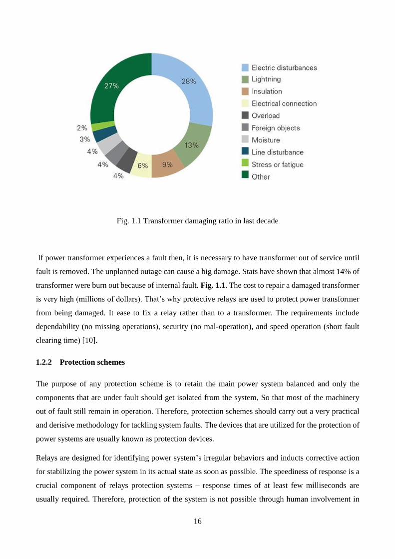
Fig. 1.1 Transformer damaging ratio in last decade
If power transformer experiences a fault then, it is necessary to have transformer out of service until
fault is removed. The unplanned outage can cause a big damage. Stats have shown that almost 14% of
transformer were burn out because of internal fault. Fig. 1.1. The cost to repair a damaged transformer
is very high (millions of dollars). That’s why protective relays are used to protect power transformer
from being damaged. It ease to fix a relay rather than to a transformer. The requirements include
dependability (no missing operations), security (no mal-operation), and speed operation (short fault
clearing time) [10].
1.2.2 Protection schemes
The purpose of any protection scheme is to retain the main power system balanced and only the
components that are under fault should get isolated from the system, So that most of the machinery
out of fault still remain in operation. Therefore, protection schemes should carry out a very practical
and derisive methodology for tackling system faults. The devices that are utilized for the protection of
power systems are usually known as protection devices.
Relays are designed for identifying power system’s irregular behaviors and inducts corrective action
for stabilizing the power system in its actual state as soon as possible. The speediness of response is a
crucial component of relays protection systems – response times of at least few milliseconds are
usually required. Therefore, protection of the system is not possible through human involvement in
17
this situatuons. The relay response time needed to be swift, automatic and must cause a minimum
amount of disturbance to the power system. Various Protection Schemes are:
Transmission Lines Protection
Rotating Machinery Protection
Bus Bar, Reactor Protection
Transformer Protection
Feeder Protection
The intrinsic characteristics of power transformers is a reason for introducing some exceptional
complications that are not existing in the protection of transmission lines, generators and motors. [11]
1.2.3 Transformer protection
Transformer faults – i.e short circuits – are a reason of internal electric faults, and the most frequent
one is phase-to-ground fault. And a bit less frequent one is turn-to-turn fault. The physical extent of a
transformer is different from a transmission line as it is bounded within a substation, and hence
differential relay scheme which is a quite appropriate method of protection present, can be utilized for
protection of transformers. Generally fuses, overcurrent relays, differential relays, and pressure relays,
are used for the protection of transformer and can be observed for incipient fault by winding
temperature measurements, and chemical exploration of the gas above the insulating oil. Out of these
the one to be used depends uon the following factors:
Transformer Size: Transformers rated 2500 kVA or less are commonly protected through fuses.
Transformers ranging from 2500 to 5000 kVA can also be protected by fuses, but prefered to be
protected through instantaneous and time-delay overcurrent relays. And for ratings between 5000
and 10,000 kVA, an induction disc overcurrent relay is attached with system in a differential
configuration. Above 10 MVA, a harmonic restraint, percentage differential relay is implemented.
Some other realys utlilized with such ratings of transformers are Pressure and temperature relays.
Location and Function: Only the size of transformer doesn’t decide which relay is to be suitably
utilized for the protection of system, One must consider the importance of the transformer within
the power network., A more sophisticated relays is to be utlilized in terms of design and
redundancy if transformer is an integral part of the power system. But if it is a simple step-down
transformer of a distribution station, a single differential relay and overcurrent backup would be
enough.

18
Voltage: In general, more advanced and costly protective devices are reuired to deal with higher
voltages, due to the irreversible destructive effect of a delayed fault clearing on the system
operation and as the transformer repairing is quite costly.
Connection and Design: When you shift from an autotransformer to two- or three-winding
transformers the protection schemes would be varied accordingly. Even the winding connection of
a three-phase transformer – whether delta or wye – will make the protection scheme chosen
differently. The presence of tertiary windings, type of grounding used, tap changers, or phase-
shifting windings must also be taken into account.
1.3 Differential Protection
Differential protection is a unit-type protection for a specified zone or piece of equipment. It can be
applied considering the difference of currents between the internal fault zone and to the zone with high
differential current (difference between input and output currents). However, even if there is no
internal fault the differential current can sometimes be seen significantly due to some certain
characteristics of current transformers (different saturation levels, nonlinearities) measuring the input
and output currents.
Differential protection is based on the fact that power at input side to the transformer under normal
condition is equal to power at output side [12].
The following are the classification of the differential protection relay:
Current Differential Relay
Voltage Differential Relay
Biased or Percentage Differential Relay
Voltage Balance Differential Relay
1.3.1 Ordinary differential protection
Conventional differential technique is based on difference of currents measured by primary and
secondary side CT. Matching of CT ratios is important parameter in this technique. Ratios of current
transformers used on primary and secondary side of power transformer are selected in such a way that
secondary side of both current transformers show same current. Difference of these currents flows
through differential relay.

19
In practical cases, exact CT ratios are not available commercially in order to fulfill our requirements.
So, a certain value of current always passes through relay due to unbalance CT ratios. Another major
problem in this technique is CT error. Current transformers does not measure actual value but have
some error in measurement which causes flow of current in differential relay. This error is minimum
at low current but increases as line current increases because this error is some percentage of primary
side current of CT. An ordinary differential relay is shown in Fig 1.2.
Fig. 1.2: Ordinary differential relay
At very large current this difference is significant and consequently results in mal operation of relay.
Starting inrush current is another problem in conventional differential technique. Power transformer
draws heavy starting current for magnetizing of core. This current is seen by only primary side
current transformer which creates major difference in measurement of both currents causes ultimate
false tripping of relay.
1.3.2 Percentage differential protection
Differential protection is used to protect transformer from internal fault. In some cases it fails to operate
or mal-operationdue to MI currents, stationary over excitation of core, external faults in the presence
of CT saturation, power transformer ratio mismatch, operation due to high second harmonic
component. In this scenario percentage differential protection, harmonic-restrained differential
protection is used, respectively. Percentage differential protection is a developed idea of ordinary
differential protection which had made quite satisfactory solutions to the above mentioned problems.

20
A restraining coil is used in a percentage differential relay for overcoming the fault occuring due to
external short circuit which causes the difference of currents. The percentage differential system
consists of a restraining coil attached in the pilot wire as shown in the Fig 1.3. and the current induced
in both the CTs flows through it. There is a operating coil attached between the midpoint of the
restraining coil.
Fig. 1.3: Percentage differential relay
The problems (MI currents, stationary over excitation of core, external faults in the presence of CT
saturation, power transformer ratio mismatch, operation due to high second harmonic component) are
considered in percentage differential technique to provide stability to power system. In this protection
scheme spill current is not compared to constant value but it varies as input current varies. Spill current
is compared with fraction of line current. As current increases, fractional value of current also
increases.
Starting inrush magnetizing current is although very high but it is controlled by percentage differential
relay. Because when input current increases specific percentage of line current also increases and relay
withstands input transient response of transformer. Similarly, Margin of CT error as well as CT
mismatch is also considered in this scheme.

21
1.4 Proposed Differential Relay
A restraining coil is used in a percentage differential relay for overcoming the fault occuring due to
external short circuit which causes the difference of currents. Our relay also based on current difference
principle. It measures the current on both sides of transformer with CT and take difference. Designed
differential relay will retain on external fault and will trip on occurrence of internal fault. High inrush
current results in mal-operation of conventional differential relays. Percentage differential relay is used
to solve this problem. Our relay compares percentage of line current with spill current. If spill current
is greater than 40% of line current, it will cause trip of relay. High inrush current will be allowed by
relay as spill current is less than percent in case of starting of transformer.

22
CHAPTER 2: EXPERIMENTAL SETUP
Power Transformer
Arduino
Display
Current Sensors
Buttons
Wires
Load
Connectors
Relays
Indicators
Acrylic Sheet
Wooden Sheet
Power Supply

23
[ This page is kept blank intentially ]

24
2.1 Power Transformers
We have used 3 single phase transformers and have configured them in three phase wye-delta
connections. The basic purpose of a Power Transformer is to transfer electrical energy through circuits
to either electrical or electronics components like generators or the distribution primary circuits. Such
transformers are basically used for stepping up and down the voltages in distribution systems. Power
transformer is the major equipment to transfer power in power system which may subjected to internal
fault, Magnetizing Inrush (MI), Current Transformer (CT) saturation and internal fault, through fault
current due to transient disturbances in the system.
Fig. 2.1: Ordinary small transformer
Trasformer parameters
Paramater Value
Power Rating 440VA
Operating Voltage 220V
Output Voltage 75V, 110V, 220V
Operating Frequency 50Hz
Maximum Current 2.02A
Table 2.1: Trasformer parameters

25
2.2 Arduino
We have used arduino in our project for interfacing the relays, current sensors and LCD with the
transformer and the main system. Arduino Uno is comprised of an ATmega328P processor chip built
in on a microcontroller board. It consist of 14 digital I/O pins (out of these 6 can be used as PWM
outputs) and 6 analog input pins. Moreover it has a 16 MHz quartz crystal, USB connection, power
jack, an ICSP header and reset button. It consists of most of the major components to support the
microcontroller.
Arduino Datasheet
Paramater Value
DC Current per I/O Pin 20 mA
Operating Voltage 5 V
Flash Memory 32 KB
SRAM 2 KB (ATmega328P)
EEPROM 1 KB (ATmega328P)
Clock Speed 16 MHz
Table 2.2: Arduino Datasheet
Fig. 2.2: Arduino MEGA328

26
2.3 Display
We have attached an 16x4 LCD (Liquid Crystal Display) to Display the required outputs and results
of the working system. LCD is an electronic module used as display screen and and have many
applications. LCD display with dimensions 16x4 is usually used in several electronic devices.
Consisting of seven and multi segments LEDs they display the required output on screen. They are
usually prefered beacause are easy to program, low cost, can dsilay animations and have no
unnecessary limitation of displaying different characters. A 16x4 LCD can display 16 characters per
line and there are 4 such lines.
Fig. 2.3: 16*4 LCD
2.4 Current Sensors
We have used six ACS712 current sensors for measuring the current using Hall Effect. Three sensors
on the primary side and three on the secondary followed by relays. The ACS712 Module consist of a
ACS712 IC to measure the current and uses Hall Effect principle for it. The name of this module is
due to the IC (ACS712) implanted in it, as it is basically using the IC for the work.. This module can
comute AC or DC current having range from +5A to -5A, +20A to -20A and +30A to -30A. The one
we have used in our project is of range +30A to -30A for the accurate operation of the system.
Depending upon the current flowing through the wire this modules outputs Analog voltage (0-5V);
making it quite easy for interfacing this module with any microcontroller.

27
Fig. 2.4: ACS712 current sensor
ACS 712 Datasheet
Paramater Value
Supply Voltage (VCC) 5V dc
Measurement Range -5 to +5 Amps
Voltage at 0A VCC/2 (nominally 2.5Vdc)
Scale Factor 185 mV per Amp
Chip ACS712ELC-05A
Table: 2.3: ACS 712 Datasheet
2.5 Buttons
Different buttons are used in project according to our requirement such as push buttons, On-Off buttons
as well as small push buttons. Detail of these buttons and area of use is given below.
2.5.1 Fault Buttons
Fig. 2.5: Small push button
To generate the faults we have placed three push
buttons (Red, Green, Yellow) on our trainer through
which we test the functionality of our relays. Red
button is for the incipient fault, Blue for line to line
and Yellow for triple line. These buttons are
normally open in normal state and their contacts
become short circuited on pushing buttons.

28
2.5.2 Load Buttons
We have used a switch board with six buttons on it and have connected the load with it. Through these
buttons we control the load on the system and examine system operation.
2.5.3 Reset Buttons
A reset button is attached as well to bring our system back to normal after testing it on different faults.
This button is also open in normal state and gives high value to reset pin of arduino. When we push
this button it becomes short circuited and make a contact between arduino ground and arduino reset
pin. This gives low value to arduino reset pins and it resets microcontroller from its working state to
initial state. Simple digram of this push button is given in next page in Fig. 2.7
2.6 Wires
Different types of wires are used in this project according to scenario of project and requirement. This
wires are used to connect arduino to transducers and relays, connection betweens source and
transformers as well as transformers to load side. Transformers are connected to designed trainer
through these wires. Area of wire depends upon current passing through area in which we using these
wires.
2.6.1 Jumper Wires
For making connection of Arduino with the current sensors, relays, LCD display and reset button, we
have used jumper wires to make connections feasible, reliable, easy to understands and replaceable if
required. These wires are male-male, male-female, female-female according to requirement.
2.6.2 3/29 Wires
For making connections of load, switch board and fault buttons we have used 3/29 wire that is
commonly used in house wiring. This wire is selected due to its normal current carrying capability
feasible for our load attached and bearing of potential that is applied on this load. It has 3 conductors
and each conductor has diameter of 29mm that leads to its name. this wire connects source voltages to
29
transformers through primary current sensors and relays on source side. Connection of load with
secondary side of transformer are also made with this wire through secondary current sensors.
2.6.3 7/29 Wires
This wire is used on source side to connect three phase voltage source to three single phase
transformers snf to make equivelant three phase transformer. It has 7 conductors and each conductor
has diameter of 29mm that is clealy visualized by it name. This wire has high current carrying
capability as compared to 3/29 wire and relatively high potential bearing capacity.
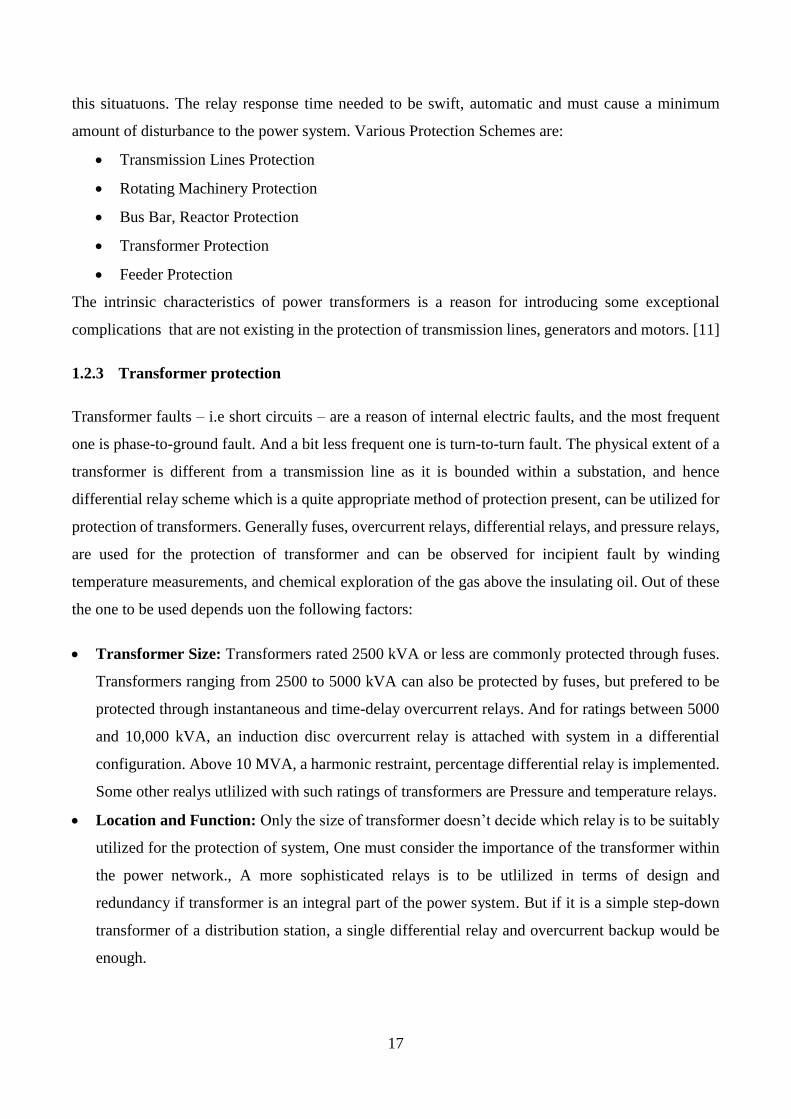
2.7 Load
Incadescent bulbs are attached as load on secondary side of transfomers. Load in connected in wye
configuration. This load can be varied in steps and burdon can be applied in any configuration to make
unbalance situation. This load will be used to create external fault and testing behavior of our proposed
relay. Load variation graphs will also be drawn by varying external load. These bulbs are connected
with holders. Details of load equipments in given below.
Load Parameters
Paramater Value
Power Rating 160Watt
Resistance 300 Ohm
Nominal Current 0.75 A
Operating Frequency 50Hz
Load configuration Wye
Table 2.4: Load Parameters
2.7.1 Holders
There are six holders through which we connect the load (Incandescent bulb) with the system. These
hodlers are responsible for fix connections of bulb with transformers. In case of any damage of load,
these bulbs are easy to replace because of use of these holders.

30
2.7.2 Incandescent Bulb
We have used Incandescent bulbs as load to the system rated 60 Watts each as normal operating load
and 100 Watts each for over current scenerio. This bulb is preffered in load due to in resistive nature.
This will help us to reduce complexity of system and will avoid leading and lagging of currents with
voltages as currents and voltages are inphase with each other in resistive load.
2.8 Connectors
Diffent type of connectors are used in our project such as three phase connector, probes for transformer
connections and their female and male connectors. Here is details discussion of all connectors used in
designed trainer.
2.8.1 Three Phase Connectors
We have used a three phase connector to connect our transformers with the main line followed by a
circuit breaker. These connectors are used to build a connection to the electrical mains with high
voltages and currents rating than household plugs and sockets. They are normally utilized in polyphase
systems, consisting of high currents, or when protection from environmental hazards is needed.
Fig. 2.6: Three phase connector
2.8.2 Connecting Probes
To connect transformers in delta wye configuration on the trainer, we have used connecting probes. In
this way it would be much easier to make the connections. These probes are easy to remove and can
be used to connect transformer in any configuration rather than delta wye.

31
2.8.3 Female Connectors
We have attached total of sixteen female connectors on the trainer to connect the system in three phase
wye to delta. These connectors are fixed on trainer and can’t be removed easily but accessible in case
of any damage. Different color schemes are used to make connections understandable and reduces
chances of error in designed trainer. Two on the primary side and two on the secondary of each
transformer and rest of four for input voltage source phases and ground.
2.9 Relays
We have used three single channel relay modules for each phase and configured them as differential
relays through Arduino. The operation of Differential relay is that it takes the phase difference of two
or more same electrical quantities when they exceeds a predetermined figure and functions
accordingly. These relays works on the principle of comparison between the phase angle and
magnitude of two or more similar electrical quantities. These relays are normally in closed state and
turned ot open state when signal is given to relay. Red leds are used to represent functionality of relays.
LEDs turns on when relay is in operating mode. A commonly used relay is shown in Fig. 2.7.
Fig. 2.7: Relay
2.10 Indicators
There are three indicators Red, Green and Yellow which get brighten when the system is connected
with the main supply. These indicators are connected as individual single phase with one phase and
ground connected to each indicator. These indicators turns on when voltage supply turns on and
voltage appears across input terminal of designed trainer. These trainers are connected parallel with
phases. Current drawn by these connectors is ignored in source code as they draw current in milli
amperes.

32
2.11 Acrylic Sheet
We have used a 6mm thick Acrylic Sheet having dimensions 18x12 cm to design the fornt side of
board for our trainer. Through laser cutting and engraving we have designed the required model for
the components placement on the sheet.
2.12 Wooden Sheet
For making a support at the backside of our trainer on which we have placed our transformers, bulbs
and holders we have used a wooden sheet. All remaining three faces and bottom of our trainer is
designed by 4mm thick wooden sheet. This sheet is used to insulate transformers and isolation of our
trainer with work station as well as other equipments.
2.13 Power Supply
A power supply is used to provide the power to Arduino mega. Power supply is rated 2A, 5V output.
This power is consumed in providing power to relays, current sensors, and LEDs that are used for
indication of relay tripping and restraining.

33
CHAPTER 3: METHODOLOGY
Working Principle
Internal Fault Behavior
External Fault Behavior
Simulations
Results

34
[ This page is kept blank intentially ]

35
3.1 Working Principle
“Differential protection based on the principle of that power input to the transformer under
normal condition is equal to power out”
Differential protection is used to protect transformer from internal fault. In some cases it fails to
operate or mal-operation due to MI currents, stationary over excitation of core, external faults in the
presence of CT saturation, power transformer ratio mismatch, operation due to high second harmonic
component. In this scenario percentage differential protection, harmonic-restrained differential
protection is used, respectively. Percentage differential protection is a developed idea of ordinary
differential protection which had made quite satisfactory solutions to the above mentioned problems.
Conventional differential technique is based on difference of currents measured by primary and
secondary side CT. Matching of CT ratios is important parameter in this technique. Ratios of current
transformers used on primary and secondary side of power transformer are selected in such a way that
secondary side of both current transformers show same current. Difference of these currents flows
through differential relay. In practical cases, exact CT ratios are not available commercially in order to
fulfill our requirements.
So, a certain value of current always passes through relay due to unbalance CT ratios. Another major
problem in this technique is CT error. Current transformers does not measure actual value but have
some error in measurement which causes flow of current in differential relay.
Fig. 3.1: Block Diagram

36
This error is minimum at low current but increases as line current increases because this error is
some percentage of primary side current of CT. At very large current this difference is significant and
consequently results in mal operation of relay. Starting inrush current is another problem in
conventional differential technique. Power transformer draws heavy starting current for magnetizing of
core. This current is seen by only primary side current transformer which creates major difference in
measurement of both currents causes ultimate false tripping of relay.
These problems are considered in proposed differential technique to provide stability to power
system. In this protection scheme spill current is not compared to constant value but it varies as input
current varies. Spill current is compared with fraction of line current. As current increases, fractional
value of current also increases. Starting inrush magnetizing current is although very high but it is
controlled by percentage differential relay. Because when input current increases specific percentage
of line current also increases and relay withstands input transient response of transformer. Similarly,
Margin of CT error as well as CT mismatch is also considered in this scheme.
3.2 Internal Fault Behavior
The faults which can be occurred inside the Transformer is known as Internal faults. There are some
types of internal fault mentioned below
Incipient Fault
Line to line Fault
Triple line Fault
Overheating
Contamination of oil
Differential protection based on current, voltage or impedance difference is termed as current
differential relay, voltage differential relay and impedance difference relay respectively. Proposed
paper describes design of current differential relay based on difference principle i.e. primary and
secondary current difference (is always zero at normal or no fault condition) and no current passes
through the relay.
Id = Ip - Is (1)
In Eq. (1), Id is current difference, Ip is primary side current, Is is secondary side current.
Ir = k (Id) (2)
37
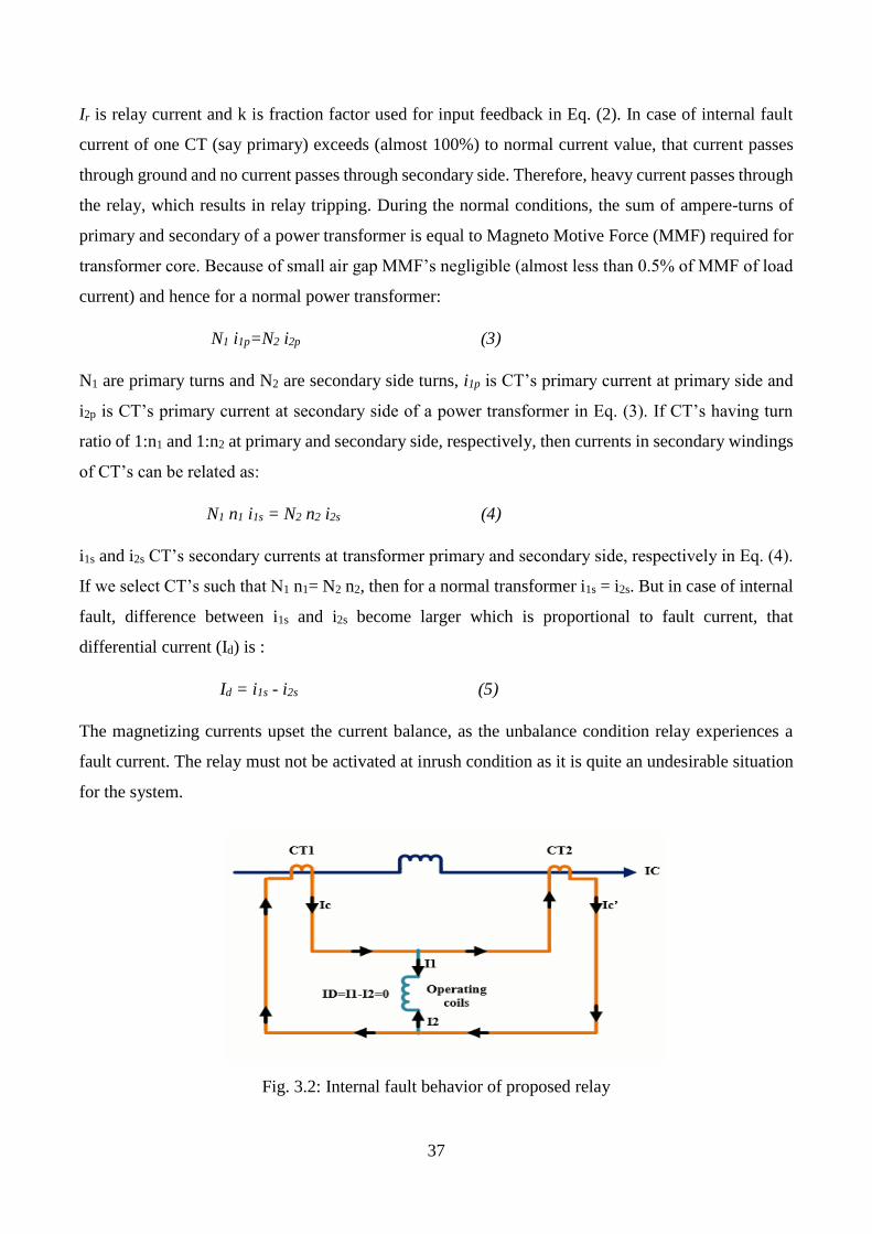
Ir is relay current and k is fraction factor used for input feedback in Eq. (2). In case of internal fault
current of one CT (say primary) exceeds (almost 100%) to normal current value, that current passes
through ground and no current passes through secondary side. Therefore, heavy current passes through
the relay, which results in relay tripping. During the normal conditions, the sum of ampere-turns of
primary and secondary of a power transformer is equal to Magneto Motive Force (MMF) required for
transformer core. Because of small air gap MMF’s negligible (almost less than 0.5% of MMF of load
current) and hence for a normal power transformer:
N1 i1p=N2 i2p (3)
N1 are primary turns and N2 are secondary side turns, i1p is CT’s primary current at primary side and
i2p is CT’s primary current at secondary side of a power transformer in Eq. (3). If CT’s having turn
ratio of 1:n1 and 1:n2 at primary and secondary side, respectively, then currents in secondary windings
of CT’s can be related as:
N1 n1 i1s = N2 n2 i2s (4)
i1s and i2s CT’s secondary currents at transformer primary and secondary side, respectively in Eq. (4).
If we select CT’s such that N1 n1= N2 n2, then for a normal transformer i1s = i2s. But in case of internal
fault, difference between i1s and i2s become larger which is proportional to fault current, that
differential current (Id) is :
Id = i1s - i2s (5)
The magnetizing currents upset the current balance, as the unbalance condition relay experiences a
fault current. The relay must not be activated at inrush condition as it is quite an undesirable situation
for the system.
Fig. 3.2: Internal fault behavior of proposed relay

38
Over excitation can also cause an unwanted tripping of the differential relays. Even in
generating plants such condition can arise when a unit connected generator is isolated while exporting
VAR. More power flows through primary than that of secondary when primary winding of a transformer
is overexcited. In case of external faults, the differential current is of very high magnitude which can
lead to relay mal-operation.
Harmonic restraint follows the fact that inrush current has a large second harmonic component
and over-excitation has also large fifth harmonic component . These harmonics may cause false
operation of differential relay.
3.3 External Fault Behavior
The Faults which are occurred outside of the Transformer is known as External Faults. Some of the
External faults in listed below
Lighting Strike
Unbalancing of the System
Over loading of system
In our case, relay will restrain on External Fault. In external faults high current passes through both
CT’s and no current passes through the relay due to zero current difference and the relay doesn’t
operate, as shown in Fig.1. However due to certain phenomena our relays can be tripped even in no
fault conditions as it let some substantial differential current to flow like: MI currents, over excitation
conditions and CT saturation.
Transformers required a large starting current to magnetize its core which usually result in MI current.
The other reasons are [13]:
Occurrence of an external fault.
Voltage recovery after clearing an external fault.
Change of the character of a fault (for example when a phase-to-ground fault evolves into a two-
phase-to-ground fault).
Out-of-phase synchronizing of a connected generator.

39
Fig. 3.3: External fault behavior of proposed relay.
We are preferring Percentage Differential Relay because the main advantage of using percentage
differential protection over ordinary is that relay compares percentage of line current with spill current.
If spill current is greater than predetermined value, it will cause trip of relay. High inrush current will
be allowed by relay as spill current is only 40 percent in case of starting of transformer. It can also
compensate the false current due to MI inrush and over-excitation.
3.4 Simulation
Simulation is done on software MATLB Simulink Fig.3.4 Shows simulation diagram of system
in which transformer is protected by percentage differential relay. Transformer is configured in wye-
delta connections for simulation model. System model consist of three phase source, current
measurements on both sides of power transformer, three phase circuit breaker on primary side for
isolation of transformer from source in case of internal fault. RL load on secondary side is used to
indicate three phase inductive load on secondary side
Fig. 3.4: Simulation Diagram

40
Differential relay is provided to system for protection of specified zone. This relay is
responsible for detection of fault within its operating zone and will trip the circuit breaker. Fig.3.5
shows simulation model of designed differential relay. This relay takes primary and secondary currents
of power transformer as input parameter and give logical output in form of Boolean variable. Designed
differential relay consists of two input ports and one output port. Input port In1 takes primary current
of all three phases of transformer while input port passes secondary side current of power transformer.
Three phase Power transformer is 2:1 step down transformer, its primary side current is 2 times less
than secondary side. Amplitude gain with gain factor 2 to balance both side currents to nullify the
difference of currents. Currents are converted into RMS values to have smooth output to make
difference operator easier and reliable.
Fig. 3.5: Designed Relay Diagram
S-R latches are used as memory device to retain last logic state of comparator. Another logic
is designed such that in case of any internal fault. Relay output is logical 1 in normal conditions and 0
in case of occurrence of fault in its operating zone. Relay output is used as input parameter for circuit
breaker on source side. Circuit breaker is normally and opens when it receives logical 0 input.
Simulation paratmeters are designed according to actual lab trainer to show exactly same results in
case of software and hardware. Table 3.1 shows parameters of simulation that are selected in this
simulataion.

41
Simulation Parameters
Paramater Value
Primary voltage phase to phase rms 400V
Secondary voltage phase to phase rms 220V
Source voltge 400V
Source Frequency 50Hz
Transformer Rating 1.5KVA
Transformer Configuration Δ/Y
Resistance 300 Ohm
Table 3.1: Simulation Parameters
3.5 Results
Results are plotted on scope to analyze behavior of system as well as relay in case of external
and internal faults. Current waveforms and relay signal is observed and results are extracted on
variation of these parameters. Results are matched with real time hardware trainer and according
to calculations.
3.5.1 Internal Fault Analysis
For internal fault, three phase fault is introduced between secondary side CT and power
transformer. Output line current waveform and relay trip signal is given in Fig.3.6 and Fig.3.7
respectively. Fault is produced at time t=0.5s to 1s. Relay gives logical 1 before fault and logical 0
after fault. Circuit breaker which is closed in normal condition opens and no further current passes
through circuit. It is clearly seen in Fig.4 that no current passes through system model after t=0.5s.
Fig. 3.6: Current Waveform during internal fault
t
Ia
Ib
Ic

42
relay tripping time is minimized and clear from both figures that relay tripping time is exactly same
as time of introducing fault.
Fig. 3.7: Relay signal during internal fault
3.5.2 External Fault Analysis
External fault is introduced between load and secondary side current transformer. Fault is
introduced at t=0.5s. Heavy current is drawn by fault during fault time. Current waveforms and relay
restrain signal are shown in Fig.3.8 and Fig.3.9 respectively. When heavy current is drawn by fault
than no significant difference on both side of currents is seen by relay. Relay is restrained and avoid
mal-operation that conventional relays often do.
Fig. 3.8: Current Waveform during external fault
Figure 3.9 shows the relay signal before and after fault analysis. Relay gives constant logical 1 output
before and after fault and keep the circuit breaker closed just like in normal condition. No tripping is
seen by relay on heavy current drawn by load. So, relay has no mal-operation on external fault and
restrains on all type of faults except internal faults.
Ia
Ia
Ib
Ic
t
t
Rel
ay L
ogic

43
Fig. 3.9: Relay signal during external fault
t
Rel
ay L
ogic

44
CHAPTER 4: HARDWARE IMPLEMENTATION
Hardware Design
Fault Introduction

45
[ This page is kept blank intentially ]

46
4.1 Hardware Design
Hardware of project is designed to make it reliable and feasible for lab performance. Input and output
port are adjustable removable and replacable according to requirement of lab task.
4.1.1 Designing on Coral Draw
Project trainer is made of wooden and acrylic sheet and designed on Coral Draw software for accuracy
and neat look. Project front side is made of designed 6mm acrylic sheet which is transparent in original
form. Cutting and drilling on acrylic sheet can be shown in Fig. 4.1. Dimensions of holes and rectangles
are taken according to size of buttons, LEDs, LCD and load buttons.
Fig. 4.1: Coral Draw Design
4.1.2 Laser Engraving
Trainer connections start from left to right in order to perform lab tasks. After making coral draw
design and verifying its dimensions on actual hardware, this design is brought to engrave on acrylic
sheet by means of Laser Engraving Technique. Holes and rectangles were verified after engraving of
sheet by fitting all components in trainer.

47
Fig. 4.2: Laser Printed Colored Design
4.1.3 Assembling of components
After engraving, this sheet is sparyed black color on front side and paper is removed from sheet. By
this technique, only engraved place remained colored and all other place remained transparent because
of paper on sheet.
Then this sheet is sprayed orange yellow color on back side. This color is chosen to make it similer to
other lab equipments. Look of trainer after coloring it on front and back side in shown in Fig. 4.2.
After coloring, this project is placed in sunshine to make it dry and shining purpose. After completing
this step, components are fitted in trainer. Components fitted trainer diagram is shown in Fig. 4.3. This
project is now quite similer to other trainers available in lab. Then all remaining sides of transformer
are fixed with front side and complete model is designed.
Fig. 4.3: Real time trainer.

48
4.1.4 Making final connections
Input output connections are made to perform a lab. This task was completed by verifying all
connections by checking continuity on digital multimeter. All connections were perfect and were able
to perform lab.
Fig. 4.4: Trainer With Input Output Connections.
In this way, an effective, reliable, low cost lab equipment for Power System Protection lab is designed
to perform differential protection scheme lab on hardware.
4.2 Fault Introduction
Faults are indroduced via push buttons in order to check it transient as well as fault behavior. Three
types of fautls are indroduced in system. Details of these faults are given below:
4.2.1 Incipient fault
Incipient transformer faults usually develop slowly, often in the form of a gradual deterioration of
insulation due to some cause. When the condition of system equipment degrades because of some
electrical, thermal or chemical effects, intermittent incipient faults begin to persist in the system.

49
4.2.2 Line to line fault
A line to line fault or unsymmetrical fault occurs when two conductors are short circuited. When fault
occurs, the 3-phase system is no longer balanced i.e. angles and magnitudes change dramatically.
4.2.3 Tripple line fault
A three phase or symmetrical fault occurs when all of three conductors are short circuited. Only 2-5
percent of system faults are symmetrical faults. If these faults occur, system remains balanced but
results in severe damage to the electrical power system equipments.

50
CHAPTER 5: CONCLUSION AND FUTURE WORK
Conclusions
Features
Applications
Future Work

51
[ This page is kept blank intentially ]

52
5.1 Conclusion
This project analyse improved form of conventional differential relay with feedback input current for
power system protection. Algorithm is based upon current difference principle and feedback of input
current as comparator. Main objective of project is to operate the relay against internal fault and
restrains in case of external fault. Idea is implemented successfully implemented on hardware trainer
that is lab trainer of power system protection lab. Applied technique compares fraction of input current
with spill current to prevent mal-operation due to magnetizing inrush current. This relay has advantage
over ordinary relay that it does not operate on starting magnetizing inrush current. Results conclude
that proposed relay model was able to distinguish between internal fault and external fault. Operating
time was reduced in this scheme. Relay is capable of discriminating fault conditions from transient
response of transformer.
5.2.1 Features
User Friendly
This project is user friendly for students providing them learnig environment in order to make students
acknowledged about differential protection basics, working principle and practical hardware
implementation. Students can also perform experiments to see behavior on changing transformer
configuration in either side. Connections are open and easy to understand with color description.
Trainer for Lab.
This trainer will be helpful for students to analyze transformer configuration waveforms of current and
voltages in either configuration. They will be able to distinguish between external and internal fault
and matching of actual values with simulated values.
Connection Reliability
Input output ports are reliable to configure in any configuration according to requirement of
experiment. Ports are used according to color of input wire to increase level of understanding and
avoiding of any inconvenience.

53
Protection Zone limited
Protection zone is limited to transformers only to avoid mal-operation. It will help students to calculate
currents in case of fault by simple power system analysis techniques.
5.2.2 Applications
This project has wide range of application due to its novelity of designing. This project has some
application as by product that makes this project feasible and reliable for future purposes. Some of its
main applications are described as follow.
Application in Power System Protection
As this project is concerned to power system protection basics, obviously it has main area of
application in power system protection. Designed relay will used in npower system protection lab as
hardware trainer for students. Microcontroller based relay has wide range of reliability to change its
source code and easy to make any relay as it used basic electrical transducers as input to relay. By
using these results and some mathematical computations. We are able to find diversity in this project
in future.
Application in Power System Analysis
As it is discussed in above sections that trainer has open ports for input connection, this feature makes
it useable in analyzing of power flow in tranformers. Students will be able to understand parameter
that varies according to variation in transformer configuration. i.e phase angle lagging in delta wye
transformer and factor of 1.731 that is included in delta wye or wye delta configuration.

54
5.2.3 Future Work
This project has wide scope of future work in both hardware as well as in software. The source code
is open to make it harmonic restraint relay using frequency spectrum analyzer and filtering third
harmonic current on starting inrush current and differentiation between fault condition and transient
response of transformer on basis of harmonics. Hardware can be improved to make it GSM based and
IOT based to send an alert to user in case of any fault so that user may be able to troubleshoot it.
GSM Technology
This project can be extended to GSM techniques to send a text or message to concerned authorties in
case of induction of any type of internal fault, In case of any serious condition, system gerenrated
phone call can be offered to concerned person and after clearance of fault. It can be auto reset to avoid
complexity.
IOT bassed data collection
This poject can be based on IOT to collect date on online data server from electrical transducers. With
this improvement, authorties will be known with relay performance and data can be used for it
maintenance in future. This data can predict its future performance on basis of artificial intelligence.
Harmonic Restrainted Relay.
This relay can be harmonic restrained by using MATLAB coding and allow to pass specific range of
frequencies to pass through circuit. This will discriminate fault from transient response.

55
REFERENCES
[1] D. D. Patel, K. D. Mistry, N. G. Chothani. "Digital differential protection of power transformer
using DFT algorithm with CT saturation consideration" , 2016 National Power Systems
Conference (NPSC), 2016
[2] Bhavesh Bhalja, R.P. Maheshwari, N.G.Chothani, “Protection and Switchgear”, Oxford University
Press, New Delhi, 2011, Ch-6, pp. 169-201
[3] S. W. Fei, X. B. Chang , Fault diagnosis of power transformer based on support vector machine
with genetic algorithm, Expert Systems with Applications 36 (2009) 11352–11357.
[4] W. Bartley, “Analysis of transformer failures,” in Proc. International Association of Engineering
Insurers 36th Annual Conference, Stockholm, Sweden, 2003.
[5] S. A. Stigant and A. C. Franlin, The J and P Transformer Book: A Practical Technology of the
Power Transformer, 10th ed., New York: Wiley, 1973.
[6] V. Behjat, A. Vahedi, A. Setayeshmehr, H. Borsi, and E. Gockenbach, “Identification of the most
sensitive frequency response measurement technique for diagnosis of interturn faults in power
transformers,” IOP Publishing (Measurement Science and Technology), Meas. Sci. Technol. 21
(2010) 075106 (14pp), pp. 1-14, 2010.
[7] W. H. Tang, K. Spurgeon, Q. H. Wu, and Z. J. Richardson, An evidential reasoning approach to
transformer condition assessments, IEEE Trans. Power Delivery, vol.19, no.4, pp. 1696- 1703,
Oct. 2004.
[8] Subhasis Nandi, A Novel Frequency Domain Based Technique to Detect Transformer Inter-turn
Faults, IEEE Trans. Power Del; Vol. 24 pp. 569-584, Feb 2008.
[9] Poljak, M. and N. Kolibas, " Computation of Current Transformer Transient Performance," IEEE
Trans. On Power Delivery, Vol.3,No.4, pp.635-645(2010).
[10] M. A. Rahman and B. Jeyasurya, “A state-of-theart review of transformer protection algorithms”,
IEEE Trans. Power Delivery, vol. 3, pp. 534–544, Apr. 2011
[11] Horowitz, IOP Publishing (Measurement Science and Technology), Meas. Sci. Technol. 21 (2010)
075106 (14pp), pp. 1-14, 2007
[12] Aktaibi, Adel, and M. A. Rahman. "A software design technique for differential protection of
power transformers" , 2011 IEEE International Electric Machines & Drives Conference (IEMDC),
2011.
[13] Stanely H. Horowitz and Arun G. Phadke. “Power System Relaying”, Virginia Technical
University, USA, Ch-8, pp-211
[14] Walter A. Elmore. “Protective Relaying Theory and Applications”. Marcel diker. second edition
2003.
[15] Kasztenny, B.; Kezunovic, M.; “An Improved Transformer Inrush Restraint Algorithm”,
Computer Applications in Power, IEEE, Volume: 11, Issue:4 , Oct. 1998, pp:39 – 45.
[16] Kasztenny, B.; Kezunovic, M.; “An Improved Transformer Inrush Restraint Algorithm”,
Computer Applications in Power, IEEE, Volume: 11, Issue:4 , Oct. 1998, pp:39 – 45.

56
APPENDIX A:
Source Code:
#include <LiquidCrystal.h>
#include <Filters.h>
// ==================== System Parameters========================
float testFrequency = 50; // test signal frequency (Hz)
float windowLength = 20.0/testFrequency;
float intercept = -0.1310; // to be adjusted based on calibration testing
float slope = 0.04099;
// ================================================================
// ===================== Variable Declaration==================
int sensorValue1 = 0;int sensorValue2 = 0;int sensorValue3 = 0;
int sensorValue4 = 0;int sensorValue5 = 0;int sensorValue6 = 0;
float current_amps1,current_amps2,current_amps3;
float current_amps4,current_amps5,current_amps6; // actual measure current
// ================================================================
unsigned long printPeriod = 1000; // in milliseconds
unsigned long previousMillis = 0;
LiquidCrystal lcd(12, 11, 5, 4, 3, 2);
// ========== Input Output pins Declaration===============
pinMode(relayPin1,OUTPUT);
pinMode(relayPin2,OUTPUT);
pinMode(relayPin3,OUTPUT);
int relayPin1=8;

57
int relayPin2=9;
int relayPin3=11;
void setup() {
Serial.begin( 9600 ); // start the serial port
// ================================================================
lcd.begin(16, 4);
// ==============Advisor and Group Members information===============
lcd.print(" Differential");
lcd.setCursor(0, 1);
lcd.print("Relay Trainer");
lcd.setCursor(0, 2);
lcd.print("Advisor:");
lcd.setCursor(0, 3);
lcd.print("Engr. Zain Shabir");
delay(3000);
lcd.setCursor(0, 0);
lcd.print("Moazzam Ali EE15");
lcd.setCursor(0, 1);
lcd.print("Walid Tariq EE15");
lcd.setCursor(0, 2);
lcd.print("Haider Ali EE15");
lcd.setCursor(0, 3);
lcd.print("Talha Khan EE15");
delay(3000);
// ================================================================
58
}
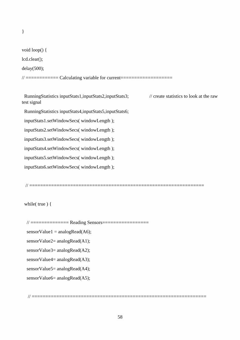
void loop() {
lcd.clear();
delay(500);
// ============ Calculating variable for current===================
RunningStatistics inputStats1,inputStats2,inputStats3; // create statistics to look at the raw
test signal
RunningStatistics inputStats4,inputStats5,inputStats6;
inputStats1.setWindowSecs( windowLength );
inputStats2.setWindowSecs( windowLength );
inputStats3.setWindowSecs( windowLength );
inputStats4.setWindowSecs( windowLength );
inputStats5.setWindowSecs( windowLength );
inputStats6.setWindowSecs( windowLength );
// ================================================================
while( true ) {
// ============== Reading Sensors=================
sensorValue1 = analogRead(A6);
sensorValue2= analogRead(A1);
sensorValue3= analogRead(A2);
sensorValue4= analogRead(A3);
sensorValue5= analogRead(A4);
sensorValue6= analogRead(A5);
// ================================================================

59
// ================ calculating slope variables====================
inputStats1.input(sensorValue1);
inputStats2.input(sensorValue2);
inputStats3.input(sensorValue3);
inputStats4.input(sensorValue4);
inputStats5.input(sensorValue5);
inputStats6.input(sensorValue6);// log to Stats function
// ================================================================
if((unsigned long)(millis() - previousMillis) >= printPeriod) {
previousMillis = millis();
//===========Calculating currents using function y=m*x+c===================
current_amps1 = intercept + slope * inputStats1.sigma();
current_amps2 = intercept + slope * inputStats2.sigma();
current_amps3 = intercept + slope * inputStats3.sigma();
current_amps4 = intercept + slope * inputStats4.sigma();
current_amps5 = intercept + slope * inputStats5.sigma();
current_amps6 = intercept + slope * inputStats6.sigma();
// ================================================================
Serial.print(" Iap ");Serial.print(current_amps1 );
Serial.print(" Ibp ");Serial.print(current_amps3 );
Serial.print(" Icp ");Serial.println(current_amps5 );

60
// ============= Displaying primary currents==============
lcd.setCursor(0,0);
lcd.print("Primary Currents");
lcd.setCursor(0,1);
lcd.print("Iap= ");
lcd.setCursor(6,1);
lcd.print(current_amps1 );
lcd.setCursor(11,1);
lcd.print("Amps");
lcd.setCursor(0,2);
lcd.print("Ibp= ");
lcd.setCursor(6,2);
lcd.print(current_amps3 );
lcd.setCursor(11,2);
lcd.print("Amps");
lcd.setCursor(0,3);
lcd.print("Icp= ");
lcd.setCursor(6,3);
lcd.print(current_amps5 );
lcd.setCursor(11,3);
lcd.print("Amps");
delay(3000);
// ================================================================
Serial.print(" Ias ");Serial.print(current_amps2 );
Serial.print(" Ibs ");Serial.print(current_amps4 );
Serial.print(" Ics ");Serial.println(current_amps6 );

61
// ============== calculating secondary currents=================
lcd.clear();
delay(500);
lcd.setCursor(0,0);
lcd.print("Secondary Current");
lcd.setCursor(0,1);
lcd.print("Ias= ");
lcd.setCursor(6,1);
lcd.print(current_amps2 );
lcd.setCursor(11,1);
lcd.print("Amps");
lcd.setCursor(0,2);
lcd.print("Ibs= ");
lcd.setCursor(6,2);
lcd.print(current_amps4 );
lcd.setCursor(11,2);
lcd.print("Amps");
lcd.setCursor(0,3);
lcd.print("Ics= ");
lcd.setCursor(6,3);
lcd.print(current_amps6 );
lcd.setCursor(11,3);
lcd.print("Amps");
delay(3000);
// ================================================================

62
// ================= Differential Relay Design===================
int id1=abs(current_amps1-2*current_amps2)*1000;
int id2=abs(current_amps3-2*current_amps4)*1000;
int id3=abs(current_amps5-2*current_amps6)*1000;
if(id1>500 || id2>500 || id3>500)
{
digitalWrite(relayPin1, HIGH);
digitalWrite(relayPin2, HIGH);
digitalWrite(relayPin3, HIGH);
// ================================================================
}
}} }

63
APPENDIX B:
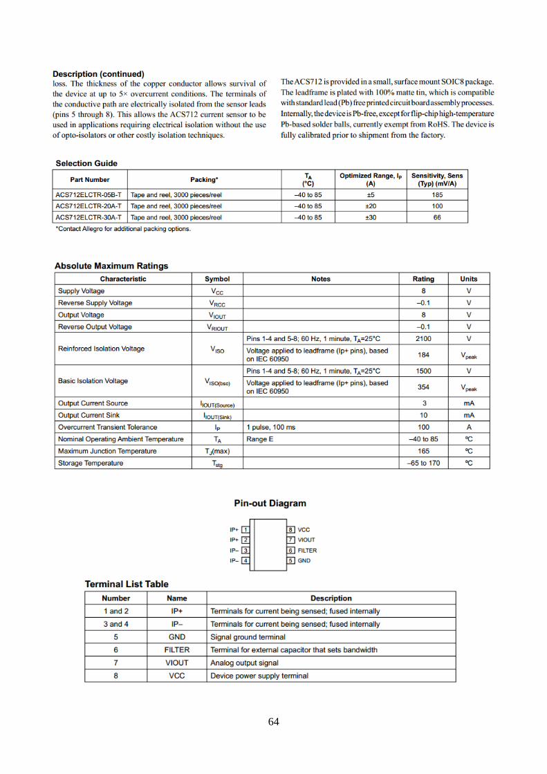
Datasheet of ACS712:
64

65

66


