
Implementation And Performance Analysis of ATM
Adaptation Layer Type 2
by
Vishal Moondhra
B.E. University of Mysore, India
Submitted to the Department of Electrical Engineering and Computer Science and the
Faculty of the Graduate School of the University of Kansas in partial fulfillment of the
requirements for the degree of Master of Science.
Professor in Charge
Committee Members
Date of Acceptance

Abstract
In the recent years, Asynchronous Transfer Mode has been used to implement high speed net-
works providing multi-gigabit services for multimedia applications. However, Mobile systems
necessitate the adaptation of the ATM paradigm to low bandwidth, high frequency, noisy links
which are expensive. ATM protocol aspects have thus been modified to accommodate these
links and provide high utilization of the limited bandwidth. These links are characteristically
wireless, with bandwidths in the several kilobits.
In this project, one such modification of ATM, the ATM Adaptation Layer Type 2 was
implemented and it’s performance measured. The implementation used the NarrowBand ATM
protocol as a basis to implement and test the higher layers of the AAL2, along with a simple
AAL2 Negotiation Protocol. The AAL2 protocol calls for multiplexing many low bit rate fixed
length ’channels’ on a single ATM Virtual Connection, and the ANP is used to setup, monitor
and tear down these connections. To test the protocol, voice channels were setup between two
hosts on a NarrowBand network. The voice application used Sinusoidal Transfer Protocol to
compress and decompress recorded voice.
i

Acknowledgments
I would like to thank Dr. Joseph Evans, my advisor, for his help and guidance through this
project, from it’s conception to it’s final testing. I would also like to thank him for guiding me
through my graduate course work.
I would like to extend my thanks to Professor Victor Frost, and Dr. Gary Minden for con-
senting to serve on my committee.
I would like to thank my project mates Eric Lindsley for helping me understand the intri-
cacies of Linux and guiding me through the NarrowBand driver, Lei Zhu for developing the
testing suite for the project, and Sachin Seth for unraveling the mysteries of STC.
I also acknowledge my various colleagues and friends at ITTC, particularly Shyam Murthy,
for allowing to weep on his shoulder with frustration and Balaji Srinivasan for patiently putting
up with my technical doubts. I particularly want to thank Vrushali Tembe for making the
Lawrence experience unforgettable.
ii

Contents
1 Introduction 1
1.1 The Implementation Environment . . . . . . . . . . . . . . . . . . . . . . . . 2
1.2 Contributions of Other Project Members. . . . . . . . . . . . . . . . . . . . . 3
1.3 Organization of This Document . . . . . . . . . . . . . . . . . . . . . . . . . 3
2 Basics 5
2.1 Computer Networking Principles . . . . . . . . . . . . . . . . . . . . . . . . . 5
2.2 Asynchronous Transfer Mode. . . . . . . . . . . . . . . . . . . . . . . . . . 6
2.2.1 ATM Adaptation Layers . . . . . . . . . . . . . . . . . . . . . . . . . 8
2.2.2 ATM Signaling . . . . . . . . . . . . . . . . . . . . . . . . . . . . . . 8
2.2.3 ATM Addressing . . . . . . . . . . . . . . . . . . . . . . . . . . . . . 9
2.3 Narrowband ATM . . . . . . . . . . . . . . . . . . . . . . . . . . . . . . . . . 10
2.4 Overview of Linux . . . . . . . . . . . . . . . . . . . . . . . . . . . . . . . . 11
2.4.1 Networking Under Linux . . . . . . . . . . . . . . . . . . . . . . . . . 11
2.4.2 Interrupts and Interrupt Drivers . . . . . . . . . . . . . . . . . . . . . 14
2.4.3 IOCTLs . . . . . . . . . . . . . . . . . . . . . . . . . . . . . . . . . . 14
2.4.4 Multiport Serial Cards . . . . . . . . . . . . . . . . . . . . . . . . . . 14
3 Switching and Signaling 16
3.1 Switching in ATM . . . . . . . . . . . . . . . . . . . . . . . . . . . . . . . . . 16
3.1.1 User Plane . . . . . . . . . . . . . . . . . . . . . . . . . . . . . . . . 16
3.1.2 Control Plane . . . . . . . . . . . . . . . . . . . . . . . . . . . . . . . 17
3.1.3 Management Plane . . . . . . . . . . . . . . . . . . . . . . . . . . . . 17
iii

3.2 Cell Switch Fabric . . . . . . . . . . . . . . . . . . . . . . . . . . . . . . . . 17
3.2.1 Shared Memory Fabrics . . . . . . . . . . . . . . . . . . . . . . . . . 18
3.2.2 Shared Medium Fabrics . . . . . . . . . . . . . . . . . . . . . . . . . 18
3.2.3 Fully Interconnected Fabrics . . . . . . . . . . . . . . . . . . . . . . . 20
3.2.4 Space Division Fabrics . . . . . . . . . . . . . . . . . . . . . . . . . . 20
3.3 Software Switching . . . . . . . . . . . . . . . . . . . . . . . . . . . . . . . . 21
3.3.1 Switch Structure . . . . . . . . . . . . . . . . . . . . . . . . . . . . . 21
3.3.2 The NATM Driver . . . . . . . . . . . . . . . . . . . . . . . . . . . . 22
3.3.3 The MicroSwitch Driver . . . . . . . . . . . . . . . . . . . . . . . . . 24
3.3.4 Q.Port . . . . . . . . . . . . . . . . . . . . . . . . . . . . . . . . . . . 24
3.3.5 The NATM Fabric . . . . . . . . . . . . . . . . . . . . . . . . . . . . 25
3.4 Signaling on the End System . . . . . . . . . . . . . . . . . . . . . . . . . . . 27
3.4.1 ATMSIGD . . . . . . . . . . . . . . . . . . . . . . . . . . . . . . . . 27
3.4.2 ILMID . . . . . . . . . . . . . . . . . . . . . . . . . . . . . . . . . . 29
3.4.3 ATMARPD and ATMARP . . . . . . . . . . . . . . . . . . . . . . . . 29
4 Protocols and Data Structures 30
4.1 ATM Adaptation Layer 2 . . . . . . . . . . . . . . . . . . . . . . . . . . . . . 30
4.1.1 General Framework of AAL2 . . . . . . . . . . . . . . . . . . . . . . 30
4.1.2 The Common Part Sublayer . . . . . . . . . . . . . . . . . . . . . . . 32
4.1.3 AAL2 CPS Procedure . . . . . . . . . . . . . . . . . . . . . . . . . . 35
4.1.4 AAL2 Negotiation Protocol (ANP) . . . . . . . . . . . . . . . . . . . 40
4.2 Data Structures . . . . . . . . . . . . . . . . . . . . . . . . . . . . . . . . . . 42
4.2.1 Socket Structure . . . . . . . . . . . . . . . . . . . . . . . . . . . . . 42
4.2.2 Data Buffers (SKBs) . . . . . . . . . . . . . . . . . . . . . . . . . . . 43
4.2.3 Virtual Channel Structure (VCC). . . . . . . . . . . . . . . . . . . . . 43
5 Implementation and Results 45
5.1 Implementation . . . . . . . . . . . . . . . . . . . . . . . . . . . . . . . . . . 45
5.1.1 AAL2 Driver Support Implementation . .. . . . . . . . . . . . . . . . 45
5.1.2 AAL2 Negotiation Protocol Implementation . . . . . . . . . . . . . . . 47
iv

5.1.3 ANP Procedure . . . . . . . . . . . . . . . . . . . . . . . . . . . . . . 52
5.2 User Interface . . . . . . . . . . . . . . . . . . . . . . . . . . . . . . . . . . . 55
5.2.1 The SOAAL2BLOCK socket option . . . . . . . . . . . . . . . . . . 55
5.2.2 The SOAAL2SETCH socket option . .. . . . . . . . . . . . . . . . 56
5.2.3 The SOAAL2SETCHLEN socket option . . . . . . . . . . . . . . . . 56
5.2.4 The SOAAL2SETBW socket option . .. . . . . . . . . . . . . . . . 56
5.2.5 The SOAAL2SETTO socket option . . .. . . . . . . . . . . . . . . . 56
5.2.6 The SOAAL2UNBLOCK socket option . . . . . . . . . . . . . . . . 56
5.3 Results . . . . . . . . . . . . . . . . . . . . . . . . . . . . . . . . . . . . . . . 56
5.3.1 Comparison of Bandwidth Utilization . .. . . . . . . . . . . . . . . . 57
5.3.2 Multiple Channels .. . . . . . . . . . . . . . . . . . . . . . . . . . . 60
5.3.3 Switch Characteristics . . . . . . . . . . . . . . . . . . . . . . . . . . 66
5.3.4 Setup Times . . . . . . . . . . . . . . . . . . . . . . . . . . . . . . . . 66
6 Conclusions 69
6.1 Summary . . . . . . . . . . . . . . . . . . . . . . . . . . . . . . . . . . . . . 69
6.2 Conclusions . . . . . . . . . . . . . . . . . . . . . . . . . . . . . . . . . . . . 70
6.3 Future Work . . . . . . . . . . . . . . . . . . . . . . . . . . . . . . . . . . . . 70
A Forward Error Correction Scheme 72
B Pseudo-Code For AAL2 Connections 74
v

List of Figures
2.1 ATM Cell Structure at the UNI . . . . . . . . . . . . . . . . . . . . . . . . . . 7
2.2 ATM Address Formats . . . . . . . . . . . . . . . . . . . . . . . . . . . . . . 9
2.3 NATM cell structure . . . . . . . . . . . . . . . . . . . . . . . . . . . . . . . 10
2.4 State Diagram for Socket Open . . . . . . . . . . . . . . . . . . . . . . . . . . 13
3.1 Shared Memory Switch . . . . . . . . . . . . . . . . . . . . . . . . . . . . . . 19
3.2 Shared Medium Switch . . . . . . . . . . . . . . . . . . . . . . . . . . . . . . 19
3.3 Fully interconnected switch . . . . . . . . . . . . . . . . . . . . . . . . . . . . 20
3.4 4x4 Banyan network . . . . . . . . . . . . . . . . . . . . . . . . . . . . . . . 21
3.5 The NATM Switch - Block Structure . . . . . . . . . . . . . . . . . . . . . . . 23
3.6 Q.Port SCC . . . . . . . . . . . . . . . . . . . . . . . . . . . . . . . . . . . . 25
3.7 NATM Fabric and interactions . . . . . . . . . . . . . . . . . . . . . . . . . . 26
3.8 Linux ATM Signaling . . . . . . . . . . . . . . . . . . . . . . . . . . . . . . . 27
4.1 AAL2 Structure, interfaces and connection. . . . . . . . . . . . . . . . . . . . 31
4.2 AAL2 CPS Packet Format . . . . . . . . . . . . . . . . . . . . . . . . . . . . 32
4.3 Translating CPS-SDUs to ATM SDUs . . . . . . . . . . . . . . . . . . . . . . 34
4.4 AAL2 CPS PDU Format . . . . . . . . . . . . . . . . . . . . . . . . . . . . . 34
4.5 AAL2 CPS Transmitter Flow (part 1) .. . . . . . . . . . . . . . . . . . . . . 36
4.6 AAL2 CPS Transmitter Flow (part 2) .. . . . . . . . . . . . . . . . . . . . . 37
4.7 AAL2 CPS Receiver Flow (part 1) . . .. . . . . . . . . . . . . . . . . . . . . 39
4.8 AAL2 CPS Receiver Flow (part 2) . . .. . . . . . . . . . . . . . . . . . . . . 40
4.9 AAL2 Negotiation Protocol communication architecture . . . . . . . . . . . . 41
5.1 Initial channel setup to remote end system. . . . . . . . . . . . . . . . . . . . 52
vi
5.2 Subsequent channel setup to same end system . . . . . . . . . . . . . . . . . . 53
5.3 Throughputs at 9.6 kbps . .. . . . . . . . . . . . . . . . . . . . . . . . . . . 57
5.4 Throughputs at 19.2kbps . .. . . . . . . . . . . . . . . . . . . . . . . . . . . 58
5.5 Throughputs at 38.4kbps . .. . . . . . . . . . . . . . . . . . . . . . . . . . . 59
5.6 Multiple channels at 9.6kbps. . . . . . . . . . . . . . . . . . . . . . . . . . . 61
5.7 Multiple channels at 19.2kbps. . . . . . . . . . . . . . . . . . . . . . . . . . 62
5.8 Multiple channels at 38.4kbps. . . . . . . . . . . . . . . . . . . . . . . . . . 63
5.9 AAL2 PDU distributions . .. . . . . . . . . . . . . . . . . . . . . . . . . . . 65
5.10 Comparison of Setup Times . . . . . . . . . . . . . . . . . . . . . . . . . . . 67
vii

Chapter 1
Introduction
In recent years, the area of telecommunication has witnessed unprecedented and explosive
growth. This is particularly true of multimedia services. A huge amount of research and devel-
opment effort has been expended in the area of providing these mixed voice, video and sound
services over high bandwidth wireline networks, be they copper wire based or fiber based. How-
ever, there exists an opposite area of concern for research, and that is Mobile Systems. Mobile
systems are typically very different from their static counterparts, due the fact that they cannot
rely on dependable, high speed wireline networks to connect them to the world. They rely,
instead on fairly expensive, noisy and limited bandwidth wireless channels. Providing connec-
tivity and multimedia services to these low bit rate, wireless units is an area that is only now
coming into it’s own. ATM, or Asynchronous Transfer Mode, has been synonymous with high
speed, fiber based networks, with low error rates and very high (into the Gigabits) throughputs.
Thus, using ATM for low bit rate, noisy wireless channels requires us to question the fundamen-
tal aspects of ATM networking, and evolve a strategy to adapt it successfully to the demands of
this environment.
This project is designed to implement and evaluate the performance of one such adaptation
of ATM in order for it to better perform at low speeds. When low, but constant bit rate (CBR)
voice channels need to be established over low bandwidth lines, a lot of the basic assumptions
behind the various ATM Adaptation layers are found to be inapplicable. So, the ATM Adap-
tation Layer Type 2 (or AAL2) was introduced as a concept early in 1997. This adaptation
layer was specifically targeted towards maximizing the utilization of the available bandwidth,
1

by small (< 64 byte) packets at a constant bit rate. AAL2 was designed to work at link rates
below 64 kbps, and to support multiple users over single Virtual Channel setup between hosts,
to optimize both the bandwidth usage of these links, as well as to make these links cost effective
to the end user. An earlier version of AAL2, defined in 1991 along with AAL Types 1, 3, 4 and
5 was meant for video transmission, but failed to take off. In a slightly confusing move, the
ATM Forum decided to reuse the name for an AAL designed for low bit rate CBR traffic.
As of the writing of this document, the various nuances of the new adaptation layer are still
under discussion, but the basic ideas are in place, and the theoretical performance of some of
the sections of the proposal are being established.
1.1 The Implementation Environment
The project we were contracted to do for Rome Labs, Wireless ATM Adaptive Voice Data Net-
works, provided an excellent test bed to implement and evaluate AAL2. The project consisted
of providing a low bit rate wireless data and voice network. The network consisted of switches,
and end systems acting as a combination PC and phone. The phone would use a Sinusoidal
Transform Coder (STC) to compress sampled voice to acceptable bit rates, and the PC would
be used as a client to the network, handling calls and providing data transfer facilities. The
STC was developed by Lincoln Labs, and was initially targeted to specific hardware using em-
bedded TI DSPs. However, the code was later modified to run under standard Unix, using the
standard sound hardware found on most commercial platforms. The PCs were expected to be
running the Linux Operating System, and a specific driver needed to be written to implement
networking using the standard serial port of the PC. The switches were designed on PCs, also
running the Linux Operating System. Switching functions were to be achieved using hardware
that provided multiple serial ports on a single hardware interrupt line.
The Linux driver used to implement ATM over the serial port was developed as part of the
Rome Labs project. I was involved in modifying this driver to support AAL2 at the low level. I
was also involved in providing an AAL2 Negotiation Protocol, which facilitated the setting up
and tearing down of individual AAL2 channels over the network. This support was provided
in the form of a daemon running partially in the user space and partially in the kernel space of
the operating system. Further, I was involved in designing and implementing the Linux based
2

Software ATM Switch. This switch used a basic kernel level switching driver developed for
Linux for a different project as the fabric. It also used a modified version of a commercial call
control application called Q.PortTM , developed by BellCore.
1.2 Contributions of Other Project Members
The Rome Labs project consists of three other members. Erik Lindsley designed and developed
the low level ATM driver for Linux called the ATMSL driver, to implement a version of the
ATM protocol over low speed serial links. The ATMSL Driver interfaces on the top with the
standard Linux ATM driver. Lei Zhu helped design the modifications to standard ATM for
low speed and high error rate channels. The resulting protocol is called Narrowband ATM, or
NATM. He also designed various testing suites to test the driver under conditions of high error
rates, and a Forward Error Correction (FEC) mechanism for the ATM cells. Sachin Sheth, the
newest member of the project group is handling the adaptive networking section of the project,
and the STC related implementation details.
1.3 Organization of This Document
This document contains five chapters after this brief introduction.
Chapter 2 contains the background literature essential to understanding the basic tenets
behind ATM, Linux, Drivers etc. This chapter includes relevant details that went into modifying
ATM to the NATM protocol, and networking under Linux.
Chapter 3 contains an overview of standard switching techniques employed while design-
ing ATM switches, an overview of the ATM signaling procedures, and a description of the
implementation of the NATM Fabric, to facilitate software switching using Q.Port.
Chapter 4 consists of a detailed description of the ATM Adaptation Layer 2, the AAL2
Negotiation Protocol, and generic flow diagrams of the involved processes.
Chapter 5 consists of the details of the implementation of both the low level AAL2 sup-
port, and the user level AAL2 Negotiation Protocol. The latter half of the chapter is devoted
to performance evaluation of the implemented system, and comparisons with other, existing
solutions.
3

Chapter 6 describes the conclusions and future work required in the project.
Appendix Ahas a brief description of the FEC coding used in the Narrowband ATM driver.
Appendix Bhas a section of psuedo-code that can be used as an example to set up an active
AAL2 channel on a compliant host.
4

Chapter 2
Basics
This chapter is devoted to overviews of the basics required to understand networking in gen-
eral, and specifically Linux ATM networking. One of the major concerns while designing and
implementing the AAL2 test bed was the cost and availability of the software infrastructure
involved. Linux was chosen as the operating system to design the switch on because of it’s
modular nature, freely available source code, and inherent robustness. The hardware infras-
tructure included a Multiport serial card, and wireless modems or RS-232 serial cables which
connected the various serial ports of the card to hosts.
Section 2.1 in this chapter describes the basic principles behind computer networking. Sec-
tion 2.2 describes Asynchronous Transfer Mode (ATM), and it’s aspects like ATM Adaptation
Layers (AALs) and ATM signaling. Section 2.4 describes the operating system Linux, and
networking under Linux.
2.1 Computer Networking Principles
Computer Networking involves connecting computers to each other, by various means, so that
they form a network. The major goals of Computer Networking are to share resources between
computers located physically apart, and allow users of these computers to communicate with
each other. Also, computer networks help in improving reliability of a system, as dependencies
on single, central units is reduced. Networking helps conserve resources and reduce expense,
as computing resources otherwise available to restricted number of people are now more acces-
sible.
5
Networks are of various kinds, and are implemented using different Protocols. A protocol
is a set of rules that determine how the computers will talk to each other over the network.
The rules determine things like the order and format of message to be sent between connected
computers, the setting up and tearing down of these connections, and various other aspects.
Networks are modeled on the OSI reference model, which has a layered structure, consisting
of 7 layers. Most practical implementations fuse the functionality of the various layers, so that
practical networks have 3 or 4 layers [1]. Each of these layers pertains to a function in the
network. Typically, a network consists of a Physical layer, dealing with representing bits on a
transmission medium, the Data Link Layer, which abstracts the physical link to make it appear
error free to the higher layers. The Network layer is concerned with routing data packets from
source to destination, the Sessions Layer establishes connections between processes on the end
points. Finally, applications need to be running on end points that can handle or generate the
required data. Networks are usually composed of hosts, which are the computers that connect
to each other, and Switches, that make the connections physically possible. A switch consists of
Ports, to which hosts and other switches are connected. Data coming into a port on the switch is
usually directed out another port. This ’Switching Function’ is performed on the basis of some
rules, or setup procedures.
2.2 Asynchronous Transfer Mode
Asynchronous Transfer Mode, or ATM, has rapidly emerged as a protocol of choice for the de-
mands made by multimedia networks [2]. ATM networks have many distinct features that help
maintain it’s edge over other network protocols, especially in the area of high speed network-
ing carrying different kinds of data. ATM transfers data between network elements using fixed
sized ’packets’, or cells. These cells are 53 bytes, or octets long, and carry two kinds of infor-
mation - information pertaining to the path in the network, and the data that they transport along
the path. The cells are partitioned into 5 octets of header, which is the path information, and
48 octets of data payload. One octet in the header is used as a Cyclic Redundancy Check over
the remaining four octets, in order to assure the integrity of the header. The ATM cell structure
is shown in figure 2.1. ATM cells have no sequence numbers since the protocol guarantees
in-sequence delivery. The cells themselves contain minimal routing information. The routes
6

for the cells are setup prior to the start of data transfer. A physical link between two entities
consists of many ’virtual’ channels. A route between two hosts in an ATM network, separated
by switches is thus a collection of Virtual Channels or VCs between them. VCs are setup by a
Signaling Protocol. ATM uses Out of Band Signaling, i.e. a separate signaling channel is dedi-
cated across the network, and both switches as well as hosts use this channel to setup, monitor
and tear down the other VCs. Cells carry Virtual Channel Identifiers, or VCI numbers in the
header, that establish the channel they are traveling on. These VCI numbers are only significant
on a link to link basis. New VCI numbers are assigned when the cell passes from one link to
another on it’s way to the destination. In the future, it is envisioned that broadband networks
will have to support semi-permanent connections to transport a large number of simultaneous
connections, called Virtual Paths. Thus each cell also carries a Virtual Path Identifier, or VPI
number. A VPI/VCI pair uniquely identifies a cell on a given link. Other information in the cell
header consists of the CLP bit, which is a means of attributing priority to the cell. Cells with the
CLP bit 0 are dropped first when the network is congested. The GFC field is used by switches
to perform flow control, although actual application is limited.
7 6 5 4 3 1
1
4
2
5
3
28
CLP
HEC
VCI
VPI
VPI
VCI
VCI PTI
GFC
PAYLOAD
6
53
Figure 2.1: ATM Cell Structure at the UNI
The PTI or Payload Type Indicator bits indicate the type of ATM protocol this cell belongs
to, and are also used for rudimentary network management.
7

2.2.1 ATM Adaptation Layers
Above the ATM Layer lies the Adaptation layer, which provides for the transformation of the
higher-layer service - voice, video, data - into a form suitable for transmission over the ATM
infrastructure. The AAL preserves timing relationships for traffic requiring it (voice, for exam-
ple). The following AAL types are defined by the ATM Forum:
� AAL1 is used to support Constant Bit Rate (CBR) connections across the ATM network.
Incoming data is placed in an ATM cell along with a 3 bit sequence number, a 4 bit
CRC. The remaining bit in the first byte is used over a series of cells to indicate, among
other things, timing recovery information and whether or not the AAL1 connection is
structured.
� AAL2 is used to multiplex many low bandwidth CBR channels over a single VC. Each
channel has a 3 byte channel overhead, including a Channel Id Number, and a length
indicator. Up to 64 channels can be multiplexed over a VC, and individually setup and
torn down. AAL2 needs a separate AAL2 Negotiation Protocol (ANP), as is discussed in
section 4.1.1.
� AAL3/4 is an obsolete adaptation standard used to deliver connectionless and connection-
oriented data over the ATM network. This AAL has a substantial overhead in terms of
sequence numbers and multiplexing indicators, and is rarely used.
� AAL5 is an outgrowth of the data communication industry, and is optimized for data
transport. The PDU is broken up into ATM cell segments, and the last ATM cell carries
an indication in the PTI. The last cell is padded out to 48 bytes, and contains a CRC over
the entire PDU, and the length of the PDU.
2.2.2 ATM Signaling
When two nodes in an ATM network want to communicate, they first need to establish a virtual
connection [3]. These connections can be either provisioned, in which case they are called
Permanent Virtual Circuits or PVCs, or established on demand, in which case they are called
Switched Virtual Circuits or SVCs. PVCs are analogous to leased lines in a phone network,
8

while SVCs are analogous to making a call over a phone network. SVCs require signaling sup-
port on the originating node, the switches that lie along the path, and the on terminating node.
ATM networks have dedicated Signaling Channels, which implement connection setup and tear
down between hosts. The signaling is of two kinds - User Network Interface, or UNI, and
Network Network Interface, NNI. When a user on a host wants to setup a connection, the UNI
entity on the host sends a setup message to the Network. The Network, which is a collection
of switches, will use NNI to build a route between the destination, and the final leg between
network and the destination host will again use UNI to setup the connection. The ATM Forum,
a group of industrial representatives and academicians are responsible for establishing and stan-
dardizing the various aspects of the ATM protocol. The Forum has currently published Version
4.0 of UNI signaling, and has recently published the PNNI specification, which is Public NNI.
Before PNNI was standardized, ATM networks implemented the Interim Interswitch Signaling
Protocol, or IISP, as an interim solution. The work on this project has used and extended UNI
3.1 on the hosts, and IISP 1.0 to setup connections between switches.
2.2.3 ATM Addressing
IDP
ESIHO-DSP
DSPIDI
(c) E.164 FORMAT
E.164AFI SEL
(b) ICD FORMAT
IDPDSP
HO-DSPICD ESI
IDI
SELAFI
SEL
IDPDSP
HO-DSPDCC ESI
IDI
AFI
(a) DCC FORMAT
Figure 2.2: ATM Address Formats
9

For the purposes of SVCs established by the signaling procedure, each ATM end system is
assigned a unique 20 byte address. This address is modeled after the address format of the OSI
Network Service Access Point, as specified in the ISO 8348 document. The address is divided
into the Initial Domain Identifier (IDI) and the domain Specific Part (DSP) parts (Fig 2.2). The
IDI has three formats, and the DSP is split into two parts - the High Order DSP (HO-DSP),
and the low order part consisting of the End System Identifier (ESI) and the Selector (SEL).
The ESI is typically the hardware address of the end system and the SEL is used to distinguish
multiple interfaces with the same hardware address. The three IDI formats are the DCC, or the
Data Country Code, the ICD or the International Code Designator, and theE:164 which is in
the ISDN format. The reader is directed to [3] for a more details. The IDI in private networks
is the switch address.
2.3 Narrowband ATM
7 6 5 4 3 1
1
2
3
28
VCIEnd0 End5
ACK TX Seq
PAYLOAD
26
ACK SeqEnd5: end of AAL5 PDU
End0: end of ATM cell
Figure 2.3: NATM Cell Structure [11]
The actual protocol used in the project was a deviation from the standard ATM as described
above. The modifications were made to solve some of the problems related to low speed, wire-
less links carrying mixed real time (voice) and non-real time (data) traffic. The two main prob-
lems that needed attention were the high error rate - 1 random error in every 1000 bits, added
to burst errors due to channel fading, and the transmission latency of the cells. Simulations
showed that the error rates would cause frequent cell loss at an impractical rate. The modifica-
tions made resulted in a Narrowband ATM [erik](Fig 2.3), or NATM protocol, which had a cell
10

length of 24 payload and 2 header bytes, as against the standard 53 byte cell, and a geometric
Hamming Code based Forward Error Correction (FEC, Appendix A) scheme that added a 50%
redundancy to each cell. The smaller cell size reduced the transmission latency to acceptable
levels for real time traffic, and FEC helped reduce the errors to acceptable levels without re-
transmissions making a mockery of the throughput. The VCI space has been reduced from216
to 26, the VPI value is always assumed to be 0. The second byte of the header is used for an
optional ARQ protocol, to further reduce errors by automatic retransmission of cells lost due to
errors in the channel.
2.4 Overview of Linux
Linux is a Berkeley Systems Division (BSD) Unix clone designed primarily for PCs, although
it now has many versions that run on all major platforms. The Linux OS development is an
ongoing effort, which was started by Linus Torvalds. It is meant to be a clean re-implementation
of the standard BSD variety, and is freely available along with the source. Kernel version 2.0.25
was used in this project. Linux supports the BSD Socket Interface.
2.4.1 Networking Under Linux
The BSD socket interface is a method for interprocess communication (IPC). Processes that
wish to establish communication with other processes running on the same or different ma-
chines, open sockets of a particular type, called a Family. After a socket is opened, the process
can eitherlisten on it, waiting for another process to start communicating, orconnect these
sockets to other processes. A socket that is used to listen is said to be Passive, while the one that
connects is said to be Active. For communication to occur, a pair of active and passive sockets
is needed. Families like AFINET, and AFATMPVC or AF ATMSVC connect to a remote
machine using the protocol address of that machine. After putting a socket into the listen mode,
a process usually waits toaccept an incoming connection. Since potentially a large number of
sockets could be open and waiting to get a connection, most protocol families have unique ways
of identifying sockets that they want to connect to. In ATM, there are two sets of numbers, the
’Broadband High Layer Information’ and ’Broadband Low Layer Information’ structures as-
11

sociated with the sockets. These are set to specific values by both the active and the passive
socket. Connection is established when both information sequences match. In some cases, it is
not necessary to designate the sockets in uniquely. However, most practical applications require
it. The bind function call is used to bind the socket to a unique identifier. The identifier is
supplied as part of an address structure. This structure also contains the local protocol address
of the host. Once the connection is established between two sockets, data transfer can occur by
theread andwrite system calls (Figs 2.4(a), 2.4(b) [4]).
Sockets of various families have optional parameters, called socket options. Most times,
the default socket options need to be modified to suit individual needs. These options are set
and read using thesetsockopt andgetsockopt calls. Usually, socket options are set before
connection, but that is not necessary. After connection, the sockets are bidirectional, in the
sense that either socket can read or write, eliminating the distinction between active and passive
sockets. A process may have many sockets open, and may not wish to block itself on only one
of these. To get around the problem of listening to more than one socket at a time, the process
builds a list of open sockets it wants to listen to, and performs aselect on this list. When
any socket receives data, the process is alerted. The process can then find out which of the
sockets on the list has incoming data, and do a read on that. When the application wants to stop
communication, it simply performs aclose on the socket. The drivers are then responsible to
tear down the connection, and deallocate any resources that were reserved for this connection.
Drivers under Linux implement the functions described above. These functions are invoked by
the kernel when a process opens an socket and starts trying to connect. A different driver is
needed for each of the protocols, and the drivers are expected to handle the protocol specific
nature of the connection. The driver that handles the ATM protocol is split into two parts -
the high and low level drivers. The high level driver, implemented by Werner Almesberger of
Laboratorie de Reseaux de Communication, Switzerland [4], handles the Transport and most
of the Network Layer of the protocol. The Low level driver implements the Data Link layer.
The low level drivers are specific to the hardware, and provide a layer of abstraction to the high
level. This driver is usually hardware specific, and manipulates registers on the hardware that is
used to physically connect to the network.
12

BOUND
LISTENINGCONNECTED
socket
close
close
close
new socket
accept
CREATED
listen
bind
listen
(OPTIONAL)
(a) Passive open of a socket
BOUND
CONNECTED
socket
close
close
close
CREATEDbind(OPTIONAL)
CONNECTINGconnection
complete
blocking
connect
non-blockingconnect
connect
blocking
connect
error
non blocking
connecterror
connecterror
connect
connect
error
connecting
(b) Active open of a socket
Figure 2.4: State Diagram for Socket Open
13

2.4.2 Interrupts and Interrupt Drivers
The low level drivers are usually implemented to handle Interrupts, that are generated by the
hardware. Whenever any peripheral device or hardware wants attention from the CPU, for
instance when new data has arrived at the ATM card, it generates an Interrupt to the CPU. The
CPU then invokes a special software routine designed to service the hardware, and this is called
the Interrupt Service Routine. During boot time, ISRs are configured in the kernel, so that the
kernel knows what ISR is handling what interrupt. This is critical, since the correct ISR needs
to be invoked for each interrupt. Standard ATM cards use the PCI bus, which has a common
interrupt for all the cards on it. However, other ISRs need to register themselves, and inform
the kernel the interrupt number for which they need to be evoked. In the case of low level ATM
drivers, the ISRs handle the Data Link level ATM protocol, and hand the data up to the high
level driver through a well defined and consistent interface.
2.4.3 IOCTLs
An IOCTL or I/O control system call is used to manipulate a device driver. It provides a method
for user applications to change the behavior or characteristics of the driver. The ioctl system
call has a uniform interface at the kernel. However, each call has an argument that targets the
call to a specific device driver, and indicates to the driver what task needs t be performed, or
what variable needs to be set. For example, an ioctl may be used by a program to change the
speed of the serial port. IOCTL calls are performed by opening special files in the file system,
called device files. Each of these files is connected to a device driver.
2.4.4 Multiport Serial Cards
Traditionally, a serial port on a computer has an interrupt associated with it. The switching
function requires a user to be able to connect hosts to the switch, and connect this switch to
other switches so that the hosts can access each other and the rest of network. This requires
multiple ATM ”ports” on the switch. Each port handles both input and output, and has either
a host or another switch connected to it. Since each ATM port is a serial port on the machine,
the number of interrupts required for this task soon becomes prohibitive. The alternative is to
use Multiport serial cards. These cards offer up to 16 serial ports on one interrupt. The ISR
14

associated with the card reads a special register on the card to determine which of the multiple
ports needs servicing. These cards also provide a host of other features. Each port on the card
can usually support serial data transfer rates of up to 115 kbps. They also have extensive built-in
Modem support. For the AAL2 Switch, the Cyclades card was chosen. The source code for the
driver for this card is available with the Linux distribution, which was modified to handle ATM
traffic over each of the ports.
15

Chapter 3
Switching and Signaling
3.1 Switching in ATM
An ATM switch contains a set of input ports and output ports, through which it is interconnected
to users, other switches, and other network elements. It might also have other interfaces to ex-
change control and management information with special purpose networks. Theoretically, the
switch is only assumed to perform cell relay and support of control and management functions.
However, in practice, it performs some inter-networking functions to support services such as
SMDS or frame relay.
It is useful to examine the switching functions in the context of the three planes of the
B-ISDN model [5].
3.1.1 User Plane
The main function of an ATM switch is to relay user data cells from input ports to the ap-
propriate output ports. The switch processes only the cell headers and the payload is carried
transparently. As soon as the cell comes in through the input port, the Virtual Path Identi-
fier/Virtual Channel Identifier (VPI/VCI) information is derived and used to route the cells to
the appropriate output ports. This function can be divided into three functional blocks: the in-
put module at the input port, the cell switch fabric (sometimes referred to as switch matrix) that
performs the actual routing, and the output modules at the output ports.
16
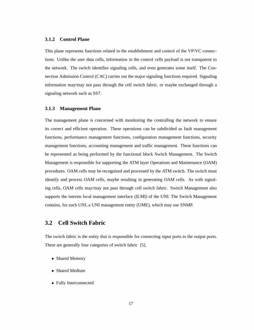
3.1.2 Control Plane
This plane represents functions related to the establishment and control of the VP/VC connec-
tions. Unlike the user data cells, information in the control cells payload is not transparent to
the network. The switch identifies signaling cells, and even generates some itself. The Con-
nection Admission Control (CAC) carries out the major signaling functions required. Signaling
information may/may not pass through the cell switch fabric, or maybe exchanged through a
signaling network such as SS7.
3.1.3 Management Plane
The management plane is concerned with monitoring the controlling the network to ensure
its correct and efficient operation. These operations can be subdivided as fault management
functions, performance management functions, configuration management functions, security
management functions, accounting management and traffic management. These functions can
be represented as being performed by the functional block Switch Management. The Switch
Management is responsible for supporting the ATM layer Operations and Maintenance (OAM)
procedures. OAM cells may be recognized and processed by the ATM switch. The switch must
identify and process OAM cells, maybe resulting in generating OAM cells. As with signal-
ing cells, OAM cells may/may not pass through cell switch fabric. Switch Management also
supports the interim local management interface (ILMI) of the UNI. The Switch Management
contains, for each UNI, a UNI management entity (UME), which may use SNMP.
3.2 Cell Switch Fabric
The switch fabric is the entity that is responsible for connecting input ports to the output ports.
There are generally four categories of switch fabric [5].
� Shared Memory
� Shared Medium
� Fully Interconnected
17

� Space Division
One of the important considerations while designing switching fabrics is the point at which
queues are built up. There can be two places - cells could be queued at the input ports, or at the
output ports.
� Input QueuingIn an input queued architecture, buffers exist at the input ports, while the
output ports have no buffers. When more than one cell destined to the same output port
arrives at a port p, a queue is formed. All subsequent cells are blocked at the input queue,
until the fabric can resolve both the cells. This leads to underutilization of the bandwidth.
Input queues are not desirable, for this reason.
� Output QueuingBuffers at the output ports queue cells destined for that port. Here, the
fabric needs to be non-blocking, otherwise if two cells destined for a single output port
cannot find unique paths to the port, one of them will be dropped. However, since output
queues lead to fuller utilization of bandwidth, they are the preferred form of queuing.
Assuming that the switch has an equal number (N) of input and output ports, the four cate-
gories are briefly described in the following sections.
3.2.1 Shared Memory Fabrics
Here all incoming cells are converted from serial to parallel form, and written sequentially to
a dual port RAM. A memory controller decides the order in which cells are read out of the
memory, based on the cell headers and internal routing information. This approach minimizes
cell loss under heavy load, but since the memory must run N times faster than the ports, it is not
scalable (Fig 3.1).
3.2.2 Shared Medium Fabrics
Cells are routed through a shared medium, like a Time Division Multiplexed bus (Fig 3.2). The
arriving cells are broadcast on the bus in a round robin fashion, and the output ports filter the
addresses, and accept cells bound for them. The problem with this approach is that the output
ports and the buses need to be C times the port speed, where C is the cell arrival rate in cells/s.
The popular ForeRunner ASX-100 from Fore Systems is based on this technique.
18

S/P
S/P
Memory Controller
P/S
P/S
Dual Ported
RAM
Input PortsOutput Ports
S/P Serial to Parallel P/S Parallel to Serial
0
N -1
0
N - 1
Figure 3.1: Basic structure of a shared memory switch [6]
P/SS/P
Buffer
Buffer
S/P Serial to Parallel P/S Parallel to Serial
Filter
Filter P/S
s
u
B
M
D
TS/P
0
N - 1
0
N - 1
Figure 3.2: Basic structure of a shared medium switch [5]
19

3.2.3 Fully Interconnected Fabrics
Here, independent paths exist between each of the input and output ports. Buffers at the output
port queue cells from each of the input ports. This approach is evidently ideal as far as traffic
management within the fabric is concerned, but is not scalable due to the quadratic increase in
the interconnections and output buffers (Fig 3.3).
0
1
N - 1
0 N - 1Output Ports
MUX
2
Input Ports
Buffers
MUX
Figure 3.3: Basic structure of a fully interconnected switch [5]
3.2.4 Space Division Fabrics
Switches that have interconnection networks that physically interconnect any of the N input
ports to any of the N output ports are called space division. These usually consists of tree like
formation of switching elements that physically connect on of their inputs to one of their outputs
(Fig 3.4). These switches usually require input queuing, and need complicated techniques to
overcome the inherent disadvantage of the queuing scheme [5], [7].
20

Switching
Element
Control Bit
AB
P
Q
0
1
B - Q
A - P
B - P
A - Q
Control Connection
Switching Table:
4x4 Banyan Network
Figure 3.4: 4x4 Banyan network and single element (Space Division Fabric)
3.3 Software Switching
Switches are usually built using custom hardware, since they are highly parallel and speed inten-
sive applications. However, modeling and testing of new and unproven aspects of the protocol
can be done on software test beds before full fledged investment into the hardware is made.
Software switches usually are a link between network simulations and hardware implementa-
tion of new protocols. If the required bandwidth of the network is small enough, a software
switch might be useful as an actual switching element. The following sub-sections describe the
integral components of a software switch as implemented for this project.
3.3.1 Switch Structure
As Fig 3.5 shows, the software switch designed has a fully interconnected fabric (section 3.2.3),
a control layer and minimal management. The switch can support up to 16 serial ports, each
of which is controlled by the ATMSL driver running Narrowband ATM., with speeds of up to
115 kbps per port. The switch also has a However, these are theoretical limits. Practically, on a
Pentium Pro based PC, 4 ports running at 19.2 kbps were tested. The main constituents of the
NATM switch are
� The switch is built on a PC platform, running Linux. Networking support on Linux exists
21

in the form of the BSD socket interface (section 2.4.1). The Linux ATM driver is patched
in to provide ATM Network and Link Layer support.
� The MicroSwitch driver, which implements a fully connected switch fabric is installed
for physical cell switching.
� The Narrowband ATM driver (NATM driver) which uses the serial port to transport Nar-
rowband ATM cells is installed.
� The Cyclades multiport card is used obtain series of low speed (up to 115 kbps) ports
fanning off a single hardware interrupt (section 2.4.4).
� A standard ATM Network Interface Card (NIC) is installed to obtain a fiber channel to
conventional ATM switches.
� Q.Port, a user level signaling application, that implements both host and switch Call
Control, is installed. A new interface between Q.Port and the underlying MicroSwitch
driver is written.
Some of these items are self evident. Salient features of the rest are described below.
3.3.2 The NATM Driver
The Narrowband ATM device driver, adapts a serial port to handle Narrowband ATM traffic
[11]. It is an implementation of the bottom half of the ATM Driver under Linux. It interfaces
with the Linux ATM Driver on one end, and the serial port on the other. It contains a round robin
scheduler which looks at the various open VCs and schedules data according to a preset priority
scheme. Real time (voice) traffic is given priority over data traffic. The scheduler is followed
by a Segmentation and Reassembly layer, to handle the various ATM Adaptation Layer types
as defined by the ATM Forum. The SAR layer queues fully formed ATM cells to the port in the
transmit direction, and fully assembled PDUs to the ATM interface in the receive direction. The
cells pass through an (optional) FEC module that adds the error correction to the cell, and the
bytes are then placed at the serial port. The interface to the serial port is modular. In the case
of the NATM switch, the serial interface is replaced with an interface to the Cyclades Multiport
card. The NATM driver registers itself with the ATM driver for each of the active ports below
22

E
R
K
E
R
N
E
L
U
S
Fabric
InterfaceOperating System Interface
Switch Call Controller
MicroSwitch
Driver
N
T
M
N
A
T
M
E
N
I
A
Cyclades Driver
N
A
T
M
data channels
Low Level Drivers
(SVCs)
PHYSICAL
LAYERSerial Ports (upto 155 kbps) 155 Mbps
Fibre Channel
Switch Signalling Application (Q.Port)
(PVCs)
ATM DriverLinux
signalling channels
Figure 3.5: The NATM Switch - Block Structure
23

that it is configured to handle. It instantiates local data structures for each of the ports, which
contain data to be transmitted and data received on that port. It wakes up the appropriate port
on multiport cards on switches (the default serial port on hosts), each time there is data to be
transmitted. The receive section is woken up by the port when data arrives.
3.3.3 The MicroSwitch Driver
The MicroSwitch driver is a simple cell level switching driver that is implemented for Linux.
It has an ioctl based interface, which can be used to connect and disconnect a VC on a port to
another VC on a different port. The connection is bidirectional. Cells arriving on either VC are
then dequeued, and queued on the outgoing queue of the complimentary VC. The driver does
rudimentary traffic management by blindly dropping cells if any of the destination queues be-
come too long. The switching is cell based in the sense that no SAR functions are implemented
in the driver and all the cells are treated as raw ATM data (AAL0).
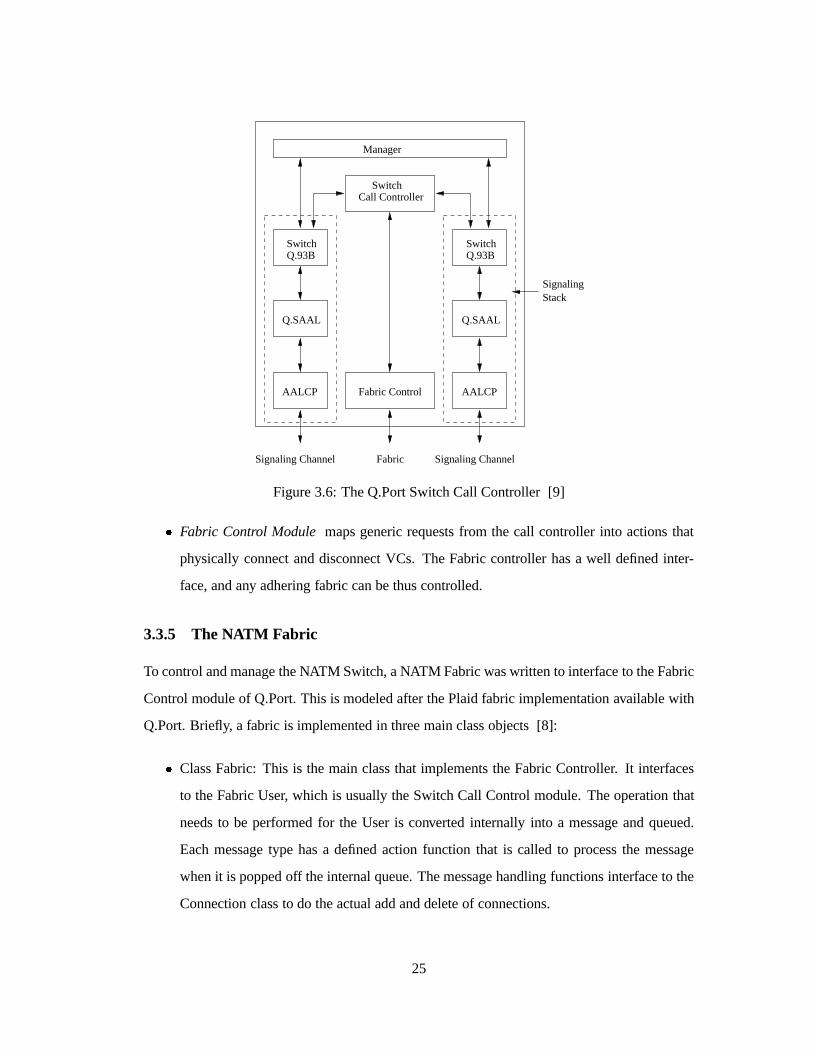
3.3.4 Q.Port
Q.Port [9] implements signaling stacks on a configurable number of ports. It provides both
UNI and IISP stacks, and a fabric controller. There are a few standard fabrics supported by
the application, however a well defined fabric interface allows one to implement custom fabric
interfaces for controlling non-standard switches(Fig 3.6). The main parts are
� Switch Call Control coordinates the various protocol entities supporting calling party
with one or more entities supporting called party and/or the next switch in the path in
creating a call. It determines routes, and controls the fabric interface according to call
setup and tear down requirements.
� Switch Signaling StackGrouping is built on each port, and can be either a UNI or IISP
stack. It helps establish, maintain and release SVC. It consists of three modules: a net-
work side implementation of the ATM Forum Q.2931 signaling protocol (also called
Q.93B), an implementation of Q.2130 data link protocol (Q.SAAL) and an AAL5 wrap-
per (AALCP).
24
AALCP AALCP
SwitchCall Controller
Fabric Control
Q.93BSwitch
Q.SAAL
SwitchQ.93B
Q.SAAL
Manager
Fabric Signaling ChannelSignaling Channel
SignalingStack
Figure 3.6: The Q.Port Switch Call Controller [9]
� Fabric Control Module maps generic requests from the call controller into actions that
physically connect and disconnect VCs. The Fabric controller has a well defined inter-
face, and any adhering fabric can be thus controlled.
3.3.5 The NATM Fabric
To control and manage the NATM Switch, a NATM Fabric was written to interface to the Fabric
Control module of Q.Port. This is modeled after the Plaid fabric implementation available with
Q.Port. Briefly, a fabric is implemented in three main class objects [8]:
� Class Fabric: This is the main class that implements the Fabric Controller. It interfaces
to the Fabric User, which is usually the Switch Call Control module. The operation that
needs to be performed for the User is converted internally into a message and queued.
Each message type has a defined action function that is called to process the message
when it is popped off the internal queue. The message handling functions interface to the
Connection class to do the actual add and delete of connections.
25

Call Reserve
Connect
Disconnect
ReserveAck
ConnectAck
DisconnectAck
Reserve
Negotiate
Establish
Connect
Disconnect
Connect
Disconnect
ioctl Connect
ioctl DisconnectMicroSwitch
(implied)
Driver
Connection
Fabric
Port (Left) Port (Right)
(Call Controller)Fabric User
(implied)
Figure 3.7: NATM Fabric and interactions
� Class Connection: This class maintains a connection record for management of the con-
nection. Each connection requests instantiates a new connection class object. The Fabric
interacts with this class to first reserve resources. This usually entails allocating data
structures for the connection, and selecting the VPI/VCI numbers on both the ports (the
left and right) that need the connection. After reserving the resources, the Fabric attempts
to negotiate bandwidth and establish the connection. The connection record contains all
the required data for managing the connection. It interfaces with the Port class to actually
establish the connection.
� Class Port: The Port class is instantiated by the Fabric for each of the ports that the
Fabric has been configured for. A configuration file is used by the Fabric to determine the
details for each of the ports, including the status of the port, the number of VPI and VCI
connections possible, the line rate etc.
The Connection object instantiated for each new call invokes the connect function on the left
and right Port objects to make the connection. The ioctl calls to the MicroSwitch driver are im-
plemented in the Port class. However, the design of the MicroSwitch driver is such that a single
26

connect call is sufficient to connect both the left and the right ports, so the NATM Connection
class regularly only calls the left port to connect to the right port. Similarly Connection calls
the disconnect function only for the left port, and the MicroSwitch driver then disconnects both
ports (Fig 3.7). Bandwidth negotiation is currently not supported since the higher layer adap-
tive networking modules allocated are involved in actively adapting the application bandwidth
requirement according to traffic conditions. Each connection is allocated the full bandwidth of
the channel. By the same token, bandwidth renegotiation is not supported.
3.4 Signaling on the End System
Signaling on the end system is performed by a set of daemons that are part of the ATM driver
for Linux. There are essentially three important signaling daemons.
3.4.1 ATMSIGD
Atmsigd is the UNI signaling daemon for the Linux ATM [10]. It implements the UNI 3.1
signaling stack for a single ATM interface on the host (Fig 3.8). The signaling daemon imple-
NetworkKernel
Internal Signaling Protcol
UNI signaling (Q,2931)
ApplicationSignaling
deamon
Figure 3.8: Linux ATM Signaling
ments the UNI signaling complexity as part of user space, while a simple protocol to support
ATM signaling resides in the kernel. The user process communicates with the kernel using a
simple Internal Signaling Protocol, which relies on the well ordered nature of the system to
manage the signaling. The ISP has been modified to accommodate a new daemon to handle the
AAL2 Negotiation. The ISP uses synchronous communication based on BSD sockets.
Linux ATM ISP
A set of simple messages characterize the ISP. They are listed below, and briefly described.
27

� as connect This message is sent by the kernel to request establishment of an out-bound
connection (possibly due to a user application connect request). The daemon responds
with anas okay or as error , as the case may be. This sequence usually completes the
connection setup process when the user does a ’connect’.
� as bind This message is sent by the kernel, usually as a result of a user application
performing a bind system call, to verify the local address chosen by the application. There
are no state changes related to this message.
� as listen The kernel send this message to the daemon to register a ATM Service Ac-
cess Point (SAP), when a user process does a listen system call. The daemon, as usual,
responds with aas okay or anas error .
� as indicate The daemon sends the kernel this message when it receives an incoming call
indication for a corresponding SAP. The kernel responds either with anas accept if a
user is awaiting the connection (blocking on the accept system call), or anas reject .
� as accept The kernel sends this message, as described, in response to theas indicate
message.
� as reject The kernel sends this message, as described, in response to theas indicate
message.
� as okay used in either direction, this message is a generic acknowledgment, and is used
to exchange parameters between the kernel and the daemon.
� as error This message is used by the daemon to indicate an error while processing the
previous kernel message.
� as close This message can be used in three ways:
– Kernel to daemon: to indicate the normal closing of a connection by an application,
e.g. with a close system call.
– daemon to kernel: to indicate the normal closing of a connection by the remote party
– daemon to kernel: to indicate the abnormal closing of a connection, e.g. by the
network.
28

The kernel acknowledges anas close with exactly oneas close or as error message,
that the daemon uses to destroy all the connection information it has.
3.4.2 ILMID
Ilmid is the Interim Local Management Interface daemon that is used to manage the host status
and configuration, perform address registration and update at the switch. It uses existing SNMP
standard, and defines a new ATM UNI Management Information Base (MIB) to perform VC
status and management, operational measurement as required, diagnostics, etc [3].
3.4.3 ATMARPD and ATMARP
Atmarp is used to resolve IP addresses over an ATM subnet. The ATMARP requests and replies
are sent using AAL5. The ATMARP structure consists of an ARP Server, whose ATM address
is well known within the subnet. Hosts wanting to resolve IP addresses to their respective ATM
addresses send queries to the ARP server, which looks up it’s data base and responds with the
required address. The ARP server updates it’s data base when it receives ARP requests by
sending inverse ARP or InARPREQUEST to the originating host for each logical IP subnet
the server is configured to serve. In the event that the server is unable to find the corresponding
entry in it’s table, it returns an ARPNAK to the host.
The ARP client is responsible for contacting the ARP Server with it’s own IP address to
register itself. This usually happens at boot-up time. It is also responsible to initiate and main-
tain a VC to the ARP server, respond to ARP and InARP requests, and generate and transmit
ARP REQUEST when required by applications wishing to make connections.
29

Chapter 4
Protocols and Data Structures
4.1 ATM Adaptation Layer 2
AAL2 is an adaptation layer that is used to multiplex more than one constant low bit rate user
information stream on a single ATM virtual connection [12]. This AAL provides for bandwidth
efficient transmission of low-rate, short, and variable length packets in delay sensitive applica-
tions. In situations where multiple low Constant Bit Rate data streams need to be connected on
end systems, a lot of precious bandwidth is wasted in setting up conventional VCs for each of
the connections. Moreover, most network carriers charge on the basis of number of open Virtual
Connections, hence it is efficient both in terms of bandwidth and cost to multiplex as many of
these as possible on a single connection. In [12], we find a preliminary standard published
by the International Telecommunication Union (ITU-T), and although some portions require
further refinement, the standard is well threshed out.
4.1.1 General Framework of AAL2
The AAL type 2 is subdivided into the Common Part Sublayer (CPS) and Service Specific
Convergence Sublayer (SSCS) as shown in Fig 4.1 (a). Different SSCS protocols may be
defined to support specific AAL2 user services or groups of services. The SSCS may also be
null, providing merely for the required mapping between the CPS and higher layers. AAL2
provides the capabilities to transfer AAL-SDUs from one AAL-SAP to another through the
ATM network (Fig 4.1 (b)). Multiple AAL2 connections may utilize a single underlying ATM
30

connection. The multiplexing and de-multiplexing of connections occurs at the CPS.
CPS PDU Payload
ATM
CPS
CPS-SDU
SSCS-PDU
ATM Cell Payload
CPS Packet
ATM PDU (ATM Cell)
SSCS
STF
CPS-PH
SSCS SSCSTrailer *Header *
AAL-SDU* - optional
AAL-SAP
ATM-SAP
Header
CPS - PDU AAL Entity AAL Entity
A
A
L
A
T
M
Connection
Point to Point ATM
AAL SAPAAL SAP
(a) (b)
Figure 4.1: AAL2 Structure (a) Sections and Data Interfaces (b) Connection
CPS to ATM data interface
The CPS hands a 48 byte ATM payload to the ATM layer below it, a 1 bit ATM User to ATM
User (AUU) indication, and a loss priority (called the Submitted Loss Priority). SLP is used by
the ATM layer to set it’s own CLP bit. CPS also receives from the ATM layer a 48 byte SDU,
and a loss priority bit (called the Received Loss Priority). The RLP may differ from SLP in case
the network changed CLP along the way.
CPS to SSCS data interface
The CPS hands CPS-Interface data packets to the SSCS (1 to 64 bytes). The format and actual
length of the data are determined at setup time, as described later. The CPS also hands a 5 bit
User to User Indication to the SSCS. This is data used optionally by the SSCS entity to decide
the destination of the PDU. The CPS also receives the same two units from the SSCS entity.
31

4.1.2 The Common Part Sublayer
AAL2 CPS offers the following peer to peer operation:
� Data transfer of CPS-SDUs of up to 45 (default) or 64 bytes.
� Multiplexing and de-multiplexing of multiple AAL2 channels.
� Maintains the CPS-SDU sequence integrity on each AAL2 channel
� Unassured operation, i.e. lost CPS-SDUs are not retransmitted
� Bidirectional virtual channel connection, using the same VC number in either direction.
The VC can be permanent or switched.
The CPS interacts with both the management layer and the control layer. The control layer
establishes the VC as required. Switching at the channel level has not yet been defined.
Format and Encoding of CPS Packet
CPS INFO
CPS Packet
CPS Packet Header (CPS-PH) CPS Packet Payload (CPS-PP)
CID LI UUI HEC
Figure 4.2: AAL2 CPS Packet Format
A CPS Packet consists of a 3 byte Packet Header (CPS-PH), followed by up to 64 bytes
of Packet Payload (CPS-PP). CPS Packets are the data exchange mechanism between CPS and
SSCS. Fig 4.2 shows the field lengths and format.
� Channel Identifier (CID) value identifies the AAL2 channel user. The AAL2 channel is a
bidirectional-medium, and both directions use the same value of CID.
32
CID value use
0 not used
1 reserved for layer management peer-to-peer operations
2 ... 7 reserved
8 ... 255 identification of SSCS entity
� Length Indicator (LI) is a binary encoded value that corresponds to the length of the
payload of the CPS-Packet. The default maximum length is 45 bytes. It can be set to
a maximum of 64 bytes. The maximum channel length needs to be negotiated at setup
time. LI cannot exceed the maximum negotiated value. Each channel can individually
negotiate it’s maximum value. Maximum lengths between 45 and 64 are not allowed.
� User-to-User Indication (UUI) serves two specific purposes :
– To convey specific information to SSCS entities transparently through the CPS.
– To distinguish between the SSCS entities and Layer Management users of the CPS
The 5 bit UUI field is handed without change by CPS to the SSCS entity. It’s usage by
the SSCS entity is optional.
� Header Error Control (HEC) is the reminder (modulo 2) of the division, by generator
polynomialX5 +X2 +1, of the product ofX5 and the contents of the first 19 bits of the
CPS-PH. The receiver uses the HEC field to detect errors in the CPS-PH.
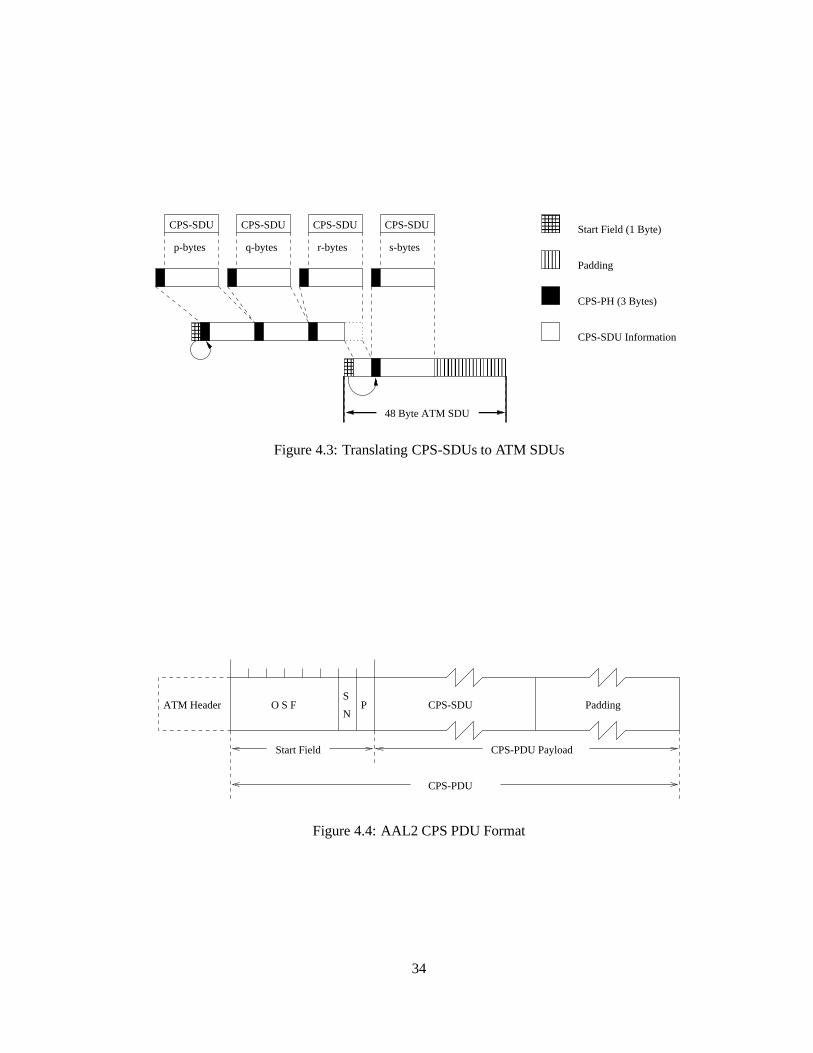
Format and Encoding of CPS-PDU
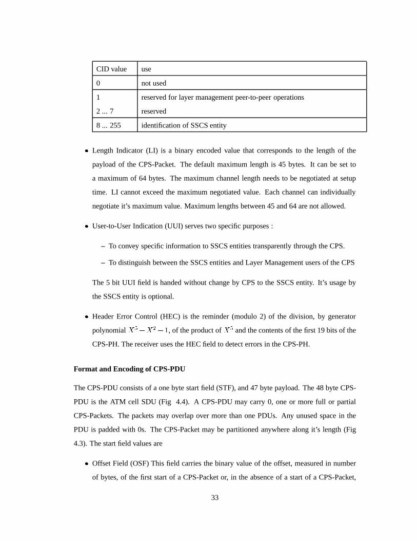
The CPS-PDU consists of a one byte start field (STF), and 47 byte payload. The 48 byte CPS-
PDU is the ATM cell SDU (Fig 4.4). A CPS-PDU may carry 0, one or more full or partial
CPS-Packets. The packets may overlap over more than one PDUs. Any unused space in the
PDU is padded with 0s. The CPS-Packet may be partitioned anywhere along it’s length (Fig
4.3). The start field values are
� Offset Field (OSF) This field carries the binary value of the offset, measured in number
of bytes, of the first start of a CPS-Packet or, in the absence of a start of a CPS-Packet,
33
48 Byte ATM SDU
���
����
���
������������������������������
������������������������������
CPS-SDU Information
��������
������������
CPS-SDU CPS-SDU CPS-SDU CPS-SDU
p-bytes s-bytesq-bytes r-bytes
Start Field (1 Byte)
Padding
CPS-PH (3 Bytes)
Figure 4.3: Translating CPS-SDUs to ATM SDUs
Padding
CPS-PDU
CPS-PDU PayloadStart Field
ATM Header O S FN
SP CPS-SDU
Figure 4.4: AAL2 CPS PDU Format
34

to the beginning of the PAD field. A value of 47 indicates that there are no CPS-Packet
starts in this PDU.
� Sequence Number (SN) This i bit field is a modulo 2 sequence number of the stream of
CPS-PDUs
� Parity (P) To detect errors in the STF, a 1 bit odd parity is set as the last bit of the STF.
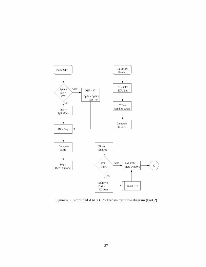
4.1.3 AAL2 CPS Procedure
The CPS consists of distinct transmission and receptions state machines that function indepen-
dent of each other. The transmission state machine needs to multiplex the various channels
into as few ATM SDUs as possible, while still maintaining the time requirements of the CBR
traffic, while the reception state machine needs to demultiplex channels that can be spread over
multiple ATM SDUs.
AAL2 Transmitter
The multiplexing function in the CPS to merge several different sized streams into a single
ATM SDU requires a method for scheduling these streams so that none of the streams suffer
any more than acceptable delays. The nature of traffic on AAL2 channels require a CPS SDU
to be transmitted within a certain time frame after it is generated. In algorithmic form, the CPS
transmitter has the following procedure (Figs 4.5, 4.6):
1. The CPS transmitter starts in the IDLE state. When a CPS PDU is passed to it, build the
CPS Packet Header, start TimerCU, build the STF.
2. If a previous part or whole CPS SDU is waiting for transmission, then append the current
SDU to the waiting ATM SDU for transmission.
3. If no data is waiting to be transmitted (State is IDLE), then start a new ATM SDU.
4. If the STF needs to be built, use the end of the waiting data as the start pointer in the STF.
5. If Data Queued< ATM SDU size, set state as PART, set the Part variable for future STF
calculations (if needed), wait for new CPS SDU. When the SDU arrives, jump to step 2.
35

B
More TXData?
Build STF
Append to oldATM SDU
Build STF
Build STF A
CPS-SDU
New CPSSDU?
Wait for SDU
NO
STARTState = IDLEBuild IDLEBuild IDLE
Part = 0Seq = 0Split = 0
STF STF
ATM SDUStart new
filled?
Queue ATM SDU for TX
Stop Timer
ATM SDU
State =IDLE?
NO
YES
YES
TIMER_CU
Start
HeaderBuild CPS
State = PART
YES
NOB
A
New CPSSDU?
Wait for SDU
STF
Built?
YES
NO
YES
NO
YES
C
Part = TXData
NO
Start
TIMER_CU
Figure 4.5: Simplified AAL2 CPS Transmitter Flow diagram (Part 1)
36
SN = Seq
Compute Parity
Seq = (Seq++)mod2
NO
Build STF
Split +Part >47 ?
YES
NO
OSF = Split+Part
LI = CPS
ComputePH CRC
Sending ChanCID =
SDU Len
Build CPSHeader
Timer Expired
STFBuilt?
Pad ATMSDU with 0’s
Split = 0Part =TX Data
Build STF
C
OSF = 47
Part - 47Split = Split +
YES
Figure 4.6: Simplified AAL2 CPS Transmitter Flow diagram (Part 2)
37

6. If the ATM SDU is filled, stop the TimerCU, queue it for transmission.
7. If data remains to be transmitted, start TimerCU, build the STF, jump to step 2.
8. Set State as IDLE, jump to step 1.
9. When the TimerCU expires, build an STF if none is built (using the start of the padding
as the start pointer in the STF), pad the remaining part of the ATM SDU with 0’s, jump
to step 6.
AAL2 Receiver
The Reception state machine is simpler because the time dependence of the channels is taken
care of while transmitting. However, packet discard is an important step in the receiver, since
entire ATM SDUs cannot be discarded if any one channel has errors (Figs 4.7, 4.8).
1. The CPS receiver starts in IDLE State.
2. Wait for a new ATM SDU. When a new ATM SDU arrives, obtain the offset value, check
the STF parity.
3. Discard erroneous SDUs, and any waiting CPS SDU. If the offset is not zero, append data
up to the offset from the ATM SDU to the waiting CPS SDU.
4. If the CPS SDU is> maximum data size for the channel, discard CPS SDU.
5. If more data remains in the ATM SDU, start a new CPS SDU, populate channel number
field. If the channel number is 0, the rest of the ATM SDU is a pad, discard the ATM
SDU, jump to step 1. If no more data, jump to step 1.
6. If data remains in the ATM SDU, find the length of the channel. If length is greater than
Max channel length, discard the CPS SDU. Jump to step 4.
7. If data remains in the ATM SDU, get the HEC, perform Header Error Correction. If error
detected, discard CPS PDU, jump to step 5.
8. If data remaining in the ATM SDU>= length of channel, transfer channel information
to the CPS SDU, hand the SDU to the higher layer, jump to step 5.
38

START
Data_remState = PART
CPS SDU gets
channel ?Is ch_len <=
channel ?Is ch_len <=
YES
Wait for newATM SDU
Is State =PART?
InterpretSTF
Is Offset =0 ?
InterpretCPS Header
Is ch_len <Data_rem?
Transfer Datato CPS SDUData_rem -=
Is Offset =
Set State =IDLE
0 ? present?Is HECpresent ?
A
B
B
B
Get ch_len Get HEC fromCPS Header
A
Transfer Datato CPS SDU
Data_rem -=ch_len+CPS_PH
A
C
0 ?
Is Data_rem = 0 ?
Release CPSSDU
Get ch_len
from CPS Hdr
ch_len+CPS_PH
D
D
0?
B
YES
YES YES
YES YES
YESYES
YES
NO NO
NO NO
NONO
NONO
C
NO
NO YES
YES
NO
Is Data_rem = Is Data_rem =
from CPS Hdr
Is ch_len
Figure 4.7: Simplified AAL2 CPS Receiver Flow diagram (Part 1)
39

Inpret CPSHeader
D
Get ch_id fromCPS Header
Is ch_id= 0 ?
Discard restof ATM SDU
Get ch_lenfrom CPS Hdr
Get HEC fromCPS Header
Release CPSSDU
Free CPS Data SKB
Data_rem -=ch_len
set offset = 0set ch_len = 0
C
Get Offsetfrom STF
InterpretSTF
Get Seq Numfrom STF
Do Paritycheck on STF
Is Paritycorrect?
ReleaseCPS SDU
Figure 4.8: Simplified AAL2 CPS Receiver Flow diagram (Part 2)
9. If no more data remains, and new channel number exists, jump to step 1.
10. If data remaining in the ATM SDU< length, transfer remaining data from ATM SDU to
CPS SDU, set state = PART, jump to step 2.
4.1.4 AAL2 Negotiation Protocol (ANP)
The ATM signaling protocol as defined in UNI 3.1 does not cater for setting up and tearing down
individual channels across a switched network. Further, the each channel is an entity by itself,
requiring a complete negotiation process like the setup of SVCs over a switched network. In this
event, a separate negotiation protocol is required that can manage channels on individual VCs.
The following aspects must be considered while designing and implementing the negotiation
protocol:
� Transparency: The negotiation protocol must be implemented such that the setting up and
deleting of individual channels is transparent to the switched virtual network. Since no
signaling support is available on any of the component systems, channel setup must work
within the framework of the existing protocol.
40

� User Interface: The user interface of the negotiation protocol must be kept as close to the
standard Unix socket interface (as described in Section 2.4.1) as possible. User interfaces
need to be available only on the end systems that have low level support for AAL2.
� Bandwidth Negotiation: The protocol must support at least some rudimentary form of
bandwidth negotiation, so that channels can be guaranteed the bit rate they started out
with. The ANP must restrict additional channels until it can allocate the requested band-
width.
� Channel numbers: There are two ways that the ANP can allocate channel numbers - the
simple method is to have well known channel numbers on both ends, so that processes
setup listening sockets with channel numbers and lengths, and arriving connections are
accepted by the ANP if a process is listening on that channel number. However, a more
generic method would be to do a LANE like implementation, where ANP clients enquire
an ANP Server, and get channel numbers allocated.
ANP Functionality
The ANP is implemented in the form of a daemon that runs on the end systems that need to
setup AAL2 channels (Fig 4.9). The following points outline the functionality of the ANP:
CBRApp
AAL2CBRApp
AAL2CBRApp
AAL2CBRApp
AAL2
End System B
ANP
Daemon
Signalling
Daemon DaemonDaemon
Signalling ANP
NetworkATM
Switched
AAL2 Channel
ANP peer to peer communication
Switched Virtual Circuit
X X
YY
End System A
Figure 4.9: AAL2 Negotiation Protocol Peer to Peer communication architecture
41

� Channel SetupEach time a process wants to setup a new channel, the ANP daemon is
contacted. The daemon can either allocate channel numbers, as in the case of query based
channel number selection, or is provided a channel number by the process. It is then the
ANP’s responsibility to contact it’s peer on the called party, and negotiate the channel
setup.
� Bandwidth NegotiationThe ANP daemon also watches upon the allocated bandwidth on
the end system. The total bandwidth allocated cannot exceed the practical limit of the
link rate. This is true for both the transmit and the receive sides.
� Data TransferThe ANP provides a transparent path for the data transfer on a channel.
� Channel ReleaseWhen the party at either end wishes to release the connection, the ANP
at that end signifies it’s peer of an end of transmission so that both ends can release the
resources dedicated to the channel.
4.2 Data Structures
There are some data structures in the kernel critical to the functioning of both the low level
driver and the ANP daemon. These are detailed below, with the functionality of some of their
more important fields highlighted.
4.2.1 Socket Structure
The socket structure is created and maintained for each socket opened by any process under
Linux. This needs to be a small and cohesive structure since it is used extensively throughout
the kernel and by any application wanting to perform any form of communication. Important
fields:
� type: The communication protocol type, namely whether it is a stream or datagram
protocol type.
� state: Defines the connection state of the socket, starts with unconnected.
42

� ops: Pointer to a structure of functions pointers that perform the various operations on
the socket, like read, write, close etc. This pointer is set by the driver of the protocol type
of the socket.
� data: Pointer to the data needed by the protocol. In the case of ATM, the data pointer
points to the VCC structure associated with the socket (section 4.2.3).
4.2.2 Data Buffers (SKBs)
The socket interface uses a special data structure to store and manipulate Protocol Data Units, or
PDUs, called the Socket Buffer, or the SKB. SKBs are double linked list structure elements, de-
signed so that they can be easily queued to lists, removed and recycled in these lists. Although
they were designed initially to handle Internet Protocol (IP) data units, they have since been
extensively, and perhaps haphazardly modified to handle other PDUs. The ATM driver adds ex-
tensive data elements to the SKBs, and these are set and used within the ATM driver. Each SKB
has pointers to the socket it is associated with, a huge amount of protocol specific information
(the VCC structure in the case of ATM), pointers to the data buffer space, and pointers to the
SKBs on either side of it. The important fields are
� prev andnext: These pointers are used to traverse the linked list of SKBs
� sk: pointer to the socket owning this SKB.
� data: points to the start of the data.
� tail: points to the end of the data.
� size: andtruesize integers containing the length of the data in the SKB.
� vcc: pointer to the ATM protocol information.
� dev: pointer to the physical device that the SKB arrived on or is destined to.
4.2.3 Virtual Channel Structure (VCC)
Each new application that opens an ATM socket is assigned a VCC structure. Traditionally,
each ATM socket can potentially be connected to a new virtual channel, so each VCC structure
43
essentially points to all the data needed to setup, maintain and modify a virtual connection.
Important fields:
� aal , vci andvpi are self explanatory.
� qos: a data structure that contains the quality of service negotiated for the connection.
� local andremote: address structures that contain the ATM address (section 2.2.3) in
any supported format.
� sleep: the wait queue structure pointer that is used to put the current task to sleep in the
event that it waits for an event, like data to arrive on a connection.
� tx quota,rx quota,tx inuse andrx inuse: are used to monitor the data pending in either
the receive queues or the transmit queues. The quotas are the upper limit to the buffer
space available for pending data. Once the quota is met, the connection will not accept
any further data until some of the pending data is disposed of.
� recvq: is the SKB queue containing the SKBs that have arrived on this connection.
� push: is a pointer to the function that the low level drivers can use to hand the data to the
higher layer.
44

Chapter 5
Implementation and Results
This chapter deals with the implementation of the low level AAL2 support under Linux ATM for
the ATMSL driver, and the implementation of the ANP daemon on the same platform. The low
level driver is heavily dependent on the ATMSL driver architecture [11], and the Linux ATM
driver [4]. The ANP daemon interacts only marginally with the ATMSL driver. However, it
interfaces to the section of the Linux ATM driver within the kernel to trap AAL2 setup messages
and to setup communication channels to peer ANP daemon on demand.
The latter half of the chapter describes some of the results obtained while testing the AAL2
implementation. The AAL2 is compared with AAL5 under similar conditions, and the results
obtained indicate the superiority of AAL2 over AAL5 for small CBR data packets.
5.1 Implementation
5.1.1 AAL2 Driver Support Implementation
Some of the data structures that are used by the kernel at various levels were modified to support
AAL2. The main fields that were added were:
� Socketdata structure
– atm aal2 chan - used to store the AAL2 channel number associated with the socket
� ATM VCC data structure
45
– chan len : an array of the lengths of all channels that can be opened in a VCC. A
chanlen entry of0 indicates an unopened channel.
– aal2 state: used to block a VCC so that a degree of atomicity of operations can be
guaranteed.
– curr channel: The channel number that is currently being processed.
– ch queue: Pointer to a new structure of typechannelqueue, which contains a
wait queue array, with an entry for each channel, and an SKB list array, with an
entry for each channel. These separate queues are needed, since at any given time,
more than one channel could be awaiting data from one connection, and each needs
to be blocked (put tosleep) on a different waitqueue. Similarly, each channel
needs a separate SKB list to dequeue it’s SKBs.
– aal2 sock: A back pointer to the socket that owns the VCC. This could point to any
one of the sockets that have channels open to the VCC.
The modifications needed to support AAL2 were distributed to the various sections of ATM
under Linux as follows:
Modifications for Data Transmission
� High Level ATM driver
– The High Level ATM driver was modified to handle AAL2 as a type of ATM Adap-
tation Layer.
– The Transmit section of the driver was modified to add a 3 byte CPS Packet Header
according to the information available (sec 4.1.2).
– The transmit section is also modified to put an AAL2 channel process to sleep on
it’s appropriate waitqueue entry, as detailed above.
� ATMSL driver
– The multiplexing of CPS SDUs into ATM SDUs is handled in the low level driver. It
also implements a per channel timeout (TimerCU) according to the CPS procedure
specifications in section 4.1.3. The STF for the ATM SDU is built here (sec 4.1.2),
46
and the completed ATM SDU is queued for transmission as in the case of other
AALs.
– A procedure to handle the timeout of the AAL2 channel is implemented, with pro-
vision to pad the remaining ATM SDU with0.
Modifications for Data Reception
� High Level ATM driver
– The Receive procedure is modified to wake up the correct sleeping channel upon
the arrival of data for a particular channel on the connection, and to queue the data
SKB to the appropriate SKB queue for that channel.
– It is modified to distinguish between dequeuing SKB data for an AAL2 channel
versus the regular case, so that when a channel is trying to read data, the block
(sleep) process and the data read (skbdequeue) processes target the appropriate
pointers.
� ATMSL driver
– The driver is modified to demultiplex the AAL2 streams in the ATM SDU. The CPS
SDU Packet Header is interpreted to obtain channel, length and HEC information,
according to section 4.1.3. Unfinished channels are stored until the next ATM SDU
arrives. Finished channels are handed to the higher layer.
5.1.2 AAL2 Negotiation Protocol Implementation
The ANP was implemented as a transparent Peer to Peer communication protocol that used
standard SVCs to communicate over switched ATM networks between peers. Each end system
initiates an ANP Daemon to facilitate AAL2 communication. The salient features of the daemon
are:
� It achieves transparency across a switched network by faking an AAL2 VC as an AAL5
VC. ANP daemons setup unique AAL5 SAPs with the ATM signaling stack on end sys-
tems. Connections to these SAPs are nominally AAL5, but the low level drivers treat
47
them like AAL2 connections. Thus, only the end systems need be AAL2 aware, and VC
setup and tear down is UNI compliant.
� It uses in-band signaling to setup and tear down new channels within the VC. All traffic
on the VC is routed via the local ANP daemon, and all data on the signaling channel
(channel 7 in this case) is interpreted by the daemon. The other channels are forwarded
to their respective users.
� It blocks and unblocks the user processes during channel setup.
� Each user process is allowed to request a certain bandwidth from the daemon (a default
bandwidth is assumed if no request is made) during setup time. If the link cannot support
the bandwidth due to existing channels, the daemon refuses the connection.
� A user process registers with the daemon, informing the channel it is waiting upon, and
what the maximum length of this channel is expected to be. The daemon blocks the
listening user process until it receives an appropriate setup message from a remote peer.
� When a process decides to close a channel, the ANP daemon sends a channel delete
message to it’s peer. The peer daemon then releases the corresponding channel resources,
and informs the process that is transferring data at it’s end regarding the release of the
channel.
� When a VC is torn down, for example due to a network error, the daemon informs all
processes with channels open on that VC regarding the shutting down of the connection.
� A part of the ANP daemon is implemented in kernel (as an addition to the Linux ATM
driver). The ANP thus consists of two communication protocols -
– Peer to Peer Signaling Protocol, Used to negotiate channel setup between peers.
All messages can originate on any of the daemon instantiations.
– ANP Internal Signaling ProtocolUsed to communicate between the kernel and the
daemon sections of the ANP. The daemon is the master, and the communication is
well ordered and predictable.
48
ANP Peer to Peer Signaling Message Format
Peer to peer communication between ANP daemons is facilitated using fixed length messages
on the signaling channel. The low level driver treats these messages in a fashion similar to
all other channels. However, these messages are filtered by the ANP daemon, and it takes the
appropriate action. Currently, the message format is small, and the signaling protocol is simple.
This may need to be extended in order make it robust enough to handle real world situations.
� type the message type can be one of
– ch setup : New Channel setup request.
– ch delete: Delete existing channel request.
– ch accept: Accept new channel setup.
– ch reject : Reject new channel setup.
– ch accept conf : Confirm channel setup accept.
– ch close: Close connection (and all channels) request.
� cause the cause for the message (usually for the reject) can be
– ca bad ch : Bad channel number (either the channel number is beyond bounds (sec
4.1.2), or no process awaits this channel).
– ca bad len : Bad channel length (either the length is out of bounds (sec 4.1.2), or
the waiting process specifies a different maximum length).
– ca limit : Bandwidth of the receiver is currently full.
– ca bad msg: Message type not understood.
– ca none: No cause
� chNum The channel number for which the message is sent.
� chLen The length of the channel in question.
� bandwidth The bandwidth that the application has requested, or the bandwidth of the
channel to be deleted. This is used to negotiate bandwidth at setup time.
49
ANP Peer to Peer Protocol
� Channel SetupWhen the ANP needs to negotiate a channel setup, the daemon on the
calling end system sends a message of typesetup on the signaling channel to it’s peer,
with the requested channel number in thechNumfield, the requested channel length in
thechLen field, and the maximum required bandwidth in thebandwidthfield. If the peer
has a waiting channel with the requested channel number and a matching channel length,
and can accommodate the requested bandwidth it replies with an message of typeaccept
, with thechNum field containing the negotiated channel number. If these conditions are
not met, the peer returns a message of typereject , with the cause field populated with the
reason for the reject. Upon receiving an accept, the initiating channel sends a message of
typeaccept conf .
� Channel DeleteWhen the ANP needs to delete a channel, the daemon on the initiating
system sends a message of typedelete , with the channel number to be deleted, the
channel length, and the bandwidth of the deleted channel encoded. The peer system
updates it’s status, releases the channel, and need not respond to this message.
ANP Internal Signaling Protocol
The ANP daemon is integrated into the kernel by having a small section in the kernel, which is
used to way-lay AAL2 socket setup and connect messages. These are picked up and interpreted,
and a corresponding message is composed and sent to the user space daemon. This requires an
Internal Signaling Protocol, across the kernel boundary, with it’s own message format.
ANP ISP Message Format
The ANP ISP passes fixed length message from and to the kernel using a socket that is desig-
nated the default kernel communication socket. The message format is:
� type Indicates the message type (sec 5.1.2)
� vcc Used to transfer VCC pointer information. Although the VCC pointer is not valid
outside the kernel, the daemon uses it for indexing.
50

� chNum, chLenChannel number and length fields - valid in both directions.
� anp fd Since only file descriptors are valid outside the kernel, the daemon passes new
file descriptors to the kernel so that the VCC can be dereferenced for it’s purposes.
� svc The address, inE:164 format (sec 2.2.3), of the remote party. Used by the kernel to
inform the daemon of the party that the application wants to connect to.
� blli The low level information that can be used to make an AAL2 SAP uniquely identify
itself to the daemon. It is not currently supported.
ANP ISP Message Type And Direction
The ANP ISP messages are usually significant in only one direction, although this is not always
the case. Also, not all fields are significant in all the messages (K denotes the kernel, D denotes
the daemon).
� anp accept K �! D. This is to indicate that a process has setup an AAL2 socket, and
listening on a particular channel for messages of a particular length.
� anp listen K �! D. This message is sent before the accept, and is currently ignored.
� anp indicate K �! D. To indicate that a remote peer is trying to connect to the AAL2
SAP.
� anp wakeup D �! K. To wakeup a sleeping process when a channel that it has been
listening in is successfully negotiated.
� anp connect K �!D. To indicate that a local process want to open a channel to a remote
end system
� anp reject D �! K. To reject a connection request by a local process, for example due
to insufficient bandwidth.
� anp okay D ! K. Generic acknowledgment.
51

� anp delete D ! K. Message to release a channel. The kernel sends it to the daemon
when a local process wishes to terminate a channel, the daemon sends it to the kernel
when a remote process closes a channel.
5.1.3 ANP Procedure
aal2_socketconnect
Application
unblock
block setup VC
block
unblock
SignallingANP
setup SVC
block
aal2_socket
unblock
ATM NETWORK
Signalling ANP
channel data transfer
accept channel
negotiate channel
call accept
call proceeding call setup
call accept
accept (channel)
Application
Figure 5.1: Initial channel setup to remote end system
The ANP processes requests, generates messages blocks and unblocks applications on de-
mand.
Connect Procedure
� The ANP registers a unique SAP with the ATM signaling daemons, using theblli and
bhli subfields of the SVC address.
52

aal2_socketconnect
accept channel
block
SignallingANP
block
aal2_socket
ATM NETWORK
Signalling ANP
accept (channel)
Application Application
unblock
unblock
channel data transfer
negotiate channel
Figure 5.2: Subsequent channel setup to same end system
� When an application desires to open a new AAL2 channel, it performs aconnect sys-
tem call on an AAL2 socket. The kernel first blocks the application, then sends an
anp connect message to the ANP daemon.
� The daemon checks it’s internal database to see if any channels have been opened to the
called party previously. If this is the first channel, it opens an AAL5 SVC to the peer
ANP daemon, using theblli andbhli (Fig 5.1). It then negotiates the channel according
to the Peer to Peer protocol.
� If the setup requested is not the first to remote host, the daemon looks up the file descriptor
to the remote host, and negotiates a new channel setup (Fig 5.2).
� If the setup is successful, the daemon returns ananp okay message, along with the
file descriptor to the new/existing connection. The kernel then changes the VCC pointer
of the AAL2 socket to point to the VCC pointer of the SVC connection to the host,
dereferenced from the file descriptor, and proceeds with a low level connect. It then
unblocks the application.
� If the setup is unsuccessful, the daemon return ananp error message. The kernel un-
53
blocks the application with an error.
� The process is now free to exchange data, and subsequently close the connection.
Listen Procedure
� When an application wants to listen to an as yet unopened channel, it does thelisten and
accept system calls on an AAL2 socket. The kernel blocks the application, and sends an
anp accept message to the daemon.
� The daemon adds the parameters of the new listening channel to it’s queue of waiting
channels.
� When a remote host desires to open a new AAL2 VC (an AAL5 VC setup to the AAL2
SAP), the kernel sends ananp indicate message to the daemon. The daemon does an
accept , and the connection proceeds according to the traditional BSD socket protocol.
Once the connection is established, the ANP daemons communicate over this VC using
channel 7 as the signaling channel.
� If the daemon receives ach setup message over the signaling channel, it checks to see
if a channel with the required parameters is waiting for a connection. If yes, it checks to
see if it can handle the bandwidth.
� If the setup conditions are met, the daemon sends ananp wakeup message to the kernel,
and ach accept message to it’s peer. It then deletes the waiting channel from it’s list.
The kernel transfers the VCC pointer of the blocked application to the VCC pointer of
the SVC, and unblocks it.
� If the setup conditions are not met, the daemon simply sends a reject to it’s peer.
� The application woken up is now free to exchange data, and subsequently close the con-
nection.
Channel Delete Procedure
� When a application closes a channel (releases a socket), the kernel sends ananp delete
message to the daemon. The daemon then sends ach delete message to it’s peer and
54
releases the bandwidth and channel number occupied by the channel.
� When the daemon receives a channel delete message on the signaling channel, it releases
the bandwidth and channel number occupied by the channel, and sends the kernel an
anp delete message.
� If the daemon receives ach delete message on an already deleted channel, it recognizes
that this is an echo of the message it sent previously (as a result of the peer sending a
delete message to it’s kernel), and does nothing.
5.2 User Interface
The user interface to setup, use and close AAL2 channels on compliant machines is as close to
the BSD Socket Interface as possible (sec 2.4.1). The socket is setup, connected and closed as
before. socket options are used to set the AAL2 specific features of the socket, like the channel
number, channel length etc. The following points list the socket interface for AAL2 channels.
Appendix B contains pseudo code that reflects the principles behind the user interface. The
user opens a socket using thesocket system call. The socket family is PFATMSVC, the AAL
type is ATM AAL2. Setting the qos is standard [4], except that the sdu size in either direction
must be the same (usually set to the desired channel length). The following sections describe
the AAL2 specific socket options that need to be set before connection can be established. The
sections describe options that should be used in asetsockopt system call. Theconnect and
accept system calls remain unchanged.
5.2.1 The SOAAL2BLOCK socket option
The user first blocks the AAL2 daemon, using a AAL2BLOCK socket option, to ensure a
degree of atomicity in setting the AAL2 parameters. This is necessary since potentially other
processes could be changing the AAL2 VC, trying to set up a new channel. If the system returns
an ”device or resource busy” error message, it means that another process is currently trying to
setup a channel, and the process must back off and try again.
55

5.2.2 The SOAAL2SETCH socket option
The user is then free to select a channel number, and uses this option to inform the daemon his
desired channel number. If the system returns an ”invalid option” error message, the channel
number is already taken, and the user should select another. The error could also mean that the
selected channel number is out of bounds (sec 4.1.2).
5.2.3 The SOAAL2SETCHLEN socket option
The user sets the maximum length of the desired channel using this socket option. If the system
return an ”invalid option” error message, then the channel length is out of bounds (sec 4.1.2).
5.2.4 The SOAAL2SETBW socket option
The user negotiates the desired bandwidth using this option. Currently, the user is allowed to
set the bandwidth at setup time, and if the ANP cannot handle the desired bandwidth, it rejects
the channel.
5.2.5 The SOAAL2SETTO socket option
This socket option is exercised only by the ANP daemon, in order to change the value of
Timer CU. Fine tuning the timer is done when the daemon is first invoked. The timer value
must be set so that a good balance between channel utilization and cell delay is achieved for the
fastestchannel that is going to be set up in the session.
5.2.6 The SOAAL2UNBLOCK socket option
Finally, after the user has set the desired parameters, he unblocks the channel so that other
processes may now negotiate their requirements.
5.3 Results
This section outlines some of the performance analysis results of the AAL2 implementation. In
the figures that follow, AAL2 is demonstrated as superior to AAL5 in low bit rate, small PDU
length channels.
56

All tests were conducted using 200 MHz Pentium based laptops as end systems, and a 200
MHz Pentium Pro desktop PC as the NATM switch. Two laptops were connected to two of the
8 ports on a Cyclades muliport card on the switch using RS-232 cables. The two end systems
were running ATM signaling daemons and the ANP daemon.
5.3.1 Comparison of Bandwidth Utilization
The first set of tests conducted involved the measuring of the maximum throughput of good
data (goodput) on a low bandwidth link. It is a proof of concept test to show that AAL2 indeed
does multiplex multiple channels on a single ATM PDU. A large TimerCU value was used (1
sec), and a single channel was opened. Throughput comparisons were made between AAL2
and AAL5 type data paths.
Figure 5.3: Throughput Comparison between AAL5 and AAL2 at 9.6 kbps
The tests were conducted at three link rates, 9.6 kbps, 19.2 kbps, and 38.4 kbps. They
57

compare the maximum data rate attainable by small packets at these link rates, using AAL5
and AAL2. As Figs 5.3, 5.4 and 5.4 show, the AAL2 throughputs are far superior to the
AAL5 throughtputs. This is because AAL5 pads out cells after it has filled in the data, to round
off to 48 bytes. AAL2 on the other hand, multiplexes data packets in the form of CPS SDUs,
and utilizes the bandwidth more efficiently. The tests assume an infinite data source set high.
With really small packets of about 12 bytes, the throughput of AAL5 is quite small, because
each ATM cell transmitted contains about 300% of useless padding. This, however, improves
linearly with increasing packet lengths. The throughput of AAL2, on the other hand, remains
substantially constant.
Figure 5.4: Throughput Comparison between AAL5 and AAL2 at 19.2 kbps
Another important point that can be observed from the graphs is the effect of the CPS
Packet Header on the AAL2 throughput. At smaller CPS PDU lengths, the CPS Packet Header
of 3 bytes is a significant overhead, and reduces the data throughput. However, at larger CPS
58
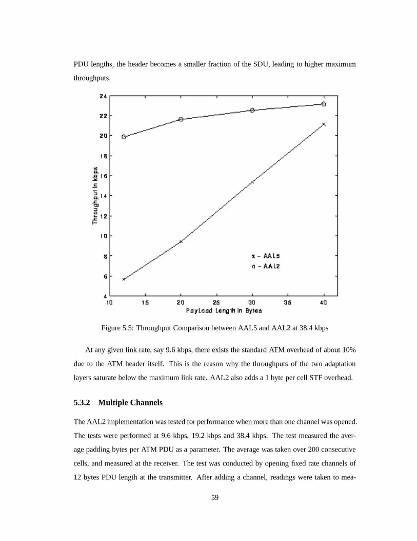
PDU lengths, the header becomes a smaller fraction of the SDU, leading to higher maximum
throughputs.
Figure 5.5: Throughput Comparison between AAL5 and AAL2 at 38.4 kbps
At any given link rate, say 9.6 kbps, there exists the standard ATM overhead of about 10%
due to the ATM header itself. This is the reason why the throughputs of the two adaptation
layers saturate below the maximum link rate. AAL2 also adds a 1 byte per cell STF overhead.
5.3.2 Multiple Channels
The AAL2 implementation was tested for performance when more than one channel was opened.
The tests were performed at 9.6 kbps, 19.2 kbps and 38.4 kbps. The test measured the aver-
age padding bytes per ATM PDU as a parameter. The average was taken over 200 consecutive
cells, and measured at the receiver. The test was conducted by opening fixed rate channels of
12 bytes PDU length at the transmitter. After adding a channel, readings were taken to mea-
59

(a) Combined Throughput and padding
(b) Avg Throughput per channel
Figure 5.6: Performance of Multiple Channels at 9.6kbps
60

(a) Combined Throughput and padding
(b) Avg Throughput per channel
Figure 5.7: Performance of Multiple Channels at 19.2kbps
61

(a) Combined Throughput and padding
(b) Avg Throughput per channel
Figure 5.8: Performance of Multiple Channels at 38.4kbps
62

sure the average padding bytes, and the average throughput over 30 second intervals on each of
the channels. Channels were added until the system saturated the bandwidth, and adding more
channels reduced the throughput of the existing open ones.
The TimerCU value was kept well below the rate of channel PDU generation so that the
effect of multiplexing can be observed well. The bit rate was fixed at 1280 bps for 9.6 kbps and
19.2 kbps tests. In order to manage the number of channels needed to saturate the link, this rate
was incremented to 2560 bps for the 38.4 kbps test.
Fig 5.6 shows the results at 9.6 kbps, fig 5.7 shows the results at 19.2 kbps and fig 5.8
shows the result at 38.4 kbps.
The fixed rate data packets were generated by pacing the transmitter. The timeout for the
pacing was calculated using
T = (106 � (L+ 3) � 8)(1
c�
1
P)
where L is the desired channel length in bytes, c is the desired bit rate of the channel and P is
the physical link rate. This gives the pacing required in�s.
Interpreting the Results
As can be seen from Fig 5.6(b), at 9.6 kbps, the first three channels opened maintain a bit rate
of 1280 bps, as expected. Upon opening the fourth channel, the link tends toward saturation,
dropping the observed rate of all the channels to 1052 bps. Adding another channel further
reduces the rate of all open channels to 963 bps.
Similarly, from Fig 5.7(b), up to six channels can be opened and maintained steady while
the seventh channel causes a drop in the combined throughputs. This is according to expecta-
tion.
In Fig 5.8(b), again six channels are opened and maintained. However, since these channels
are at twice the bandwidth of the channels at 19.2 kbps, that is all that the system can manage
before saturating.
The interesting aspect of the results is seen in the average padding bytes per ATM PDU. We
see that, regardless of the link rate, when only one channel is open, an average of 32 bytes of
63
padding is sent per ATM PDU, as the timer on the transmitter fills the SDUs with padding bytes.
However, as more channels are added, the padding is replaced by valid data on the ATM PDU,
improving the bandwidth utilization. When 3 channels are opened, the padding is at a minimum
(2 bytes), and the bandwidth is being utilized fully. The next channel forces the system to send
extra ATM PDUs, since the previous PDU would be filled by the existing channels.
� 9.6 kbps: At this link rate, the link is almost completely utilized by the existing 3 chan-
nels. Sending an extra ATM PDU at approximately the individual channel rate (since the
new PDU needs padding) saturates the link, bringing down the performance of all the
open channels (Fig 5.6(a)).
� 19.2 kbps: This link has bandwidth to spare after the first three channels have been
opened, so that the new channel opened can send ATM PDUs at it’s bandwidth without
saturating the system. Since the new ATM PDU has padding space, channels 5 and 6 can
be added by replacing this padding space, leading to an average padding rate of 2 bytes
per PDU again. Subsequently, the link saturates, and adding channel 7 brings down the
performance (Fig 5.7(a)).
� 38.4 kbps: This link is almost identical to the previous one, except that the bandwidth of
the individual channels is double that of the previous case (Fig 5.8(a)).
Channel lengths of 12 bytes are convenient to display results, since three CPS SDUs almost
exactly fill an ATM PDU. Similar results can be obtained at other channel lengths.
5.3.3 Switch Characteristics
One of the main characteristics of CBR traffic is that the PDUs are created at a uniform rate.
By extension, the receiver must also receive these with as little variation in the delay that the
data suffers in the net as possible. Thus Cell Delay Variation is a major concern for CBR traffic.
In most practical ATM systems, the switches along the path are dedicated units, that perform
the switching function exclusively. However the NATM switch runs the Linux kernel, and even
when the PC is devoted to servicing the data traffic exclusively, there are a large number of
synchronous and asynchronous events that are scheduled by the kernel, that cause the cell delay
64

(a) Inter-PDU generation times at the transmitter
(b) Inter-PDU arrival times at the receiver
Figure 5.9: Distribution of Inter-PDU times at the source and destination for a single channel
65

to vary dramatically in short bursts. However, when averaged over a large enough number of
cells, these variations tend to cancel out.
Fig 5.9(a) shows the inter-PDU generation times at the transmitter. A single channel paced
at 2000 bps over a 19.2 kbps link was opened, and the sending time of each of the PDUs was
recorded at the application level. The spikes in the figure represent the times when the process
does not get scheduled on time due to a kernel synchronous event, like the timer interrupt.
Fig 5.9(b) shows the PDU inter-arrival times at the receiver. The times are recorded when
the data actually arrives at the application. As the plot shows, the cell delay varies considerably
due to OS effects at the switch and the two end systems.
Fig 5.9 shows that, as implemented currently, the NATM switch is unsuitable for CBR
traffic. Real time modifications to the kernel scheduling algorithms will be needed to improve
performance.
5.3.4 Setup Times
Another area where AAL2 outperforms AAL5 is in setup times. Each new AAL5 connection
requires approximately the same amount of setup effort, and hence all AAL5 channels have
similar setup times. AAL2 on the other hand, requires a lot of effort to setup the first channel to
a particular host. Subsequent channels, however, are setup by negotiation among ANP daemons,
without the involvement of the intermediate switching devices. This reduces the channel setup
to about a tenth of the setup time of the first channel.
Fig 5.10 shows the comparison of setup times for AAL5 VCs and AAL2 channels, on
38.4 kbps link with one NATM switch in between. The actual numbers may indicate poor
performance, but that is due to the fact that all the switching and SAR functionality has been
implemented in software. The significant fact is the comparison of the two setup times.
66
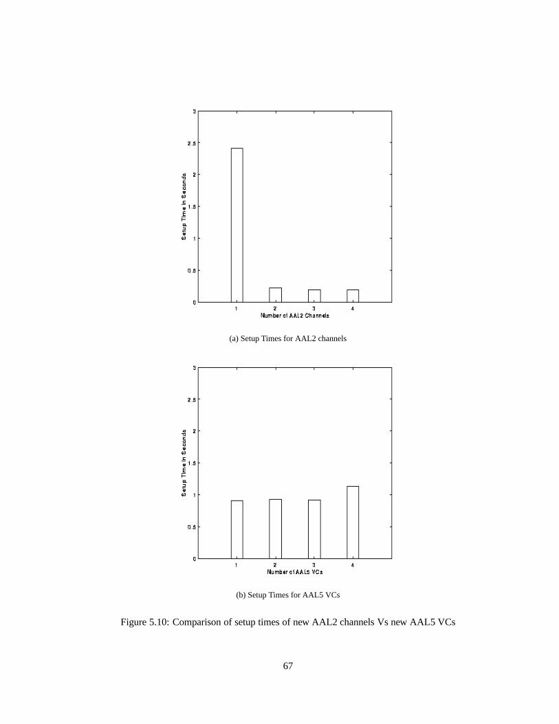
(a) Setup Times for AAL2 channels
(b) Setup Times for AAL5 VCs
Figure 5.10: Comparison of setup times of new AAL2 channels Vs new AAL5 VCs
67

Chapter 6
Conclusions
6.1 Summary
A software switch was built and used to test the AAL2 protocol. The switch was built using
Linux and Q.Port, with a Cyclades multiport card providing the required hardware support
for multiplexing many ports on a single hardware interrupt. A software switching driver, the
MicroSwitch driver, was used as a kernel level application to switch cells within the kernel. A
new fabric was written to interface Q.Port with the MicroSwitch driver.
The AAL2 protocol was implemented as an extension to an existing ATM implementation.
A simple AAL2 Negotiation Protocol was setup and implemented to assist in setting up and
tearing down individual AAL2 channels. Performance of the AAL2 protocol was studied based
on some simple metrics, and a some of it’s main advantages were explored in the context of low
bit rate CBR traffic channels. The implementation environment was calibrated, and tests were
conducted at varying link rates to provide some generality to the results.
The AAL2 Negotiation Protocol was implemented as a two part daemon, with the main
section residing in the user space and a small section in the kernel to trap and forward AAL2
socket messages. The ANP extended the BSD socket interface to support the AAL2 channel
setup and tear down, by adding AAL2 specific socket options which can be set by a user wishing
to setup an AAL2 channel.
68

6.2 Conclusions
In conclusion, we see that the ATM Adaptation Layer Type 2 is effective in improving the
bandwidth utilization of low bit rate CBR traffic channels. AAL2 successfully multiplexes
multiple channels on a single ATM VC, thereby reducing the wasted bandwidth that would be
sent in other protocols, like AAL5.
Comparisons with AAL5 demonstrated that in the case of raw throughput, the AAL2 per-
formance was far superior to AAL5 when the payloads were particularly small. This is because
AAL2 was able to utilize bandwidth otherwise wasted in padding cells to send valid data. As
the payload size approached the size of a single ATM PDU, the performance of AAL5 improved
considerably, while AAL2 remained at a steady, high value of bandwidth utilization. It was also
observed that the 3 byte header overhead of AAL2 on a per channel basis had a small effect
on the bandwidth utilization at small channel sizes. The effect of the header diminished as the
channel length increased.
We also see that by keeping the timer value low, AAL2 is able to maintain a constant bit
rate even when multiple channels are opened between the transmitter and receiver. However,
after a point of time, if too many channels are opened, the link saturates and the performance of
all the opened channels suffers.
We note that the performance of the switch in the case of CBR traffic is not satisfactory.
The OS overhead in the form of synchronous and asynchronous events which are scheduled,
tend to disturb the constant nature of CBR traffic at the receiver. However, if averaged over a
large period of time, these disturbances tend to cancel out.
6.3 Future Work
A lot of work needs to be done before the implemented AAL2 system can be practically useful:
� The ANP needs to be augmented into a full fledged protocol. Particularly, timeouts need
to be defined and implemented so that the response of the peer daemons is bounded.
� The ANP daemon needs to be stabilized and tested extensively to remove the bugs in the
implementation. The QoS negotiation in the ANP needs to be improved.
69
� The switch needs to be implemented with a real time kernel, or with real time modifica-
tions to Linux. This will improve it’s performance under CBR conditions.
� The MicroSwitch driver needs to be implemented with a high priority scheduling scheme,
along with Q.Port. The NATM Fabric needs to be extended to support a lot of the QoS
features that are not supported currently.
� The low level driver must be modified to support QoS guarantees. This will enable the
driver to maintain the throughput of negotiated channels when additional channels are
added beyond the link rate, or when any one channel exceeds it’s negotiated bandwidth.
70

Appendix A
Forward Error Correction Scheme
The Narrowband ATM network uses 24 byte PDU sizes. This is half the standard ATM PDU
size. It also uses a Forward Error Correction Scheme [11], to detect and fix as many errors as
possible at the receiver.
The FEC technique used is two fold. First, a (8, 4) Hamming code is used to reduce the
random bit errors. Second, the entire cell is interlaced, with a depth of 13, to change burst
errors into random errors. The Hamming code was employed both for it’s simplicity and ease
of implementation.
� Hamming CodeThe code word is generated as follows: each check bit of the code word
is an even parity bit corresponding to a particular subset of the data bits. Each subset
is constructed in a binary tree pattern. Any single bit error can be found and corrected
by traversing the tree, choosing a given branch based on whether the received code word
parity matches the corresponding check bit.
Data Bits 0 1 2 3 4 5 6 7
Check bit 0: x x x x
Check bit 1: x x x x
Check bit 2: x x x x
Check bit 3: x x x x x x x
� Interlacing The data to be transmitted, in the form of a cell, is arranged in columns, but
71

transmitted in rows. When burst errors, which are harder to correct than random error,
occur, then the burst is spread into random errors when the cell is reassembled at the
receiver. Each code word can now receive up to 2 errors, which can be corrected by the
Hamming code.
72
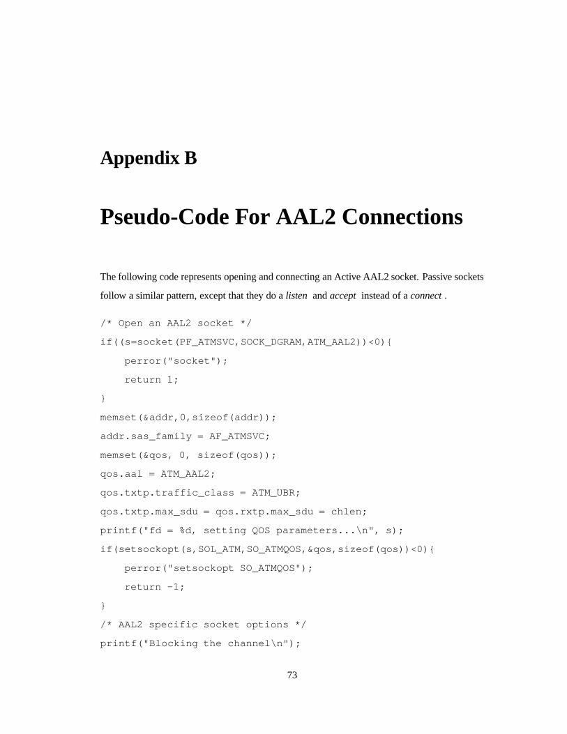
Appendix B
Pseudo-Code For AAL2 Connections
The following code represents opening and connecting an Active AAL2 socket. Passive sockets
follow a similar pattern, except that they do alisten andaccept instead of aconnect.
/* Open an AAL2 socket */
if((s=socket(PF_ATMSVC,SOCK_DGRAM,ATM_AAL2))<0){
perror("socket");
return 1;
}
memset(&addr,0,sizeof(addr));
addr.sas_family = AF_ATMSVC;
memset(&qos, 0, sizeof(qos));
qos.aal = ATM_AAL2;
qos.txtp.traffic_class = ATM_UBR;
qos.txtp.max_sdu = qos.rxtp.max_sdu = chlen;
printf("fd = %d, setting QOS parameters...\n", s);
if(setsockopt(s,SOL_ATM,SO_ATMQOS,&qos,sizeof(qos))<0){
perror("setsockopt SO_ATMQOS");
return -1;
}
/* AAL2 specific socket options */
printf("Blocking the channel\n");
73

if(setsockopt(s,SOL_ATM,SO_AAL2BLOCK,&size,sizeof(int))<0){
perror("setsockopt SO_AAL2BLOCK");
return -1;
}
printf("Setting the channel number to %d\n", chnum);
if(setsockopt(s,SOL_ATM,SO_AAL2SETCH,&chnum,sizeof(int))<0){
perror("setsockopt SO_AAL2SETCH");
return -1;
}
printf("Setting the channel length to %d\n", chlen);
if(setsockopt(s,SOL_ATM,SO_AAL2SETCHLEN,&chlen,sizeof(int))<0){
perror("setsockopt SO_AAL2SETCHLEN");
return -1;
}
printf("Setting required bandwidth to %d\n", bw);
if (setsockopt(s, SOL_ATM, SO_AAL2SETBW, &bw,sizeof(int))<0){
perror("setsockopt SO_AAL2SETBW");
return -1;
}
printf("UnBlocking the channel\n");
if(setsockopt(s,SOL_ATM,SO_AAL2UNBLOCK,&size,sizeof(int))<0){
perror("setsockopt SO_AAL2UNBLOCK");
return -1;
}
printf("trying to connect...\n");
if((connect(s,(struct sockaddr *) &addr,sizeof(addr)))<0){
perror("connect");
return -1;
}
/* Connection established */
74

Bibliography
[1] Tannenbaum A. S.,Computer Networks 2nd ed., Prentice Hall International, 1988, pp. 2-21.
[2] de Prycker M.,Asynchronous Transfer Mode - Solution for Broadband ISDN, Prentice Hall
International, 1995, pp. 105-159.
[3] The ATM Forum Technical Committee,User-Network Interface (UNI) Specification Ver-
sion 3.1, Sept 1994
[4] Almesberger, W., ”Linux ATM API, Draft Version 0.4”, Laboratorie de R�eseaux de Com-
munication, July. 19, 1996.
[5] Chen, T. M. and Stephen S. L.,ATM Switching Systems, Artech House, Incorporated, 1995,
Chapters 5-10, pp. 81-233.
[6] Black, U. D.,ATM: Foundation for Broadband Networks, Prentice Hall, Inc., 1995. Chapter
8, pp. 181-202.
[7] Onvural, R. O.,Asynchronous transfer mode networks : performance issues, Boston :
Artech House, c1994. Chapter 7, pp. 207-252.
[8] Bell Communication Research, ”LP-25”,Q.Port Portable signaling software: Implementa-
tion Notes, Release 1.3, July 1995.
[9] Bell Communication Research, ”LP-25”,Q.Port Portable signaling software: Module De-
scriptions, Release 1.3, July 1995.
[10] Almesberger, W., ”Linux ATM internal signaling protocol, Draft Version 0.2”, Laboratorie
de R�eseaux de Communication, Nov. 5, 1996.
75

[11] Lindsley, E., ”Narrowband ATM Networks”,thesis, University of Kansas, Lawrence, Au-
gust 1997
[12] Schicker, P (editor), ”B-ISDN ATM Adaptation Layer Type 2 Specification”,ITU-T Rec-
ommendation I.363.2, Feb 1997
76


